1
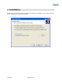
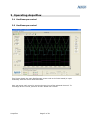
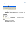
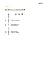
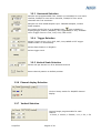
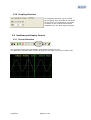
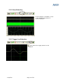
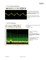
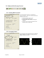
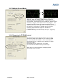
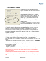
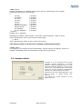
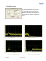
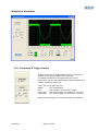
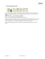
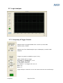
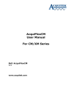
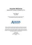
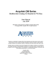
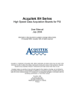
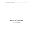
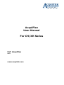
AcquiFlex
User Manual
For CH/XH Series
Ref: AcquiFlex
V2.0
www.acquitek.com
Copyright © Acquitek. All rights reserved.
Information in this publication supersedes that in all previously published material.
Specifications and price change privileges reserved.
Acquitek, 1 bis rue Marcel Paul, 91300 Massy, France
Contacting ACQUITEK
Phone: +33 1 60 13 52 73
Fax: +33 1 60 13 03 68
Address: ACQUITEK SAS.
1 bis rue Marcel Paul
91300 Massy
France
Web site: www.acquitek.com
Support
Email: [email protected]
AcquiFlex
Page 2 of 20
1 Introduction
This manual contains operating information for AcquiFlex Software Toolbox.
The manual consists of the following chapters:
1
2
3
Introduction.................................................................................................. 3
Installation ................................................................................................... 4
Operating AcquiFlex ....................................................................................... 5
3.1
Oscilloscope control ................................................................................. 5
3.2
Oscilloscope control ................................................................................. 5
3.2.1
Menu .............................................................................................. 6
3.2.2
Toolbar ........................................................................................... 7
3.2.3
Horizontal Selection ......................................................................... 8
3.2.4
Trigger Selection .............................................................................. 8
3.2.5
Vertical Scale Selection ..................................................................... 8
3.2.6
Channel display Selection .................................................................. 8
3.2.7
Vertical Selection.............................................................................. 8
3.2.8
Coupling Selection ............................................................................ 9
3.3
Oscilloscope Display Control ..................................................................... 9
3.3.1
Cursor Selection ............................................................................... 9
3.3.2
Zoom Selection .............................................................................. 10
3.3.3
Trigger Line Selection...................................................................... 10
3.3.4
Persistence Selection ...................................................................... 11
3.3.5
FFT Selection ................................................................................. 11
3.4
Advanced Oscilloscope Control ................................................................ 12
3.4.1
Auxiliary BNC Connector .................................................................. 12
3.4.2
Averaging Control........................................................................... 12
3.4.3
Multiple Record Mode ...................................................................... 13
3.4.4
Streaming to PC RAM control............................................................ 13
3.4.5
Streaming to Hard Disk ................................................................... 14
3.4.6
Waveforms saving Control ............................................................... 15
3.5
Autosave Mode ..................................................................................... 16
3.6
Digital Filtering ..................................................................................... 17
Waveform Generator ....................................................................................... 18
3.6.1
Frequency & Trigger Control............................................................. 18
3.6.2
Functions control ............................................................................ 19
3.7
Logic Analyzer ...................................................................................... 20
3.7.1
Frequency & Trigger Control............................................................. 20
AcquiFlex
Page 3 of 20
2 Installation
Please report to the CH or XH User Manual for hardware installation. Once done, just click
on the setup file and follow the process.
AcquiFlex
Page 4 of 20
3 Operating AcquiFlex
3.1 Oscilloscope control
3.2 Oscilloscope control
This figure shows the main Oscilloscope screen with a CH-3160 board (4 input
channels) with the Zoom mode activates.
User can move each curve by moving the zero line of the selected channel. To
rearrange all the curves just click on the “Reset Pos” button.
AcquiFlex
Page 5 of 20
3.2.1 Menu
1
2
1: File
3
4
Exit: Exit from AcquiFlex
Load Setup: Load parameters of Oscilloscope, Generator and logical Analyzer
previously save in .ini file
Save Setup: Save parameters of Oscilloscope, Generator and logical Analyzer. Save
parameters in .ini file
2: Instrument
Oscilloscope:
Waveform Generator:
Logic Analyzer:
3: Tools
Autosave mode: See page 14 for details
Digital Filtering mode: See page 17 for details
4: About: Show Version and Serial Number
AcquiFlex
Page 6 of 20
Show Oscilloscope display
Show Waveform Generator display
Show Logic Analyzer display
3.2.2 Toolbar
1
2
3
4
5
6
7
8
9
10 11
1:
, Print Screen
2:
, Saving selected channel
3:
, Single shot acquisition
4:
, Continuous acquisition
5:
, Stop acquisition
6:
, Horizontal Zoom IN
7:
, Horizontal Zoom OUT
8:
, Zoom Display ON
9:
, Zoom Display OFF
10:
, Cursor 1 ON/OFF
11:
, Cursor 2 ON/OFF
12:
, Persistence Mode
13:
, Trigger Line ON/OFF
14:
, Advanced scope setting
AcquiFlex
12 13
14
Page 7 of 20
3.2.3 Horizontal Selection
Sample rate programmable from 10KS/s up to 40MS/s for one active
channel, 20MS/s for two active channels, 10MS/s for four active
channels with 1Hz resolution.
Sample size from 2048 samples up to 7999488 samples, modulo
2048 samples.
icon available to
Pre-trigger mode from 0 up to Sample size.
display trigger position (ON/OFF). Pre-trigger mode is only available
when Trigger source is CH1, CH2, CH3, CH4 or EXT.
3.2.4 Trigger Selection
Select Trigger source, CH1, CH2, CH3, CH4, NONE or EXT trigger
NONE means run immediately.
Select Slope Positive or Negative
Select trigger Level
3.2.5 Vertical Scale Selection
Select Volt per division on all or Selected channel
Reset channel position to default position
3.2.6 Channel display Selection
Click on binary switch for ON/OFF channel
display
3.2.7 Vertical Selection
Vertical Range programmable for each
channel
± 50mV, ± 100mV, ± 500mV, ± 1V, ± 2V, ± 5V
AcquiFlex
Page 8 of 20
3.2.8 Coupling Selection
AC Coupling can block up to 25 VDC
DC Coupling, High impedance 1M Ohms
DC 50 Ohm, Low impedance, 50 Ohms
50 Ohms is the nominal termination
impedance for the best signal integrity.
3.3 Oscilloscope Display Control
3.3.1 Cursor Selection
Two horizontal cursors are available, attached to Channel 1 only.
The difference between both cursors is given at the right top corner in black color.
AcquiFlex
Page 9 of 20
3.3.2 Zoom Selection
A zoom display is available, cursor
1 and 2 define the portion of
curves displayed.
3.3.3 Trigger Line Selection
Icon allows the trigger position to be
displayed
AcquiFlex
Page 10 of 20
3.3.4 Persistence Selection
The Persistence setting allows
the user to control the infinite
persistence of the signal display
in the display Window
Persistence mode allows signal
monitoring and capture of erratic
events
3.3.5 FFT Selection
FFT ON bring up the multi-channels
FFT display.
Display is in dBm
A choice of Windows is
included:
Rectangular, BlackmanHarris, Hanning, Hamming,
Exact Blackman, Blackman,
Flat top
A cursor allows extracting
the frequency and
magnitude of a specific
harmonic
AcquiFlex
Page 11 of 20
3.4 Advanced Oscilloscope Control
3.4.1 Auxiliary BNC Connector
An auxiliary BNC connector is available for
several functions. Only one of these functions is
operable at any time.
•
•
•
•
External analog trigger input
D/A waveform sync output
External clock input for the analog I/O
channels
External clock output synchronous with
the A/D clock or D/A clock.
3.4.2 Averaging Control
The averaging control allows the user to capture
many records, up to 256 and average them for
display, default 10 counts
AcquiFlex
Page 12 of 20
3.4.3 Multiple Record Mode
Applicable to a triggered input capture. When set to 0
(default), XDA_Ain_Start() captures the number of
samples specified in SAMPLE field. When set to a nonzero number, it captures for this number of sample clocks
following a trigger, then waits for the next trigger. This
repeats until the number of samples specified in the
SAMPLE parameter are captured. The burst size should
be chosen as a function of sample rate so that the
minimum time between triggers is at least 10
microseconds.
It cannot be using simultaneously with pre- triggering.
3.4.4 Streaming to PC RAM control
The Streaming control allows capture of very long
stream of data, up to 64MS on one channel, 32MS
on two channels and 16MS on four channels with
Decimation factor to allows quick display of a large
amount of data.
Decimation factor range from 1 to 1000
You can save all data in binary format only
Note that you cannot perform averaging while
streaming mode is active.
AcquiFlex
Page 13 of 20
3.4.5 Streaming to Hard Disk
The Streaming to Hard Disk feature allows to
capture continuously data from the A/D converter
to your local hard disk.
The maximum rate that the board can sustain on
the PCI bus is 80MB/s (one channel at 40MS/s, 2
channels at 20MS/s or 4 channels at 10MS/s).
Therefore when saving directly on hard disk, the
maximum observed transfer rate is reduced to
40MB/s. This is really the best case using last
performing component. There is many source of
problem that could decrease this writing speed as
the chipset disk controller, the hard disk itself…
Also remember that Windows is not a real time
operating system.
To avoid any problem during a streaming capture,
avoid running other application, browse your disk,
move the mouse, etc…
If your system is not able to sustain the data throughput, you will receive a “Buffer
Overwrite” error and it will stop the acquisition.
To allow the maximum high speed rate up to 40MS/s (80MB/s), user can enable the
saving on ‘PC RAM First’ by selecting the switch (“To PC RAM first / To Hard Disk”).
A limit is fixing to the max available physical RAM space minus few Megasamples for
proper use. In this mode, it allows streaming up to 40MS/s on one channel or 20MS/s on
two channels. All data are collected to PC RAM then directly save on the Hard disk at the
end of the acquisition.
- To Enable Streaming to Hard Disk feature, select the square box.
- Max File Size (MS): this control allows fixing the length of the record This parameter is
expressed in MegaSample (MS) modulo 20MS. It represents the total amount of samples
for all the channels. The total file size on your local disk will be twice this value. If value
= 100MS, the file size will be 200MB (or 200*1024*1024 = 209715200 Bytes).
Note that you can stop at any time the streaming capture by pushing the Stop icon of the
toolbar.
- Stream File: You can select the storage directory. The name of the File is “Stream.dat”
According to the sampling rate, you can easily calculate the acquisition time.
Acquisition_time = Max_File_Size / Sampling_Rate / NumChan
If Max_File_Size = 7200MS
Sampling_rate = 1MS/s
Number of Channel = 2
ÎAcquisition_Time = (7200*1024*1024) / 1e6 / 2 = 3775 sec ( about 1hour)
IMPORTANT NOTE: Although AcquiFlex is running only on Windows 2000 or Windows XP, which
both support NTFS File system, some users still work with FAT32 drives to ensure compatibility to
older Windows versions.
FAT32 formatted drives are limited to a .le size of 2 GBytes !!! So if you still use a FAT32 formatted
drive to store your acquisition data, make sure that you do not exceed the 2 GBytes limit either by
doing only short time measurements or by setting up the multiple option accordingly.
We at Acquitek strongly recommend the use of a NTFS formatted hard disk to store your acquisition
data.
AcquiFlex
Page 14 of 20
3.4.6 Waveforms saving Control
Click on Diskette to enable
channel saving mode
Select Channel to be saved and
click on save button
The three formats available are
asc, dat and awg
*.asc: ASCII
The ASCII file content header with acquisition parameters:
Acquisition on CH1
Date: 11/1/2005 at 16:49:16
Sampling rate: 10000000
Input Range: 2.00
Total Number of Samples: 4096
Number of Pre-Samples: 0
-0.806641
-0.776367
-0.445312
0.051758
0.532227
0.809570
0.774414
0.443359
AcquiFlex
Page 15 of 20
*.dat: Binary
Header information is available at the top of the file, following by the raw data
Information Structure of the Header
{
int Day;
// 4 bytes
int Month;
// 4 bytes
int Year ;
// 4 bytes
int Hour ;
// 4 bytes
int Min ;
// 4 bytes
int Sec ;
// 4 bytes
double iClockRate ; // 8 bytes
double Range ;
// 8 bytes
int Samples ;
// 4 bytes
int pre_Samples ;
// 4 bytes
} Header ;
Header size = 48 bytes
Raw data are signed 16-bit integer. It can take values between –2047 to 2047
-2047 Î Minimum value of the current input range
0 Î 0V
2047 Î Maximum value of the current input range
This binary format is the only one available in Streaming capture.
*.awg: ASCII
Two columns, one column as time information, second column as voltage. This file is
straight compatible with the CubeScope-20 waveform generators.
3.5 Autosave Mode
Autosave is a very powerful tool for data
transient signals acquisition. It allows
signals monitoring and data capture to disk
with time and date stamping on the trigger
occurrences. The channels are saved to file
using the current hardware configuration
defined in the Oscilloscope instrument.
Waveforms are saved automatically on the
disk in binary or ASCII format, user
selection.
The dialog box allows selection of the
target directory
AcquiFlex
Page 16 of 20
3.6 Digital Filtering
User can apply a digital filtering on the acquired
waveform and get the result in real-time on his
screen.
User select a Filter type (Low-Pass, High-Pass,
Band-Pass and Band-Stop), the Lower Cutoff and
Higher Cutoff Frequency and the number of Tap (1
to 1024).
To activate this mode, select the “Enable Filtering
control”
No Filtering
Low-Pass Filter 1MHz
Band-Pass Filter (400kHz-600kHz)
AcquiFlex
Band-Stop Filter (400kHz-600kHz)
Page 17 of 20
Waveform Generator
3.6.1 Frequency & Trigger Control
Output frequency is programmable from 0.01Hz up to
10MHz (one channel) 5MHz (two channels)
The 8MHz bandwidth of the generator will cause
attenuation for any generated signal between 8MHz and
10MHz. Default is 10000 Hz.
There are four trigger sources
NONE:
Run immediately
EXT:
Run infinitely on external Trigger
CH1 Input: Run when trigger on Channel 1 occurred
CH2 Input: Run when trigger on Channel 2 occurred
Slope and Level apply on Input Channels and Auxiliary
AcquiFlex
Page 18 of 20
3.6.2 Functions control
Type: Sine, Square, Triangle, Sawtooth, White Noise, DC and arbitrary Waveform File
Amplitude: Output amplitude is +/- selected value into 50 Ohms, +/-5V maximum, 1V
default
Offset: DC value, +/- 5V maximum, 0V default
Phase: -360° to +360°, 0° is the default value
Noise: Add 10% of selected amplitude with white noise
When File wavetype is chosen, selects the file containing waveform data. Each line of the
file should contain a time offset value followed by a tab, then the sample value in volt
and a carriage return. The number of samples must be a multiple of 32.
Press the ON button of the selected channel to generate the waveform. Press OFF to
stop.
AcquiFlex
Page 19 of 20
3.7 Logic Analyzer
3.7.1 Frequency & Trigger Control
Sample Rate is programmable from 10 KHz up to 40 MHz
Default value, 10MHz
Sample size from 2048 samples up to 1MSamples, modulo 2048
samples.
Trigger on pattern available on port 0 only
Mask: Enable bit for trigger
Ex: Mask = 7 enable bit 0, 1 & 2
Mode: NONE, PATTERN
If PATTERN is selected
Ex: Pattern = 4, trigger will occur on
Bit 0 = 0
Bit 1 = 0
Bit 2 = 1
Logic Analyzer cannot be use in the same time with the oscilloscope
AcquiFlex
Page 20 of 20