1
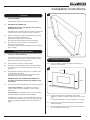
Riva2 670 Electric
Instructions for Use, Installation & Servicing
For use in GB & IE (Great Britain & Republic of Ireland).
IMPORTANT
THE OUTER CASING, FRONT AND GLASS PANEL BECOME EXTREMELY HOT DURING OPERATION AND WILL
RESULT IN SERIOUS INJURY AND BURNS IF TOUCHED. IT IS THEREFORE RECOMMENDED THAT A FIREGUARD
COMPLYING WITH BS 8423:2002 IS USED IN THE PRESENCE OF YOUNG CHILDREN, THE ELDERLY OR INFIRM.
For use with 230v 50Hz electricity supply only.
Please read these instructions carefully before installation and keep them in a safe place.
They will be needed when maintenance or servicing is required.
THIS APPLIANCE MUST BE EARTHED
PR1684 Issue 5 (September 2015)
Contents
Covering the following models:
Electric Riva2 670
234-872
User Instructions........................................................3.
1.
2.
3.
4.
Important Information & Health and Safety............................. 3
Operating Instructions............................................................. 3
Fitting Fronts........................................................................... 5
Maintenance............................................................................ 5
Installation Instructions.............................................6.
Technical Specifications.............................................................. 6
Appliance Dimensions................................................................. 6
Front Dimensions........................................................................ 6
Installation...................................................................7
1. General.................................................................................... 7
2. Fitting the Appliance................................................................ 7
3. Care & Maintenance............................................................... 9
Servicing...................................................................10
1. Fault Finding......................................................................... 10
2. How to Wire a Plug............................................................... 10
3. Servicing Requirements........................................................ 11
4. Removing the Screen............................................................ 11
5. Removing the Fuel Bed........................................................ 11
6. Removing the Front Panel.................................................... 12
7. Replacing the Effect Engine.................................................. 12
8. Replacing the LED Boards.................................................... 12
9. Replacing the Heat Assembly............................................... 12
10. Replacing the Remote Sensor............................................ 13
11. Replacing the PCB Unit....................................................... 13
12. Replacing the Thermostat Control Board............................ 14
Spare Parts List........................................................14
Wiring Diagram.........................................................14
2
To receive your Extended Warranty your Gazco appliance must have
been purchased from our Expert Retailer Network and registered within
one month of purchase or installation. Please note that all warranties
are effective from the date of purchase. Any Gazco product purchased
outside of our Extended Retailer Network, or not registered within the
stated time will carry a standard 12 month warranty.
Full terms and conditions are detailed in the Warranty Statement on
the Gazco website www.gazco.com. In the event of any conflict of
information the wording on the website shall prevail.
Important Note: Should any problems be experienced with your
product, claims must first be submitted to the Expert Retailer where
the appliance was purchased from who will offer immediate assistance
or contact Gazco on your behalf.
Registration No WEE/DH1656ZW
In accordance with European Directive 2002/96/
EC, waste electrical and electronic equipment
(WEEE) must not be disposed of with household
waste.
At the end of its useful life please take this product to an appropriate recycling centre or collection point. You can find your nearest recycling
centre by using the bank locator at
www.recycle-more.co.uk for UK customers,
www.weeeireland.ie for customers in the
Republic of Ireland, or by contacting your local
authority.
User Instructions
1. Important Information and
Health and Safety
1.1
Read all of the instructions carefully before using the
appliance.
1.2
Remove all packaging and dispose of at an appropriate
recycling facility.
1.3 Do not locate this appliance immediately below a fixed
socket outlet.
1.4
The outer casing of this appliance is considered by the
manufacturer to be a working surface which becomes hot
when the fire is switched on. You must use a suitable fire
guard to protect children, the elderly and the infirm.
1.5 Do not use this appliance in the immediate surroundings of
a bath, shower, swimming pool or any other area where the
appliance could come into contact with water or humidity,
e.g. a bathroom.
1.6
WARNING! DO NOT COVER
Do not allow the appliance to be covered or let the air inlet/
outlet become obstructed as the appliance may overheat.
Please note the warning symbol on the appliance (see
above).
1.7
For indoor use only. This appliance is not suitable for use
outside the house.
1.8
Keep the power cord away from hot surfaces and hot
conditions. Do not route the power lead in front of the
appliance.
1.9
This appliance must be firmly fixed into a recessed opening
or to a flat internal wall using the optional Wall Mounting
Bracket. Ensure that furniture, curtains etc. are positioned
no closer than 1m to the appliance.
1.10 If the installation is to be at floor level the appliance must
stand on a non combustible surface which projects at least
300mm in front of the appliance.
Do not allow rugs or carpets to be placed within 300mm of
the front of the appliance.
1.15 Do not operate the appliance if it is damaged.
1.16 Repairs of electrical appliances must only be performed by
an electrical engineer. Should the appliance fail to operate,
or in case of any damage, please contact the retailer from
whom the appliance was purchased.
1.17 Never leave the heater unattended while it is in use.
Always switch the product to the OFF position and unplug it
from the electrical outlet when not in use.
1.18 This appliance is not intended to be used by persons
under the age of 12, persons with reduced physical,
sensory or mental capabilities or persons with lack of
experience and knowledge in the safe operation of the
appliance.
The appliance may be operated by persons above the
age of 12 provided they have been instructed in the safe
use of the appliance and that they understand the hazards
involved. Persons above the age of 12 may also operate the
appliance under the supervision of a responsible adult.
1.19 Parts of this appliance become hot whilst in operation and
under no circumstances should persons under the age of 12
be left alone with the product when it is in operation unless
a suitable fireguard is used to protect them against the
possibility of coming into direct contact with the appliance.
2. Operating Instructions
WARNING! DO NOT OPERATE THE APPLIANCE IF
IT IS DAMAGED OR HAS MALFUNCTIONED. IF YOU
SUSPECT THE APPLIANCE IS DAMAGED OR HAS
MALFUNCTIONED CALL A QUALIFIED SERVICE
ENGINEER TO INSPECT THE APPLIANCE, AND
REPLACE ANY PART OF THE ELECTRICAL
SYSTEM IF NECESSARY, BEFORE REUSE.
GENERAL
2.1
The appliance can be operated by the infrared handset or
the manual controls which are on the right hand side of the
lower front panel.
PREPARATION BEFORE USE
Batteries:
1.11 When the fire has been installed, the position of the plug
must be accessible.
2.2
Ensure that the handset battery is new and is inserted correctly.
1.12 Where the electricity supply cable has to pass through afire
place, stone surround etc. ensure suitable rubber bushes
are fitted at possible wear points.
2.3
Dispose of old batteries at an appropriate recycling facility.
When using the handset:
1.13 If the electricity supply cable is damaged do not use the
appliance until it has been replaced. For safety reasons the
replacement has to be carried out by Gazco, a Gazco
service agent or a similarly competent electrician.
2.4
Ensure the handset is pointed at the infrared sensor located behind the flame effect screen at the back of the inside of the appliance.
1.14 Do not use this appliance with any kind of timer,
programmer or thermal control or other device that will
switch the appliance on or off automatically.
LOCATION OF POWER SWITCH
2.5
The mains power switch is located on the control panel
located on the right-hand side of the appliance behind the
door of the frame, see Diagram 1 over page.
3
User Instructions
2.6
Switch ON (—) before operating either the remote or manual controls.
2.7
The fire will beep once to indicate that the fire is ready to use.
2.8
For periods of non use set the isolation switch to OFF (O).
Remote & Manual Operation
Standby ON/OFF
2.12 The appliance is in Standby mode when the power is
switched on via the manual control panel. You must have
this power supply ON (—) before using the manual or
remote controls.
Turning On the Appliance
2.9
The following functions can be controlled using the manual
controls or remote handset:
Flame Effects:
—Heat settings 1 and 2
—Brightness of the fuel and flame effect
2.13 The flame effect button on both the manual and remote
controls has 4 settings:
2.10 The Standby function and the thermostat can only be
operated via the manual controls.
2.11 The effects can be turned off using the remote, returning the
appliance to Standby, see Diagram 2.
1
—Press once for maximum brightness level with extra
blue flames.
—Press twice for maximum brightness without blue flames.
—Press three times for medium brightness level.
—Press four times for minimum brightness level.
Turning On The Heat:
2.14 When turning on the heater you must always press the
1kW button. Do not start the fire using the 2kW setting.
2.15 It is NOT possible to run the heater without the flame
effects switched on.
2.16 Press the 1kW button to turn the fan heater ON. One red indicator light will be displayed on the indicator (1)
- See Diagram 3. The appliance will blow cold air for
approximately 8 seconds before the heater comes on.
On this setting the heater will operate at half its maximum
temperature.
Standby
On/Off Switch
Flame setting
button
Heat setting
button
Temperature
thermostat
On/Off button
2
Flame effect
2.17 Press the 2kW button once to turn the fan heater to its maximum temperature. Two red indicator lights will be displayed on the indicator (1) + (2) in the top right hand
corner - See Diagram 3. After approximately 8 seconds the
heater will operate at its maximum temperature.
3
1
2
Heat setting 1kW
Heat setting 2kW
2.18 Pressing the 2kW button again will turn the heater OFF
and cold air will continue for 8 seconds.
2.19 Press the 1kW button to return to the lower heat setting.
2.20 Press the On/Off button to turn off ALL settings and return to Standby.
2.21 The appliance should be turned off via the On/Off
switch when it is not in use.
4
User Instructions
4. Maintenance
Thermostatic Control
ALWAYS UNPLUG FROM MAINS SUPPLY BEFORE
CLEANING OR UNDERTAKING ANY MAINTENANCE
2.22 The appliance is fitted with a thermostat. This is located on
the right hand panel of the appliance, Diagram 1.
4.1
GENERAL CLEANING
The thermostat can control the room temperature between
approximately 9˚C and 34˚C. The edge of the thermostat
control dial is numbered 1 - 9 with 1 being the coolest
setting and 9 being the warmest. If the room temperature
is too high turn the thermostat dial in an anti-clockwise
direction. If the room temperature is too low turn the dial in a
clockwise direction.
Log Effect
4.2
Only clean the outer casing when it is cold. Do not use
abrasive cleaners.
CLEANING AIR INLETS
4.3
Ensure the appliance is unplugged.
4.4
Clean the air inlet (a) and outlet (b) grilles regularly with a
soft cloth or the nozzle of a vacuum cleaner, see Diagram 4.
2.23 The Log effect is a glass fibre fuel bed which may give
off a slight smell when first used. This is normal and
should disappear after a day or two.
4
Thermal Safety Cutout
The appliance is fitted with a thermal safety cutout,
which operates if it overheats. If this happens:
a
2.24 Unplug the appliance and allow it to cool for 5 - 10 minutes.
b
a
2.25 Check the air inlets/outlets for any obstruction and clear if necessary (see Maintenance, Section 4.5).
Dust build-up can inhibit efficient performance of the
fan and lead to the safety cut-out operating.
2.26 Plug in appliance and switch it on. The cutout will re-set and
the appliance should function correctly. If this is not the case:
4.5
Keep the area around the appliance clean and free of fluff,
dust or pet hair.
2.27 Unplug once more and have the fire checked by a competent electrician.
4.6
In particular, build-up of dust etc. can occur around and under
the heater area. Take particular care to keep this area free
from such particles on a regular basis to prevent build-up.
3. Fitting Fronts
BATTERY REPLACEMENT
3.1
The electric Riva2 670 is designed to accept several
different decorative fronts. For individual fixing methods
refer to the front installation instructions.
4.7
When the remote batteries are low they must be changed
immediately. Install correct replacement and dispose of the
old batteries carefully.
3.2
When installing the Riva2 670 with a Wall Mounting Kit
the addition of side mounting brackets are required before
fitting the Evoke, Verve or Verve XS fronts. See Installation
Section 2.31.
Note: If the appliance is to be left for a long period
of time ensure it is switched off and the power cord
removed.
5
Installation Instructions
Technical Specification
These instructions cover the following models:
Electric Riva2 670
234-872
These appliances have 3 modes of operation:
—Flame effect only - with 4 brightness levels
—Flame effect + 1kW heating
—Flame effect + 2kW heating
A 230v 13amp 50Hz supply is required
Maximum power consumption:
2064 Watts
THIS APPLIANCE MUST BE EARTHED
A 1.8 metre lead with plug containing a 13 amp fuse is supplied. Only use a 13 amp fuse with this appliance.
Remote control handset battery (CR2032)
This appliance has been certified for use in countries other than
those stated. To install this appliance in these countries, it is
essential to obtain the translated instructions and in some cases
the appliance will require modification. Contact Gazco for further
information.
PACKING CHECKLIST
Appliance Description
Fixing Kit containing:
Riva2 670 Electric
1
4
4
1
2
1
This appliance is compatible with the following fronts:
Verve
Verve XS
Designio2 Glass
Designio2 Steel
Evoke Glass
Evoke Steel
Appliance Dimensions
x
x
x
x
x
x
Instruction Manual
Screws
Rawl plugs
Handset
Retention screws
Battery
Front Dimensions
655 mm
A
568 mm
B
525 mm
680 mm
105 mm
6
C
Front
A
B
C
Verve
621
1325
167
Verve XS
621
1000
166
Designio2 Glass
569
735
150
Designio2 Steel
569
735
150
Evoke Glass
622
920
150
Evoke Steel
622
920
150
Installation Instructions
1. General
1.1
TOOLS REQUIRED
A Screw Driver, Spirit Level and Drill will be needed.
1.2
UNPACKING THE FIREPLACE
WARNING! DO NOT use this appliance if any part has
been exposed to water.
Immediately call a qualified service technician to inspect and
to replace any part of the electrical system if necessary.
1.3
Open the packaging carefully and remove the polystyrene.
Remove and discard the plastic bag.
Keep plastic wrapping away from children.
Be responsible when handling the packing materials.
1.4
Check all parts and accessories are removed before
disposing of any packaging.
If necessary keep the original packaging for future transport
and/or storage.
2.1
2.2
For best results, install out of direct sunlight.
2.3
If the power cord is damaged contact your Gazco retailer
for a replacement. Only use genuine Gazco parts on this
appliance.
105 mm
2a. Recessed Installation
2.6
Prior to installation ensure the minimum clearances are
observed, see Diagram 2.
2
300mm
The appliance should be located close to a suitable mains
socket to enable connection.
The electrical socket must be easily accessible to allow
disconnection when the appliance is fitted.
WARNING! KEEP ANY COMBUSTIBLE MATERIALS
AT LEAST 1M FROM THE FRONT AND SIDES OF THE
APPLIANCE.
2.5
This Riva2 670 can be installed using the following methods:
1. Recessed Installation - the appliance is located in
a purpose built recess. See Diagram 1 for the opening
dimensions.
2. Wall Mounted - the appliance is hung on the wall using
the optional Wall Mounting Kit (Part No. 8688SL).
665 mm
Locating the Riva2 670 Electric
The Riva2 670 Electric may be installed virtually anywhere
in your home. However, when choosing a location ensure
that the general instructions are followed.
535 mm
2. Fitting the Appliance
2.4
1
If installing onto a hearth or non-combustible floor ensure a
front which allows hearth mounting is used (Designio2). All
other fronts require the appliance to be raised above floor
height.
150mm
2.7
2.8
2.9
150mm
Decide on the height of the appliance ensuring the
appliance is raised to a distance appropriate for the chosen
front.
For measurements refer to the front dimensions on page 6.
Prepare the recess opening according to the dimensions
stated in Diagram 1.
Offer the appliance into the recess and mark the position of
the four fixing holes on the wall.
7
Installation Instructions
2.10 Drill the 4 holes and insert the rawlplugs provided.
Note: The rawlplugs supplied are suitable for solid wall
applications. If it is intended to mount the appliance onto
plasterboard or hollow walls suitable fixings must be used.
2.11 Secure the appliance to the wall with the screws provided.
2.12 Fit the chosen front according to the instructions supplied.
2.21 Place the fixing plugs into the holes and secure the upper
bracket using the screws provided.
Fire Box
2.22 Lower the ‘fire box’ onto the top wall bar hook so that the
rear slot on the top of the fire locks over the hook.
2.23 Rotate the ‘fire box’ flat to the wall so that the flange in the
lower bar fits with the bottom fire box slot, see Diagram 4.
2b. Wall Mounted Installation
2.13 Prior to installation ensure the minimum clearances are
observed, see Diagram 2.
4
IMPORTANT Before fitting consider whether
different wall fixing plugs need to be purchased to
support the weight of the chosen frame on the
intended type of wall.
Additional fixing holes may be required in the wall
bars to strengthen the structure for heavier frames
or studwork walls.
Wall Bars
2.14 The Top bar has a hook.
Lower bar has flange and screw hole, see Diagram 3.
2.15 Make sure there are no pipes or cables behind the area you
drill.
2.16 Decide on the height of the appliance ensuring the
appliance is raised to a distance appropriate for the chosen
front.
For measurements refer to the front dimensions on page 6.
2.24 Use two No.6 x 12 screws from the kit to fix the fire through
both sides into the holes in the lower bar.
IMPORTANT: IT IS VITAL THAT THE APPLIANCE
POWER SUPPLY IS CONNECTED TO THE PRODUCT
AT THIS STAGE.
2.17 Position the Lower Fixing Bracket and mark the positions
for the retaining screws. Remove the bracket and drill the
holes.
2.18 Place the fixing plugs into the holes and secure the lower
bracket using the screws provided.
Wall Box
2.25 Join the three pieces of wall box together, See Diagram 5.
5
2.19 Place the Upper Hook Bracket on the wall and mark the
position ensuring that the distance between the bottom of
each bracket is 425mm, see Diagram 3.
3
Upper Hook Bracket
150mm plus the
distance between the
edge of the frame and
the appliance body
Step 2
Step 1
M4 Nuts
Number of fixings will
depend on wall
constructions. Additional
fixings may be added if
necessary
Lock Washers
425mm
Washers
Lower Fixing Bracket
Desired height
from floor
2.26 Insert threaded studs in the sides through the holes in the
end flanges of the top.
2.20 Use a spirit level to check the bars are straight. Mark the
positions for the retaining screws. Remove the bracket and
drill the holes.
8
2.27 Assemble the wall box using the washers, nut lock washers
and M4 nuts supplied.
Before tightening, make sure the front face of the box
structure is level.
Installation Instructions
2.28 Press face down onto a soft flat surface to protect from
scratching or damage.
2.29 Now tighten the nuts.
2.31b All Other Frame Types
2.30 With the appliance power supply in place:
Fix the wall box to the appliance frame using the 9 screws
supplied, see Diagram 8.
8
- Slightly widen the legs of the wall box and lower it over the
‘fire box’ so its hooks clear the top wall bar, see Diagram 6.
6
2.32 Complete the installation of the Electric Riva and the
decorative frame by following the relevant instructions
provided.
- Let the legs spring back once over the top bar to engaged
with the lower bar.
2.31a Installing With Verve, Verve XS and Evoke Frames:
Fix the wall box to the appliance frame and the side
brackets supplied with the frame using the 9 screws
supplied, see Diagram 7.
Note: Lip of the appliance should sit in front of the wall
box and the Side Bracket plates are fitted in front of the
appliance. The Mounting Brackets for the frames can then
be attached to the Side Bracket Plates.
The appliance power cable can be hidden from view by
either sinking it into the plaster of the wall behind a suitable
conduit, or by running it through a surface mounted channel.
THE POWER CABLE SHOULD NEVER BE HARD
WIRED INTO THE ELECTRICAL WIRING OF THE
HOUSE AND THE PLUG AND FLEX SHOULD
NOT BE ALTERED IN ANY WAY. SUCH ACTION
WILL INVALIDATE THE WARRANTY AND
COULD EFFECT THE SAFE OPERATION OF THE
APPLIANCE.
3. Care & Maintenance
7
Do not use abrasive cleaners on the wall box as this
may damage the finish.
3.1
Use a lint-free damp cloth to wipe clean.
3.2
For the frame and appliance follow the instructions included
with them.
Side
bracket
plates
9
Servicing
Live Wire
1. Fault Finding
NO ILLUMINATION OR UNEVEN LIGHTING:
1.1
1.2
Check the heater is working. If YES, one or more of the LED
boards will need replacing. This must be undertaken by a
suitably qualified person (see Servicing Requirements).
If NO, first change the 13amp fuse for one known to work.
If the fire still does not work, check the socket by plugging
in a working appliance. If this too fails to operate, call in a
competent electrician to check the socket.
Brown
Terminal L / RED
Neutral Wire
Blue
Terminal N / BLACK
Earth Wire
Green & Yellow
Stripes
THIS APPLIANCE MUST BE EARTHED
European Plug
Suitable for use in Austria, Belgium, Bulgaria, Czech
Republic, Denmark, Estonia, Finland, France, Greece,
Hungary, Germany, Italy, Latvia, Lithuania, Luxembourg,
Netherlands, Poland, Portugal, Romania, Slovakia,
Slovenia, Spain & Sweden
ILLUMINATION BUT NO HEAT:
1.3
1.4
The safety cut-out has operated to protect against
overheating (see User Instructions, Section 2). Ensure
the air inlet and outlet grilles are free of dust or any other
obstruction.
Terminal E /
/ GREEN or
GREEN & YELLOW
2
Typical European Plug
Type 15/16/17
The thermostat control dial may be set too low. Turn the dial
clockwise until the heater turns on.
Neutral wire
REMOTE CONTROL FAILS TO WORK:
1.5
Check that the batteries are new and correctly fitted. Replace if necessary.
1.6
Ensure that the handset is pointed towards the fire.
Earth wire
2. How to wire a plug
To change the plug supplied with this fire, follow the
instructions below. The instructions assume that the wire
has been cut.
WARNING – FAILURE TO CONNECT THE WIRES
CORRECTLY COULD PUT PEOPLE AT RISK FROM
ELECTRIC SHOCK OR FIRE. IF IN DOUBT
CONSULT A QUALIFIED ELECTRICIAN.
UK Plug
Suitable for use in Cyprus, Malta, Ireland & Great Britain
1
UK Plug Supplied
Type 33
Earth wire
Fuse
Neutral wire
Live wire
Outer Insulation
10
Cable grip
Live wire
Outer Insulation
Cable grip
2.1
Dispose of the old plug safely. Ensure the new plug is not
cracked or chipped.
2.2
Expose 4cm of the coloured wires and trim to the correct
lengths so that they comfortably reach the correct terminals.
2.3
Ensure that the Earth wire has more slack than any of the
other wires.
2.4
Remove some of the insulation to leave about 1cm of
exposed metal core on each wire. 2.5
Twist the strands of the wire together.
2.6
Loosen the screw heads above each terminal.
2.7
Push the metal wire into the hole beneath each screw head
or, dependent on plug design, wind the metal wire around
the screw.
2.8
Ensure that the insulation reaches right up to each terminal
as illustrated and there are no loose strands of wire.
2.9
Ensure the cable sits correctly under the cable grip and
tighten to secure.
2.10 Refer to Technical Specification for fuse rating and fit the
appropriate fuse into the plug.
2.11 Attach the plug cover.
Servicing
3. Servicing Requirements
4. Removing the Screen
THIS APPLIANCE MUST ONLY BE SERVICED BY A
SUITABLY QUALIFIED PERSON.
4.1
Remove the 2 screws and lift the bracket away from the
screen, see Diagram 3.
BEFORE UNDERTAKING ANY WORK ON THE APPLIANCE:
SWITCH OFF THE APPLIANCE AND ISOLATE IT FROM
THE MAINS BY UNPLUGGING THE UNIT.
Note: When replacing the bracket there is a flange that
hooks over the top of the glass to hold the screen in place.
3.1
Wait for at least 10 minutes until the appliance has cooled down.
4.2 Pull the glass forward and lift out of the channel.
Remote Handset Battery Replacement
3.2
3
Screws
Replace with a CR2032 battery. Make sure the battery is
installed correctly in the remote control.
Maintenance of Motors
3.3
Fuel bed
The motors used on the fan and flame effect are prelubricated for extended bearing life and require no further
lubrication. However, periodic cleaning/vacuuming of the
fan/heater unit is recommended.
Resetting the Thermal Cutout Switch
3.4
The appliance is fitted with an Electronic Safety Control
(E.S.). This is a safety device which switches off the fire if,
the appliance overheats for any reason e.g. when covered.
If the heater stops operating whilst the flame effect
continues normally, this indicates that the E.S. Control is in
operation.
The E.S. Control can only be re-set after the appliance has
cooled down.
To re-set the E.S:
Switch off the appliance (Manual On/Off switch) and leave
for approximately 10-15 minutes.
Remove any obstruction to the fan heater outlet or other
internal parts.
Switch on appliance and the E.S. Control will re-set. Ensure
that the appliance is functioning correctly. If the E.S. Control
operates again, the appliance should be checked by a
competent Electrician.
5. Removing the Fuel Bed
5.1 Remove the screen, see section 4.
5.2
Remove the 2 screws on either side of the appliance, see
Diagram 4.
4
Screws
5.3
Remove the 4 screws on the back (2 on either side of the
back), see Diagram 5.
5
Screws
11
Servicing
5.4
Remove the 2 side covers by carefully sliding forward.
5.5
Lift the fuel bed carefully out through the front of the
appliance.
6. Removing the Front Panel
6.1
Lay the appliance on its back on a flat surface.
6.2 Remove the bottom front panel by removing the 3 screws
from the right side, 3 from the left side and 3 from the
bottom of the appliance.
6
8. Replacing the LED Boards
8.1
8.2 It is advisable to remove the bottom front panel to access
the effect engine, see section 6.
Front LED board
8.3
Unplug the wire connected to the LED board.
8.4
Using a pair of long nosed pliers remove the board from the
plastic pegs securing it to the appliance.
8.5
Rear LED Board
Effect Engine
Front LED Board
PCB
8.6
Remove the plastic cover by removing the 4 screws
8.7
Remove the 2 screws on either side of the LED board.
8.8
Using a pair of long nosed pliers remove the board from the
plastic pegs securing it to the appliance.
8.9
Thermostat Control Board
7. Replacing the Effect Engine
Refer to sections 4 and 5 to remove the screen and fuel bed.
7.2 It is advisable to remove the bottom front panel to access
the effect engine, see section 6.
7.3
Replace in reverse order.
Rear LED board
Remove the 4 screws on the back of the appliance, see
Diagram 7.
Replace in reverse order.
Dispose of any old boards at an appropriate recycling centre.
6.3 It is now possible to access all components.
7.1
Refer to section 4 to remove the screen.
9. Replacing the Heater Assembly
9.1
Refer to sections 4 to remove the screen.
9.2 It is advisable to remove the bottom front panel to access
the effect engine, see section 6.
Remove the Heater Cover
9.3
Remove the 4 screws, 2 on either side of the appliance
9.4
Remove 3 screws closest to the front on top of the
appliance, see Diagram 8.
7
8
Screws
7.4
Unplug the LED boards and wires.
7.5Replace in reverse order ensuring the wires are put back in
exactly the same configuration.
12
Screws
Servicing
Remove the Heater Assembly
9.5 Remove the 3 screws towards the rear of the top of the
appliance, see Diagram 9.
9
10. Replacing the Remote Sensor
10.1 Refer to sections 4 to remove the screen
10.2 It is advisable at this stage to remove the bottom front
panel, see section 6.
Screws
10.3 Disconnect the sensor lead from the PCB and remote
sensor and carefully move to one side.
10.4 Remove the 2 screws and using a pair of long nosed pliers
squeeze the clips that hold the sensor bracket to the heater
assembly in order to release, see Diagram 12.
12
9.6
9.7
Top right of appliance
Remove the 3 screws at the top of the back of the
appliance.
SUPPORT THE HEATER ASSEMBLY WHILST REMOVING
THE SCREWS.
Undo 4 screws to remove the fan heater assembly, see
Diagram 10.
10
10.5 Remove the sensor and replace as required.
11. Replacing the PCB Unit
11.1 Refer to sections 4 and 5 to remove the screen and fuel bed.
11.2 Lay the appliance on its back on a flat surface.
11.3 Remove the bottom front panel, see section 6.
11.4 Remove the 2 screws and using a pair of long nosed pliers
squeeze the clips that hold the PCB to the appliance in
order to release.
11
13
Bottom right of appliance
PCB
9.8 Replace in reverse order ensuring the wires are put back in
exactly the same configuration.
IMPORTANT: Make note of the wiring positions before
removing any connections.
11.5 Replace in reverse order ensuring the connections are put
back in exactly the same configuration as was originally
found.
13
Servicing/ Spare Parts List
12. Replacing the Thermostat Control Board
Spare Parts List
12.1 Refer to sections 4 and 5 to remove the screen and fuel bed.
Parts Description
Part No.
12.2 Lay the appliance on its back on a flat surface.
Main Front Screen
CE1186
Log Fuel Effect
CE1138
Heater Assembly
EL0558
Glass Clamp (Top)
GZ9942
Heater Cover
GZ9941
Motor & Effect Assembly
GZ9945
Front LED Board
EL0555
Rear LED Board
EL0554
PCB Unit
EL0642
IR Receiver Board
EL0557
Remote Battery
EL0492
Remote Handset
EL0491
Power Cable (U.K) Straight
EL0550
12.3 Remove the bottom front panel, see section 6.
12.4 Undo the 2 screws and unclip the connector to remove the
board, see Diagram 14.
14
Screws
12.5 Replace in reverse order ensuring the wires and connectors
are put back in exactly the same configuration.
14
Wiring Diagram
Manual Control Board
Infrared Receiver
P.C.B.
LED Board
L
LED Board
N
E
Heater
Motor
Plug Connector
AC Supply
230v 50Hz
Heater Element
Flame Motor
Fuse
15
Gazco Limited, Osprey Road, Sowton Industrial Estate, Exeter, Devon, England EX2 7JG
Technical Customer Services (01392) 261950 Fax: (01392) 261951
E-mail: [email protected]
A member of the Stovax Group
E&OE