1
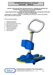
 User’s Product Manual LifeCore LC‐R100 Rower Introduction
Congratulations on your purchase of the LC-R100 Rower. This product has been designed and
manufactured to meet the needs and requirements for domestic and light commercial use.
By choosing the R100 rower, you have made a wise decision which will improve your health as well
as your families. Being fit and healthy will improve your energy level and your quality of life.
Cardiovascular training is vital for all ages and the R100 rower provides a more effective workout,
producing better results, and will encourage you to reach your fitness goals and maintain the body
you have always wanted.
In order to make your experience with LifeCORE the best it can be, please review the enclosed
user’s manual prior to assembly and first use. Be sure to keep the instructions for reference and/or
maintenance.
We also offer a complete line of fitness equipment; please take a moment to review our other
excellent products at www.LifeCOREfitness.com. Should you have any questions, please contact us.
Your feedback and ideas about your experience with LifeCORE are also very important to us.
Please write to us at:
LifeCORE Fitness Inc.
2575 Pioneer Ave. Suite 101
Vista, CA 92081
We wish you lots of success and fun while training!
Purchaser’s Reference Information
Serial Number is located on the frame
Please send in the attached warranty card and a copy of the original receipt or register online
at www.lifecorefitness.com within (10) days of purchase to register your product with
LifeCore Fitness.
Page 1
Table of Contents
Introduction…………………………………………………………………………………….............
1
Purchaser’s Reference Information ………………………………………………………………….
1
Table of Contents………………………………………………………………………………………
2
Safety Instructions and Warnings…………………………………………………………………….
3
Assembly Instructions………………………………………………………………………………….
4
Setting Up Your Rower ……………………………………………………………………………….
7
Correct Rowing Guide ………………………………………………………………………………...
12
Console Operation Instructions ………………………………………………………………………
15
Calculating Target Heart Rate ……………………………………………………………………….
23
Heart Rate Monitoring Devices……………………………………………………………………….
24
Care and Maintenance ……………………………………………………………………………….
25
Trouble Shooting ………………………………………………………………………………………
26
Parts List and Parts Diagram...……………………………………………………………………….
27
Warranty Card………………………………………………………………………………………….
29
Page 2 Safety Instructions & Warnings
The LC-R100 Rower is designed and manufactured to meet or exceed all domestic and international
safety standards; however, certain precautions need to be followed when operating any exercise
equipment.
General Safety Instructions:
1. It is important to consult your physician before beginning any exercise program.
2. Pregnant women should consult with their physician before beginning any exercise program.
He/she can help determine the exercise program that is the most appropriate for your age and
physical condition.
3. If you experience dizziness, nausea, chest pains or other abnormal symptoms during exercise,
stop the exercise session immediately. Consult your physician before continuing your exercise.
4. Keep children away from the equipment. Hands and feet may get caught in the pedals or other
moving parts, which could result in serious injury.
5. No more than one person should ever use the product at a time.
6. Pets should never be allowed near unit.
7. Always wear proper clothing and shoes when exercising. Drink plenty of fluids when exercising.
8. Always stretch and warm up before starting any exercise program.
9. Never operate this unit if it is damaged or broken. Contact your authorized dealer for service.
10. Place your equipment on a solid, level surface when in use.
11. Place your unit in an area with enough clearance to operate the equipment.
12. Make sure all components are fastened securely at all times.
Product Safety Instructions:
1. Start your exercise program gradually. Exercise only for a few minutes the first day to let your
body adjust to the new exercise.
2. Slowly increase your exercise time and intensity over the first two weeks. If you increase your
intensity too rapidly, or fail to warm up properly, you can increase the risk of injury.
3. Use of this machine with worn or weakened parts, may result in injury to the user. We strongly
suggest replacing it immediately. Use only the accessory attachments recommended by the
manufacturer.
4. Unit maximum weight limit is 600LBS
5. It is recommended the unit be plugged into a surge protector. Do not place machine in an area of
high voltage or electromagnetic fields.
6. Make sure that all components are fastened securely including but not limited to seat, pedals,
handlebars, or any electric components.
7. Never place any open containers of any type directly on the unit.
8. Keep machine clear of any obstructions, heavy machinery, and never place objects on or against
machine.
9. DANGER: Always unplug the power cord before performing maintenance.
10. Failure to follow these instructions will void the units warranty and the manufacturer or distributor
assumes no responsibility for personal injury or property damages related to the product if unit is
ever used incorrectly or for reasons other than exercise.
11. Perform proper maintenance as recommended in this manual.
Page 3 Assembly Instructions
Step 1: Unpackaging
Before assembling your product, distinguish a
proper and appropriate location for the unit.
Clear a big enough working space before
unpacking your LC-R100 Rower. Open the
carton as shown in the diagram below.
Unpackaged all loose components, double
check the packing materials to ensure no
missing parts were left behind.
Step 4: Foot Rest Assembly
Note: For SAFETY REASONS: Additional
assistance may be needed to help lift main
frame assembly to the upright position.
Tools Needed:
6mm Allen wrench
A. Turn the rower around to the upright
position as shown in the diagram below.
Step 4:
Step 2: Front Stabilizer Assembly
Note: For SAFETY REASONS: Additional
assistance may be needed to help turn main
frame assembly.
B. Remove and discard the red safety strap
holder from the pull strap. Place the
handlebar in the holder.
C. Remove the preassembled Qty. four bolts
(300) from the main frame with the
provided 6mm Allen wrench.
D. Locate the left and right foot rests; note
each one is individually marked with “L”
and “R” sticker. Assemble the Right (013)
and Left (014) foot rests to the main frame
with the same Qty. four bolts and tighten
bolts firm.
Tools Needed:
6mm Allen wrench
A. Turn the main frame (002) upside down in
the carton as shown in the diagram below.
B. Remove the preassembled Qty. four bolts
(300) from the main frame with the provided
6mm Allen wrench tool.
C. Locate the front stabilizer (005) and
assemble to the main frame, make sure the
wheels face forward. Use the same Qty.
four bolts to secure stabilizer and tighten
bolts firm with the 6mm Allen wrench.
Page 4 Step 5: Rear Stabilizer Assembly
Step 6: Rail Assembly
Tools Needed:
6mm Allen wrench
Note: For SAFETY REASONS: Additional
assistance may be needed to help lift rail on to
frame.
A. Locate the aluminum beam (001) and place
it on top of the carton lid as shown in the
diagram below.
B. With the tool provided, remove the
preassembled Qty. four bolts (300) from the
aluminum beam and Qty. two bolts (302)
from the rear stabilizer (006).
C. Position the rear stabilizer bar on the
aluminum beam. Secure the stabilizer to
the beam with the same Qty. four bolts
(300). Use the 6mm Allen wrench to tighten
bolts firm.
Tools Needed:
6mm Allen wrench
A. Remove the preassembled Qty. eight bolts
(300) from the die cast pivot (003) with the
provided 6mm Allen wrench.
B. Locate the assembled aluminum beam
(001) and gently slide the assembly onto
the main frame (003). Use the same Qty.
eight (300) bolts to secure beam to unit.
Use the 6mm Allen wrench to secure bolts
firm.
D. Slide the aluminum beam end cap (116) on
to the rear of the beam and rear stabilizer.
Screw in the Qty. two bolts (302) to the
frame. Use the 6mm Allen wrench to tighten
bolts firm.
E. With a pair of scissors gently cut the zip tie
holding the seat carriage. Discard the zip
tie.
Page 5 Step 7: Seat Assembly
Step 8: Seat Carriage Cover
Tools Needed:
6mm Allen wrench
Tools Needed:
Philips screw driver
A. Locate the seat (119) and remove the
preassembled Qty. 4 bolts (300).
A. Using the Philips screw driver on the
opposite side of the 6mm Allen wrench, and
remove the Qty. four bolts (303) from the
seat carriage.
B. Position the seat on the seat carriage and
screw in the Qty. four bolts (300).
Note: The pointed portion of the seat should
face forward.
C. Use the 6mm Allen wrench to secure bolts
into place.
B. Locate the two seat carriage covers (117)
and loosely screw the two cover into the
seat carriage using the Qty. four bolts (303).
Note: Ensure that the two seat carriage covers
(117) are engage correctly into each other as
shown in the diagram below.
C. Align the two covers together and make sure
they engage correctly. Finish tightening the
Qty. four bolts (303).
D. Discard and recycle the packaging material
and read the manual thoroughly before
using the rower.
Congratulations!
Assembly for the R100 Rower is complete.
Page 6 Setting Up Your Rower
Powering Unit
The R100 has the capacity to run on AC adaptor (ONLY USE A 6v 800mA Adaptor) or 4 C
batteries. To prevent damaged to the electronics, it is recommended to only use one power method
at a time with the R100 rower. Once a power source is connected, the computer will turn on
automatically. If unit goes into a “sleep mode” press any key or pull on the pull strap to activate
computer.
Note: Only use the appropriate power source, never use an adapter that is not certified for the unit, a
wrong adapter or bad batteries will cause the electronics to overheat and malfunction voiding the
warranty.
AC Adaptor Power
Attach the power cord jacket into the power socket on the main frame before plugging the power
cord plug into the wall outlet. Flip the ON/OFF switch to the ON position. "0" sign is for OFF; "I" sign
is for ON.
Battery Power
Remove the battery cover on the top of the fan and install four size C 1.5v batteries. Make sure that
the batteries are correctly positioned and properly installed. Reinstall the battery cover. Estimated
battery life is approximately three months under normal use; if the batteries are low, next to the pulse
display a battery symbol will flash when they need to be replaced.
Note: Never mix old and new batteries and never mix different brand of batteries. If unit is going to
be stored for a long period of time, it is mandatory to remove the batteries to prevent damaging the
electrical system.
Note: Display sleep mode: If user stops rowing and there is no RPM or pulse detected for 4 minutes,
the display will shut down and enter a “sleep mode.” To resume, simply press a button on the
console or begin to row. User work out data will be stored in the computer for up to 10 minutes, if
user does not return to work out within this time all data readouts will return to 0.
Page 7 Unfolding the Rail
1) Loosen Clamp Knob: (Image 1) While the rower is in the folded position, rotate the clamp knob
(125) counter-clockwise five to seven turns.
2) Lowering the Beam: (Image 2 & 3) Position one hand on the aluminum beam (001) while the
other hand pulls down on the clamp knob to release the safety lock. This will allow the aluminum
beam to lower flat.
3) Tighten Clamp Knob: (Image 4) While the rower is in the flat position, rotate the clamp knob
clockwise to lock beam in place.
WARNING: Never attempt to lower the beam by yourself, ask for additional help if needed and never
attempt to lift the beam if you have any medical issues.
To avoid serious injury, keep finger and hands away from the folding hinge points
Folding the Rail
1) Loosen Clamp Knob: (Image 1) While the rower is in the flat position, rotate the clamp knob
(125) counter-clockwise five to seven turns.
2) Lifting the Beam: (Image 2 & 3) Position one hand on the aluminum beam (001) while the other
hand pulls down on the clamp to release the safety lock. This will allow the aluminum beam to
fold up.
3) Tighten Clamp Knob: (Image 4) While the rower is in the folded position, rotate the clamp knob
clockwise to lock beam in place.
Page 8 Sitting Down
1) Position yourself in the middle of the aluminum beam (001).
2) Grab the seat assembly and position it below yourself.
3) With one hand on the seat assembly and one hand on the aluminum beam, slowly sit down.
Heel Support Adjustment
1) Squeeze the heel support levers on each side to release the locking mechanism.
2) While squeezing the heel support levers slide the heel support to desired setting. (Number on
the top of the heel support levers is the number that will be set. As illustrated below, adjust the
heel support to allow the foot strap to be across the top of the foot just below the toes.
3) Release the heel support levers to engage the locking mechanism.
Page 9 4) Adjust the strap by pushing down on the strap release tab, and pull on the inner strap to loosen.
5) Once the foot is properly positioned, pull on the strap to tighten foot securely to foot pedals.
Computer Angle Adjustment
The computer (714) and computer arm (015) is designed to pivot and adjust to accommodate to
almost any users height and view preference.
1) As illustrated below, hold the computer with both hands. Rotate and pivot the computer to the
desired height and angle.
Note: For safety reasons, while exercising avoid the drive strap (709) from touching the computer.
Air Vent Adjustment
The rower’s flywheel fan generates an air flow that can be directed with the adjustable air vent.
1) Rotate the air vent control knob to adjust the air flow direction.
2) To stop all air flow, rotate the air vent control knob down to prevent air from flowing towards you.
Page 10 Handle Bar Holder
When you have finished your workout remember to store the handle bar into the handle bar holder
(108) as shown in the diagrams below
Transportation and Storage
1) Before transporting the rower, make sure the aluminum beam (001) is in the folded position.
(Reference Folding the Rail section)
2) As illustrated below, tilt the rower forward until the front transportation wheels are touching
the ground. You may now move the machine to the desired location. After the move, gently
set the machine down at its new location
WARNING: Never attempt to move the R100 by yourself, ask for additional help if needed and
never attempt to lift the machine if you have any medical issues.
Page 11 Correct Rowing Guide
Over Reaching
Fault
Stretching the back or the body is stretched too far forward. (Sore Back)
Solution
Always keep your back as straight as possible; pull and push with your legs and arms instead. Do
not use your back to pull the pull strap out.
Rowing with Arms
Fault
Rowing by pulling the pull strap out with the arms first. (Sore Arms)
Solution
Keep arms straight until legs are about to be fully extended, pulling the remaining strap with your
arms towards the body.
Page 12 Bent Wrists
Fault
Pulling out the pull strap with the wrist or bent hands. (Sore Forearms)
Solution
Keep wrists and arms straight at all times. Always rows with flat wrists through the entire stroke.
Pulling the Body to the Handle
Fault
Pulling the body towards the pull strap or crunching forward. (Sore Back, Abs)
Solution
Use the arms to pull the pull strap towards the body. Keep the back straight during the entire row.
Page 13 Elbows too High
Fault
Elbows are sticking out from the body at the finish and the handle is at chest level. (Sore Arms)
Solution
Pull the pull strap towards the middle of the body. The wrists are flat and the elbows are pulled back
towards the body.
Locking the Knees
Fault
At the end of the stroke, the user locks the knees making the legs straight. (Sore Knees)
Solution
Always keep the legs slightly bend while in the fully extended position. Do not lock the knees.
Page 14 Console Operation Instructions
Please read the console operating instruction thoroughly and familiarize yourself with the console
layout before choosing a workout. Going through the console first will give you ideas to the type of
workout possibilities you can choose from. Below is the console layout and detailed operation
instructions.
Make sure the R100 is powered-up before you start using this console. This product is powered by
AC power (ONLY USE A 6v 800mA) or 4 C batteries. Please use only one power method at a time.
Make sure the power cord is properly plugged into the machine and wall outlet and/or batteries are
properly enauged. Turn the AC power switch to the ON position. Press any button or pull on the pull
strap to activate console.
1.
CONSOLE LAYOUT
Message Display Window Dot Matrix Profile Window Data Display Windows Data Display Windows Function Keys Page 15 2.
DISPLAYS
A.
Dot Matrix Profile Window: Displays program profile during program setting and executing.
The program profile will change according to which program is selected.
For resistance profile display: There are 20 columns of LCD representing 20 segments of time; each
segment time = total program time divided by 20 columns. During exercising, a column of LCD will
blink to indicate the time segment you are currently in and show your workout progress.
There are also 8 rows of LCD representing 16 levels of resistance. Each row represents 2 levels of
resistance. The appropriated row of LCD will light up when you adjust the resistance level. In
addition the level of resistance will display in the data display window under the level display.
B.
Data Display Windows: There are 10 data display windows displaying user, level, SPM
(Stokes Per Minute), pulse, time/500M, watts, time, strokes, meters and calories. During program
setting, the appropriated data window will blink to indicate which data you are currently setting.
Rotate the SELECT dial to adjust the value then press the ENTER key to confirm the value.
Note: Setting a number other than 0 in those display windows will count the number down. If data
display setting is set at 0, the reading will count up.
Data Display Readouts:
I.
USER: Indicates which user profile is being utilized during a program (U1-U4).
II.
Level: Displays the amount of resistance during a workout, levels 1 – 16 magnetic tension.
III.
SPM: Strokes Per Minute shows the estimated amount of strokes pulled during one minute if
speed is maintained at that current pace. Number will fluctuate as pull speed changes.
IV.
PULSE: If a wireless heart rate strap is used, will display a user’s heart rate.
V.
Battery Symbol: If batteries are being used to power unit, next to the pulse display a battery
symbol will flash when they need to be replaced.
VI.
TIME/500M: Is the measurement of speed generally known as the "split time" or the amount
of time in minutes and seconds required to travel 500 meters at the current pace.
VII.
WATTS: Displays the estimated watts per stroke during a workout.
VIII.
TIME: Measures time in minutes and seconds 0 – 99:00min
IX.
STROKES: Displays the total amount of strokes pulled during a workout.
X.
METERS: Represents the distance traveled during a workout. (0 - 99,990 meters) Meters is
the basic unit of measurement in the metric system and is slightly longer than 1 yard.
XI.
CALORIES: Measured in kilocalories displays the estimated amount of calories burned.
C.
Message Display Window: Will display the program name during program selection and
program executing; program setting instruction and user setting instruction.
Note: Display sleep mode: If user stops rowing and there is no RPM or pulse detected for 4 minutes,
the display will shut down and enter a “sleep mode.” To resume, simply press a button on the
console or begin to row. User work out data will be stored in the computer for up to 10 minutes, if
user does not return to work out within this time all data readouts will return to 0.
Page 16 KEYS: There are 5 function keys for program operation.
A.
START/STOP Key: Pressing the START/STOP key once will start the program and all data
will begin to count. Press the START/STOP key again to stop the computer program. To resume,
simply press START/STOP one more time to start program. Press & hold START/STOP key for a
couple of seconds to reset the console back to program selection mode. All previous recorded value
such as: time, strokes, meters, calories, etc. will be reset to 0.
B.
ENTER Key: Press ENTER key to confirm the program setting, selection or data entry.
C.
SELECT Dial: Rotate the SELECT dial to go to the next user profile setting; next program
selection; to adjust data entry during program setting or to increase level resistance during program
execution.
D.
USER Key: This key is to select between 1 – 4 user profiles.
E.
RECOVERY Key: This is a function designed to see how much time it takes for the heart to
recover after a workout and therefore recommends a fitness level. The program will take 60 seconds
to figure out your fitness level and present a fitness score. Note: A heart rate pulse has to be read
before and during for this function to work.
Press the RECOVERY key after a workout, the time display will start counting down from 60
seconds and pulse display will display your current heart rate. Do not press any key or exercise
during the 60 second period. After 60 seconds, the dot matrix display will show your fitness score.
Fitness Level vs. Score Chart
Score
F1
F2
F3
F4
F5
F6
Fitness Level
Excellent
Good
Fit
Average
Below Average
Challenge
Changing User Measurement Reading from Metric to Imperial (SI)
If you press and hold the START/STOP and ENTER button at the same time for a few seconds, it
will allow you to change user measurement readings from metric to imperial. Use the SELECT dial to
rotate to METRIC or IMPERIAL, then press the enter key to confirm selection. This will not change
the distance measurement.
Note: Switching between measurements will zero out all preexisting user information.
3.
PROGRAMS
A.
User Profile: Before picking a program, it is recommended to set up your user profile. It will
ensure workout data calculations are more accurate and future workouts are more convenient.
There are four user spaces U1 – U4 to save user information, there is one profile for each user who
Page 17 will be using the machine. User profile information such as height, weight, age, gender information
and user profile programs will be saved permanently in each profile unless a user changes them.
Setting Up User Profiles:
Step 1: Select User Number: Power up the console press the USER button to enter user profiles.
Rotate the SELECT dial to choose a user profile U1 - U4. Data display window will show the
selected user profile number, such as U1. Press the ENTER key to confirm selected user.
Step 2: Setup User Height: Default reading of 175cm or 5’ 09” inches and/or last entered height will
appear on the dot matrix window. Rotate the SELECT dial to adjust the height and press the ENTER
key to confirm selected height. The range of height is 110 – 250cm or 3’08” – 8’00” inches.
Step 3: Setup User Weight: Default reading of 70.0kgs or 155 lbs and/or last entered weight will
appear on the data display window. Rotate the SELECT dial to adjust the weight and press the
ENTER key to confirm selected weight. The range of weight is 10 – 200kgs or 23 – 440lbs.
Step 4: Setup User Age: Default reading of 30 years of age or last entered age will appear on the
data display window. Rotate the SELECT dial to adjust the age and press the ENTER key to confirm
selected age. The range of age is 10-99 years.
Step 5: Setup User Gender: M (male) or F (female) abbreviation will light up. Rotate the SELECT
dial to change selection and press the ENTER key to confirm selected gender.
After Gender is selected, the user profile setup is complete and user information will be saved into
selected user number permanently. To change the user information, simply go through the setup
process and enter a different value. Press the START/STOP button to enter program selection.
B.
Program Selection: There are 11 programs to choose from: Manual, White Water, Ramp,
Pacer, Intervals- distance, Intervals- time, User Profile, Watts Control and 3 Heart Rate Control
Programs. The program name will be displayed on the message window and program profile will be
displayed on the dot matrix window. Rotate the SELECT dial to select a desired program and
ENTER to confirm.
Note: After program is selected, you can press START/STOP anytime to jump start the program with
preset value. The console will use default values or previous entered value to start the program.
C.
Manual Program: Is designed to be a basic quick start program having a default resistance
level of 6. This program maintains a level resistance during the entire workout unless the resistance
is adjusted by using the SELECT dial to increase or decrease it.
I.
Manual Programming: When the SELECT dial is rotated during the category selection mode
to “MANUAL” press the ENTER to confirm selection.
1. Choose Meter Distance: A default 5,000 meters will display in the data display window and
this number can be changed by increments of 100 by using the SELECT dial to adjust
between ranges of 0 - 99,990 meters. Press the ENTER key once selection is complete.
Page 18 2. Choose Time: A default 30:00 min will display in the data display window and this number
can be changed by increments of 1 min by using the SELECT dial to adjust between ranges
of 0 – 99:00min. Press the START/STOP button, start rowing and time and data display
windows will start to count.
D.
White Water & Ramp Programs:
These are preset profile programs that will adjust the magnetic resistance automatically as you
progress through the profile program.
Note: Resistance level 6 “WHITE WATER” and resistance level 4 “RAMP” will be the default tension
setting and these levels can be adjusted at anytime to increase or decrease resistance.
II.
WHITE WATER & RAMP Programming: When the SELECT dial is rotated during the
category selection mode to “WHITE WATER or RAMP” press the ENTER to confirm selection.
3. Choose Meter Distance: A default 5,000 meters will display in the data display window and
this number can be changed by increments of 100 by using the SELECT dial to adjust
between ranges of 0 - 99,990 meters. Press the ENTER key once selection is complete.
4. Choose Time: A default 30:00 min will display in the data display window and this number
can be changed by increments of 1 min by using the SELECT dial to adjust between ranges
of 0 – 99:00min. Press the START/STOP button, start rowing and time and data display
windows will start to count.
E.
Pacer Program:
The Pacer program also know as a “RACE” program allows a user to row beside or race against a
pace boat. This program is a friendly competitive program that will help keep workouts different and
challenging as you try to maintain or beat the pace boat. On the dot matrix display, a virtual boat will
display indicating each other’s progress. In the data display window, the computer will let you know
how many meters you are “AHEAD, EQUAL, or BEHIND” against the pace boat.
Note: Resistance level 1 will be the default setting and this level can be adjusted at anytime.
III.
Pacer Programming: When the SELECT dial is rotated during the category selection mode
to “PACER” press the ENTER to confirm selection.
5. Choose Meter Distance: A default 5,000 meters will display in the data display window and
this number can be changed by increments of 100 by using the SELECT dial to adjust
between ranges of 0 - 99,990 meters. Press the ENTER key once selection is complete.
6. Choose Time: A default 30:00 min will display in the data display window and this number
can be changed by increments of 1 min by using the SELECT dial to adjust between ranges
of 0 – 99:00min. Press the START/STOP button, start rowing and time and data display
windows will start to count.
Page 19 F.
Intervals programs:
There are two types of Interval programs on the R100, Intervals- distance and Intervals- time. The
difference between these two programs is in the “INTERVALS-DISTNCE” program, you select a
work distance and in the “INTERVALS-TIME” program you select a work time.
Interval programs combine short and high intense workouts followed by a short recovery phase;
which are repeated in a series of repetitions completed or intervals to help build speed, endurance
and can also provide a more efficient fat burning workout. Interval training works both the aerobic
and anaerobic systems more efficiently, yet can be extremely demanding. It is suggested to start
with a short interval work out of 30 sec. - 1:00min workouts followed by an equal amount of rest time
in between intervals until endurance is built.
IV.
Intervals-Distance Programming: When the SELECT dial is rotated during the category
selection mode to “INTERVALS-TIME” press the ENTER to confirm selection.
1. Choose Interval Distance Workout: A default 100 meters will display in the data display
window and this number can be changed by increments of 100 meters by using the SELECT
dial to adjust between ranges of 100 – 99,900 meters. Press the ENTER key once selection
is complete. Note: Meters will count down.
2. Choose Interval Rest Time: A default 30 sec. will display in the data display window and this
number can be changed by increments of 10 sec by using the SELECT dial to adjust
between ranges of 0:00 – 9:50min. Press the ENTER key once selection is complete.
Note: Meters will count up.
3. Choose Amount Of Intervals: A default amount of 10 intervals will display in the dot metric
profile window and this number can be changed by increments of 1 workout (1-10). Press the
START/STOP button, start rowing.
V.
Intervals-Time Programming: When the SELECT dial is rotated during the category
selection mode to “INTERVALS-TIME” press the ENTER to confirm selection.
1. Choose Interval workout Time: A default 1:00 min will display in the data display window
and this number can be changed by increments of 10 sec by using the SELECT dial to adjust
between ranges of 20 sec. – 99:50min. Press the ENTER key once selection is complete.
Note: Meters will count down.
2. Choose Interval Rest Time: A default 30 sec. will display in the data display window and this
number can be changed by increments of 10 sec by using the SELECT dial to adjust between
ranges of 0:00 – 9:50min. Press the ENTER key once selection is complete. Note: Meters will
count down.
3. Choose Amount Of Intervals: A default amount of 10 intervals will display in the dot metric
profile window and this number can be changed by increments of 1 workout (1-10). Press the
START/STOP button, start rowing.
Note: A default resistance level of 8 will be automatically adjusted at the start of the program,
resistance can be manually adjusted at anytime, and the computer will not change resistance
between workout and rest periods.
Page 20 G.
User Profile Program: This program is designed for user’s to build the program profile
segment by segment “resistance level” before exercising. It provides endless possibilities to keep
you motivated. Once you build your unique profile, it will be stored under the associated user
number permanently. Each user number can store one program profile.
After you enter your targets for this program, the message display will take you one column at a time
to build your profile.
Note: Only “chosen level” will be permanently saved in user profile information. Resistance can be
changed at anytime while the program is being executed.
VI.
User Profile Programming: When the SELECT dial is rotated during the category selection
mode to “USER PROFILE” press the ENTER to confirm selection.
1. Choose Meter Distance: A default 5,000 meters will display in the data display window and
this number can be changed by increments of 100 by using the SELECT dial to adjust
between ranges of 0 - 99,990 meters. Press the ENTER key once selection is complete
2. Choose Time: A default 30:00 min will display in the data display window and this number
can be changed by increments of 1 min by using the SELECT dial to adjust between ranges
of 0 – 99:00min. Press the ENTER key once selection is complete
3. Column Level: A default resistance level of 1 will display in the data display window. Use
the SELECT dial to adjust level. Press the ENTER key to confirm level. The message display
will take you one column at a time to build your profile. (Column 1 – 20) Once you get to
column 20, press the START/STOP key, start rowing and time and data display windows will
start to count.
Note: Press the START/STOP key at anytime during the column selection to begin program, but
note the remaining segments will start with resistance level 1.
H.
WATTS Control Program:
Watt (power) is determined by speed & resistance. This program is designed to let you set up your
watt goal. The console will automatically adjust the resistance level according to your speed to
maintain your watt goal. The watt value can be set from 30 – 300.
Note: Resistance control will automatically adjust; manual resistance adjustment is disabled during
watt program.
I.
Watt Control Programming: When the SELECT dial is rotated during the category selection
mode to “WATTS CONTROL” press the ENTER to confirm selection.
1. Choose Meter Distance: A default 5,000 meters will display in the data display window
and this number can be changed by increments of 100 by using the SELECT dial to adjust
between ranges of 0 - 99,990 meters. Press the ENTER key once selection is complete.
2. Choose Time: A default 30:00 min will display in the data display window and this number
can be changed by increments of 1 min by using the SELECT dial to adjust between
ranges of 0 – 99:00min. Press the ENTER key once selection is complete.
Page 21 3. Choose Watt: A default watt of 100 will display in the data display window. Use the
SELECT dial to adjust watt. Press the START/STOP button, start rowing and time and
data display windows will start to count.
I.
60%; 75% & 85% Max Heart Rate Control Programs: H.R.C. programs are based off of
user profile information (AGE). Heart rate control programs are designed to keep you training at your
chosen heart rate level. The console will adjust the resistance level automatically to ensure the
target heart rate is achieved and maintained during the entire program. Your target heart rate, the
intensity needed to improve cardiovascular fitness, depends primarily on your age and not your state
of fitness. It is calculated as a percentage of your maximum heart rate, estimated as 220 minus your
age. It is most effective to train at your target heart rate between 60% and 85% of your maximum
heart rate. In order to get the most accurate reading, it is recommended to enter your age before
your workout in the user profile.
Example: 220 - (Age 45) = 175 X multiplied by (60% or 75% or 85%) (Percentage 60%) = 105 bpm
Note: A heart rate monitoring device must be used for the program to work. The computer will adjust
resistance automatically or manually increase resistance to reach maximum level quicker. It is also
important to consult your physician before performing any heart rate based training program.
Note: Only a 5k heart rate transmitter will work with the R100 rower. If there is no heart rate detected,
the message display window will show “NO SIGNAL.”
I.
Quick Start: When the SELECT dial is rotated during the category selection mode to one of
the three H.R.C. programs, and if the correct user number is displayed in user data display
window, simply press the START/STOP button. Start rowing and time and data display
windows will start to count. Rotate the adjustment dial to adjust resistance level.
II.
H.R.C Programming: When the SELECT dial is rotated during the category selection mode
to one of the three H.R.C. programs; press the ENTER key to enter that desired H.R.C.
program.
1. Choose Meter Distance: A default 5,000 meters will display in the data display window
and this number can be changed by increments of 100 by using the SELECT dial to
adjust between ranges of 0 - 99,990 meters. Press the ENTER key once selection is
complete.
2. Choose Time: A default 30:00 min will display in the data display window and this
number can be changed by increments of 1 min by using the SELECT dial to adjust
between ranges of 0 – 99:00min. Press the ENTER key once selection is complete.
3. Choose Age: A default age of 30 will display in the data display window, last selected
age range or age of user profile information being used. Use the SELECT dial to adjust
age. Press ENTER key to see the target heart range, use the SELECT dial to adjust heart
rate if the calculation is not the desired heart rate range. Press the START/STOP button,
start rowing and time and data display windows will start to count. Rotate the adjustment
dial to adjust resistance level.
Page 22 Calculating Target Heart Rate
In order to obtain the greatest cardiovascular benefits from your exercise workout, it is important to
work within your target heart rate zone. The American Heart Association defines this target as 60%85% percent of your maximum heart rate.
Your maximum heart rate may be roughly calculated by subtracting your age from 220. Your
maximum heart rate and aerobic capacity naturally decreases as you age. This will vary from one
person to another. Use this number to find your approximate effective target zone. It is most effective
to train at your target heart rate between 60% and 85% of your maximum heart rate; referred to as
“Training Zone”. In order to get the most accurate reading, it is recommended to enter your age
before your workout.
Before beginning your workout, check your normal resting heart rate. Place your fingers lightly
against your neck or against your wrist over the main artery. After finding your pulse, count the
number of beats in 10 seconds. Multiply the number of beats by six to determine your resting pulse
rate per minute. We recommend taking your heart rate at these times; at rest, after warming up,
during your workout and two minutes into your cool down, to accurately track your progress as it
relates to better fitness.
During your first several months of exercising, the AHA recommends aiming for the lower part of the
target heart rate zone-60%, then gradually progressing up to 75%. According to the AHA, exercising
above 85% of your maximum heart rate may be too strenuous unless you are in top physical
condition. Exercising below 60% of your maximum will result in minimal cardiovascular conditioning.
Check your pulse recovery rate – If your pulse is over 100bpm five minutes after you stop exercising,
or if it’s higher than normal the morning after exercising, your exertion may have been too strenuous
for your current fitness level. Rest and reduce the intensity level of the next exercise.
Fitness Safety: The Heart Rate chart indicates average heart rate zones for different ages. A
variety of different factors (including medication, emotional state, temperature and other conditions)
can affect the target heart rate zone that is best for you. Your physician or health care professional
can help you determine the exercise intensity that is appropriate for your age and condition.
Page 23 Heart Rate Monitoring Devices
Chest Strap
The R100 is equipped with a built-in wireless 5k receiver for your heart rate monitoring transmitter.
Please contact your dealer to purchase a compatible 5k chest strap transmitter, if you would like to
use more wireless heart rate features.
To get an accurate reading using these devices, you will need to be within three feet of the console,
and a minimum of four feet from others using a heart rate monitoring device.
The receiver of the wireless ECG system is built into the console unit.
How to Wear Your Sensor/ Transmitter:
(1)
(2)
(3)
(4)
(5)
Buckle one end of the chest strap onto the transmitter.
Adjust the band length so that the fit is snug, but not too tight.
Buckle the other end of the chest strap onto the transmitter
Center the transmitter on your chest below the pectoral muscle (breasts).
Stretch the transmitter away from your chest and moisten the conductive electrode strips located
next to the buckles with water.
Note: The transmitter is on automatically when it is being worn. It is off when it is not connected to
your body; however, as moisture may activate the transmitter, thoroughly dry the transmitter after
every use to prolong battery life.
Chest Strap Troubleshooting: No heart rate reading
9 If transmitter was just strapped on, wait a few minutes so that the transmitter gets a good connection
with your body. When you start to sweat the connection will improve.
9 While wearing the transmitter, adjust the strap to get a different position.
9 Check that the elastic strap is tight enough around your body.
9 Check that the electrodes on the transmitter are moistened properly.
9 Check that the transmitter electrodes are clean.
9 Check to see if battery is still working. The estimated average battery life of the transmitter is 600
hours of use. If the battery of the transmitter is running low, the transmission range decreases and
may cause errors similar to the ones listed above.
Page 24 Care and Maintenance
The LifeCORE R100 is made from the best materials and has been tested and received a quality
control review prior to its packaging to ensure the correct parts and proper fitting of each component.
The amount of maintenance required is very little and very simple; however, a failure to implement
preventative maintenance suggestions can prevent the machine from operating as designed. The
R100 is only for indoor use and should not be stored outside or damp, extremely cold or hot areas
as this will damage the unit voiding the warranty.
For safety reasons, inspect your rower on a regular basis. When used in a light commercial
environment safety check every day.
Rules:
¾ Never use WD-40 or any type of silicone spray to lubricate any moving parts. Use of this
type of lubricating will damage the unit’s components voiding the warranty.
¾ Always clean the machine after use. (Rail, Seat, Handlebar)
1) Proper cleaning is important for longevity of a machine, clean the unit with a light soap
water mixture, followed by a dry towel. You can also use a light house hold cleaner
such as Windex to remove dirt and sweat. The purpose of cleaning the unit is to remove
body sweat from the unit which contains salt. Salt is the number one factor that will
cause the unit to rust and the electronics to stop working.
2) Dry the unit off with a clean towel to remove left over moisture after every use.
9 After the first 12 hours of use, check and retighten any bolts, nuts, screws, pedals, etc.
making sure that they are tight and working properly.
1) The number one service issue is loose hardware. Loose hardware can cause the unit to
tick, creak, thump, knock, etc. After the first 12 hours once all the hardware has been
tightened, the hardware should be checked every 3 months.
9 Only use the appropriate power source, never use an adapter that is not certified for the unit,
a wrong adapter will cause the electronics to overheat and malfunction voiding the warranty.
6V 800mA adaptor
In the unlikely event that the R100 experiences a problem, please contact LifeCORE fitness for
advice toll free at 888-815-5559.
Page 25 Trouble Shooting
1. Issue: Clicking or knocking sound from seat
9 Check wheels on seat rail for cracks.
9 Clean wheels and rail to allow wheels to roll smooth. Use Windex and a paper towel to
remove any dirt build up on rail and wheels.
9 Check to see if wheels are tight.
9 Adjust the tension of the seat roller (Part # 142).
2. Issue: Display is not powering on
9 Check to see if AC adaptor is 6V 800mA. If a different voltage adaptor was used, electronics
were probably shorted out.
9 Check to see if AC adaptor switch is turned to the ON position.
9 Check to see if cable on adaptor or AC inlet connection on the machine is not damaged.
9 If unit is being powered by batteries, replace batteries.
9 If unit is still not powering on, replace computer.
3. Issue: Motor is clicking
9 Check tension on motor cable. Loosen or tighten tension cable to allow motor to move
smoother.
9 If motor is still clicking, motor will need to be replaced.
4. Issue: Pull strap is slipping
9 Tighten tension bolt # 311 to tighten drive belt part # 134.
9 If belt is still slipping, strap drum assembly will need to be replaced.
5. Issue: Grinding noise when pull strap is pulled
9 Check to see if any screws, bolts are trapped in the magnetic flywheel.
9 Check to see if a magnet fell off.
9 Check to see if tension cable did not snap.
6. Issue: Rail in not staying in folded position
9 Check that the adjustment knob # 125 engages properly and is not damaged.
9 Check to see if part # 003 is not damaged.
7. Issue: ERROR 1
9 Unplug power source for a few seconds, then reconnect power.
9 If unit does not reboot, there is a motor error and motor will need to be replaced.
8. Issue: ERROR 2
9 Unplug power source for a few seconds, then reconnect power.
9 If unit does not reboot, there is a software failure and computer will need to be replaced.
Page 28 Parts List & Parts Diagram
Page 29 Page 30 Warranty Card
Limited Consumer Warranty
LifeCORE Fitness Inc.
LC-R100 Rowing Machine
What is Covered. LifeCORE Fitness, Inc. (“LifeCORE”) warrants to the original purchaser of this LifeCORE Fitness
branded product (the “Product”) that the frame of the Product shall be free from defect in materials and
workmanship during the normal life of the Product and all other part and components of the Product shall be free
from defect in material and workmanship for a period of 5 years when the Product is used under as recommended
by LifeCORE under normal family household uses and conditions. Light-Commercial: 2 Year Parts warranty against
manufacturer defects. During the warranty period LifeCORE will at no additional charge to you, repair or replace
(at LifeCORE option) the frame or any part of the Product if it becomes defective, malfunctions, or otherwise fails to
conform with this Limited Warranty. All labor for any required repair is warranted for 1 Year from the date of original
purchase or Light-Commercial 90 days Labor. After 1 year or 90days all labor shall be the responsibility of the owner.
What is Not Covered. This Limited Warranty applies only for Product sold in the United States under the LifeCORE
brand name. This warranty does not cover normal wear and tear on items such as, but not limited to, transportation
wheels, foot pedals, rubber grips, plastic end caps, scratched parts, broken covers, cosmetic damage, and
excludes paint & finish. Wear items pertain to components that might need to be replaced due to wear and tear
resulting from normal usage. This warranty is void if the Produce is improperly stored, installed, altered and/or
modified in any way, misused, abused, is subject to accident, is improperly maintained, and this warranty does not
cover repair for any noises such as: squeaks, clunks, thumps resulting from poor or lack of preventive maintenance.
This Limited Warranty does extent to any Product that is damaged or rendered defective; (a) as a result of accident,
misuse, or abuse; (b) use with the Product of any part not manufactured or sold by LifeCORE; (c) by modification of
the Product; (d) by normal wear and tear; (e) operation using incorrect power supplies; or (f) as a result of service
by anyone other than LifeCORE, or an authorized LifeCORE service provider. This Limited Warranty is void if the
Product serial number has been defaced or removed. Should any Product be submitted for warranty service be
found ineligible, an estimate of repair cost will be furnished.
Warranty Service Area. Any labor cost above the amount allocated by LifeCORE is the responsibility of the original
purchaser. If a Product requires shipment, delivery or transport to an area that is not within a LifeCORE distribution
area or is outside of a serviceable area is the purchaser’s sole responsibility and to pay for any fees associated with
servicing of a Product out of LifeCORE Fitness distribution or serviceable area. Any evidence of alteration, erasing or
forgery of proof-of-purchase documents voids this Limited Warranty. This Limited Warranty applies only to Product
purchased from LifeCORE or from an authorized LifeCORE reseller.
Disclaimed Warranties. TO THE MAXIMUM EXTENT ALLOWED BY LAW, ALL WARRANTIES, INCLUDING BUT NOT LIMITED
TO EXPRESS WARRANTY, IMPLIED WARRANTY, WARRANTY OF MERCHANTABILITY, FITNESS FOR PARTICULAR PURPOSE
AND WARRANTY OF NON-INFRINGEMENT OF INTELLECTUAL PROPERTY, ARE EXPRESSLY EXCLUDED TO THE MAXIMUM
EXTENT PERMITTED BY LAW; AND LIFECORE NEITHER ASSUMES NOR AUTHORIZES ANY PERSON OR ENTITY TO ASSUME
FOR IT ANY DUTY, OBLIGATION OR LIABILITY IN CONNECTION WITH ITS PRODUCTS. LIFECORE HEREBY DISCLAIMS AND
HAS ABSOLUTELY NO LIABILITY FOR ANY AND ALL ACTS OF THIRD PARTIES INCLUDING DEALERS OR INSTALLERS. IN THE
EVENT OF A CLAIM OR A DISPUTE INVOLVING LIFECORE OR ITS SUBSIDIARY, THE PROPER VENUE SHALL BE SAN DIEGO
COUNTY IN THE STATE OF CALIFORNIA. CALIFORNIA STATE LAWS AND APPLICABLE FEDERAL LAWS SHALL APPLY AND
GOVERN THE DISPUTE. THE MAXIMUM RECOVERY UNDER ANY CLAIM AGAINST LIFECORE SHALL BE STRICTLY LIMITED TO
THE PURCHASE PRICE OF THE PART. LIFECORE SHALL NOT BE RESPONSIBLE FOR ANY DAMAGES WHATSOEVER,
INCLUDING BUT NOT LIMITED TO, ANY CONSEQUENTIAL DAMAGES, INCIDENTAL DAMAGES, DAMAGES FOR THE LOSS
OF TIME, LOSS OF EARNINGS, COMMERCIAL LOSS, LOSS OF ECONOMIC OPPORTUNITY AND THE LIKE.
Some states do not allow limitations on how long an implied warranty will last or the exclusion or limitation of
incidental or consequential damages. This warranty gives you specific legal rights and you may also have other
Page 31 rights that vary from State to State. LifeCORE does not and has not authorized any person or entity to create for it
any other obligation, promise, duty or obligation in connection with this Product.
Warranty Registration. PLEASE SEND IN THE ATTACHED WARRANTY CARD WITHIN (10) DAYS OF PURCHASE TO
REGISTER YOUR PRODUCT WITH LIFECORE FITNESS. PLEASE MAIL WARRANTY CARD TO: LIFECORE FITNESS, INC, 2575
Pioneer Ave. Suite 101. Vista, CA 92081. Phone (760)599-4555, Fax (760) 946-7602 or register online at
LifeCOREfitness.com, Customer Service: 888-815-5559. Unless otherwise prohibited by law, in order to validate the
warranty this Product must have been registered through LifeCORE Fitness Inc., and/or a copy of the proof of
purchase, and serial number must be presented at time of service. If these items are not presented at the time of
requesting parts or service LifeCORE Fitness Inc. will not cover any warranty.
Warranty Claim Processing. To obtain warranty service, you must contact the original place of purchase. LifeCORE
may at its option may repair or replace any defective Product frame or parts with new or serviceable used parts
that are equivalent in function to the original parts. All exchanged frames and parts replaced under this warranty
will at the time of service become the property of LifeCORE. LifeCORE reserves the right to change manufacturers
of any parts to cover any existing warranty. Any parts determined to be defective must be returned to LifeCORE to
obtain warranty service. You must prepay any shipping charges, export taxes, custom duties and taxes, or any
other charges associated with transportation of the parts or Product. In addition, you are responsible for insuring
any parts or Product shipped or returned. You assume the risk of loss during shipment.
Please see other LifeCORE Fitness Products at www.LifeCOREfitness.com.
THANK YOU FOR YOUR BUSINESS!
LC-R100 Rowing Machine
Please Attach a Copy of the Original Receipt
Full Name: _______________________________________________________________________ Address: ________________________________________________________________________ City: ______________________State: ________ Zip Code: ________________________ Daytime Phone No.:_______________ Cell Phone No.:___________________________ Email: ________________________________________________________________________ Dealer Purchased from: ____________________________________________________ Model: LC‐R100 Rower_____________ Date Of Purchase: _______________________ Serial No._____________________________________ Environment Placed: Residential Light Commercial Commercial Customer Service Toll Free (888) 815‐5559 Mon‐Friday 7:30 ‐ 5:30 PT [email protected] Lifecore Fitness Inc. 2575 Pioneer Ave. Suite 101 Vista, CA 92081 Visit our website for assembly videos: www.lifecorefitness.com