1
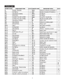
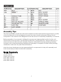
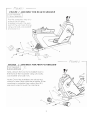
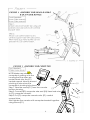
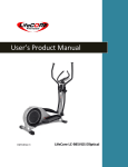
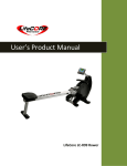
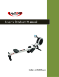
LC 850 RB
User Product Manual
LifeCore LC-850 Recumbent
Customer Service
Toll Fee (888) 815 – 5559
[email protected]
www.lifecorefitness.com
LifeCore Fitness Inc.
2575 Pioneer Avenue, Suite 101,
Vista, CA 92081
1
Visit our website for assembly videos: www.lifecorefitness.com
Important Safety Instruction
We at LifeCore fitness would like to thank you for your recent purchase of a LifeCore exercise
bike, and we hope that our product inspires and motivates you to accomplish your fitness goals.
Please read the users owners manual and orient yourself with the unit before you use the
product to get a better understanding of your exercise machine.
The LifeCore 850RB is an exercise bike that simulates the movements of riding a bicycle at
different speeds and resistance levels. Before the machine is ever used, it is recommended that
a physician be consulted regarding any user(s) health condition, especially if the user(s) has a
family history of cardio vascular conditions. If, at any time while exercising, a user experiences
shortness of breath, dizziness, faintness, chest pains, or any discomforts, he or she must stop
immediately and contact his or her physician.
It is the sole responsibility of the owner(s) to make sure that any user using this product has
fully read and understands the warnings and safety precautions.
Unit maximum weight limit is 300LBS.
Before working out remember to perform stretching exercises to avoid injury.
Do not use this exercise bike outdoors or in areas of high humidity.
Only operate the machine in a dry well ventilated room.
Always examine the unit prior to exercising to ensure parts are in good working order.
After every workout use the preventative maintenance tips to keep the products in good
working order.
Make sure that all components are fastened securely including but not limited to seat,
pedals, handlebars, or any electric components.
Unit should always be plugged into a surge protector.
No more than one person should ever use the product at a time.
Pets should never be allowed near unit.
Children should never be left unsupervised near unit.
Always use appropriate clothing and shoes to exercise. Never use heels, spikes, cleats, bare
feet, sandals, socks or stockings while using the exercise machine.
Keep hands and feet away from any moving parts at all times.
Make sure that the unit is on a solid level surface. It is recommended that a mat be placed
under the machine to protect the floor, carpet or any solid surface that the machine is
placed on. Also to protect the machine from a hard surface.
Whenever mounting or dismounting from the exercise machine, make sure that the unit is
not in motion and use caution to prevent injury. Use the handlebars or a helper whenever
additional stability is required.
Never place any open containers of any type directly on the unit, only containers with lids
are recommended to be used with the appropriate water bottle holder.
Keep exercise bike clear of any obstructions, heavy machinery, and never place objects
on or against machine.
Do not place machine in an area of high voltage or electromagnetic fields.
Failure to follow these instructions will void the units warranty and the manufacture or
distributor assumes on responsibility for personal injury or property damages related to the
product if unit is ever used incorrect or for other reasons other than exercise.
2
A41
D1
D
J6
N2
G
J7
E4
E3
A42
H2
A40
A38
E1
K1
E1-1
E2
G1
H1
L1
E3
E4
J7
J11
L2
J12
J11
F1-4
F1-2
F1-3
J5
K
F1-1
A5
J5
J8
A7
A33
A6
A36
A44
A1
A3
A43
A11
A28
A12
J3
M2-2
J3
J2
M2-3
M1
M1-1
M1-3
J1
A22
A25
A23
J1
A
M2-1
J2
F2-1
M2
C
F2-4
F2-2
F2-3
F2
J5
M1-2
A14
A16 A15
A17
A21
A20
C1
C3
A13
A29
N1
B
C2
A27A10 A8
A26
A32
J9
P
J4
J10
A31
A30
C1
K2
A9
A34
A24
A2
F1
A35
B1
A3
A19
A18
A39
3
5
4
J11
KNOB
3
2
Assembly Tips
The LifeCore 850RB is made from the best materials and has been tested and received a quality
control review prior to its packaging to ensure the correct parts and proper fitting of each
component. This machine was designed to limit the amount of assembly needed by a customer.
Before assembly of your product, distinguish a proper and appropriate location for the unit
where there is easy access to an electrical outlet with a surge protector. Unpack the box in a
clear work area to allow smooth assembly. Remove all the parts from the packing material;
however, do not discard packing material until assembly is complete. Double check packing
materials to make sure no parts were left behind.
Note that some hardware may be preassembled to components to help with assembly and
tools have been provided to assist with assembly.
Tools Required:
13 mm wrench
15 mm wrench
Philips Screw driver
6mm Allen wrench
5mm Allen wrench
4mm Allen wrench
5
#
E
Main frame
Front stabilizer
$ Rear
( Side
stabilizer
handle bar
(F2)Right
'
& Small
handle bar
(F1)Left
(E1)Central
support
tube
(E2)
Decoration
Cover
)
* Seat
Computer
& Back Pad
(H2)Back pad
(L1) Bottle (L2)Water
bottle
holder
, (J1)Screw
(J7)Washer
Stop Bar
(J2)Washer
(J3)Nut
(J4)Screw
(J5)Screw
(J8)Screw
(J9)Screw
(J10)Bolt
(J11)Knob
6
(J6)Screw
7
8
NOTE:Make sure when the
computer is putting onto the
G
housing that the wires are
pushed back into the (E1)
central support tube to prevent
pinching a wire when the
computer is clocking into place.
Step1. Take the screw(G1) from the console
E3
bottom housing.
Step2. Connect(E3) computer wire and (E4) Heart rate wire
to (G) computer console.
Step3. Put (G) computer console onto (E1) central
support tube,
then tighten the console with computer bracket together
using screws(G1).
9
E4
G1
E1
H2
K
H1
Step1. Fit (H2) back pad to (K) saddle tube
with knob(J11) and washer(J7)
,then assembly (H1) seat pad to (K) saddle
tube using (J10) bolts.
J7
J11
J10
10
J9
P
A6
F2
F2-1
J5
M1
A
M2
11
Recumbent Seat Adjustments
How to adjust the Seat Pad
To adjust the seat rail
according to a user’s
height, pull up on the stop
bar (P) and set the seat to
the most comfortable
location which allows the
rider to have a smooth and
comfortable motion. The
proper way to cycle is to
have the knees slightly bent
during the furthest pedal
rotation.
Recumbent Backrest Adjustments
How to adjust the Backrest
J11
To adjust the backrest height
using the knobs(J11)
according to a user’s back
lumbar position, then set the
backrest to the most
comfortable location and
tighten the knobs(J11).
12
How to transport the bike
If the machine needs to be transported to a different location, stand at the front
of the machine and push down on the front handle bars until the weight of the
machine is transferred to the transport wheels and the rear of the machine is in
the air. You can now easily move the machine to a new location. Gently set the
machine down at its new location.
13
1. FUNCTION IDENTIFICATION
BAR GRAPH DISPLAY
MODE CONTROL LIST
Profiles Programs as listed here
MANUAL-PROGRAM - WATT
16 x Rows = 16 Load resistance
-PERSONAL-H.R.C.
Levels
USER DATA Display
16x Column = time intervals
There are total 5 user Data
(.U0-U4) including Gender, Age,
H.t. ( Height) and W.t. ( Weight)
MODE Key
FUNCTION DISPLAY
Confirm your selection.
During your workout you can select
RESET Key
what is shown in the Mode BAR
Reset default function value..
Display.
UP (+) and DOWN (-) Key
The flashing text indicates what is
Adjust function value by
being shown in the Mode Display.
pressing two keys.
START / STOP Key
RECOVERY Key
START & STOP KEY.
The RECOVERY PROGRAM
automatically evaluate your
2. MODEL FUNCTION DESCRIPTION
TIME
SPD
: 0:00~99:59.
: 0.0~99.9 KMH
RPM
: 0~15~999
Fitness Level.
WATT DISPLAY : 0~999
DISTANCE
: 0.00~99.99 KM.
CALORIES
: 0~9999.
TEMPERATURE : 0~60к / 32~99л
GENDOR
: GIRL / BOY
AGE
: 10-25-99
HEIGHT
: 100-160-200 (CM) / 40-60-80 (INCH)
WEIGHT
: 20-50-150 (KG) / 40-100-350 (LB)
PULSE
: P~30~240
HEART SYMBOL : ON/OFF blinks
MANUAL
: 1~16 levels
PROGRAMM
: P1~P12
WATT CONSTANT: 10~350 WATTS
PERSONAL
: U1~U4
H.R.C
: 55%Ε75%Ε90%ΕIND (TARGET)
USER DATA
: U0 ~U4 (U1 ~ U4 memorized user data
14
3. POWER ON
1. Plug in 6V 1A power Adaptor to right country socket and connect the I / L PIN to Fitness equipment.
2. When stay in U0~U4, only there is pulse input, then PULSE symbol on the right in window will operate to display
automatically as per H.R.C.: If pulse maximum value is set, then the function cancel automatically.
3. RecoveryΚTo test user’s heart recovery extent in fixed time, time will be 1 minute.
4. User DataΚ5 groups for user setting U0~U4, every user can set genderΕageΕheight and weight, however when power
off or TOTAL RESET,U0 setting files will be cleaned and reset and U1-U4 setting values will be saved permanently.
5. USER SETTING VALUE MEMORY: setting files memory (TIMEΕDISTANCEΕCALORIESΕPULSE setting value)&the
function setting value(set value which used last time or changed manual load set value: or PROGRAM PX(1-12)…Etc. it
can only remember one of them. For instance: WATT CONSTANT SET VALUE: or PERSONAL program), U1~U4 fours
groups altogether.
;
4. CONTROL MODE DESCRIPTION
A. MANUAL Set the resistance level by using the dot matrix display then (if required) to set function value.
TIME/DISTANCE / CALORIES / PULSE; the function value will be counting down from pre-setting number to 0. And then
press ST/STOP to START manual program at anytime to start your workout.
B. PROGRAM 12 automatic adjusting programs with control exercise program profiles (P1~P12),
Resistance level can be adjusted by knobbing ENTER (UP/DOWN) during the program.
C. WATTS CONSTANT
User can default WATTS value at his/her desire 10-350 watts between 10~350 watts by using the UP / DOWN knob. To fix
WATTS constant value and then press ST/STOP key. Use WATTS control mode to train yourself in different WATTS’s
constant.
D. PERSONAL
Create your own Program profile through U1~U4 by setting the resistance level for each individual segment. Then the
Program will be automatically saved for future use. U0 ENTER can be set the same as U1~U4 but this Program cannot be
saved.
E. H.R.C
HEART RATE CONTROL- Select your own target Heart Rate by choosing from one of the preset programs 55%,
75%ˈor 90%. Please ENTER your age into the User Data to ensure that your target heart rate is set correctly. The
PULSE display will flash when you have reached your target heart rate according to the Program you have chosen.
i. 55% -- DIET PROGRAM
ii. 75% -- HEALTH PROGRAM
iii. 90% -- SPORTS PROGRAM
iv. TARGET—USER SET TARGET HEART RATE
F. RECOVERY
When you have finished your workout, press RECOVERY. For RECOVERY to function correctly, it needs your Heart Rate
input. TIME will count down from 1 minute and then your fitness level from F1 to F6 will be displayed.
NOTE: during RECOVERY, no other displays will operate. 15
F 1 ~ F6 = RECOVERY HEART RATE LEVEL
Operating ENTERS:
1. User press H.R.C key to start the H.R.C.
2. Get the result from F1 - F6.
Condition
Score
Excellent
Heart Rate
F1
Above 50
Good
F2
40 ~ 49
Average
F3
30 ~ 39
Fair
F4
20 ~ 29
Poor
F5
10 ~ 19
Very Poor
F6
Under 10
G. USER DATA :
U0~U4 are user’s Personal Programs (refer Personal). Users should ENTER their gender, age, height and weight. Only data
for U1 to U4 will be saved. U0 is for casual users.
7 BUILT-IN Heart Rate Receiver with chest Belt
The computer with built-in Heart Rate receiver , the user can put on chest belt to detect the Heart Rate beat.; How to
put on chest belt, please refer Chest Belt user manual.
TIPS
1. Option: Plug in AC Adaptor (6 VOLT, 1 A).
2. Keep moisture away from computer.
16