1
ADAM 5510 Series
PC-based Programmable Controller
User's Manual
ADAM 5510 Series
PC-based Programmable Controller
User’s Manual
Copyright Notice
This document is copyrighted, 1997, by Advantech Co., Ltd. All rights are
reserved. Advantech Co., Ltd., reserves the right to make improvements to the
products described in this manual at any time without notice.
No part of this manual may be reproduced, copied, translated or transmitted in
any form or by any means without the prior written permission of Advantech Co.,
Ltd. Information provided in this manual is intended to be accurate and reliable.
However, Advantech Co., Ltd. assumes no responsibility for its use, nor for any
infringements upon the rights of third parties, which may result from its use.
Acknowledgments
ADAM is a trademark of Advantech Co., Ltd.
IBM and PC are trademarks of International Business
Machines Corporation.
Second Edition
March 2005
Table of Contents
Chapter 1 System Overview.……..................…..................…….. 1-1
1.1 Introduction .........…................................….........….…………. 1-2
1.2 Features ..................….........................…….............…....…….. 1-2
1.3 ADAM-5510 Series Controllers Specification………….……...1-6
Chapter 2 Installation Guidelines..................….................…....... 2-1
2.1 System Requirements…………………………………....….......
2.2 Hardware Installation …………….....................……...............
2.3 System Wiring and Connections.....................……...............
2.4 Software Installation….................................………...............
2-2
2-4
2-21
2-26
Chapter 3 I/O Modules ..................................................…............. 3-1
3.1 System Hardware Configuration……………………...….........
3.2 Install Utility on Host PC………….………………..…...............
3.3 ADAM-5510 Series Utility Overview..………………….……....
3.4 Example of I/O Module Configuration …...……………..........
3.5 Initialize Drive D to Default Settings……………….....…........
3.6 Configure IP Address and HTTP/FTP User/Password……...
3.7 Download and Run Application Program Automatically
After Boot Up ………………………………………………….....
3.8 Backup Drive D as Image File …………………………….......
3.9 Restore Drive D from Image File …........................…...........
3-2
3-2
3-4
3-8
3-15
3-19
3-22
3-24
3-28
Chapter 4 Guidelines for Network Functions..................…......... 4-1
4.1 FTP Server..................................................................…..........
4.2 HTTP Server................................................................…..........
4.3 Send Mail ………………………………........................…..........
4.4 Modbus/TCP Server ………………................…......................
4.5 Modbus/TCP Client ......………………….................…….........
4.6 Modbus/RTU Slave …………………………………......…….....
4-6
4-9
4-24
4-30
4-36
4-40
4.7 Modbus/RTU Master ………………………..................…….....
4.8 TCP Server …………….……………………..................…….....
4.9 TCP Client ………………………………..…..................…….....
4.10 UDP Connection …….……………………..................…….....
4.11 FTP Client ………………….………………..................…….....
4-46
4-49
4-59
4-65
4-75
Chapter 5 Programming and Function Library ..…..................... 5-1
5.1 Introduction ………………………..............................…........... 5-2
5.2 Category of Function Libraries ..………................................. 5-6
5.3 Library Index …………………................................................... 5-7
5.4 Function Library Description ................................................. 5-15
Chapter 6 Sockets Utility .....................................…..................... 6-1
Chapter 7 HTTP and FTP Server Application......…..................... 7-1
Appendix A COM Port Register Structure ......................…......... A-1
Appendix B Data Formats and I/O Ranges ..................…............ B-1
Appendix C RS-485 Network ……................................…............. C-1
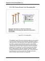
Appendix D Grounding Reference ......................…..................... D-1
1
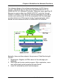
System Overview
Chapter 1 System Overview
1.1 Introduction
Standalone Data Acquisition and Control System
As the growth of PC-based technology, Advantech PC-based
Programmable Controllers have been widely applied in variety of
industrial automation applications. Enhanced from the original
ADAM-5510 controller, the ADAM-5510 Series Controller is a new
series of stand-alone programmable controller features high
memory capacity, user-friendly configuration tool, rich serial
communication interfaces, and also Ethernet port available on
specific models. Applying the ADAM-5510 Series Controller, the C
programmers would be able to handle any complex task easily.
The ADAM-5510 Series Controller includes four models as
following:
-
ADAM-5510M 4-slot PC-based Programmable Controller
ADAM-5510E 8-slot PC-based Programmable Controller
ADAM-5510/TCP 4-slot Ethernet-enabled Programmable
Controller
ADAM-5510E/TCP 8-slot Ethernet-enabled Programmable
Controller
Note: the model number ADAM-5510 is not included in the
ADAM-5510 Series Controller. It’s because all above
ADAM-5510 Series Controller share the same hardware
specifications and software function libraries. However, the
model of ADAM-5510 has it’s own hardware specification
and software library.
1.2 Features
The system of ADAM-5510 Series Controller consists of two major
components: the main unit and I/O modules. The main unit
includes a CPU card, a power regulator, a 4-slot or 8-slot base,
three serial communication ports and one programming port.
Some models also embed one Ethernet port. They has the
following major features:
1-2 ADAM-5510 Series User’s Manual
Chapter 1 System Overview
1.2.1 Control flexibility with C programming
The ADAM-5510 Series Controller is a compact PC in its own
right and includes an 80188 CPU and a built-in ROM-DOS
operating system. It can be used in a way similar to how one uses
an x86 PC in the office. Programmers in C can write and compile
applications in Borland C 3.0 and download to the ADAM-5510
Series Controller. Given the prevalence of C language
programming tools, this is a distinct advantage for many users
and can result in a very short learning curve and very modest
training expense requirements.
1.2.2 RS-232/485 communication ability
The ADAM-5510 Series Controller has four serial communication
ports, giving it excellent communication abilities. This facilitates its
ability to control networked devices. The communication ports of
different models are listed as below table.
COM1
COM2
COM3
COM4
ADAM-5510M ADAM-5510E ADAM-5510/TCP
RS-232
RS-232/485
RS-232
RS-485
RS-485
RS-485
RS-232
RS-232
RS-232
RS-232/485 RS-232/485
RS-232/485
ADAM-5510E/TCP
RS-232/485
RS-485
RS-232
RS-232/485
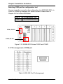
Table 1-1 Communication Ports of ADAM-5510 Series Controller
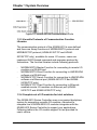
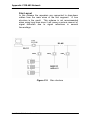
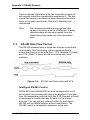
For example, ADAM-5510M COM1 is a dedicated RS-232 port,
COM2 is a dedicated RS-485 port, and COM4 is a RS-232/485
selectable port. These three ports allowed the ADAM-5510M to
satisfy diverse communication and integration demands. COM3 is
a spare programming port for downloading or transferring
executable programs from a host PC. It can also be used as an
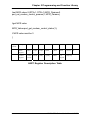
RS-232 communication port. Please refer to following figure and
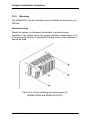
check the location of COM ports.
ADAM-5510 Series User’s Manual 1-3
Chapter 1 System Overview
Figure 1-1 ADAM-5510M Communication Ports
1.2.3 Versatile Protocols of Communication Function
Libraries
The communication protocol of the ADAM-5510 is user-defined
and there are library functions of MODBUS/RTU protocol and
MODBUS/TCP protocol (ADAM-5510/TCP and ADAM5510E/TCP only), available for users. Of course, users can
implement ASCII-based command and response protocol by
themselves. The function libraries include following protocols.
-
-
MODBUS/RTU Master Function for connecting to remote I/O
modules via RS-485 port
MODBUS/RTU Slave Function for connecting to HMI/SCADA
software via RS-485 port
MODBUS/TCP Server Function for connecting to HMI/SCADA
software via Ethernet port (ADAM-5510/TCP and ADAM5510E/TCP only)
MODBUS/TCP Client Function for connecting to Ethernetenabled remote I/O modules via Ethernet port (ADAM5510/TCP and ADAM-5510E/TCP only)
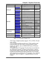
1.2.4 Complete set of I/O modules for total solutions
The ADAM-5510 Series Controller uses a convenient backplane
system for supporting versatile I/O modules. Advantech's
complete line of ADAM-5000 I/O modules integrates with the
ADAM-5510 Series Controller to support your applications.
Following table is the I/O module support list we provided for
user’s choice.
1-4 ADAM-5510 Series User’s Manual
Chapter 1 System Overview
Module
Analog I/O
Digital I/O
Name
Specification
Reference
ADAM-5013
3-ch. RTD input
Isolated
ADAM-5017
8-ch. AI
Isolated
ADAM-5017H
8-ch. High speed AI
Isolated
ADAM-5018
7-ch. Thermocouple input
Isolated
ADAM-5024
4-ch. AO
Isolated
ADAM-5050
7-ch. D I/O
Non-isolated
ADAM-5051
16-ch. DI
Non-isolated
ADAM-5051D
16-ch. DI w/LED
Non-isolated
ADAM-5051S
16-ch. Isolated DI w/LED
Isolated
ADAM-5052
8-ch. DI
Isolated
ADAM-5055S
16-ch. Isolated DI/O w/LED
Isolated
ADAM-5056
16-ch. DO
Non-isolated
ADAM-5056D
16-ch. DO w/LED
Non-isolated
ADAM-5056S
16-ch. Isolated DO w/LED
Isolated
ADAM-5056SO 16-ch. Iso. DO w/LED (source)
Isolated
ADAM-5060
6-ch. Relay output
Isolated
ADAM-5068
8-ch. Relay output
Isolated
ADAM-5069
8-ch. Power Relay output
Isolated
Counter/Frequency ADAM-5080
4-ch. Counter/Frequency
Isolated
Serial I/O
4-port RS232
Non-isolated
Relay Output
ADAM-5090
Table 1-2 I/O Module Support List
-
-
A full range of digital modules support +10 to +30VDC I/O and
relay outputs.
A set of analog modules provide up to 16-bit resolution and
programmable input and output (including bipolar) signal
ranges. For details, refer to ADAM-5000 Series I/O Module
User’s Manual.
A complete set of C language I/O subroutines are included in
the ADAM-5510 Series Controller function library to reduce
programming efforts. Users can easily call these subroutines
to execute the ADAM-5510 Series Controller’s I/O functions
while programming in Borland C 3.0 languages. For a detailed
description, refer to Chapter 5: Programming and Function
Library.
ADAM-5510 Series User’s Manual 1-5
Chapter 1 System Overview
1.2.5 Built-in ROM and RAM disk for programming
The ADAM-5510 Series Controller has built-in Flash Memory and
SRAM for file downloading, system operation and data storage. It
provides 1MB file system, 960 KB free for users to download
programs. There are also 640KB SRAM to provide the memory
needed for efficient application operation and file transfer.
Moreover, users are allowed to decide the battery backup memory
size up to 384KB in the SRAM.
1.2.6 Built-in real-time clock and watchdog timer
The micro-controller also includes a real-time clock and watchdog
timer. The real-time clock records events while they occur. The
watchdog timer is designed to automatically reset the
microprocessor if the system fails. This feature greatly reduces
the level of maintenance required and makes the ADAM-5510
Series Controller ideal for use in applications which required a
high level of system stability.
1.2.7 Built-in Ethernet Port (ADAM-5510/TCP and ADAM5510E/TCP only)
The Ethernet port on ADAM-5510/TCP and ADAM-5510E/TCP
can perform powerful function as following.
-
FTP Server and Client Function
Web Server Function
Send Mail Function
TCP and UDP Connection by Sockets
1-6 ADAM-5510 Series User’s Manual
Chapter 1 System Overview
1.3 ADAM-5510 Series Controllers Specification
1.3.1 System
• CPU: 80188 microprocessor
• Memory:
1.5MB flash memory:
- 256KB system Disk (Drive C: Read Only)
- 256KB flash memory (Accessed by Function LIB)
1024KB file system, 960KB for user applications (Drive
D: Read/Write)
640KB SRAM
- up to 384KB with battery backup (Accessed by
Function LIB)
Operating System: ROM-DOS (MS-DOS 6.22 Compatible)
Real-time Clock: yes
Watchdog Timer: yes
COM1: RS-232 (ADAM-5510M, ADAM-5510/TCP)
RS-232/485 (ADAM-5510E, ADAM-5510E/TCP)
COM2: RS-485
Programming Port/COM3: TX, RX, GND (RS-232 Interface)
COM 4: RS-232/485
I/O Capacity: 4 Slots (ADAM-5510M, ADAM-5510/TCP)
8 Slots (ADAM-5510E, ADAM-5510E/TCP)
-
•
•
•
•
•
•
•
•
1.3.2.1 RS-232 interface (COM1) for ADAM-5510M and ADAM5510/TCP
• Signals: TxD, RxD, RTS, CTS, DTR, DSR, DCD, RI, GND
• Mode: Asynchronous full duplex, point to point
• Connector: DB-9 pin
• Transmission speed: Up to 115.2 Kbps
• Max transmission distance: 50 feet (15.2 m)
1.3.2.2 RS-232/485 interface (COM1) for ADAM-5510E and ADAM5510E/TCP
• RS-232/485 Mode Selectable (Select by jumper setting, refer to
Figure 1-2)
• RS-232 Mode: Asynchronous full duplex, point to point
Signals: TxD, RxD, RTS, CTS, DTR, DSR, DCD, RI, GND
ADAM-5510 Series User’s Manual 1-7
Chapter 1 System Overview
• RS-485 Mode: Half duplex, multi-drop
Signal: DATA+, DATA• Connector: DB-9 pin
• Transmission speed: Up to 115.2 Kbps
• Max transmission distance:
RS-232: 50 feet (15.2 m)
RS-485: 4,000 feet (1220 m)
1.3.3 RS-485 interface (COM2)
• Signals: DATA+, DATA• Mode: Half duplex, multi-drop
• Connector: Screw terminal
• Transmission speed: Up to 115.2 Kbps
• Max transmission distance: 4000 feet (1220 m)
1.3.4 RS-232 programming port (COM3)
• Signals: Tx, Rx, GND
• Mode: Asynchronous, point to point
• Connector: DB-9 pin
• Transmission speed: Up to 115.2 Kbps
• Max transmission distance: 50 feet (15.2 m)
1.3.5 RS-232/485 interface (COM4)
• RS-232/485 Mode Selectable (Select by jumper setting, refer to
Figure 1-2)
• RS-232 Mode: Asynchronous full duplex, point to point
Signals: TxD, RxD, RTS, CTS, DTR, DSR, DCD, RI, GND
• RS-485 Mode: Half duplex, multi-drop
Signals: DATA+, DATA• Connector: DB-9 pin
• Transmission speed: Up to 115.2 Kbps
• Max transmission distance:
RS-232: 50 feet (15.2 m)
RS-485: 4000 feet (1220 m)
1.3.6 Isolation
• Power: 3000 VDC
• Input/Output: 3000 VDC
• Communication: 2500 VDC (COM2 only)
1-8 ADAM-5510 Series User’s Manual
Chapter 1 System Overview
1.3.7 Power
• Unregulated +10 to +30 VDC
• Protected against power reversal
• Power consumption: 2.0 W
1.3.8 Mechanical
• Case: ABS with captive mounting hardware
• Plug-in screw terminal block:
Accepts 0.5 mm2 to 2.5 mm2, 1 - #12 or 2 - #14 to #22 AWG
1.3.9 Environment
• Operating temperature: -10° to 70° C (14° to 158° F)
• Storage temperature: -25° to 85° C (-13° to 185° F)
• Humidity: 5 to 95 %, non-condensing
• Atmosphere: No corrosive gases
Note: Equipment will operate below 30% humidity. However, static
electricity problems occur much more frequently at lower
humidity levels. Make sure you take adequate precautions when
you touch the equipment. Consider using ground straps, antistatic floor coverings, etc. if you use the equipment in low
humidity environments.
1.3.10 Dimensions
The following diagrams show the dimensions of the system unit and
an I/O unit. All dimensions are in millimeters.
Figure 1-2 ADAM-5510M and ADAM-5510/TCP Dimension
ADAM-5510 Series User’s Manual 1-9
Chapter 1 System Overview
Figure 1-3 ADAM-5510E and ADAM-5510E/TCP Dimension
1.3.11 LED Status
ADAM-5510M and ADAM-5510E:
There are four LEDs on the ADAM-5510M and ADAM-5510E front
panel. The LED's indicate ADAM-5510M and ADAM-5510E's
operating status, as explained below:
(1) PWR: power indicator. This LED is on whenever the ADAM-5510M
or ADAM-5510E is powered on.
(2) RUN: program execution indicator. This LED is regularly blinks
whenever the ADAM-5510M or ADAM-5510E is executing a
program.
(3) COMM: communication indicator. This LED blinks whenever the
host PC and the ADAM-5510M or ADAM-5510E is
communicating. Please notice: if the host COM port is
connected to the ADAM-5510M or ADAM-5510E's COM1,
this LED will normally be off. On the other hand, if the host
COM port is connected to the ADAM-5510M and ADAM5510E's COM2, this LED will normally be on.
(4) BATT: battery status indicator. This LED will be on whenever the
SRAM backup battery is low.
ADAM-5510/TCP and ADAM-5510E/TCP:
There are eight LEDs on the ADAM-5510/TCP and ADAM5510E/TCP front panel. The LED's indicate operating status, as
explained below:
1-10 ADAM-5510 Series User’s Manual
Chapter 1 System Overview
(1) PWR: power indicator. This LED is on whenever the ADAM5510/TCP or ADAM-5510E/TCP is powered on.
(2) RUN: program execution indicator. This LED is regularly blinks
whenever the ADAM-5510/TCP or ADAM-5510E/TCP is
executing a program.
(3) COMM: communication indicator. This LED blinks whenever the
host PC and the ADAM-5510/TCP or ADAM-5510E/TCP
is communicating. Please notice: if the host COM port is
connected to the ADAM-5510/TCP or ADAM-5510E/TCP
COM1, this LED will normally be off. On the other hand, if
the host COM port is connected to the ADAM-5510/TCP or
ADAM-5510E/TCP's COM2, this LED will normally be on.
(4) BATT: battery status indicator. This LED will be on whenever the
SRAM backup battery is low.
(5) Speed: This LED is on when the Ethernet communication speed is
100 Mbps.
(6) Link: This LED is normal on whenever the Green indicator. This
LED is on when the ADAM-5510/TCP or ADAM5510E/TCP’s Ethernet wiring is connected.
(7) TX: This LED blinks whenever the ADAM-5510/TCP or ADAM5510E/TCP transmitting data to Ethernet.
(8) RX: This LED blinks whenever the ADAM-5510/TCP or ADAM5510E/TCP receiving data from Ethernet.
ADAM-5510 Series User’s Manual 1-11
2
Installation Guidelines
Chapter 2 Installation Guidelines
This chapter explains how to install an ADAM-5510 Series Controllers.
A quick hookup schemes including both 4-slot and 8-slot models are
provided that let you easily configure your system before
implementing it into your application.
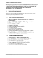
2.1 System Requirements
Before you start installing the ADAM-5510 Series Controller, make
sure the system requirements are met:
2.1.1
Host Computer Requirements
1. IBM PC compatible computer with 486 CPU (Pentium is
recommended).
2. Microsoft 95/98/NT 4.0 (SP3 or SP4) or higher versions.
3. DOS version 3.31 or higher.
3. Borland C 3.0 for DOS
4. At least 32 MB RAM.
5. 20 MB of hard disk space available
6. VGA color monitor.
7. 2x or higher speed CD-ROM.
8. Mouse or other pointing devices.
9. At least one standard RS-232 port (e.g. COM1, COM2).
10. One RS-485 card or RS-232 to RS-485 converter (e. g.
ADAM-4520) for system communication.
2.1.2
ADAM-5510M Requirements
1. One ADAM-5510 Series Controller main unit.
2. One ADAM-5510 Series Controller Startup Manual
3. One core clamp for power supply connection.
4. One ADAM Products Utilities CD.
5. Power supply for ADAM-5510 Series Controller
(+10 to +30 VDC unregulated)
6. One RS-232 straight through DB-9 cable
2-2 ADAM-5510 Series User’s Manual
Chapter 2 Installation Guidelines
2.1.3
I/O Module Requirements
At least one I/O module is needed to use the system. A variety of I/O
modules are available to meet different application requirements.
Table 2-1 gives a current listing of these modules for your reference.
Module
Analog I/O
Digital I/O
Name
Specification
Reference
ADAM-5013
3-ch. RTD input
Isolated
ADAM-5017
8-ch. AI
Isolated
ADAM-5017H 8-ch. High speed AI
Isolated
ADAM-5018
7-ch. Thermocouple input
Isolated
ADAM-5024
4-ch. AO
Isolated
ADAM-5050
7-ch. D I/O
Non-isolated
ADAM-5051
16-ch. DI
Non-isolated
ADAM-5051D 16-ch. DI W/ LED
Relay Output
Non-isolated
ADAM-5052
8-ch. DI
Isolated
ADAM-5056
16-ch. DO
Non-isolated
ADAM-5056D 16-ch. DO W/LED
Non-isolated
ADAM-5060
6-ch. Relay output
Isolated
ADAM-5068
8-ch. Relay output
Isolated
ADAM-5069
8-ch. Power Relay output
Isolated
Counter/FrequencyADAM-5080
4-ch. Counter/Frequency
Isolated
Serial I/O
4-port RS232
Non-isolated
ADAM-5090
Table 2-1 I/O Module Support List
ADAM-5510 Series User’s Manual 2-3
Chapter 2 Installation Guidelines
2.2 Hardware Installation
2.2.1
Selecting I/O Module
To organize an ADAM-5510 Series Controller data acquisition &
control system, you need to select I/O modules to interface the main
unit with field devices or processes that you have previously
determined. There are several things should be considered when you
select the I/O modules.
What type of I/O signal is applied in your system?
How many I/O is required to your system?
How will you place the controller for concentrate the I/O points of
an entire process?
What is the required voltage range for each I/O module?
What isolation environment is required for each I/O module?
What are the noise and distance limitations for each I/O module?
Refer to table 2-2 as I/O module selection guidelines
Choose this type of For these types of field devices
I/O module:
or operations (examples):
Selector switches, pushbuttons,
photoelectric eyes, limit switches,
Discrete input
circuit breakers, proximity
module and block
switches, level switches, motor
I/O module
starter contacts, relay contacts,
thumbwheel switches
Explanation:
Input modules sense ON/OFF
or OPENED/CLOSED signals.
Discrete signals can be either
ac or dc.
Output module signals
Alarms, control relays, fans, lights, interface with ON/OFF or
horns, valves, motor starters,
OPENED/CLOSED devices.
solenoids
Discrete signals can be either
AC or DC.
Thermocouple signals, RTD
signals, temperature transducers, Convert continuous analog
signals into input values for
Analog input module pressure transducers, load cell
transducers, humidity transducers, ADAM-5510M
flow transducers, potentiometers.
Interpret ADAM-5510M output
Analog valves, actuators, chart
Analog output
to analog signals (generally
recorders, electric motor drives,
module
through transducers) for field
analog meters
devices.
Discrete output
module and block
I/O module
Table 2-2 I/O Selection Guidelines
2-4 ADAM-5510 Series User’s Manual
Chapter 2 Installation Guidelines
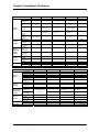
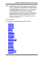
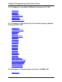
Advantech provides 19 types of ADAM-5000 I/O modules for various
applications so far. The Figure 2-1 and table 2-3 will help you to select
the ADAM-5000 I/O modules quickly and easily.
Figure 2-1 ADAM-5000 I/O Module Selection Chart
ADAM-5510 Series User’s Manual 2-5
Chapter 2 Installation Guidelines
Module
Resolution
Input
Channel
Sampling
Rate
Analog
Input
Analog
Output
Digital
Input and
Digital
Output
Count-er
(32-bit)
COM-M
Isolation
ADAM-5013
16 bit
Voltage
Input
Current
Input
Direct
Sensor
Input
Resolution
Voltage
Output
Current
Output
Digital
Input
Channels
Digital
Output
Channels
Channels
Input
Frequency
Mode
Channels
Type
Analog
Output
Digital Input
and Digital
Output
Count-er
(32-bit)
COM-M
Isolation
ADAM-5017H
12 bit
ADAM-5018
16 bit
ADAM-5024
-
3
8
8
7
-
10
10
8K
10
-
-
±150 mV ±500
mV ±1 V ±5 V
±10 V
±250 mV ±500
mV ±1 V ±5 V
±10 V
±15 mV ±50 mV
±100 mV ±500
mV ±1 V ±2.5 V
-
-
±20 mA*
±20 mA*
-
±20 mA*
Pt or Ni RTD
-
-
J, K, T, E, R, S,
B
-
-
-
-
-
12 bit
-
-
-
-
-
-
-
-
-
-
-
-
-
-
-
-
-
-
-
-
-
-
-
Resolution
Input Channel
Sampling Rate
Voltage Input
Current Input
Direct Sensor
Input
Resolution
Voltage
Output
Current Output
Digital Input
Channels
Digital Output
Channels
Channels
Input
Frequency
Mode
Channels
Type
0~10 V
0~20 mA
4~20 mA
-
-
3000 VDC
Module
Analog
Input
ADAM-5017
16 bit
-
3000 VDC
ADAM-5050
-
3000 VDC
ADAM-5051
-
3000 VDC
ADAM-5051D
-
3000 VDC
ADAM-5051S
-
-
-
-
-
-
-
-
-
-
-
-
-
-
-
-
16 W/LED
16 W/LED
16 DIO (bit-wise
selectabl-e)
-
16
-
-
-
-
-
-
-
-
-
-
-
-
-
2500 VDC
2-6 ADAM-5510 Series User’s Manual
Chapter 2 Installation Guidelines
Module
Analog
Input
Analog
Output
Digital
Input
and
Digital
Output
Count-er
(32-bit)
COM-M
Isolation
Module
Analog
Input
Analog
Output
Digital
Input and
Digital
Output
Count-er
(32bit)
COM-M
Isolation
-
-
-
-
ADAM-5056S
/5056SO
-
-
-
-
-
-
-
-
-
-
-
-
-
-
-
-
-
-
-
-
-
ADAM-5052
Resolution
Input
Channel
Sampling
Rate
Voltage
Input
Current
Input
Direct
Sensor
Input
Resolution
Voltage
Output
Current
Output
Digital
Input
Channels
Digital
Output
Channels
Channels
Input
Frequency
Mode
Channels
Type
Resolution
Input
Channel
Sampling
Rate
Voltage
Input
Current
Input
Direct
Sensor
Input
Resolution
Voltage
Output
Current
Output
Digital
Input
Channels
Digital
Output
Channels
Channels
Input
Frequency
Mode
Channels
Type
ADAM-5055S
ADAM-5056
ADAM-5056D
-
-
-
-
-
-
-
-
-
-
-
-
-
-
-
-
-
-
-
-
-
-
8
8 W/LED
-
-
8 W/LED
16
16 W/LED
-
-
-
-
-
-
-
-
-
-
5000 VRMS
ADAM-5060
-
2500 VDC
ADAM-5068
ADAM-5069
-
ADAM-5080
-
16 W/LED
2500 VDC
ADAM-5090
-
-
-
-
-
-
-
-
-
-
-
-
-
-
-
-
-
-
-
-
-
-
-
-
-
-
-
-
-
-
-
-
-
8 relay (8
form A)
-
-
4
-
6 relay (2 form
A/ 4 form C)
8 relay (8 form
A)
-
-
-
-
-
-
5000 Hz (max)
Frequency,
Up/Down
Counter,
Bi-direction
Counter
1000 VRMS
-
4
RS-232
-
Table 2-3 I/O Selection Guidelines
ADAM-5510 Series User’s Manual 2-7
Chapter 2 Installation Guidelines
2.2.2
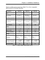
Selecting Power Supply Module
ADAM-5510 Series Controller works under unregulated power source
between +10 and +30 VDC. When you arrange different I/O modules
on ADAM-5510 Series Controller’s backplane, it may require
comparable power supply. Use the following steps as guidelines for
selecting a power supply for your ADAM-5510 Series control system.
Refer to table 2.4 to check the power consumption of ADAM-5510
Series Controller and each I/O module.
Main Units
ADAM-5000/485
ADAM-5000E
ADAM-5000/TCP
ADAM-5510
ADAM-5510M
ADAM-5511
ADAM-5510E
ADAM-5510/TCP
ADAM-5510E/TCP
I/O Modules
ADAM-5013
ADAM-5017
ADAM-5017H
ADAM-5018
ADAM-5024
ADAM-5050
ADAM-5051
ADAM-5051D
ADAM-5056S
ADAM-5056SO
ADAM-5052
ADAM-5055S
ADAM-5056
ADAM-5056D
ADAM-5056S
ADAM-5060
ADAM-5068
ADAM-5069
ADAM-5080
ADAM-5090
Description
Distributed Data Acquisition and Control System based on RS-485
Distributed Data Acquisition and Control System based on RS-485
Distributed Data Acquisition and Control System based on Ethernet
PC-Based Programmable Controller (With Battery Backup)
Enhanced PC-Based Programmable Controller (With Battery Backup)
PC-Based Programmable Controller with Modbus
8-clot PC-Based Programmable Controller
Ethernet-enabled PC-Based Programmable Controller
8-clot Ethernet-enabled PC-Based Programmable Controller
Description
3-Channel RTD Input Module
8-Channel Analog Input Module (mV, mA or High Voltage)
8-Channel High speed Analog Input Module (mV, mA or High Voltage)
7-Channel Thermocouple Input Module (mV, V, mA, Thermocopule)
4-Channel Analog Output Module (V, mA)
16-Channel Universal DIO
16-Channel Digital Input Module
16-Channel Digital Input w/LED Module
16-Channel Isolated Digital Input w/LED Module
16-Channel Digital Input w/LED Module
8-Channel Isolated DI
16-Channel Isolated DIO w/LED Module
16-Channel Digital Output Module
16-Channel Digital Output w/LED Module
16-Channel Isolated Digital Output w/LED Module
6-Channel Relay Output Module ( 2 of Form A, 4 of Form C)
8-Channel Relay Output Module ( 8 of Form A)
8-Channel Power Relay Output Module ( 8 of Form A)
4-Channel Counter/ Frequency Input Module
4-Port RS232 Module
Power Consumption
1.0 W
4.0 W
5.0 W
1.0 W
1.2 W
1.0 W
1.2W
2.0W
2.0W
Power Consumption
1.1 W
1.25 W
2.2 W
0.63 W
2.9 W
1.2 W
0.53 W
0.84 W
0.8 W
0.84 W
0.27W
0.68 W
0.53 W
0.84 W
0.6 W
1.8 W
1.8 W
2.2 W
1.5 W
0.6 W
Table 2.4 Power Consumption of ADAM-5000 series
Calculate the Summary of the whole system’s power consumption.
For example, there are following items in your system.
ADAM-5510M * 3 & ADAM-5024 * 2 & ADAM-5017 * 4 & ADAM-5068
* 2 & ADAM-5080 * 2
The power consumption is:
1.2W * 3 + 2.9W * 2 + 1.25 * 4 + 1.8W * 2 + 1.5W * 2 = 21W
2-8 ADAM-5510 Series User’s Manual
Chapter 2 Installation Guidelines
Select a suitable power supply from Table 2.5 or other comparable
power resource for system operation.
Specification
PWR-242
PWR-243
PWR-244
90~264 VAC
85~132 VAC
170~264VAC
100~240 VAC
Input Frequency
47~63 Hz
47~63 Hz
47~63 Hz
Input Current
1.2 A max.
1.4 A max
25 A/110 VAC
50A/220 VAC
(Inrush current)
Yes
Yes
Yes
Output Voltage
+24VDC
+24VDC
+24VDC
Output Current
2.1 A
3A
4.2 A
Yes
Yes
Yes
Input
Input Voltage
Short Protection
Output
Overload Protection
General
181mm x 113 mm x 181mm x 113 mm x 181mm x 113 mm x
60 mm
60 mm
60 mm
(L x W x H)
(L x W x H)
(L x W x H)
Dimension
o
Operating Temperature
DIN-rail Mountable
o
o
0~50 C
o
(32~122 F)
0~50 C
o
(32~122 F)
0~50 C
o
(32~122 F)
Yes
No
No
Table 2.5 Power Supply Specification Table
ADAM-5510 Series User’s Manual 2-9
Chapter 2 Installation Guidelines
2.2.3
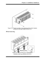
Install Main Unit and Modules
When inserting modules into the system, align the PC board of the
module with the grooves on the top and bottom of the system. Push
the module straight into the system until it is firmly seated in the
backplane connector. Once the module is inserted into the system,
push in the retaining clips (located at the top and bottom of the module)
to firmly secure the module to the system.
Figure 2-2 Module alignment and installation for 4-slot models
(ADAM-5510M and ADAM-5510/TCP)
2-10 ADAM-5510 Series User’s Manual
Chapter 2 Installation Guidelines
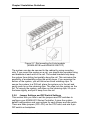
Figure 2-3 Module alignment and installation for 8-slot models
(ADAM-5510E and ADAM-5510E/TCP)
2.2.4
I/O Slots and I/O Channel Numbering
The ADAM-5510M and ADAM-5510E system provides 4 slots for use
with I/O modules. The I/O slots are numbered 0 through 3, and the
channel numbering of any I/O module in any slot starts from 0. For
example, the ADAM-5017 is an 8-channel analog input module. Its
input channel numbering is 0 through 7.
ADAM-5510 Series User’s Manual 2-11
Chapter 2 Installation Guidelines
2.2.5
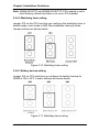
Mounting
The ADAM-5510 Series Controller can be installed on a panel or on a
DIN rail.
Panel mounting
Mount the system on the panel horizontally to provide proper
ventilation. You cannot mount the system vertically, upside down or on
a flat horizontal surface. A standard #7 tatting screw (4 mm diameter)
should be used.
Figure 2-4: Panel mounting screw placement for
(ADAM-5510M and ADAM-5510/TCP)
2-12 ADAM-5510 Series User’s Manual
Chapter 2 Installation Guidelines
Figure 2-5: Panel mounting screw placement for 8-slot models
(ADAM-5510E and ADAM-5510E/TCP)
DIN rail mounting
Retaining Clips
Figure 2-6: Rail mounting for 4-slot models
(ADAM-5510M and ADAM-5510/TCP)
ADAM-5510 Series User’s Manual 2-13
Chapter 2 Installation Guidelines
Figure 2-7: Rail mounting for 8-slot models
(ADAM-5510E and ADAM-5510E/TCP)
The system can also be secured to the cabinet by using mounting
rails. If you mount the system on a rail, you should also consider using
end brackets at each end of the rail. The ended brackets help keep
the system from sliding horizontally along the rail. This minimizes the
possibility of accidentally pulling the wiring loose. If you examine the
bottom of the system, you will notice two small retaining clips. To
secure the system to a DIN rail, place the system on to the rail and
gently push up on the retaining clips. The clips lock the system on the
rail. To remove the system, pull down on the retaining clips, lift up on
the base slightly, and pull it away from the rail.
2.2.6 Jumper Settings and DIP Switch Settings
This section tells you how to set the jumpers and DIP switches to
configure your ADAM-5510 Series Controller. It gives the system
default configuration and your options for each jumper and dip switch.
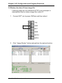
There are three jumpers (JP2~JP4) on the CPU card, and one 8-pin
DIP switch on backplane.
2-14 ADAM-5510 Series User’s Manual
Chapter 2 Installation Guidelines
JP2 is for the watchdog timer setting
JP3 is for COM2 port RS-485 setting (ADAM-5510M and
ADAM-5510E only.)
JP4 is for battery power ON/OFF setting
The following figure shows the location of the jumpers:
Figure 2-8: Jumper locations on the CPU card
2.2.6.1 COM2 port RS-485 control mode setting
The COM2 port is dedicated as an RS-485 interface. In an RS-485
network, handshaking signals such as RTS (Request to Send),
normally control the direction of the data flow. A special I/O circuit in
the ADAM-5510 Series Controller CPU module senses the data flow
direction and automatically switches the transmission direction,
making handshaking signals unnecessary. Jumper JP3 gives users
the option of configuring the COM2 port for automatic control or RTS
control. Jumper settings are shown in Figure 2-5:
Figure 2-9: COM2 port RS-485 control mode setting (JP3)
ADAM-5510 Series User’s Manual 2-15
Chapter 2 Installation Guidelines
Note: ADAM-5510/TCP and ADAM-5510E/TCP CPU module is set to
Auto Mode by default and there is no more JP3 available.
2.2.6.2 Watchdog timer setting
Jumper JP2 on the CPU card lets you configure the watchdog timer to
disable mode, reset mode or NMI (Non-maskable interrupt) mode.
Jumper settings are shown below:
Figure 2-10: Watchdog timer setting
2.2.6.3 Battery backup setting
Jumper JP4 on CPU card lets you configure the battery backup for
SRAM is ON or OFF. Jumper settings are shown below:
Figure 2-11: Watchdog timer setting
2-16 ADAM-5510 Series User’s Manual
Chapter 2 Installation Guidelines
2.2.6.4 RS-232/485 selectable jumper setting
For ADAM-5510M and ADAM-5510/TCP:
The communication mode of COM4 is setting by the Jumper 1 on the
backplane. Please refer to Figure 2-12 to set the communication
interface you prefer to. The default setting of COM4 is RS-485
mode.
Figure 2-12 COM4 RS-232/485 Setting
For ADAM-5510E and ADAM-5510E/TCP:
The Communication mode of COM1 and COM4 are set by JP3 and
JP1 on the backplane. Please refer to Figure 2-13 to set the
communication interface. The default setting of COM1 is RS-232
mode and the default setting of COM4 is RS-485 mode.
ADAM-5510 Series User’s Manual 2-17
Chapter 2 Installation Guidelines
JP4
JP5
JP3
JP1
For COM1
For COM4
Figure 2-13 COM1/COM4 RS-232/485 Setting
2.2.6.5 DIP Switch Setting
DIP Switch
Figure 2-14: ADAM-5510 Series DIP Switch
DIP 1-5
Device ID
Setting
DIP 6
Configuration Tool
via COM1/COM2
DIP 7,8
Reserved
Table 2.6 DIP Switch Function Table
Device ID Setting:
You can set up your device ID by changing DIP Switch 1-5. The
available ID for ADAM-5510 Series Controller is from 1 to 31.
Please refer to the Fig 2.7 Device ID DIP Switch Table to set up your
Device ID.
2-18 ADAM-5510 Series User’s Manual
Chapter 2 Installation Guidelines
DIP 1
On
Off
On
Off
On
Off
On
Off
On
Off
On
Off
On
Off
On
Off
On
Off
On
Off
On
Off
On
Off
On
Off
On
Off
On
Off
On
DIP 2
Off
On
On
Off
Off
On
On
Off
Off
On
On
Off
Off
On
On
Off
Off
On
On
Off
Off
On
On
Off
Off
On
On
Off
Off
On
On
DIP 3
Off
Off
Off
On
On
On
On
Off
Off
Off
Off
On
On
On
On
Off
Off
Off
Off
On
On
On
On
Off
Off
Off
Off
On
On
On
On
DIP 4
Off
Off
Off
Off
Off
Off
Off
On
On
On
On
On
On
On
On
Off
Off
Off
Off
Off
Off
Off
Off
On
On
On
On
On
On
On
On
DIP 5
Off
Off
Off
Off
Off
Off
Off
Off
Off
Off
Off
Off
Off
Off
Off
On
On
On
On
On
On
On
On
On
On
On
On
On
On
On
On
Device ID
1
2
3
4
5
6
7
8
9
10
11
12
13
14
15
16
17
18
19
20
21
22
23
24
25
26
27
28
29
30
31
Table 2.7 Device ID DIP Switch Table
Note: DIP switch 0 is reserved by system configuration. Please leave
this ID available.
ADAM-5510 Series User’s Manual 2-19
Chapter 2 Installation Guidelines
Selecting COM port for configuration tool
You can swap the connection for configuration tool SIMU5KE.EXE via
COM1 or COM2 by changing DIP switch 6 status. Please refer to
Chapter 3.4 for further information.
DIP 6
OFF
ON
Configuration Tool
Via COM2 RS-485
Via COM1 RS-232
COM1, RS-232
COM2, RS-485
Figure 2-15: ADAM-5510 Series COM1 and COM2
2.2.7 Pin assignment of COM port
Table 2.8 RS-232 Port Pin Assignment
2-20 ADAM-5510 Series User’s Manual
Chapter 2 Installation Guidelines
Table 2.9 RS-485 Port Pin Assignment
2.3
System Wiring and Connections
This section provides basic information on wiring the power supply,
I/O units, communication port connection and programming port
connection.
2.3.1
Power supply wiring
Although the ADAM-5510 Series Controller is designed for a standard
industrial unregulated 24 V DC power supply, they accept any power
unit that supplies within the range of +10 to +30 VDC . The power
supply ripple must be limited to 200 mV peak-to-peak, and the
immediate ripple voltage should be maintained between +10 and +30
VDC. Screw terminals +Vs and GND are for power supply wiring.
Note: The wires used should be sized at least 2 mm.
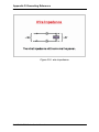
ADAM-5510 Series User’s Manual 2-21
Chapter 2 Installation Guidelines
Power Supply
+10~+30 Vdc
+
-
Figure 2-16: ADAM-5510 Series Controller power wiring
2.3.2
I/O modules wiring
The system uses a plug-in screw terminal block for the interface
between I/O modules and field devices. The following information
must be considered when connecting electrical devices to I/O
modules.
1. The terminal block accepts wires from 0.5 mm 2 to 2.5 mm.
2. Always use a continuous length of wire. Do not combine wires to
make them longer.
3. Use the shortest possible wire length.
4. Use wire trays for routing where possible.
5. Avoid running wires near high energy wiring.
6. Avoid running input wiring in close proximity to output wiring where
possible.
7. Avoid creating sharp bends in the wires.
2.3.3
System Network Connection
The ADAM-5510 Series Controller has four communication ports.
These ports allowed you to program, configure, monitor, and integrate
the remote devices.
Network Connection for System Configuration and Download
The ADAM-5510 Series Controller has a programming port with a
DB-9 connection. This port (COM3) allows you to program, configure,
and troubleshoot the ADAM-5510 Series Controller from your host
computer. The programming port has an RS-232 interface and only
uses TX, RX, and GND signals. The cable connection and the pin
assignment are as follows:
2-22 ADAM-5510 Series User’s Manual
Chapter 2 Installation Guidelines
Figure 2-17 System Configuration Wiring
RS-232 Network Connection for System Monitoring and
Integration
Since the connection for an RS-232 interface is not standardized,
different devices implement the RS-232 connection in different ways.
If you are having problems with a serial device, be sure to check the
pin assignments for the connector. The following table shows the pin
assignments for the ADAM-5510 Series Controller COM1 RS-232
port.
Note: The COM1 of ADAM-5510M and ADAM-5510/TCP is dedicated
as an RS-232 interface. However, the COM1 of ADAM-5510E
and ADAM-5510E/TCP is RS-232/RS-485 selectable. All
models of ADAM-5510 Series Controllers’ COM4 is RS-232/485
selectable.
ADAM-5510 Series User’s Manual 2-23
Chapter 2 Installation Guidelines
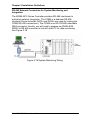
RS-485 Network Connection for System Monitoring and
Integration
The ADAM-5510 Series Controller provides RS-485 interfaces for
multi-drop network integration. The COM2 is a dedicate RS-485
interface (Screw terminals DATA- and DATA+ are used for making the
COM2 RS-485 connections). The COM4 is an RS-232/485 selectable
DB-9 connector. Usually, you will need to prepare an ADAM-4520
RS232 to RS-485 converter to link with host PC for data monitoring
See Figure 2-18.
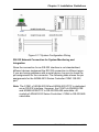
Figure 2-18 System Monitoring Wiring
2-24 ADAM-5510 Series User’s Manual
Chapter 2 Installation Guidelines
Ethernet Network Connection
The ADAM-5510/TCP and ADAM-5510E/TCP provide Ethernet
interface for network integration. Usually, you will need to prepare an
ADAM-6520 Ethernet switch or hub for connecting to other network
devices as following figure.
Figure 2-19 Ethernet Connection
ADAM-5510 Series User’s Manual 2-25
Chapter 2 Installation Guidelines
2.4 Software Installation
When main unit installation is completed, you may begin to configure
the I/O modules and download program to the ADAM-5510 Series
Controller. ADAM-5510 Series Controller comes packaged with a
Utility CD, containing ADAM Product series Utilities as system
configuration tool. While you Insert the CD into the CD drive (e.g. D:)
of the host PC, the Utility software setup menu will start up
automatically. Click the ADAM-5510 Series icon to execute the setup
program, and there will be a Utility executive program installed in your
host PC. See chapter 3 I/O Configuration and Program Download for
the detail operation.
2-26 ADAM-5510 Series User’s Manual
3
I/O Configuration and Program Download
Chapter 3 I/O Configuration and Program Download
This chapter explains how to use the ADAM-5510 Series Utility to
configure the I/O modules and download application programs into the
ADAM-5510 Series system.
Two more utilities will be used to finish the configuration. The first one
is “SIMU5KE.EXE” which needs to be run on ADAM-5510 Series
system for simulating ADAM-5000E system. The other one is “ADAM4000-5000.EXE” which needs to be run on host computer for
configuring the I/O modules.
3.1 System Hardware Configuration
Before the system configuration, you will need to setup the
environment as we mentioned in Chapter 2.1: System Requirements.
3.2 Install Utility Software on Host PC
ADAM-5510 Series systems packaged with a Utility CD, containing
ADAM Product Series Utilities as system configuration tools. While
you insert the CD into the CD drive (e.g. D:) of the host PC, the Utility
software setup menu will start up automatically.
Click the ADAM-5510 Series icon to execute the setup program. After
installation, you will find related directories under “ADAM-5510 Series
Utility” directory as following.
ADAM-5510M-5510E Utility
Config (Configuration tool SIMU5KE.EXE)
Program (ADAM-5510 series utility)
Source (Image, function libraries and examples)
Example (Example programs)
Basic_Function (Basic function examples)
ModbusRTU (Modbus RTU examples)
Image (ADAM-5510M/5510E Drive C image file)
Library (Function Libraries)
5510_Lib (Basic function libraries)
ModRTU_Lib (Modbus RTU libraries)
3-2 ADAM-5510 Series User’s Manual
Chapter 3 I/O Configuration and Program Download
ADAM-5510TCP-5510ETCP Utility
Config (Configuration tool SIMU5KE.EXE)
Program (ADAM-5510 series utility)
Source (Image, function libraries and examples)
*Drive_D (Drive D files for ADAM-5510/TCP and 5510E/TCP only)
*Default_files (Needed by ADAM-5510/TCP and 5510E/TCP only)
*Extension_files (Option files for ADAM-5510/TCP and 5510E/TCP only)
Example (Example programs)
Basic_Function (Basic function examples)
*DemoModbus (Simple examples of Modbus/RTU and Modbus/TCP)
*httpEx (Examples of HTTP server and CGI function)
*Mail (Example of sending mail function)
ModbusRTU (Modbus RTU examples)
*ModbusTCP (Modbus TCP examples)
*TCP (Examples of TCP and UDP connections)
Image (ADAM-5510/TCP and 5510E/TCP Drive C image file)
Lib (Function Libraries)
5510_Lib (Basic function libraries)
*http_Lib (HTTP function libraries)
ModRTU_Lib (Modbus RTU libraries)
*ModTCP_Lib (Modbus TCP libraries)
*Sockets_Lib (Socket libraries)
* For ADAM-5510/TCP and ADAM-5510E/TCP only
ADAM-5510 Series User’s Manual 3-3
Chapter 3 I/O Configuration and Program Download
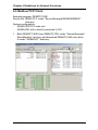
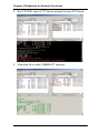
3.3 ADAM-5510 Series Utility Overview
3.3.1 COM port selection for host PC.
3.3.2 “Refresh Folder” button for displaying the files and
directories on drive D: of ADAM-5510 Series system.
3-4 ADAM-5510 Series User’s Manual
Chapter 3 I/O Configuration and Program Download
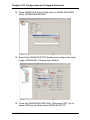
3.3.3 “Config ADAM” button for configuring analog input/output
modules.
3.3.4 “Launch Terminal” button for launching terminal emulation
function.
ADAM-5510 Series User’s Manual 3-5
Chapter 3 I/O Configuration and Program Download
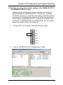
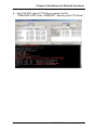
3.3.5 “ADAM-5510/TCP Configuration” button for configuring
network, FTP/HTTP server settings and performing system
initialization function.
3.3.6 “Image Worker” button for backup drive D as image file and
restore image file to drive D.
3-6 ADAM-5510 Series User’s Manual
Chapter 3 I/O Configuration and Program Download
3.3.7 “Download” button for copying files to ADAM-5510 Series
system.
ADAM-5510 Series User’s Manual 3-7
Chapter 3 I/O Configuration and Program Download
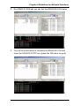
3.4 Example of I/O Module Configuration
3.4.1 Install ADAM-5510 Series Utility
1. Insert the ADAM Products CD and setup ADAM-5510 Series
Utility.
2. After the ADAM-5510 Series Utility has been installed, you will
find two directories under “C:\Program Files\Advantech\ADAM5510 Series Utility” directory. They are named “ADAM-5510M5510E Utility” and “ADAM-5510TCP-5510ETCP Utility”. So if
you are using ADAM-5510M or ADAM-5510E, you have to use
the files under “ADAM-5510M-5510E Utility” directory. If you
are using ADAM-5510/TCP or ADAM-5510E/TCP, you have to
use the files under “ADAM-5510TCP-5510ETCP Utility”
directory.
3-8 ADAM-5510 Series User’s Manual
Chapter 3 I/O Configuration and Program Download
3.4.2 Configure the I/O Modules by ADAM-5510 Series Utility
Following steps will use ADAM-5510/TCP as an example to
demonstrate how to configure the ADAM-5017 Analog Input
Module.
1. Programming Port Wiring for configuration.
PC
straight through cable
RS-232
PC COM port
CD
RX
TX
DTR
GND
DSR
RTS
CTS
RI
1
2
3
4
5
6
7
8
9
COM3 RS-232 (Prog. Port)
straight through cable
ADAM-5510 Series COM3
1
2
3
4
5
6
7
8
9
N/A
TX
RX
N/A
GND
N/A
N/A
N/A
N/A
Analog Input
Analog Output
Digital Input
Digital Output
2. Connect INIT* pin to power GND pin and then reboot.
ADAM-5510 Series User’s Manual 3-9
Chapter 3 I/O Configuration and Program Download
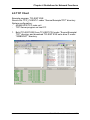
3. Please click “Program” directory under “ADAM-5510TCP5510ETCP Utility” and run “ADAM5510.EXE”, which is so
called ADAM-5510 Series Utility. You will find following figure.
4. Click Refresh button to check if the drive D: of ADAM5510TCP is detected correctly.
3-10 ADAM-5510 Series User’s Manual
Chapter 3 I/O Configuration and Program Download
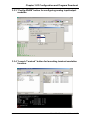
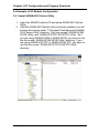
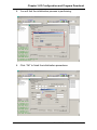
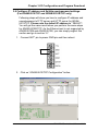
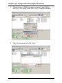
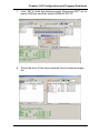
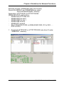
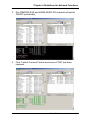
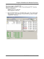
5. Click “Config ADAM” button. Select Slot3 and configure the
input range.
6. Download I/O Module Configuration Tool “SIMU5KE.EXE”
under “Config” directory onto Drive D: of ADAM-5510/TCP.
ADAM-5510 Series User’s Manual 3-11
Chapter 3 I/O Configuration and Program Download
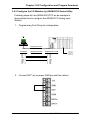
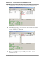
7. Set DIP SW6 as ON.
COM Port Selection for Configuration Tool:
DIP
SW6
ON
COM1/RS-232
8. Set DIP SW1 to SW5 as OFF.
ID Address = 0
DIP
SW1
OFF
0
SW2
0
SW3
0
SW4
0
SW5
0
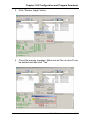
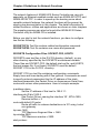
9. Run “SIMU5KE.EXE” and check the Communication Tool does
use COM1/RS-232 port.
3-12 ADAM-5510 Series User’s Manual
Chapter 3 I/O Configuration and Program Download
10. Connect Host PC to COM1/RS-232 on ADAM-5510/TCP by
null modem cable.
PC
COM1 RS-232
Null modem cable
RS-232
PC COM port
CD
RX
TX
DTR
GND
DSR
RTS
CTS
RI
1
2
3
4
5
6
7
8
9
Null modem cable
ADAM-5510 Series COM1
1
2
3
4
5
6
7
8
9
CD
RX
TX
DTR
GND
DSR
RTS
CTS
RI
Analog Input
Analog Output
Digital Input
Digital Output
11. Insert the ADAM Products CD and setup ADAM-4000-5000
Utility.
ADAM-5510 Series User’s Manual 3-13
Chapter 3 I/O Configuration and Program Download
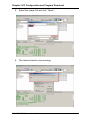
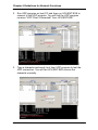
12. Close ADAM-5510 Series Utility and run ADAM-4000-5000
Utility “ADAM40005000.EXE”.
13. Search the ADAM-5510/TCP Module and configure the input
range of ADAM-5017 Analog Input Module.
14. Close the ADAM-4000-5000 Utility. Disconnect INIT* pin to
power GND pin and then reboot ADAM-5510/TCP.
3-14 ADAM-5510 Series User’s Manual
Chapter 3 I/O Configuration and Program Download
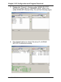
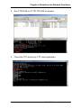
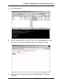
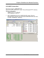
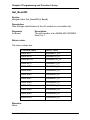
3.5 Initialize the drive D: to default settings. (For ADAM-5510/TCP
and ADAM-5510E/TCP only)
Following steps will show you how to initialize the drive D: to
default settings for ADAM-5510/TCP. The drive D: of ADAM5510/TCP will return to initial files and settings after this function
is performed. You will get the same result when you perform the
same steps for ADAM-5510E/TCP. As there is no system files
on drive D: of ADAM-5510M and ADAM-5510E, you can simply
neglect this section and go to section 3.7.
1. Connect INIT* pin to power GND pin and then reboot.
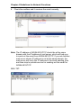
2. Click on “ADAM-5510/TCP Configuration” button.
ADAM-5510 Series User’s Manual 3-15
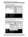
Chapter 3 I/O Configuration and Program Download
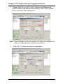
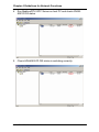
3. Select “HTTPFTP Server” item and click “Go” button.
4.
Click “Yes” to initialize drive D and it will be formatted and all
the files on drive D will be lost. If you would like to keep the
drive contents, please go to section 3.8.
3-16 ADAM-5510 Series User’s Manual
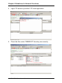
Chapter 3 I/O Configuration and Program Download
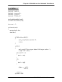
5. You will find the initialization process is performing.
6. Click “OK” to finish the initialization procedures.
ADAM-5510 Series User’s Manual 3-17
Chapter 3 I/O Configuration and Program Download
7. The directory of drive D will be refreshed as following picture.
8. In this demonstration, you will find the FTP & HTTP Server file
is under “WEBROOT” directory.
9. Disconnect INIT* pin to power GND pin and then reboot
ADAM-5510/TCP.
3-18 ADAM-5510 Series User’s Manual
Chapter 3 I/O Configuration and Program Download
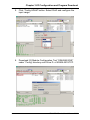
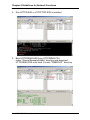
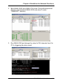
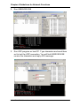
3.6 Configure IP address and ftp/http user/password settings.
(For ADAM-5510/TCP and ADAM-5510E/TCP only)
Following steps will show you how to configure IP address and
users/password of FTP server and HTTP server for ADAM5510/TCP. Please note the default IP address is “10.0.0.1”.
You will get the same result when you perform the same steps
for ADAM-5510E/TCP. As the Ethernet port is not supported by
ADAM-5510M and ADAM-5510E, you can simply neglect this
section and go to section 3.7.
1. Connect INIT* pin to power GND pin and then reboot.
2. Click on “ADAM-5510/TCP Configuration” button.
ADAM-5510 Series User’s Manual 3-19
Chapter 3 I/O Configuration and Program Download
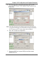
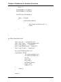
3. Select “Static IP” and fill in the IP address and Gateway IP.
Select “Obtain DNS address automatically” item. Click “Update”
button to perform the configuration.
Note: Above settings is only an example. You have to configure the
network settings by your network environment.
4. Click “OK” to finish the network configuration.
3-20 ADAM-5510 Series User’s Manual
Chapter 3 I/O Configuration and Program Download
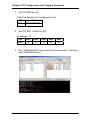
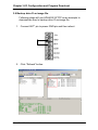
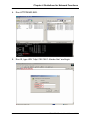
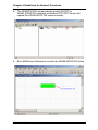
5. Fill in the user name, password and access right for FTP
server and HTTP server. Click “Update” button to perform the
configuration.
Note: This utility can only let you configure one user for FTP server and
one user for HTTP server. If you would like to configure multi-users
for FTP server and HTTP server, please refer to chapter 4.
6. Click “OK” to finish the configuration.
7. Disconnect INIT* pin to power GND pin and then reboot
ADAM-5510/TCP.
ADAM-5510 Series User’s Manual 3-21
Chapter 3 I/O Configuration and Program Download
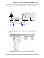
3.7 Download and run the application program automatically after
boot up
Following steps will demonstrate the function by updating
“AUTORUN.BAT” and run “DHCPSTAT.EXE” automatically
after boot up.
1. Download the “DHCPSTAT.EXE” onto ADAM-5510/TCP.
2. Edit “AUTORUN.BAT” under “Source\Drive_D\Default_Files”
directory.
3-22 ADAM-5510 Series User’s Manual
Chapter 3 I/O Configuration and Program Download
3. Update “AUTORUN.BAT” to ADAM-5510/TCP in the utility.
4. Reset the ADAM-5510/TCP and check if the
“DHCPSTAT.EXE” has been executed correctly.
ADAM-5510 Series User’s Manual 3-23
Chapter 3 I/O Configuration and Program Download
3.8 Backup drive D as image file.
Following steps will use ADAM-5510/TCP as an example to
demonstrate how to backup drive D as image file.
1. Connect INIT* pin to power GND pin and then reboot.
2. Click “Refresh” button.
3-24 ADAM-5510 Series User’s Manual
Chapter 3 I/O Configuration and Program Download
3. Click “Image Worker” button and perform the backup function.
4. Click “Backup Image” button.
ADAM-5510 Series User’s Manual 3-25
Chapter 3 I/O Configuration and Program Download
5. Check if there is 10KB free space on drive D and ADAM5510/TCP is in initial mode. Click “Yes” to start the backup.
6. Type the file name and click “Save”.
3-26 ADAM-5510 Series User’s Manual
Chapter 3 I/O Configuration and Program Download
7. Backup function is processing.
8. Click “OK” to finish the backup process. Disconnect INIT* pin
to power GND pin and then reboot ADAM-5510/TCP.
ADAM-5510 Series User’s Manual 3-27
Chapter 3 I/O Configuration and Program Download
3.9 Restore the drive D from image file.
Following steps will use ADAM-5510/TCP as an example to
demonstrate how to restore image file to drive D.
1. Connect INIT* pin to power GND pin and then reboot.
2. Click “Image Worker” button and perform the restore function.
3-28 ADAM-5510 Series User’s Manual
Chapter 3 I/O Configuration and Program Download
3. Click “Restore Image” button.
4. Check the warning message. Make sure all files on drive D can
be deleted and then click “Yes”.
ADAM-5510 Series User’s Manual 3-29
Chapter 3 I/O Configuration and Program Download
5. Select the image file and click “Open”.
6. The restore function is processing.
3-30 ADAM-5510 Series User’s Manual
Chapter 3 I/O Configuration and Program Download
7. Click “OK” to finish the restore process. Disconnect INIT* pin to
power GND pin and then reboot ADAM-5510/TCP.
8. Check the drive D has been restored from the backup image
file.
ADAM-5510 Series User’s Manual 3-31
4
Guidelines for Network Functions
Chapter 4 Guidelines for Network Functions
The network features of ADAM-5510 Series Controller are very rich
especially on Ethernet-enabled models such as ADAM-5510/TCP and
ADAM-5510E/TCP. In order to speed up the learning curve about
versatile network features, the network functions will be present by
step-by-step demonstration in this chapter. The detail information of
related functions, utilities and applications are shown on later chapters.
The sample programs can also be found after ADAM-5510 Series
Controller utility on ADAM CD is installed.
Before you start to test the network functions, you have to configure
two files as following.
SOCKET.CFG: Text file contains related configuration command.
SOCKET.UPW: Text file contains user name and password.
SOCKETS Configuration Files: SOCKET.CFG, HOSTS
SOCKETS uses two files in the D:\CFG directory (default), or any
other directory specified by the SOCKETS environment variable.
These files are SOCKET.CFG, the default start-up file, and HOSTS,
the host names file. If not found, SOCKETS uses the default
SOCKET.CFG in the D:\CFG directory.
SOCKET.CFG is a text file containing configuration commands.
Empty lines and lines starting with # are ignored. Commands are used
to specify protocol parameters like the IP address of the stack,
interface parameters like Packet Driver or Asyncronous Serial lines,
routes and various other parameters. Here is a simple example:
ip address demo
Set the IP address of this host to 192.6.1.1.
interface pdr if0 dix 1500 5
Use Packet Driver, naming the interface ‘if0’, MTU=1500,
Receive buffers = 5
route add default if0 router
Route all traffic to unkown destinations via ‘if0’ using ‘router’
as a gateway
tcp mss 1460
TCP Maximum Segment Size = 1460.
tcp window 2920
TCP Maximum window = 2920.
start prntserv
4-2 ADAM-5510 Series User’s Manual
Chapter 4 Guidelines for Network Functions
Start printer server on PRN using default port of 10.
HOSTS is an optional file containing mappings of IP addresses in
dotted decimal notation to names.
Sample HOSTS file:
192.6.1.1 demo
192.6.1.2 router
192.6.1.3 server
SOCKET.CFG Samples
The following configuration file contains the minimum possible
commands for a valid configuration file: just one. This is to specify that
the interface should use a Packet Driver, the interrupt vector, which
must be searched for. It should use DIX encapsulation, have an MTU
of 1500 and have a maximum of 5 receive buffers. Since no IP
address is specified, BOOTP will be used and the required operating
parameters will be retrieved from a BOOTP server, which must be
available on the network.
SOCKET.CFG:
interface pdr if0 dix 1500 5
The following is a more typical example specifying a static IP address,
a Packet Driver interface, a default route, the TCP MSS and
WINDOW.
SOCKET.CFG:
# Sample configuration file
ip address 192.6.1.1
interface pdr if0 dix 1500 5
route add default if0 192.6.1.2
tcp mss 1460
tcp window 2920
ADAM-5510 Series User’s Manual 4-3
Chapter 4 Guidelines for Network Functions
Format of "SOCKET.UPW"
This is the same file used for the HTTP and FTP server’s (FTPD.EXE)
permissions. This file consists of lines where each line contains a
user's information. A line starting with a # is considered a comment
and is ignored. Each line consists of four fields:
<Username> <Password> <Working Directory> <Permissions> [# comment]
Username: The name of this user. If it is *, it will be used when the
client does not specify a username.
Password: This user's password. If it is *, no password is required
Working Directory: The user will only have access to this directory and
its subdirectories. If it is ‘/’, this user has access to the whole system.
HTTP_DIR can be referred to as ‘\’. If a relative path is specified, it is
appended to HTTP_DIR.
Permissions: IMPORTANT when a user is granted both FTP and
HTTP permissions, the FTP permissions must appear first, otherwise
they will be ignored.
Operations allowed. May contain any combination of the following
tokens:
e - User may 'get' files
p - User may 'post' files
g - User may use cgi
Fields should be separated by single spaces. If any field is missing the
entry is ignored. A comment may follow the last field (permissions) of
the line.
Note: If a default user is supplied, it should always appear first in the
list of users. Only users below the default user will be considered.
Example configuration files, which are used by following
demonstrations:
4-4 ADAM-5510 Series User’s Manual
Chapter 4 Guidelines for Network Functions
SOCKET.CFG:
# Packet driver settings
ip address 192.168.1.4
interface pdr if0 dix 1500 10 0x60
# The following will cause SOCKETS to display IP status
ip address
# The following lines set TCP parameters
ip ttl 64
tcp mss 1460
tcp window 2920
SOCKET.UPW:
su su \WebRoot drwcepgm # su may do everything on whole system.
* * \guest rg
# default user may read (FTP) and get (HTTP)
# from %HTTP_DIR%\guest
test1 test1 \ drep
# test1 can change directories and read files (FTP)
# test1 get and post files (HTTP) in %HTTP_DIR%\
ftp1 ftp1 \WebRoot rd
# ftp1 can read files and change directories (FTP)
# in %HTTP_DIR%\guest and has no HTTP rights
http1 http1 / epgm
# http1 can get and post files, use CGI,
# and use remote console.
# http1 has no FTP rights
user1 user1 \guest\user1 rdcw
# user1 has full FTP access rights to the
# directory %HTTP_DIR%\user\user1
ADAM-5510 Series User’s Manual 4-5
Chapter 4 Guidelines for Network Functions
4.1 FTP Server
Application: FTPD.EXE or HTTPFTPD.EXE
System configuration:
- ADAM-5510/TCP main unit
- FTP Client program on host PC
1. Download FTPD.EXE or HTTPFTPD.EXE onto drive D under
“Webroot” directory.
4-6 ADAM-5510 Series User’s Manual
Chapter 4 Guidelines for Network Functions
2. Run FTPD.EXE or HTTPFTPD.EXE at resident.
3. Check the FTP function by FTP client application.
ADAM-5510 Series User’s Manual 4-7
Chapter 4 Guidelines for Network Functions
4. Login FTP server by another FTP client application.
5. Check the files under “WEBROOT” directory are correctly.
4-8 ADAM-5510 Series User’s Manual
Chapter 4 Guidelines for Network Functions
4.2 HTTP Server
Example program: HTTPDEMO.EXE (without CGI function)
Source file: HTTPDEMO.C under ”Source\Example\httpEx” directory
Application: HTTPD.EXE or HTTPFTPD.EXE
ADAM-5510/TCP configuration:
- ADAM-5510/TCP main unit
- ADAM-5051D at slot 0
- ADAM-5056D at slot 1
- ADAM-5068 at slot 2
- ADAM-5017 at slot 3
- Short ADAM-5051D DI0 to ADAM-5056D DO0, DI1 to DO1,…,
DI15 to DO15
1. Download HTTPD.EXE or HTTPFTPD.EXE onto drive D under
“WEBROOT” directory.
ADAM-5510 Series User’s Manual 4-9
Chapter 4 Guidelines for Network Functions
2. Run HTTPD.EXE or HTTPFTPD.EXE at resident.
3. Build HTTPDEMO.EXE from HTTPDEMO.PRJ
under ”Source\Example\httpEx” directory and download
HTTPDEMO.EXE onto drive D under “WEBROOT” directory.
4-10 ADAM-5510 Series User’s Manual
Chapter 4 Guidelines for Network Functions
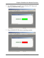
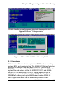
4. Run HTTPDEMO.EXE.
5. Run IE, type URL “http://192.168.1.4/index.htm” and login.
ADAM-5510 Series User’s Manual 4-11
Chapter 4 Guidelines for Network Functions
6. Check the DO channels on ADAM-5056D switching ON/OFF
periodically and check the DI channels’ status is shown on IE.
7. Check the DI channels’ status is switching ON/OFF periodically.
4-12 ADAM-5510 Series User’s Manual
Chapter 4 Guidelines for Network Functions
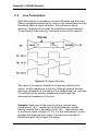
The following figure is the software architecture of HTTP Server
function. The HTTP Server has built-in the ADAM-5510/TCP (or
ADAM-5510E/TCP) Ethernet Controller. Whenever users open the IE
Browser to acquire data from ADAM-5510/TCP controller through
Internet or Intranet, it will call up the existed web pages to provide a
monitor and control portal. All of the commands from the web page
must be linked via a CGI program to the C control program which
handle the real read/write action in ADAM-5000 I/O modules.
Basically, there are three steps in the process of Web Monitoring &
Control.
1. Registration: Register a HTML name for the web page you
designed
2. User login and invoke control program: After registration, users
can invoke local control program by login Server
3. Local I/O activated by local control program
ADAM-5510 Series User’s Manual 4-13
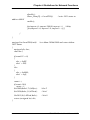
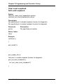
Chapter 4 Guidelines for Network Functions
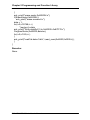
HTTPDEMO.C
#include <stdio.h>
#include <stdlib.h>
#include <string.h>
#include <process.h>
#include "5510drv.h"
#include "CGI_Lib.h"
FILE *fp;
int number = 0;
int count = 1;
unsigned LocalDIO(void);
unsigned int LocalAIO(void);
void ReplaceStr(char *ptr_str1, char *ptr_str2, int len_str);
void main(void)
{
char * homepage_name = "index.htm";
Init501718(3);
if(!Http_Server_Reg(homepage_name)) // registration
return;
adv_printf("Program exiting...");
HttpDeRegister("index.htm");
}
int far Callback(HTTP_PARAMS far* psParams)
// implement your program in this function
{
static char *ptr_XX = 0;
static char *ptr_OO = 0;
char *tmpStr = 0;
static char Htm_Content[] = "HTTP/1.0 200 OK\r\n"
// content of html page, content=1
4-14 ADAM-5510 Series User’s Manual
Chapter 4 Guidelines for Network Functions
"Content-type: text/html\r\n\r\n"
// means refreshes every 1 second
"<html><META HTTP-EQUIV=""Refresh"" content=1>"
"<b>Adam-5051 status is OOOOOOO</b><p>"
"<b>Adam-5017 channel 0 status is XXXXXXX</b>"
"</html>";
number++;
adv_printf("Refresh %d times...\n", number);
if (!ptr_OO)
ptr_OO = strstr(Htm_Content, "OOO");
sprintf(tmpStr, "0x%X", LocalDIO());
ReplaceStr(ptr_OO, tmpStr, 7);
tmpStr = 0;
if (!ptr_XX)
ptr_XX = strstr(Htm_Content, "XXX");
sprintf(tmpStr, "%d", LocalAIO());
ReplaceStr(ptr_XX, tmpStr, 7);
HttpSendData(psParams->iHandle, Htm_Content, strlen(Htm_Content));
return RET_DONE;
}
unsigned LocalDIO(void)
// set Adam-5056&5068 and return Adam-5051 Status
{
unsigned div, dov;
char dov1;
if(count%2==0)
{
dov = 0xffff;
dov1 = 0x0;
}
else
{
dov = 0x0000;
dov1 = 0xff;
}
ADAM-5510 Series User’s Manual 4-15
Chapter 4 Guidelines for Network Functions
count++;
if(count>100)
count = 1;
Set5068(&dov1,2,0,AByte);
Set5056(&dov,1,0,AWord);
//slot 2
//slot 1
Get5051(0,0,AWord,&div);
return ~div;
//slot 0
}
unsigned int LocalAIO(void)
{
//return Adam-5017 channel 0 status
unsigned int aiv;
int ch, tmpcnt;
tmpcnt=0;
while(1)
{
if(AiUpdate(3,0)==0)
{
tmpcnt++;
Get501718(3, 0, &aiv);
if(tmpcnt>=8)
break;
}
}
return aiv;
}
void ReplaceStr(char *ptr_str1, char *ptr_str2, int len_str) // replace string
{
int i;
for(i=0; i<len_str; i++)
ptr_str1[i] = 32;
for(i=0; i<strlen(ptr_str2); i++)
ptr_str1[i] = ptr_str2[i];
}
4-16 ADAM-5510 Series User’s Manual
Chapter 4 Guidelines for Network Functions
Example program: ADAM.EXE (with CGI function)
Source file: ADAM.C and WEBADAM.htm under
“Source\Example\httpEx” directory
Application: HTTPD.EXE or HTTPFTPD.EXE
ADAM-5510/TCP configuration:
- ADAM-5510/TCP main unit
- ADAM-5051D at slot 0
- ADAM-5056D at slot 1
- ADAM-5068 at slot 2
- ADAM-5017 at slot 3
- Short ADAM-5051D DI0 to ADAM-5056D DO0, DI1 to DO1,…,
DI15 to DO15
1. Download HTTPD.EXE or HTTPFTPD.EXE onto drive D under
“WEBROOT” directory.
ADAM-5510 Series User’s Manual 4-17
Chapter 4 Guidelines for Network Functions
2. Run HTTPD.EXE or HTTPFTPD.EXE at resident.
3. Build ADAM.EXE from ADAM.PRJ under ”Source\Example\
httpEx” directory and download ADAM.EXE and WEBADAM.htm
onto drive D under “WEBROOT” directory.
4-18 ADAM-5510 Series User’s Manual
Chapter 4 Guidelines for Network Functions
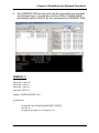
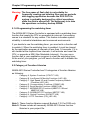
4. Run ADAM.EXE.
5. Run IE, type the URL as “http://192.168.1.4/webadam.htm” and
input the value for DO channels then click “Submit” button.
6. Check the DO channels’ status on ADAM-5056D is changed
correctly.
ADAM-5510 Series User’s Manual 4-19
Chapter 4 Guidelines for Network Functions
ADAM.C
#include <stdio.h>
#include <io.h>
#include <process.h>
#include <stdlib.h>
#include <string.h>
#include "5510drv.h"
#include "CGI_Lib.h"
extern unsigned _stklen = 3000;
extern unsigned _heaplen = 2000;
int far Callback(HTTP_PARAMS far* psParams);
int returnVal(char *ptr_name, char *ptr_end);
void LocalDIO(int DO_val);
int count = 1;
void main(void)
{
char * homepage_name = "Adam.htm";
if(!Http_Server_Reg(homepage_name))
return;
adv_printf("Program exiting\n");
HttpDeRegister("Adam.htm");
}
int far Callback(HTTP_PARAMS far* psParams)
program in this function
{
char buf[200],*p,*ptr_val,*ppass;
int iQueryLen;
char Re_Htm_Content[400];
char *ptr_Re = Re_Htm_Content;
int numberbytes;
int DoVal, DIVal;
4-20 ADAM-5510 Series User’s Manual
//implement your
Chapter 4 Guidelines for Network Functions
*buf = 0;
iQueryLen = _fstrlen(psParams->szQuery);
if (iQueryLen)
_fmemcpy (buf,psParams->szQuery, iQueryLen);
numberbytes = HttpGetData(psParams->iHandle, buf + iQueryLen, 200 iQueryLen);
if (numberbytes < 0)
{
if (numberbytes == (-WOULDBLK))
return RET_OK;
else
adv_printf("wrong input value\n");
}
iQueryLen += numberbytes;
ptr_Re += sprintf(ptr_Re, "HTTP/1.0 200 OK\r\nContent-type:
text/html\r\n\r\n<html><h1>");
if (strncmp(buf,"DOValues=", 9) == 0) {
ptr_val = buf + 9;
if ((p = strchr(ptr_val,'&')) == NULL)
adv_printf("Please click Submit button..\n");
adv_printf("the DO val is 0x%x\n", returnVal(ptr_val, p));
LocalDIO(returnVal(ptr_val, p));
}
ptr_Re += sprintf(ptr_Re, "<P><P><A
HREF=\"/WebAdam.htm\">Back</A>.</html>\n");
HttpSendData(psParams->iHandle, Re_Htm_Content, ptr_Re Re_Htm_Content);
return RET_DONE;
}
int returnVal(char *ptr_name, char *ptr_end)
{
int r_Val, buf_idx;
char buf_val[10];
ADAM-5510 Series User’s Manual 4-21
Chapter 4 Guidelines for Network Functions
memset(buf_val, 0, 10);
for(buf_idx=0; buf_idx<10; buf_idx++)
{
if(ptr_name == ptr_end)
break;
buf_val[buf_idx] = ptr_name[buf_idx];
}
sscanf(buf_val, "%X", &r_Val);
return r_Val;
}
void LocalDIO(int DO_val)
{
unsigned div, dov;
char dov1;
if(count%2==0)
{
dov = ~DO_val;
dov1 = 0x0;
}
else
{
dov = ~DO_val;
dov1 = 0xff;
}
count++;
if(count>100)
count = 1;
Set5068(&dov1,2,0,AByte);
Set5056(&dov,1,0,AWord);
return;
}
4-22 ADAM-5510 Series User’s Manual
Chapter 4 Guidelines for Network Functions
WEBADAM.htm
<html>
<head>
</head>
<body>
<b>
<p><p><p><p>
Please enter Adam-5056 status in hexadecimal format and click Submit.
</b>
<form action="Adam.htm" method=post name="login1">
<table>
<tr>
<td>Adam-5056 Status:</td>
<td align=right><input name="DOValues" type=text size=30
maxlength=50></td>
</tr>
<tr>
<td>
<input name="submit" type=submit value="Submit">
</td>
</tr>
</table>
</body>
</html>
ADAM-5510 Series User’s Manual 4-23
Chapter 4 Guidelines for Network Functions
4.3 Send Mail
Example program: AMAIL.EXE, MAIL.TXT
Source file: ALARMMAIL.C under “Source\Example\mail” directory
Utility: SENDMAIL.EXE, MAKEMAIL.EXE
ADAM-5510/TCP configuration:
- ADAM-5510/TCP main unit
- ADAM-5051D at slot 0
- ADAM-5056D at slot 1
- ADAM-5068 at slot 2
- ADAM-5017 at slot 3
- Short ADAM-5051D DI0 to ADAM-5056D DO0, DI1 to DO1,…,
DI15 to DO15
1. Download SENDMAIL.EXE, MAKEMAIL.EXE and MAIL.TXT onto
drive D under “WEBROOT” directory.
4-24 ADAM-5510 Series User’s Manual
Chapter 4 Guidelines for Network Functions
2. Build AMAIL.EXE from AMAIL.PRJ under ”Source\Example\mail”
directory and download AMAIL.EXE onto drive D under
“WEBROOT” directory.
3. Run AMAIL.EXE and change the value for DO channels from 0 to
FF for triggering the alarm email.
ADAM-5510 Series User’s Manual 4-25
Chapter 4 Guidelines for Network Functions
4. Check the mailbox and it receives the email correctly.
Note: The IP address of ADAM-5510/TCP should be at the same
domain with the IP address of mail server, which will help you
to send out the email from ADAM-5510/TCP. If you ask another
mail server whose IP address is not at the same domain, the
mail server will verify the IP address of the email sending from
and then stop to provide service for sending out the email for
ADAM-5510/TCP.
MAIL.TXT:
4-26 ADAM-5510 Series User’s Manual
Chapter 4 Guidelines for Network Functions
ALARMMAIL.C
#include <stdio.h>
#include <process.h>
#include <errno.h>
#include "5510drv.h"
int SendAlarmMail(void);
int MakeAlarmMail(void);
int count = 1;
void main(void)
{
unsigned div, dov;
char dov1;
if(!MakeAlarmMail())
{
adv_printf("make mail fail..");
return;
}
while(1)
{
adv_printf("Please input Adam-5056 output values: ");
scanf("%X", &dov);
if(count%2==0)
{
dov1 = 0x0;
}
else
{
dov1 = 0xff;
}
if(dov == 0x33)
return;
count++;
if(count>100)
ADAM-5510 Series User’s Manual 4-27
Chapter 4 Guidelines for Network Functions
count = 1;
Set5068(&dov1,2,0,AByte);
Set5056(&dov,1,0,AWord);
Get5051(0,0,AWord,&div);
if(div == 0x00ff)
{
if(!SendAlarmMail())
{
adv_printf("send mail error..");
return;
}
}
}
}
int MakeAlarmMail(void)
{
char * arg_To = "[email protected]";
char * arg_From = "[email protected]";
char * arg_subject = "-s5510TCP";
char * arg_MailContent = "-bmail.txt";
char * arg_O_mail = "-omail.dat";
adv_printf("Making Mail..\n");
if(spawnlp(P_WAIT,
"d:\\mail\\makemail.exe",
"d:\\mail\\makemail.exe",
arg_To,
arg_From,
arg_subject,
arg_MailContent,
arg_O_mail,
NULL)==-1)
{
return 0;
}
return 1;
4-28 ADAM-5510 Series User’s Manual
Chapter 4 Guidelines for Network Functions
}
int SendAlarmMail(void)
{
char * arg1 = "smtp.123.com";
char * arg2 = "mail.dat";
adv_printf("send Alarm mail prepare..\n");
if(spawnlp(P_WAIT,"d:\\mail\\sendmail.exe","d:\\mail\\sendmail.
exe",arg1,arg2,NULL)==-1)
{
return 0;
}
return 1;
}
ADAM-5510 Series User’s Manual 4-29
Chapter 4 Guidelines for Network Functions
4.4 Modbus/TCP Server
Example program: DEMOTS.EXE
Source file: DEMOTS.C under “Source\Example\DEMOMODBUS”
directory
ADAM-5510/TCP configuration:
- ADAM-5510/TCP main unit
- ADAM-5051D at slot 0
- ADAM-5056D at slot 1
- ADAM-5068 at slot 2
- ADAM-5017 at slot 3
- Short ADAM-5051D DI0 to ADAM-5056D DO0, DI1 to DO1,…,
DI15 to DO15
1. Build DEMOTS.EXE from DEMOTS.PRJ under ”Source\Example\
DemoModbus” directory and download DEMOTS.EXE onto drive
D under “WEBROOT” directory.
4-30 ADAM-5510 Series User’s Manual
Chapter 4 Guidelines for Network Functions
2. Run DEMOTS.EXE
3. Run Advantech Modbus/TCP OPC Server and connect to ADAM5051D DI0.
ADAM-5510 Series User’s Manual 4-31
Chapter 4 Guidelines for Network Functions
4. The DEMOTS.EXE will periodically switch ON/OFF to
ADAM_5056D DO channels so Modbus/TCP OPC Server will
update the ADAM-5051D DI0 status correctly.
5. Run ADAMView Software to monitor the ADAM-5051D DI0 status.
4-32 ADAM-5510 Series User’s Manual
Chapter 4 Guidelines for Network Functions
6. The ADAM-5051D DI0 status will be updated correctly in
ADAMView.
DEMOTS.C
#include "mod.h"
#include "5510drv.h"
#define DATASIZE 250
#define sizeofShareMem 4000
int count=0;
unsigned int LocalDIO(void);
int main(void)
{
SOCKET Sock_5510;
int err_code;
unsigned int Share_Mem[sizeofShareMem];
unsigned int tmpcnt=0;
int tmpidx;
ADAM-5510 Series User’s Manual 4-33
Chapter 4 Guidelines for Network Functions
memset(Share_Mem, 0, sizeof(Share_Mem));
if((err_code=ADAMTCP_ModServer_Create(502, 5000, 7,
(unsigned char *)Share_Mem,
sizeof(Share_Mem)))!=0)
//first step
{
adv_printf("error code is %d\n", err_code);
}
Timer_Init();
tmpidx = Timer_Set(1000);
adv_printf("Server started, wait for connect...\n");
while(1)
{
ADAMTCP_ModServer_Update(); //second step: return 0
NO packet, return 1 has packet
if(tmArriveCnt[tmpidx])
{
Timer_Reset(tmpidx);
disable();
Share_Mem[0] = LocalDIO();
status to address 40001
enable();
}
}
//write 5051
ADAMTCP_ModServer_Release();
return 0;
}
unsigned int LocalDIO(void)
5051 Status
{
unsigned div, dov;
char dov1;
//set Adam-5056&5068 and return Adam-
if(count%2==0)
{
dov = 0xffff;
dov1 = 0x0;
4-34 ADAM-5510 Series User’s Manual
Chapter 4 Guidelines for Network Functions
}
else
{
dov = 0x0000;
dov1 = 0xff;
}
count++;
if(count>100)
count = 1;
Set5068(&dov1,2,0,AByte);
Set5056(&dov,1,0,AWord);
Get5051(0,0,AWord,&div);
return (unsigned int)~div;
//slot 2
//slot 1
//slot 0
}
ADAM-5510 Series User’s Manual 4-35
Chapter 4 Guidelines for Network Functions
4.5 Modbus/TCP Client
Example program: DEMOTC.EXE
Source file: DEMOTC.C under “Source\Example\DEMOMODBUS”
directory
System configuration:
- ADAM-5510/TCP main unit
- ADAM-6051 with a switch connected to DI0
1. Build DEMOTC.EXE from DEMOTC.PRJ under ”Source\Example\
DemoModbus” directory and download DEMOTC.EXE onto drive
D under “WEBROOT” directory.
4-36 ADAM-5510 Series User’s Manual
Chapter 4 Guidelines for Network Functions
2. Run DEMOTC.EXE and you can find the ADAM-6051 DI0 status.
3. Turn off the switch which is connected to ADAM-6051 DI0 and
check the ADAM-5510/TCP can update the DI0 status correctly.
ADAM-5510 Series User’s Manual 4-37
Chapter 4 Guidelines for Network Functions
DEMOTC.C
#include "mod.h"
#define Server_Port 502
#define MAXDATASIZE 100
int main(int argc, char *argv[])
{
char * ServerIP;
SOCKET SO_5510;
unsigned char HostData[MAXDATASIZE];
int DataByteCount = 0;
int tmp;
unsigned int tmpcnt=0, tmpcnt1=0;
int errcode;
memset(HostData, MAXDATASIZE, 0);
if(argc==2)
{
ServerIP = argv[1];
}
else
{
adv_printf("Please input Server IP.\n");
return 0;
}
if(ADAMTCP_Connect(&SO_5510, ServerIP, Server_Port)<=0)
{
perror("ADAMTCP_Connect()\n");
ADAMTCP_Disconnect(&SO_5510);
return 0;
}
adv_printf("Starting to send..\n");
while(1)
{
//Query Adam-6051 Server
if((errcode=ADAMTCP_ReadCoilStatus(&SO_5510, 50, 0x01,
0x01, 0x01, &DataByteCount, HostData))<=0)
4-38 ADAM-5510 Series User’s Manual
Chapter 4 Guidelines for Network Functions
{
if(errcode==TCPTimeOut_Err)
perror("Time Out.\n");
else
adv_printf("Error: Error Code is %d\n", errcode);
ADAMTCP_Disconnect(&SO_5510);
return 0;
}
else
{
adv_printf("Adam-6051 Channel 0 Status: ");
for(tmp=0; tmp<DataByteCount; tmp++)
{
adv_printf("%2X", HostData[tmp]&0x01);
}
adv_printf("\n");
}
for(tmpcnt=0; tmpcnt<50000; tmpcnt++) //delay
{for(tmpcnt1=0; tmpcnt1<4; tmpcnt1++){}}
}
return 1;
}
ADAM-5510 Series User’s Manual 4-39
Chapter 4 Guidelines for Network Functions
4.6 Modbus/RTU Slave
Example program: DEMORS.EXE
Source file: DEMORS.C under “Source\Example\DEMOMODBUS”
directory
Utility: Modbus/RTU OPC Server and HMI Software on host PC.
ADAM-5510/TCP configuration:
- ADAM-5510/TCP main unit
- ADAM-5051D at slot 0
- ADAM-5056D at slot 1
- ADAM-5068 at slot 2
- ADAM-5017 at slot 3
- Short ADAM-5051D DI0 to ADAM-5056D DO0, DI1 to DO1,…,
DI15 to DO15
1. Build DEMORS.EXE from DEMORS.PRJ under ”Source\Example\
DemoModbus” directory and download DEMORS.EXE onto drive
D under “WEBROOT” directory.
4-40 ADAM-5510 Series User’s Manual
Chapter 4 Guidelines for Network Functions
2. Run DEMORS.EXE and ADAM-5056D DO channels will switch
ON/OFF periodically.
3. Click “Launch Terminal” button and ensure COM1 has been
released.
ADAM-5510 Series User’s Manual 4-41
Chapter 4 Guidelines for Network Functions
4. Run Modbus/RTU OPC Server on host PC and check ADAM5051D DI0 status.
5. Check ADAM-5051D DI0 status is switching correctly.
4-42 ADAM-5510 Series User’s Manual
Chapter 4 Guidelines for Network Functions
6. Run HMI Software on host PC, link to Modbus OPC Server and
check the ADAM-5051D DI0 status.
7. Check ADAM-5051D DI0 status is switching correctly.
ADAM-5510 Series User’s Manual 4-43
Chapter 4 Guidelines for Network Functions
DEMORS.C
#include <stdio.h>
#include <dos.h>
#include <time.h>
#include <conio.h>
#include "5510drv.h"
#include "RTU.h"
#define MAXDATASIZE 100
#define sizeofShareMem 10
int count;
unsigned int LocalDIO(void);
void main()
{
unsigned int Share_Mem[sizeofShareMem];
char cCh;
char LSR_State;
unsigned int tmpcnt, tmpcnt1;
if(Modbus_COM_Init(COM1, Slave, (unsigned long)9600,
NO_PARITY, DATA8, STOP1)!=0)
{
adv_printf("error\n");
return;
}
adv_printf("init success!!\n");
if(!ADAMRTU_ModServer_Create(3, (unsigned char *)Share_Mem,
sizeof(Share_Mem)))
{
adv_printf("err code is %d\n", Error_Code());
return;
}
adv_printf("server started..\n");
while(1)
{
4-44 ADAM-5510 Series User’s Manual
Chapter 4 Guidelines for Network Functions
disable();
Share_Mem[0] = LocalDIO();
//write 5051 status to
address 40001
enable();
for(tmpcnt=0; tmpcnt<50000; tmpcnt++) //delay
{for(tmpcnt1=0; tmpcnt1<8; tmpcnt1++){}}
}
}
unsigned int LocalDIO(void)
5051 Status
{
unsigned div, dov;
char dov1;
//set Adam-5056&5068 and return Adam-
if(count%2==0)
{
dov = 0xffff;
dov1 = 0x0;
}
else
{
dov = 0x0000;
dov1 = 0xff;
}
count++;
if(count>100)
count = 1;
Set5068(&dov1,2,0,AByte);
Set5056(&dov,1,0,AWord);
Get5051(0,0,AWord,&div);
return (unsigned int)~div;
//slot 2
//slot 1
//slot 0
}
ADAM-5510 Series User’s Manual 4-45
Chapter 4 Guidelines for Network Functions
4.7 Modbus/RTU Master
Example program: DEMORC.EXE
Source file: DEMORC.C under “Source\Example\DEMOMODBUS”
directory
System configuration:
- ADAM-5510/TCP main unit
- ADAM-4056S
1. Build DEMORC.EXE from DEMORC.PRJ under ”Source\Example
\DemoModbus” directory and download DEMORC.EXE onto drive
D under “WEBROOT” directory.
4-46 ADAM-5510 Series User’s Manual
Chapter 4 Guidelines for Network Functions
2. Run DEMORC.EXE and you will find the connection is successful
as following figure. You will also find the LEDs of ADAM-4056S
periodically switch ON/OFF by the command from DEMORC.EXE
DEMORC.C
#include <stdio.h>
#include <dos.h>
#include <time.h>
#include "RTU.h"
#define MAXDATASIZE 100
void main()
{
unsigned char HostData[MAXDATASIZE];
int cnt=0;
unsigned int tmpcnt=0, tmpcnt1=0;
ADAM-5510 Series User’s Manual 4-47
Chapter 4 Guidelines for Network Functions
if(Modbus_COM_Init(COM2, Master, (unsigned long)9600,
NO_PARITY, DATA8, STOP1)!=0)
{
adv_printf("error\n");
return;
}
adv_printf("init success!!\n");
while(1)
{
cnt++;
if(cnt%2==0)
{
HostData[1]=0x0f;
HostData[0]=0xff;
}
else
{
HostData[1]=0x00;
HostData[0]=0x00;
}
if(cnt==10)
cnt = 0;
//Set 4056S status
if(!ADAMRTU_ForceMultiCoils(COM2, 0x01, 0x11, 0x0C,
0x02, HostData))
{
adv_printf("err code is %d\n", Error_Code());
adv_printf("fail send..");
}
else
adv_printf("Success!!\n");
for(tmpcnt=0; tmpcnt<50000; tmpcnt++) //delay
{for(tmpcnt1=0; tmpcnt1<4; tmpcnt1++){}}
}
}
4-48 ADAM-5510 Series User’s Manual
Chapter 4 Guidelines for Network Functions
4.8 TCP Server
Example program: TSERVER.EXE
Source file: TCP_SERVER.C under “Source\Example\TCP” directory
System configuration:
- ADAM-5510/TCP main unit
- TCP Client program on host PC
1. Build TSERVER.EXE from TSERVER.PRJ under ”Source\
Example\TCP” directory and download TSERVER.EXE onto drive
D under “WEBROOT” directory.
ADAM-5510 Series User’s Manual 4-49
Chapter 4 Guidelines for Network Functions
2. Run TSERVER.EXE
3. Run TCP Client program and connect to TSERVER.EXE. The
TSERVER.EXE will response “Hello Word!” to TCP Client
program.
4-50 ADAM-5510 Series User’s Manual
Chapter 4 Guidelines for Network Functions
4. Type characters and send them out from TCP Client program to
test the TCP connection.
TCP_SERVER.C
#include <stdio.h>
#include <stdlib.h>
#ifdef _MSC_VER
#include <malloc.h>
#else
#include <mem.h>
#endif
#include <string.h>
#include <conio.h>
#include <errno.h>
#include "socket.h"
#define Errno errno
#define FALSE 0
#define TRUE 1
#define Host_Port 5510
#define Max_Conn 40
ADAM-5510 Series User’s Manual 4-51
Chapter 4 Guidelines for Network Functions
#define MAXDATASIZE 100
SOCKET remoteSocket[Max_Conn];
int WaitSocketCount[Max_Conn];
int socketTotal = 0;
int timeoutRelease = FALSE;
void ReleaseClient(int idx_so);
int main(void)
{
SOCKET Sock_5510, New_Conn;
struct sockaddr_in Host_addr;
struct sockaddr_in Client_addr;
int sin_size;
int hasConnect, hasMessage;
int maxSocket, sidx, New_Sidx, numbytes, sidx2;
char buf[MAXDATASIZE];
unsigned long pulArgp;
char *str;
int tmpcount=1;
if ((Sock_5510 = socket(AF_INET, SOCK_STREAM, 0)) ==
INVALID_SOCKET)
{
perror("socket");
exit(1);
}
Host_addr.sin_family = AF_INET;
Host_addr.sin_port = htons(Host_Port);
Host_addr.sin_addr.s_addr = INADDR_ANY;
memset(&(Host_addr.sin_zero), 0, 8);
if (bind(Sock_5510, (struct sockaddr *)&Host_addr, sizeof(struct
sockaddr)) == SOCKET_ERROR)
{
perror("bind");
exit(1);
}
4-52 ADAM-5510 Series User’s Manual
Chapter 4 Guidelines for Network Functions
pulArgp = 1;
if(ioctlsocket(Sock_5510, FIONBIO, &pulArgp))
{
perror("ioctlsocket");
exit(1);
}
if (listen(Sock_5510, 5) == SOCKET_ERROR)
{
perror("listen");
exit(1);
}
hasMessage = FALSE;
memset(WaitSocketCount, 0, sizeof(WaitSocketCount));
adv_printf("Server started, wait for connect...\n");
while(1)
{
if (socketTotal > 0)
hasConnect = Host_WaitForClient(Sock_5510, 0);
else
hasConnect = Host_WaitForClient(Sock_5510, 5);
if(hasConnect)
{
adv_printf("Receive client connect request...\n");
sin_size = sizeof(struct sockaddr_in);
if ((New_Conn = accept(Sock_5510, (struct sockaddr *)&Client_addr,
&sin_size)) == INVALID_SOCKET)
{
perror("accept");
continue;
}
if (New_Conn != INVALID_SOCKET)
{
if (socketTotal < Max_Conn)
{
remoteSocket[socketTotal] = New_Conn;
New_Sidx = socketTotal;
ADAM-5510 Series User’s Manual 4-53
Chapter 4 Guidelines for Network Functions
socketTotal++;
}
else
{
if (send(New_Conn, "Connetion full, you are going to be
disconnected!\n", 50, 0) == SOCKET_ERROR)
perror("send");
closesocket(New_Conn);
adv_printf("Connetion full, disconnect client!\n");
}
}
else
adv_printf("(TCP) Invalid incoming socket!\n");
str = "Hello, world!\n";
if (send(remoteSocket[New_Sidx], str, strlen(str), 0) ==
SOCKET_ERROR)
perror("send");
}
if(socketTotal>0)
{
for(sidx=0; sidx<socketTotal; sidx++)
{
hasMessage = Host_WaitForClient(remoteSocket[sidx], 0);
if(hasMessage)
{
if((numbytes=recv(remoteSocket[sidx], buf, sizeof(buf), 0)) ==
SOCKET_ERROR)
{
ReleaseClient(sidx);
}
else
{
if(numbytes>0)
adv_printf("Server receive: %s", buf);
if(tmpcount%2==0)
4-54 ADAM-5510 Series User’s Manual
Chapter 4 Guidelines for Network Functions
str = "ACK\n";
else
str = "A C K\n";
if(numbytes==0)
{
ReleaseClient(sidx);
}
else if(send(remoteSocket[sidx], str, strlen(str), 0) ==
SOCKET_ERROR)
{
ReleaseClient(sidx);
}
memset(buf, 0, sizeof(buf));
tmpcount++;
if(tmpcount>100)
tmpcount = 1;
WaitSocketCount[sidx] = 0;
}
}
else
WaitSocketCount[sidx]++;
if(WaitSocketCount[sidx]>10000)
{
timeoutRelease = TRUE;
ReleaseClient(sidx);
}
}
}
}
return 0;
}
int Host_WaitForClient(int WaitSocket, int i_iWaitMilliSec)
{
ADAM-5510 Series User’s Manual 4-55
Chapter 4 Guidelines for Network Functions
fd_set FdSet;
struct timeval waitTime;
FD_ZERO(&FdSet);
FD_SET(WaitSocket, &FdSet);
waitTime.tv_sec = i_iWaitMilliSec / 1000;
waitTime.tv_usec = (i_iWaitMilliSec % 1000)*1000L;
if (select(0, &FdSet, NULL, NULL, &waitTime) > 0)
return TRUE;
return FALSE;
}
void ReleaseClient(int idx_so)
{
int sidx, sidx2;
sidx = idx_so;
if(timeoutRelease)
{
if (send(remoteSocket[sidx], "Connetion timeout, you are going to be
disconnected!\n", 53, 0) == -1)
perror("send");
}
if(remoteSocket[sidx]!=INVALID_SOCKET)
{
if(closesocket(remoteSocket[sidx])!=0)
adv_printf("Release client resource fail!");
}
for(sidx2 = sidx; sidx2<= socketTotal-1; sidx2++)
{
if(sidx2<socketTotal-1)
{
WaitSocketCount[sidx2] = WaitSocketCount[sidx2+1];
remoteSocket[sidx2] = remoteSocket[sidx2+1];
}
else if(sidx2==socketTotal-1)
{
4-56 ADAM-5510 Series User’s Manual
Chapter 4 Guidelines for Network Functions
WaitSocketCount[sidx2] = 0;
remoteSocket[sidx2] = NULL;
}
}
socketTotal--;
if(timeoutRelease)
adv_printf("Connetion timeout, disconnect client %d!\n", sidx);
else
adv_printf("Socket error, disconnect client %d!\n", sidx);
if(socketTotal==0)
adv_printf("Wait for client connect...\n");
timeoutRelease = FALSE;
}
TCP Client program on host PC
Private Sub Command1_Click()
' Invoke the Connect method to initiate a
' connection.
tcpClient.Connect
End Sub
Private Sub Command2_Click()
End
End Sub
Private Sub Form_Load()
' The name of the Winsock control is tcpClient.
' Note: to specify a remote host, you can use
' either the IP address (ex: "121.111.1.1") or
' the computer's "friendly" name, as shown here.
tcpClient.RemoteHost = "192.168.1.4"
tcpClient.RemotePort = 5510
End Sub
ADAM-5510 Series User’s Manual 4-57
Chapter 4 Guidelines for Network Functions
Private Sub Text1_Change()
tcpClient.SendData Text1.Text
End Sub
Private Sub tcpClient_DataArrival _
(ByVal bytesTotal As Long)
Dim strData As String
tcpClient.GetData strData
Text2.Text = strData
End Sub
4-58 ADAM-5510 Series User’s Manual
Chapter 4 Guidelines for Network Functions
4.9 TCP Client
Example program: TCLIENT.EXE
Source file: TCP_CLIENT.C under “Source\Example\TCP” directory
System configuration:
- ADAM-5510/TCP main unit
- TCP Server program on host PC
1. Build TCLIENT.EXE from TCLIENT.PRJ under ”Source\Example\
TCP” directory and download TCLIENT.EXE onto drive D under
“WEBROOT” directory.
ADAM-5510 Series User’s Manual 4-59
Chapter 4 Guidelines for Network Functions
2. Run TCP Server program on host PC and then run TCLIENT.EXE
to connect to TCP Server program.
3. Type characters and send them out from TCP Server program to
test the TCP connection. You will find TCLIENT.EXE receive the
characters and reply ACK message.
4-60 ADAM-5510 Series User’s Manual
Chapter 4 Guidelines for Network Functions
TCP_CLIENT.C
#include <stdio.h>
#include <stdlib.h>
#ifdef _MSC_VER
#include <malloc.h>
#else
#include <mem.h>
#endif
#include <string.h>
#include <conio.h>
#include <errno.h>
#include "socket.h"
#define Errno errno
#define Server_Port 5510
#define MAXDATASIZE 100
int main(int argc, char *argv[])
{
SOCKET SO_5510;
int numbytes=0;
char buf[MAXDATASIZE];
struct hostent *he;
struct sockaddr_in Server_addr;
char *str1, *str2, *str;
int tmpcount=1;
str1 = "TCP\n";
str2 = "Client\n";
if (argc != 2)
{
fprintf(stderr,"usage: server hostname\n");
exit(1);
}
if ((he=gethostbyname(argv[1])) == NULL)
{
perror("gethostbyname");
exit(1);
}
ADAM-5510 Series User’s Manual 4-61
Chapter 4 Guidelines for Network Functions
if ((SO_5510 = socket(AF_INET, SOCK_STREAM, IPPROTO_TCP)) ==
INVALID_SOCKET)
{
perror("socket");
exit(1);
}
Server_addr.sin_family = AF_INET;
Server_addr.sin_port = htons(Server_Port);
Server_addr.sin_addr = *((struct in_addr *)he->h_addr);
memset(&(Server_addr.sin_zero), 0, 8);
if (connect(SO_5510, (struct sockaddr *)&Server_addr,
sizeof(struct sockaddr)) == SOCKET_ERROR)
{
perror("connect");
exit(1);
}
while(1)
{
if ((numbytes=recv(SO_5510, buf, MAXDATASIZE-1, 0)) ==
SOCKET_ERROR)
{
perror("recv");
exit(1);
}
if(numbytes>0)
{
adv_printf("Received: %s",buf);
memset(buf, 0, sizeof(buf));
if(tmpcount%2==0)
str = str1;
else
str = str2;
sleep(1);
if (send(SO_5510, str, strlen(str), 0) == SOCKET_ERROR)
4-62 ADAM-5510 Series User’s Manual
Chapter 4 Guidelines for Network Functions
{
perror("send");
exit(1);
}
tmpcount++;
if(tmpcount>100)
tmpcount=1;
}
else
{
closesocket(SO_5510);
break;
}
}
return 0;
}
TCP Server program on host PC
Private Sub Command1_Click()
End
End Sub
Private Sub Form_Load()
' Set the LocalPort property to an integer.
' Then invoke the Listen method.
tcpServer.LocalPort = 5510
tcpServer.Listen
Form1.Show ' Show the client form.
End Sub
Private Sub tcpServer_ConnectionRequest _
(ByVal requestID As Long)
' Check if the control's State is closed. If not,
' close the connection before accepting the new
' connection.
If tcpServer.State <> sckClosed Then _
tcpServer.Close
' Accept the request with the requestID
' parameter.
tcpServer.Accept requestID
End Sub
ADAM-5510 Series User’s Manual 4-63
Chapter 4 Guidelines for Network Functions
Private Sub Text1_Change()
' The TextBox control named txtSendData
' contains the data to be sent. Whenever the user
' types into the textbox, the string is sent
' using the SendData method.
tcpServer.SendData Text1.Text
End Sub
Private Sub tcpServer_DataArrival _
(ByVal bytesTotal As Long)
' Declare a variable for the incoming data.
' Invoke the GetData method and set the Text
' property of a TextBox named txtOutput to
' the data.
Dim strData As String
tcpServer.GetData strData
Text2.Text = strData
End Sub
4-64 ADAM-5510 Series User’s Manual
Chapter 4 Guidelines for Network Functions
4.10 UDP Connection
Example program: USERVER.EXE
Source file: UDP_SERVER.C under “Source\Example\TCP” directory
System configuration:
- ADAM-5510/TCP main unit
- UDP program on host PC
1. Build USERVER.EXE from USERVER.PRJ under ”Source\
Example\TCP” directory and download USERVER.EXE onto drive
D under “WEBROOT” directory.
ADAM-5510 Series User’s Manual 4-65
Chapter 4 Guidelines for Network Functions
2. Run USERVER.EXE
3. Run UDP program on host PC. Type characters and send them
out to test the UDP connection. You will find USERVER.EXE
receive the characters and reply ACK message.
4-66 ADAM-5510 Series User’s Manual
Chapter 4 Guidelines for Network Functions
UDP_SERVER.C
#include <stdio.h>
#include <stdlib.h>
#ifdef _MSC_VER
#include <malloc.h>
#else
#include <mem.h>
#endif
#include <string.h>
#include <conio.h>
#include <errno.h>
#include "socket.h"
#define Errno errno
#define FALSE 0
#define TRUE 1
#define Host_Port 5510
#define MAXBUFLEN 100
int main(void)
{
SOCKET Host_Sock;
struct sockaddr_in Host_addr;
struct sockaddr_in Client_addr;
int hasMessage = FALSE;
unsigned long pulArgp;
char buf[MAXBUFLEN];
int addr_len, numbytes;
char* ackmsg = "ACK";
if ((Host_Sock = socket(PF_INET, SOCK_DGRAM, IPPROTO_UDP))
== INVALID_SOCKET)
{
perror("socket");
exit(1);
}
Host_addr.sin_family = AF_INET;
Host_addr.sin_port = htons(Host_Port);
ADAM-5510 Series User’s Manual 4-67
Chapter 4 Guidelines for Network Functions
Host_addr.sin_addr.s_addr = INADDR_ANY;
memset(&(Host_addr.sin_zero), 0, 8);
if (bind(Host_Sock, (struct sockaddr *)&Host_addr, sizeof(struct
sockaddr)) == SOCKET_ERROR)
{
perror("bind");
exit(1);
}
pulArgp = 1;
if(ioctlsocket(Host_Sock, FIONBIO, &pulArgp))
{
perror("ioctlsocket");
exit(1);
}
adv_printf("wait for client send message...\n");
while(1)
{
hasMessage = Host_WaitForMessage(Host_Sock, 0);
if(hasMessage)
{
addr_len = sizeof(struct sockaddr);
if ((numbytes = recvfrom( Host_Sock, buf, sizeof(buf), 0,
(struct sockaddr *)&Client_addr, &addr_len)) ==
SOCKET_ERROR)
{
perror("recvfrom");
if (errno == EWOULDBLOCK)
adv_printf("EWOULDBLOCK");
break;
}
buf[numbytes] = 0;
adv_printf("got packet \"%s\" from %s\n", buf,
inet_ntoa(Client_addr.sin_addr));
4-68 ADAM-5510 Series User’s Manual
Chapter 4 Guidelines for Network Functions
if ((numbytes=sendto(Host_Sock, ackmsg, strlen(ackmsg), 0,
(struct sockaddr *)&Client_addr, sizeof(struct sockaddr))) ==
SOCKET_ERROR)
{
perror("sendto");
break;
}
}
}
closesocket(Host_Sock);
return 0;
}
int Host_WaitForMessage(int serverSocket, int i_iWaitMilliSec)
{
fd_set FdSet;
struct timeval waitTime;
FD_ZERO(&FdSet);
FD_SET(serverSocket, &FdSet);
waitTime.tv_sec = i_iWaitMilliSec / 1000;
waitTime.tv_usec = (i_iWaitMilliSec % 1000)*1000L;
if (select(0, &FdSet, NULL, NULL, &waitTime) > 0)
return TRUE;
return FALSE;
}
UDP program on host PC
Private Sub Command1_Click()
End
End Sub
Private Sub Form_Load()
' The control's name is udpPeerA
With udpPeerA
' IMPORTANT: be sure to change the RemoteHost
' value to the name of your computer.
.RemoteHost = "192.168.1.4"
.RemotePort = 5510 ' Port to connect to.
ADAM-5510 Series User’s Manual 4-69
Chapter 4 Guidelines for Network Functions
.Bind 5510
End With
Form1.Show
End Sub
' Bind to the local port.
' Show the second form.
Private Sub Text1_Change()
' Send text as soon as it's typed.
udpPeerA.SendData Text1.Text
End Sub
Private Sub udpPeerA_DataArrival _
(ByVal bytesTotal As Long)
Dim strData As String
udpPeerA.GetData strData
Text2.Text = strData
End Sub
4-70 ADAM-5510 Series User’s Manual
Chapter 4 Guidelines for Network Functions
Example program: UCLIENT.EXE
Source file: UDP_CLIENT.C under “Source\Example\TCP” directory
System configuration:
- ADAM-5510/TCP main unit
- UDP program on host PC
1. Build UCLIENT.EXE from UCLIENT.PRJ under ”Source\Example\
TCP” directory and download UCLIENT.EXE onto drive D under
“WEBROOT” directory.
ADAM-5510 Series User’s Manual 4-71
Chapter 4 Guidelines for Network Functions
2. Run UDP program on host PC and then run UCLIENT.EXE to
connect to the UDP program. You will find the UDP program
receives “UDP Client Connected!” from UCLIENT.EXE
3. Type a character and send it out from UDP program to test the
UDP connection. You will find UCLIENT.EXE receive the
character correctly.
4-72 ADAM-5510 Series User’s Manual
Chapter 4 Guidelines for Network Functions
UDP_CLIENT.C
#include <stdio.h>
#include <stdlib.h>
#ifdef _MSC_VER
#include <malloc.h>
#else
#include <mem.h>
#endif
#include <string.h>
#include <conio.h>
#include <errno.h>
#include "socket.h"
#define Errno errno
#define BufferSize 100
#define Host_Port 5510
int main(int argc, char *argv[])
{
SOCKET SO_5510;
struct sockaddr_in Server_addr;
struct sockaddr_in From_Addr;
struct hostent *he;
char buf[BufferSize];
int numbytes;
unsigned int From_Size;
char* msg = "UDP Client Conneted!";
if (argc != 2)
{
fprintf(stderr,"usage: uclient xxx.xxx.xxx.xxx\n");
exit(1);
}
if ((he=gethostbyname(argv[1])) == NULL)
{
perror("gethostbyname");
exit(1);
}
ADAM-5510 Series User’s Manual 4-73
Chapter 4 Guidelines for Network Functions
if ((SO_5510 = socket(AF_INET, SOCK_DGRAM, IPPROTO_UDP)) ==
INVALID_SOCKET)
{
perror("socket");
exit(1);
}
Server_addr.sin_family = AF_INET;
Server_addr.sin_port = htons(Host_Port);
Server_addr.sin_addr = *((struct in_addr *)he->h_addr);
memset(&(Server_addr.sin_zero), 0, 8);
if ((numbytes=sendto(SO_5510, msg, strlen(msg), 0,
(struct sockaddr *)&Server_addr, sizeof(struct sockaddr))) ==
SOCKET_ERROR)
{
perror("sendto");
exit(1);
}
adv_printf("sent %d bytes to %s\n", numbytes,
inet_ntoa(Server_addr.sin_addr));
From_Size = sizeof(From_Addr);
if ((numbytes = recvfrom( SO_5510, buf, sizeof(buf), 0,
(struct sockaddr *)&From_Addr, &From_Size)) == -1)
{
perror("recvfrom");
exit(1);
}
buf[numbytes] = 0;
adv_printf("got Ack packet \"%s\" from %s\n", buf,
inet_ntoa(From_Addr.sin_addr));
closesocket(SO_5510);
return 0;
}
4-74 ADAM-5510 Series User’s Manual
Chapter 4 Guidelines for Network Functions
4.11 FTP Client
Utility: FTP.EXE
System configuration:
- ADAM-5510/TCP main unit
1. Download FTP.EXE onto drive D under “WEBROOT” directory.
ADAM-5510 Series User’s Manual 4-75
Chapter 4 Guidelines for Network Functions
2. Run FTP.EXE, login to FTP Server and get file from FTP Server.
3. Check the file is under “WEBROOT” directory.
4-76 ADAM-5510 Series User’s Manual
Chapter 4 Guidelines for Network Functions
4. Run FTP.EXE, login to FTP Server and put the file
“WEBADAM.HTM” under “WEBROOT” directory onto FTP Server.
ADAM-5510 Series User’s Manual 4-77
5
Programming and Function Library
Chapter 5 Programming and Function Library
5.1 Introduction
User-designed ADAM-5510 Series application programs make use of
ADAM-5510 Series library functions. To make the most efficient use of
ADAM-5510 Series’ memory space, the ADAM-5510 Series function
library has been separated into 10 smaller libraries. Therefore, a user
can link only those libraries needed to run his application, and only
those libraries will be included in the compiled executable. The
smaller the linked libraries, the smaller the compiled executable will be.
5.1.1 Programming detail about the ADAM-5510 Series Controller
The operating system of ADAM-5510 Series Controller is ROM-DOS,
which is a MS-DOS equivalent system. It allows users to run
application programs written in assembly language as well as highlevel languages such as C or C++. Certainly, there will be some
limitations when running application programs in the ADAM-5510
Series Controller. In order to build successful applications, please
keep the following limitations and concerns in mind.
5.1.2 Mini BIOS functions
The ADAM-5510 Series Controller provides up to four serial
communication ports including programming port for connecting
peripherals, so the mini BIOS of ADAM-5510 Series Controller only
provides 10 function calls. Since the user’s program cannot use other
BIOS function calls, the ADAM-5510 Series Controller may not work
as intended. Additionally, certain language compilers such as QBASIC
directly call BIOS functions that are not executable in ADAM-5510
Series Controller. The ADAM-5510 Series Controller mini BIOS
function calls are listed in the following table.
5-2 ADAM-5510 Series User’s Manual
Chapter 5 Programming and Function Library
Function
07h
10h
11h
12h
15h
16h
Sub-function
0eh
87h
88h
c0h
0
1
2
18h
19h
1ah
0
1
2
3
4
5
1ch
Task
186 or greater cd-processor esc instruct
TTY Clear output
Get equipment
Get memory size
Extended memory read
Extended memory size
PS/2 or AT style A20 Gate table
Read TTY char
Get TTY status
Get TTY flags
Print "Failed to BOOT ROM-DOS"
message
Reboot system
Get tick count
Set tick count
Get real time clock
Set real time clock
Get data
Set data
Timer tick
Table 5-1: ADAM-5510 Series Controller mini BIOS function calls
5.1.3 Converting program codes
The ADAM-5510 Series Controller has an 80188 CPU. Therefore,
programs downloaded into its flash ROM must be converted into
80186 or 80188 compatible codes firstly, and the floating point
operation must be set to Emulation Mode”. For example, if you
develop the application program in Borland C, you will compile the
program as following picture.
ADAM-5510 Series User’s Manual 5-3
Chapter 5 Programming and Function Library
Figure 5-1: Select “Advanced code generation”
Figure 5-2: Select “Emulation” and “80186” settings
5.1.4 Libraries Sized for Different Memory Modes
The ADAM-5510 Series function libraries support four memory models:
SMALL, MEDIUM, COMPACT and LARGE. You can use library files
sized according to your memory model. For example, if you use small
model you can link UTILITYS.LIB and LIOS.LIB to implement system
and low speed I/O module access functions. On the other hand, if you
use large model, you can link UTILITYL.LIB and LIOL.LIB.
5-4 ADAM-5510 Series User’s Manual
Chapter 5 Programming and Function Library
Figure 5-3: Select “Code generation”
Figure 5-4: Select “Small” Model while using *S.LIB
5.1.5 Limitations
Certain critical files are always kept in flash ROM, such as operating
system, BIOS, and monitoring files. The ADAM-5510 Series Controller
provides an additional 1MB flash disk as drive D. There is up to
960KB free space for user’s application program. As some additional
system files and network utilities for ADAM-5510/TCP and ADAM5510E/TCP are distributed on drive D, the free space for user’s
application program should be less than 960KB. Besides, there are
256KB flash memory and up to 384KB battery backup SRAM for
user’s applications which can be accessed by function library.
ADAM-5510 Series User’s Manual 5-5
Chapter 5 Programming and Function Library
Warning: The free space of flash disk is not suitable for
frequently creating and deleting files such as periodic
data logging application because the DOS FAT file
system is probably destroyed by critical operations
while the disk is almost full. The better way is to take
the operations on battery backup SRAM.
5.1.6 Programming the watchdog timer
The ADAM-5510 Series Controller is equipped with a watchdog timer
function that resets the CPU or generates an interrupt if processing
comes to a standstill for any reason. This feature increases system
reliability in industrial standalone and unmanned environments.
If you decide to use the watchdog timer, you must write a function call
to enable it. When the watchdog timer is enabled, it must be cleared
by the application program at intervals of less than 1.6 seconds. If it is
not cleared at the required time intervals, it will activate and reset the
CPU, or generate a NMI (Non-Maskable Interrupt). You can use a
function call in your application program to clear the watchdog timer.
At the end of your program, you still need a function call to disable the
watchdog timer.
5.2 Category of Function Libraries
ADAM-5510 Series Controller has 10 categories of function libraries
as following:
-
Category A. System Functions (UTILITY*.LIB)
Category B. Low Speed AI Module Functions (LAI*.LIB)
Category C. High Speed I/O and Counter/Frequency Module
Functions (HIO*.LIB)
Category D. Communication Functions (COMM*.LIB)
Category E. Serial Module Functions (A5090*.LIB)
Category F. MODBUS/RTU Functions (MBRTU*.LIB and
MBRTU9*.LIB)
Category G. MODBUS/TCP Functions (MBTCP*.LIB)
Category H. Socket Functions (SOCKET*.LIB)
Category I. HTTP Functions (CGI_LIB*.LIB)
Note 1: These function libraries support Borland C 3.0 for DOS only.
Note 2: Please include all necessary ADAM-5510 Series function
libraries in your project file.
5-6 ADAM-5510 Series User’s Manual
Chapter 5 Programming and Function Library
Note 3: The ADAM-5510 Series function libraries, which come with
ADAM CD version 2.20 or later, support 8 slot and 4 slot main
units, i.e., ADAM-5510E, ADAM-5510E/TCP, ADAM-5510M
and ADAM-5510/TCP simultaneously. So if you have already
used ADAM-5510M and would like to use 8 slot main unit
such as ADAM-5510E in your system, it is strongly
recommended that you build your projects for both ADAM5510M and ADAM-5510E by linking latest function libraries on
ADAM CD version 2.20 or later. Just keep one version of
function libraries for all ADAM-5510 Series Controllers will
simplify the maintenance.
5.3 Library Index
5.3.1 Category A. System Functions: (UTILITY*.LIB)
ADAMdelay
Get_BoardID
Get_NodeID
GetRTCtime
SetRTCtime
LED_init
LED_OFF
LED_ON
ProgramByte
ProgramSector
EraseSector
Get_SysMem
Set_SysMem
read_mem
Get_NVRAM_Size
Set_NVRAM_Size
Timer_Init
Timer_Reset
Timer_Set
Release_All
tmArriveCnt
WDT_clear
WDT_disable
WDT_enable
write_backup_ram
read_backup_ram
adv_printf()
ADAM-5510 Series User’s Manual 5-7
Chapter 5 Programming and Function Library
5.3.2 Category B. Low Speed AI Module Functions (LAI*.LIB)
AiUpdate()
Init5013()
Get5013()
GetRange5013()
Init501718()
Get501718()
GetRange501718()
5.3.3 Category C. High Speed I/O and Counter/Frequency Module
Functions (HIO*.LIB)
Init5017H()
GetRange5017H()
Get5017H()
Init5024()
Set5024()
GetRange5024()
Get5050()
Get5051()
Get5052()
Get5055()
Set5050()
Set5055()
Set5056()
Set5060()
Set5068()
Set5069()
InitDIFilter()
Init5080()
Get5080()
Clear_Counter()
Start_Stop_Counter()
ReadOverflowFlag()
SetInitCounterVal()
GetRange5080()
SetRange5080()
5.3.4 Category D. Communication Functions: (COMM*.LIB)
checksum()
5-8 ADAM-5510 Series User’s Manual
Chapter 5 Programming and Function Library
RS-485 Port (COM2) Functions
com_485_install()
com_485_deinstall()
com_485_set_format()
com_485_set_speed()
com_485_flush_rx()
com_485_flush_tx()
com_485_rx()
com_485_rx_empty()
com_485_tx()
com_485_tx_string()
com_485_tx_empty()
Program Port (COM3) Functions
com_pgm_install()
com_pgm_deinstall()
com_pgm_flush_rx()
com_pgm_flush_tx()
com_pgm_rx()
com_pgm_rx_empty()
com_pgm_set_format()
com_pgm_set_speed()
com_pgm_tx()
com_pgm_tx_empty()
com_pgm_tx_string()
RS-232/485 Port (COM1) Functions
Note: For ADAM-5510M and ADAM-5510/TCP, COM1 supports RS-232 only.
The following library functions support RS-485 automatic data flow control.
So it is not necessary for users to take care of the control of data flow
direction.
com_install()
com_deinstall()
com_set_format()
com_set_parity()
com_set_speed()
com_rx()
com_tx()
com_rx_empty(), com_tx_empty()
com_tx_ready()
com_tx_string()
com_flush_rx(), com_flush_tx()
ADAM-5510 Series User’s Manual 5-9
Chapter 5 Programming and Function Library
com_carrier()
com_clear_break(), com_set_break()
com_clear_local_loopback(),com_set_local_loopback()
com_disable_fifo(), com_enable_fifo()
com_get_line_status(), com_set_line_params(),
com_lower_dtr(), com_raise_dtr()
com_lower_rts(), com_raise_rts()
com_read_scratch_register(), com_write_scratch_register()
CRC16()
com_get_modem_status()
modem_autoanswer()
modem_command_state()
modem_command()
modem_dial()
modem_handup()
modem_initial()
RS-232/485 Port (COM4) Functions
com_232_485_install()
com_232_485_deinstall()
com_232_485_set_format()
com_232_485_set_speed()
com_232_485_flush_rx()
com_232_485_flush_tx()
com_232_485_rx()
com_232_485_rx_empty()
com_232_485_tx()
com_232_485_tx_string()
com_232_485_tx_empty()
5.3.5 Category E. Serial Module Functions (A5090*.LIB)
For ADAM-5090 Serial COM Ports:
port_install()
port_deinstalled()
port_select()
reset_slot()
port_reset()
which_has_been_installed()
port_set_speed()
port_set_format()
port_disable_fifo()
port_enable_fifo()
5-10 ADAM-5510 Series User’s Manual
Chapter 5 Programming and Function Library
port_carrier()
port_clear_break()
port_set_break()
port_clear_local_loopback()
port _set_local_loopback()
port_get_line_status()
port_set_line_params()
port_get_modem_status()
port_get_modem_control_status()
port_set_modem_control_params()
port_lower_dtr()
port_raise_dtr()
port_raise_rts()
port_lower_rts()
modem_initial_90()
modem_command_90()
modem_command_state_90()
modem_autoanswer_90()
modem_dial_90()
modem_handup_90()
port_flush_rx()
port_flush_tx()
port_rx_error()
port_rx_ready()
char port_rx()
port_tx_empty()
port_tx()
port_tx_string()
5.3.6 Category F. MODBUS/RTU Functions (MBRTU*.LIB and
MBRTU9*.LIB)
For ADAM-5510 Series COM Ports:
Modbus_COM_Init()
Modbus_COM_Release()
Error_Code()
ADAMRTU_ForceMultiCoils()
ADAMRTU_ForceSingleCoil()
ADAMRTU_PresetMultiRegs()
ADAMRTU_PresetSingleReg()
ADAMRTU_ReadCoilStatus()
ADAMRTU_ReadHoldingRegs()
ADAM-5510 Series User’s Manual 5-11
Chapter 5 Programming and Function Library
ADAMRTU_ReadInputRegs()
ADAMRTU_ReadInputStatus()
ADAMRTU_ModServer_Create()
Ver_RTU_Mod()
For ADAM-5090 Serial COM Ports:
Error_Code()
Modbus_5090_Init()
Modbus_5090_Release()
A5090_RTU_ForceMultiCoils()
A5090_RTU_ForceSingleCoil()
A5090_RTU_PresetMultiRegs()
A5090_RTU_PresetSingleReg()
A5090_RTU_ReadCoilStatus()
A5090_RTU_ReadHoldingRegs()
A5090_RTU_ReadInputRegs()
A5090_RTU_ReadInputStatus()
5.3.7 Category G. MODBUS/TCP Functions (MBTCP*.LIB)
Ver_TCP_Mod()
Modbus TCP Client Functions:
ReturnErr_code()
ADAMTCP_Connect()
ADAMTCP_Disconnect()
ADAMTCP_ForceMultiCoils()
ADAMTCP_ForceSingleCoil()
ADAMTCP_PresetMultiRegs()
ADAMTCP_PresetSingleReg()
ADAMTCP_ReadCoilStatus()
ADAMTCP_ReadHoldingRegs()
ADAMTCP_ReadInputRegs()
ADAMTCP_ReadInputStatus()
Modbus TCP Server Functions:
ADAMTCP_ModServer_Create()
ADAMTCP_ModServer_Update()
ADAMTCP_ModServer_Release()
5-12 ADAM-5510 Series User’s Manual
Chapter 5 Programming and Function Library
5.3.8 Category H. Socket Functions (SOCKET*.LIB)
Socket function:
accept ()
bind ()
closesocket ()
connect ()
ioctlsocket ()
getpeername ()
getsockname ()
getsockopt ()
htonl ()
htons ()
inet_addr ()
inet_ntoa ()
listen ()
ntohl ()
ntohs ()
recv ()
recvfrom ()
select ()
send ()
sendto ()
setsockopt ()
shutdown ()
socket ()
Database function:
gethostbyaddr()
gethostbyname()
gethostname ()
getservbyport()
getservbyname()
getprotobynumber()
getprotobyname()
ADAM-5510 Series User’s Manual 5-13
Chapter 5 Programming and Function Library
5.3.9 Category I. HTTP Functions (CGI_LIB*.LIB)
Socket function:
HttpRegister()
HttpDeRegister()
HttpGetData()
HttpSendData()
HttpSubmitFile()
HttpGetStatus()
HttpGetVersion()
GetStackPointer()
GetStackSegment()
SetStackPointer()
SetStackSegment()
5-14 ADAM-5510 Series User’s Manual
Chapter 5 Programming and Function Library
5.4 Function Library Description
5.4.1 System Functions (UTILITY*.LIB)
ADAMdelay
Syntax:
void ADAMdelay(unsigned short msec)
Description:
Delays program operation by a specified number of milliseconds.
Parameter
msec
Description
From 0 to 65535.
Return value:
None.
Example:
#include "5510drv.h"
void main(void)
{
/* codes placed here by user */
ADAMdelay(1000); /* delay 1 sec. */
/* codes placed here by user */
}
Remarks:
ADAMDelay will possibly decrease the performance so it is
recommended to use for loop instead.
ADAM-5510 Series User’s Manual 5-15
Chapter 5 Programming and Function Library
Get_BoardID
Syntax:
unsigned char Get_BoardID(int Board)
Description:
Gets the type identification of the I/O module in a controller slot.
Parameter
Int Board
Description
The slot number of an ADAM-5510 SERIES,
from 0 to 7.
Return value:
The return values are:
I/O Module name
ADAM-5017
ADAM-5018
ADAM-5017H
Return Value
ADAM5017_ID
ADAM5018_ID
ADAM5017H_ID
ADAM-5013
ADAM5013_ID
ADAM-5080
ADAM5080_ID
ADAM-5052
ADAM5052_ID
ADAM-5050
ADAM5050_ID
ADAM-5051
ADAM5051_ID
ADAM-5056
ADAM5056_ID
ADAM-5060
ADAM5060_ID
ADAM-5068
ADAM5068_ID
ADAM-5069
ADAM5069_ID
ADAM-5024
ADAM5024_ID
Remarks:
None
5-16 ADAM-5510 Series User’s Manual
Chapter 5 Programming and Function Library
Get_NodeID
Syntax:
unsigned char Get_NodeID(void)
Description:
Gets the DIP switches number of the ADAM-5510 SERIES Controller.
Parameter
None.
Description
Return value:
The DIP switches number of the ADAM-5510 SERIES Controller.
Example:
#include "5510drv.h"
unsigned char SystemNodeNumber;
unsigned char IOModuleName, SlotNumber;
void main(void)
{
SystemNodeNumber = Get_NodeID();
if( SystemNodeNumber == 0x15)
{
/* Read IO module name in Slot 0*/
SlotNumber = 0;
IOModuleName = Get_BoardID(SlotNumber);
if( IOModuleName == ADAM5051_ID)
{
/* IO Board is current, put your code in Here*/
}
else
{
adv_printf("\nThe IO Board is NOT ADAM5051");
adv_printf("\nPlease Check your system setup");
}
}
else
adv_printf("\nNode number Error!");
}
Remarks :
None
ADAM-5510 Series User’s Manual 5-17
Chapter 5 Programming and Function Library
GetRTCtime
SetRTCtime
Syntax:
unsigned char GetRTCtime(unsigned char Time)
void SetRTCtime(unsigned char Time,unsigned char data)
Description:
GetRTCtime: Reads Real-Time Clock chip timer. A user can activate
a program on the date desired.
SetRTCtime: Sets date and time of the real-time clock.
Parameter
Time
Description
RTC_sec
RTC_min
RTC_hour
RTC_day
RTC_week
RTC_month
RTC_year
data
the second
the minute
the hour
the day
day of the week
the month
the year
New contents.
Return value:
The value requested by the user.
Example:
#include "5510drv.h"
void main(void)
{unsigned char sec=0,min=0,hour=12;
adv_printf("Time %02d:%02d:%02d\n",GetRTCtime(RTC_hour),
GetRTCtime(RTC_min), GetRTCtime(RTC_sec));
adv_printf("Set current time 12:00:00\n");
SetRTCtime(RTC_sec,sec);
SetRTCtime(RTC_min,min);
SetRTCtime(RTC_hour,hour);
adv_printf("Time %02d:%02d:%02d\n",GetRTCtime(RTC_hour),
GetRTCtime(RTC_min), GetRTCtime(RTC_sec));
}
Remarks:
None.
5-18 ADAM-5510 Series User’s Manual
Chapter 5 Programming and Function Library
LED_init
LED_OFF
LED_ON
Syntax:
void LED_init(void)
void LED_OFF(int which_led)
void LED_ON(int which_led)
Description:
Turns LED lights on and off. The LED I/O port must be initialized first.
It will take a little time for the light to stabilize following the signal for
the turning on and turning off of the light.
Parameter
which_led
Description
PWR
RUN
COMM
Return value:
None.
Example:
#include "5510drv.h"
void main(void)
{
LED_init();
/* flash COMM led */
while(1)
{
LED_ON(COMM);
ADAMdelay(500);
LED_OFF(COMM);
}
}
Remarks:
None.
ADAM-5510 Series User’s Manual 5-19
Chapter 5 Programming and Function Library
ProgramByte
ProgramSector
EraseSector
Syntax:
BOOL EraseSector( unsigned long ulBase )
BOOL ProgramByte( unsigned long ulAddress, BYTE byte )
BOOL ProgramSector( unsigned long ulAddress_s, unsigned char far
* SECTOR_DATA)
Description:
EraseSector : Erases a 64 KB sector of data in the 256 KB Flash
memory
ProgramByte : Programs a byte of information into the 256 KB Flash
memory.
This feature supports data-logging or mass
information storage.
ProgramSector : Programs an entire 32 KB sector of data of the global
variable, SECTOR_DATA[], into 256 KB Flash
memory.
Parameter
ulBase
Description
User-determined address range to be erased,
taken from addresses in the range 0x80000L to
0xB0000L.
ulAddress
User–determined destination address for byte
transfer, taken from the range 0x80000L to
0xBFFFFL.
ulAddress_s
User-determined destination address in the Flash
memory, taken from addresses in the range
0x80000L to 0xB8000L.
SECTOR_DATA Pointer at the starting address in the origin memory
of the user's data array.
Return value:
TRUE Successful transfer to Flash memory.
FALSE Error (destination already occupied, excess address range, or
program error).
5-20 ADAM-5510 Series User’s Manual
Chapter 5 Programming and Function Library
read_mem
Syntax:
unsigned char read_mem (int memory_segment , unsigned int i)
Description:
Reads far memory data, 256 KB Flash memory, from 0x80000L to
0xBFFFFL, where (the Absolute Address) = (SEG*16 + OFFSET). For
example, (0x800FFL) = (0x8000*16 + 0x00FF).
Parameter
memory_segment
i
Description
User-determined address taken from the range
0x8000 to 0xBF00.
Offset for use in location of memory taken from
the range 0x0000 to 0x0FFF.
Return value:
The value in memory storage at the indicated address.
Example:
#include "5510drv.h"
void main(void)
{
unsigned char sector[32768];
unsigned char data;
unsigned long addr,sector_num;
unsigned int i;
adv_printf("erase sector 0x80000L\n");
if(EraseSector(0x80000L))
adv_printf("erase succeed \n");
adv_printf("Write data(55) to 0x80000~0x80001\n");
data=55;
ProgramByte(0x80000L,data);
ProgramByte(0x80000L+1,data);
ProgramByte(0x80000L+2,data);
for(i=0;i<3;i++)
{
adv_printf("read%d data=%d\n",i,read_mem(0x8000,0x0000+i));
ADAM-5510 Series User’s Manual 5-21
Chapter 5 Programming and Function Library
}
adv_printf("erase sector 0x80000L\n");
if(EraseSector(0x80000L))
adv_printf("erase succeed \n");
data = 1;
for(i=0;i<32768;i++)
*(sector+i)=data;
adv_printf("Write data(0x01) to 0x80000~0x87FFF\n");
ProgramSector(0x80000,§or);
for(i=0;i<100;i++)
{
adv_printf("read%d data=%d\n",i,read_mem(0x8000,0x0000+i));
}
}
Remarks:
None.
5-22 ADAM-5510 Series User’s Manual
Chapter 5 Programming and Function Library
Get_SysMem
Set_SysMem
Syntax:
unsigned char Get_SysMem(unsigned char which_byte)
void Set_SysMem(unsigned char which_byte, unsigned char data)
Description:
Get_SysMem: Reads a byte from security SRAM.
Set_SysMem: Writes a byte to security SRAM. Security SRAM
supports 113 bytes for user storage of important
information.
Parameter Description
which_byte
From 0 to 112, user-determined.
data
Value to be saved.
Return value:
The value in a byte of security SRAM.
Example:
#include "5510drv.h"
void main(void)
{
unsigned char data[4] = {1,2,3,4};
int i;
/* save current value */
for(i=10;i < 14;i++)
{
Set_SysMem(i, data[i-10]);
adv_printf("data=%d\n",Get_SysMem(i));
}
}
Remarks:
None
ADAM-5510 Series User’s Manual 5-23
Chapter 5 Programming and Function Library
Get_NVRAM_Size
Set_NVRAM_Size
Syntax:
unsigned char Get_NVRAM_Size(void)
void Set_NVRAM_Size(unsigned char sector)
Description:
Gets the size of battery backup RAM.
Sets the size of battery backup RAM.
(The unit is sectors, each sector is 4KB in size. Maximum size is 384
KB theoretically.)
Parameter Description
sector NVRAM size in 4 KB sectors, from 1 to 96 sectors.
Return value:
Get_NVRAM_Size: sector Number of sectors NVRAM size is set to,
from 1 to 96.
Example:
#include "5510drv.h"
void main()
{
unsigned char sector;
sector = Get_NVRAM_Size();
adv_printf(“Backup ram=%dKbyte\n”,sector*4);
/*Set Bacup ram 40Kbyte*/
Set_NVRAM_Size(10);
}
Remarks:
None.
5-24 ADAM-5510 Series User’s Manual
Chapter 5 Programming and Function Library
write_backup_ram
read_backup_ram
Syntax:
void write_backup_ram(unsigned long index, BYTE data)
unsigned char read_backup_ram(unsigned long index)
Description:
Writes a byte to battery backup memory.
Reads the value in backup RAM at index address, maximum 384 KB
total backup RAM, index = 0 – 393214;
Parameter
index
in total.
data
Description
An index for data in the battery backup RAM, from
0 to 393214; maximum 384 KB battery backup SRAM
A byte of data that the programmer wants to write to
battery-protected SRAM.
Return value:
The single-byte value in backup RAM at address index.
Example:
#include "5510drv.h"
void main()
{
unsigned long addr;
unsigned char data;
/*write the data 0x55 into battery backup memory, index=10*/
data=0x55;
write_backup_ram(10,data);
adv_printf("data=%x\n",read_backup_ram(10));
}
Remarks:
None
ADAM-5510 Series User’s Manual 5-25
Chapter 5 Programming and Function Library
Timer_Init()
Syntax:
int Timer_Init()
Description:
Initializes the timer built into the 80188 microprocessor. The return
value “0” means the initialization of the time was successful. The
return value “1” means the timer had already been initialized.
Parameter Description
None.
Return value:
0: Initialization was successful.
1: The timer had already been initialized.
Remarks:
None.
5-26 ADAM-5510 Series User’s Manual
Chapter 5 Programming and Function Library
Timer_Reset
Syntax:
void Timer_Reset(int idx)
Description:
Resets the timer identified by the integer idx to its initial state.
Parameter Description
idx Timer index.
Return value:
None.
Remarks:
None.
ADAM-5510 Series User’s Manual 5-27
Chapter 5 Programming and Function Library
Timer_Set
Syntax:
int Timer_Set(unsigned int msec)
Description:
Requests a timer function from the microprocessor and then sets the
time interval of the function. Timer intervals are set in 5 millisecond
increments. The function return value is an integer representing the ID
of the timer function when it is successful.
A return value “-1” means the request failed. Programmers should
consider whether an assigned timer has timed-out when programming
for timer functions. The value of the variable tmArriveCnt[idx] can be
checked to verify timer status.
A value of 0 indicates that the timer is still counting. Values other than
0 mean the timer has timed-out.
Parameter Description
msec
Time interval set, max. value is 65536.
Return value:
Integer Function success, value represents function timer ID. Max.
value of 100.
-1 Function failure.
Remarks:
Timer function calls in the ADAM-5510 SERIES are emulated as timer
functions in a PLC. Applications using timer functions will run less
efficiently the more timer functions are running simultaneously in a
program. Please refer to Example 9 on the utility diskettes for details.
5-28 ADAM-5510 Series User’s Manual
Chapter 5 Programming and Function Library
Release_All
Syntax:
void Release_All()
Description:
Releases all timer resources of the ADAM-5510 SERIES system.
Parameter
None.
Description
Return value:
None.
Remarks:
None.
Example:
#include "5510drv.h"
void main()
{
int idx;
/* Initializes the timer built into the 80188 microprocessor */
Timer_Init();
/* Sets time interval of the timer to 1 second.
*/
idx=Timer_Set(1000);
/* Checks whether the timer has timed out
*/
while(tmArriveCnt[idx]==0)
{
/* user can attend to other tasks...
*/
adv_printf("test");
}
/* Resets the current timer to its initial state.
Timer_Reset(idx);
/* Releases all timer resources
*/
Release_All();
*/
}
ADAM-5510 Series User’s Manual 5-29
Chapter 5 Programming and Function Library
WDT_clear,WDT_disable,WDT_enable
Syntax:
void WDT_clear(void)
void WDT_disable(void)
void WDT_enable(void)
Description:
Clear watchdog timer.
Disable watchdog timer.
Enable watchdog timer.
When the watchdog timer is enabled, it will have to be cleared at least
once every 1.5 seconds. The watchdog timer default value is “disable”.
Parameter Description
None.
Return value:
None.
Example:
#include "5510drv.h"
void main(void)
{
int i;
WDT_enable();
for(i=0;i<100;i++)
{
/*put your code in Here*/
WDT_clear();
/*put your code in Here*/
}
WDT_disable();
}
Remarks:
None
5-30 ADAM-5510 Series User’s Manual
Chapter 5 Programming and Function Library
adv_printf
Syntax:
void adv_printf(char *pFormat, ...);
Description:
Print string to console. This function has the same usage as printf()
function. However, it has lower priority to be executed.
Parameter Description
The same as printf() of standard Borland C 3.0 library function.
Return value:
None.
Example:
for(i=0;i<4;i++)
{
type[i]=Get_BoardID(i);
if( type[i] > 0x18)
type[i]=0;
}
for(i=0;i<4;i++)
{
adv_printf("IO slot %d is %s \n",i+1,s_type[type[i]]);
}
adv_printf("press any key to continue...\n");
getch();
Remarks:
If printf() function is put within while loop such as Modbus/RTU server
function, it will decrease the performance of server function due to
higher priority of printf(). So it is strongly recommended that uses
adv_printf() instead, which has lower priority than printf().
ADAM-5510 Series User’s Manual 5-31
Chapter 5 Programming and Function Library
5.4.2 Low Speed AI Module Functions (LAI*.LIB)
AiUpdate
Syntax:
int AiUpdate(int Board, int *channel)
Description:
Checks whether the data of a low-speed analog input module, such as
ADAM-5017, ADAM-5018 and ADAM-5013, is ready to be accessed.
Parameter Description
int Board
The slot number of an ADAM-5510 Series, from 0 to 7.
int *channel The return value indicates the channel for which data is
ready.
Valid value 0 to 7 for ADAM-5017.
Valid value 0 to 6 for ADAM-5018.
Valid value 0 to 2 for ADAM-5013.
Return value:
int status; 0 : Ready
-1 : Not ready
-2 : The hardware of the module failed
Example:
Please refer to the ADAM-5017/5018 Example
Remarks:
None.
5-32 ADAM-5510 Series User’s Manual
Chapter 5 Programming and Function Library
Get5013
Syntax:
void Get5013(int Board, int Channel, void *pValue)
Description:
Reads the data value in an ADAM-5013 module.
Parameter Description
Board
0 – 7 for Slot0 ...Slot7.
Channel
0 – 2 for ADAM-5013.
*pValue
The value returned.
Note: The *pValue for ADAM-5013 must be interpreted in reference to
the input range that was set during module configuration.
Return Value:
None.
Example:
Please refer to the ADAM-5013 Example
Remarks:
None.
ADAM-5510 Series User’s Manual 5-33
Chapter 5 Programming and Function Library
Get501718
Syntax:
void Get501718(int Board, int Channel, void *pValue)
Description:
Reads the data value in an I/O module.
Parameter Description
Board
0 – 7 for Slot0 ...Slot7.
Channel
0 - 6 for ADAM-5018; 0 - 7 for ADAM-5017
*pValue
The value returned.
Note: The *pValue for ADAM-5017 and ADAM-5018 must be
interpreted in reference to the range input that was set during module
configuration.
Return value:
None.
Example:
Please refer to the ADAM-5017/5018 Example
Remarks:
None.
5-34 ADAM-5510 Series User’s Manual
Chapter 5 Programming and Function Library
GetRange5013
Syntax:
void GetRange5013(int Board, int Channel, void *pRange)
Description:
Reads the input range in an ADAM-5013 module.
Parameter Description
Board
0 – 7 for Slot0 ...Slot7.
Channel
0 – 2 for ADAM-5013.
*pRange
The input range code returned. (See Appendix B.)
Return Value:
None.
Example:
Please refer to the ADAM-5013 Example
Remarks:
None.
ADAM-5510 Series User’s Manual 5-35
Chapter 5 Programming and Function Library
GetRange501718
Syntax:
void GetRange501718(int Board, int Channel, void *pRange)
Description:
Reads the input range in an ADAM-501718 module.
Parameter Description
Board
0 – 7 for Slot0 ...Slot7.
Channel
0 – 7 for ADAM-5017, 0-6 for ADAM-5018.
*pRange
The input range code returned (See Appendix B.)
Return Value:
*pRange
The input range code returned.
Example:
Please refer to the ADAM-5017/5018 Example
Remarks:
None.
5-36 ADAM-5510 Series User’s Manual
Chapter 5 Programming and Function Library
Init5013
Syntax:
void Init5013(int Slot)
Description:
Initializes ADAM-5013. Note that ADAM-5013 must be initialized
before other commands are issued to it.
Parameter
Slot
Description
From 0 to 7.
Return Value:
None.
Example:
Please refer to the ADAM-5013 Example
Remarks:
None.
ADAM-5510 Series User’s Manual 5-37
Chapter 5 Programming and Function Library
Init501718
Syntax:
void Init501718(int Slot)
Description:
Initializes ADAM-5017 or ADAM-5018. Note that ADAM-5017 or
ADAM-5018 must be initialized prior to other commands being issued
to them.
Parameter
Slot
Description
From 0 to 7.
Return value:
None.
Example:
Please refer to the ADAM-5017/5018 Example
Remarks:
None.
5-38 ADAM-5510 Series User’s Manual
Chapter 5 Programming and Function Library
ADAM-5013 Example
#include "5510drv.h"
void main()
{
char ch;
unsigned char Range;
int *pRange,*pVaule;
int i,j;
int channel,slot;
/*Initial ADAM-5013)*/
/*One ADAM-5013 module on slot 2*/
slot=2;
Init5013(slot);
GetRange5013(slot,0,pRange);
Range=*pRange & 0xff;
adv_printf("range is 0x%x \n",Range);
for(i=0;i<100;)
{
while(AiUpdate(slot, &channel)==0)
{
Get5013(slot,channel,pVaule);
adv_printf("\n channel= %d ADAM-5013=%04d
\n",channel,*pVaule);
i++;
}
}
Release_All();
}
ADAM-5510 Series User’s Manual 5-39
Chapter 5 Programming and Function Library
ADAM-5017/5018 Example
#include "5510drv.h"
void main()
{
unsigned char Range,Format;
int *pRange,*pVaule;
int i;
int channel,slot;
char *RangeArray[6]={"+/-10V","+/-5V","+/-1V","+/-500mv","+/150mV","+/-20mv"};
/*Initial ADAM-5017(ADAM-5018)*/
/*One ADAM-5017 module on slot 0*/
slot=0;
Init501718(slot);
GetRange501718(slot,0,pRange);
Range=*pRange & 0xff;
Format=(*pRange & 0xff00)>>8;
adv_printf("with range is %s format is 0x%x\n",RangeArray[Range8],Format);
for(i=0;i<100;)
{
while(AiUpdate(slot, &channel)==0)
{
Get501718(slot,channel,pVaule);
adv_printf("\n channel= %d ADAM-5017=%04d
mV\n",channel,*pVaule);
i++;
}
}
}
5-40 ADAM-5510 Series User’s Manual
Chapter 5 Programming and Function Library
5.4.3 High Speed I/O and Counter/Frequency Module Functions
(HIO*.LIB)
Get5017H
Syntax:
void Get5017H(int Board, int Channel, void *pValue)
Description:
Reads the data value in an ADAM-5017H module.
Parameter Description
Board
0 – 7 for Slot0 ...Slot7.
Channel
0 – 7 for ADAM-5017H.
*pValue
The value returned.
Note: The pValue for ADAM-5017H must be interpreted in reference
to the input range that be setup in the module configuration
Return Value:
None.
Example:
Please refer to the ADAM-5017H Example
Remarks:
None.
ADAM-5510 Series User’s Manual 5-41
Chapter 5 Programming and Function Library
GetRange5017H
Syntax:
void GetRange5017H(int Board, int Channel, void *pRange)
Description:
Reads the input range in an ADAM-5017H module.
Parameter Description
Board
0 – 7 for Slot0 ...Slot7.
Chanel
0 – 7 for ADAM-5017H.
*pRange
The input range code returned. (See Appendix B.)
Return Value:
None.
Example:
Please refer to the ADAM-5017H Example
Remarks:
None.
5-42 ADAM-5510 Series User’s Manual
Chapter 5 Programming and Function Library
Init5017H
Syntax:
void Init5017(int Slot)
Description:
Initializes ADAM-5017H. Note that ADAM-5017H must be initialized
before other commands are issued to it.
Parameter Description
Slot
From 0 to 7.
Return Value:
None.
Example:
Please refer to the ADAM-5017H Example
Remarks:
None.
ADAM-5510 Series User’s Manual 5-43
Chapter 5 Programming and Function Library
ADAM-5017H Example
#include "5510drv.h"
void main()
{
int channel,*pRange;
int Format,Range;
int slot;
int *pValue[8];
char *RangeArray[12]={"+/-10V","0~10V","+/-5V","0~5V",
"+/-2.5v","0-2.5V","+/-1V","0-1V",
"+/-500mV","0~500mV","4~20mA","0~20mA"};
slot=1;
Init5017H(slot);
channel=0;
GetRange5017H(slot,channel,pRange);
Format=(*pRange & 0xff00)>>8;
Range=*pRange & 0xff;
adv_printf("\n(with range is %s format is
0x%x)",RangeArray[Range],Format);
Init5017H(slot);
for(channel=0;channel<8;channel++)
{
Get5017H(slot,channel,pValue+channel);
adv_printf("\n adam5017h channel:%d =
%d",channel,*(pValue+channel));
}
}
5-44 ADAM-5510 Series User’s Manual
Chapter 5 Programming and Function Library
Init5024
Syntax:
void Init5024(int Slot, int ch0_val, int ch1_val, int ch2_val, int ch3_val)
Description:
Initializes ADAM-5024 module in the slot indicated, loading userspecified analog output values into each of the modules' four channels.
Parameter
ch0_val
ch1_val
ch2_val
ch3_val
Description
The initial value output by channel 0.
The initial value output by channel 1.
The initial value output by channel 2.
The initial value output by channel 3.
Return Value:
None.
Example:
Please refer to the ADAM-5024 Example
Remarks:
None.
ADAM-5510 Series User’s Manual 5-45
Chapter 5 Programming and Function Library
Set5024
Syntax:
void Set5024(void *pValue, int Board, int Channel)
Description:
Specifies the output of a channel of a selected ADAM-5024.
Parameter Description
*pValue
The value set for analog output.
Board
Slot number = 0 - 7.
Channel
AO channel = 0 - 3.
Return Value:
None.
Example:
Please refer to the ADAM-5024 Example
Remarks:
None.
5-46 ADAM-5510 Series User’s Manual
Chapter 5 Programming and Function Library
ADAM-5024 Example
#include "5510drv.h"
void main()
{
unsigned long *pValue;
int channel,slot;
slot=3;
/*initializes outputs of all channels
of the ADAM-5024 in slot 3 to output a
value of 0 */
Init5024(slot,0,0,0,0);
/*Value set 2000mV*/
*pValue=2000;
for(channel=0;channel<4;channel++)
{
Set5024(pValue,slot,channel);
adv_printf("\n channel %d = %d mV",channel,*pValue);
}
}
ADAM-5510 Series User’s Manual 5-47
Chapter 5 Programming and Function Library
Get5050, Get5051, Get5052, Get5055
Syntax:
void Get5050(int Board, int Bit, int Size, void *pValue)
void Get5051(int Board, int Bit, int Size, void *pValue)
void Get5052(int Board, int Bit, int Size, void *pValue)
void Get5055(int Board, int Bit, int Size, void *pValue)
Description:
Reads the data value in an I/O module.
Parameter Description
Board
ADAM-5510 Series slot number, from 0 to 7.
Bit
See “Size” parameter below.
Size
ABit, AByte, AWord
If Size= ABit, Bit=0..15 (pin0..pin15)
If Size=AByte, Bit=0 for Low Byte data; Bit=8 for High
Byte data
If Size=AWord, Bit does not care. Always word data.
pValue
The value returned.
Return value:
None.
Example:
void main(void)
{
unsigned char Bdata;
unsigned int Wdata;
/* Slot0, pin13, data=0 or 1 */
Get5051(0, 13, ABit, &Bdata);
/* Slot2, pin0~pin7, Bdata=Low Byte data */
Get5051(2, 0, AByte, &Bdata);
/* Slot3, pin0~pin15, Wdata=Word data */
Get5051(3, 0, AWord, &Wdata);
Remarks:
Digital filter function is available. Please refer to InitDIFilter() function.
5-48 ADAM-5510 Series User’s Manual
Chapter 5 Programming and Function Library
Set5050, Set5055, Set5056, Set5060, Set5068, Set5069
Syntax:
void Set5050(void *pValue, int Board, int Bit, int Size)
void Set5055(void *pValue, int Board, int Bit, int Size)
void Set5056(void *pValue, int Board, int Bit, int Size)
void Set5060(void *pValue, int Board, int Bit, int Size)
void Set5068(void *pValue, int Board, int Bit, int Size)
void Set5069(void *pValue, int Board, int Bit, int Size)
Description:
Sets the digital output for ADAM-5050, ADAM-5055, ADAM-5056,
ADAM-5060, ADAM-5068 and ADAM-5069 modules to the specified
values.
Parameter
pValue
Board
Bit
Size
Description
The digital value specified by the user to be output.
0 to 7 (Slot0 .. Slot7).
See "Size" parameter below.
ABit, AByte, AWord
If Size = ABit, Bit = 0 ...15 (pin0 ... pin15)
If Size = AByte, Bit = 0 is Low Byte data
Bit = 8 is High Byte data
If Size = AWord, Bit does not care, always word
data.
Return Value:
None.
Example:
void main(void)
{
unsigned char Bitdata = 1;
Set5056( &Bitdata, 0, 13, ABit);
/ * Output 1 to slot 0, pin 13 */
}
Remarks:
None
ADAM-5510 Series User’s Manual 5-49
Chapter 5 Programming and Function Library
InitDIFilter
Syntax:
void InitDIFilter(int iSlot, int iCh, unsigned int MIN_Lo_Width, unsigned
int MIN_High_Width);
Description:
Set time interval of digital filter for DI channel.
Parameter
iSlot
iCh
MIN_Lo_Width
MIN_High_Width
Description
Slot no. from 0 to 7
Channel no. 0 –15 depends on DI module
Time interval of DI filter for Low state
(5 ~ 65535 msec)
Time interval of DI filter for High state
(5 ~ 65535 msec)
Return Value:
None.
Example:
#include <stdio.h>
#include <stdlib.h>
#include <string.h>
#include "5510DRV.H"
#define MaxSlot 8
char *s_type[0x1f]={
"",
"",
"",
"",
"ADAM5017 ", /*0x4*/
"ADAM5018 ",
"",
"",
"",
"ADAM5013 ", /*0x9*/
"",
"",
"ADAM5017H", /*0xc*/
"ADAM5018H",
"",
"ADAM5052 ",
5-50 ADAM-5510 Series User’s Manual
Chapter 5 Programming and Function Library
"ADAM5050 ",
"ADAM5051 ",
"ADAM5056 ",
"",
"ADAM5060 ",
"ADAM5055",
"",
"",
"ADAM5024 "
"",
"",
"",
"",
"",
"ADAM5080 ",
};
/*0x10*/
/*0x14*/
/*0x18*/
/*0x1e*/
void main()
{
unsigned char type[MaxSlot];
unsigned DI_Value, DO_Value;
unsigned Pre_DI_Value;
unsigned Pre_DI_Value1;
unsigned DI_Value1;
unsigned Pre_DI_Value2;
unsigned DI_Value2;
char c;
int i;
int Slot5051, Slot5056, Slot5052, Slot5050, Slot5055;
int inputdelay;
for(i=0;i<MaxSlot;i++)
{
type[i]=Get_BoardID(i);
type[i] &= 0x1f;
if( type[i] > 0x18)
type[i]=0;
}
for(i=0;i<MaxSlot;i++)
//print module slot positions
{
adv_printf("IO slot %d is %s \n",i,s_type[type[i]]);
}
adv_printf("press any key to continue...\n");getch();
for(i=0; i<MaxSlot; i++)
ADAM-5510 Series User’s Manual 5-51
Chapter 5 Programming and Function Library
{
if(type[i]==0x11)
Slot5051 = i;
//5051 Slot position
if(type[i]==0x12)
Slot5056 = i;
//5056 Slot position
if(type[i]==0x0F)
Slot5052 = i;
if(type[i]==0x10)
Slot5050 = i;
if(type[i]==0x15)
Slot5055 = i;
}
adv_printf("press '1' to turn on filter, the other key to turn off..\n");
c=getch();
if(c=='1')
{
adv_printf("Desired time interval (up to 5 msec): ");
scanf("%d", &inputdelay);
InitDIFilter(Slot5051, 0, inputdelay, inputdelay);
InitDIFilter(Slot5051, 1, inputdelay, inputdelay);
InitDIFilter(Slot5051, 2, inputdelay, inputdelay);
InitDIFilter(Slot5055, 8, inputdelay, inputdelay);
InitDIFilter(Slot5055, 15, inputdelay, inputdelay);
}
while(1)
{
Get5055(Slot5055,0,AByte, &DI_Value);
Get5051(Slot5051,0,AWord,&DI_Value1);
//get 5051 status
if(Pre_DI_Value!=DI_Value)
//if data changed, print new status
{
Pre_DI_Value=DI_Value;
adv_printf("5055 status =%02X \n ",DI_Value);
}
if(Pre_DI_Value1!=DI_Value1)
//if data changed, print new status
5-52 ADAM-5510 Series User’s Manual
Chapter 5 Programming and Function Library
{
Pre_DI_Value1=DI_Value1;
adv_printf("5051 status =%4x \n ",~DI_Value1);
}
}
}
Remarks:
Reference Data:
Time Interval
15 ms
30 ms
50 ms
Cut-off Frequency
50 Hz
20 Hz
12 Hz
ADAM-5510 Series User’s Manual 5-53
Chapter 5 Programming and Function Library
Init5080
Description:
Initiate ADAM-5080 Module
Syntax:
void Init5080(int slotno)
Parameter Description
slotno
The specific slot inserted with ADAM-5080
0-7 or slot0-slot7
Return Value:
None
Example:
Please refer to the ADAM-5080 Example
5-54 ADAM-5510 Series User’s Manual
Chapter 5 Programming and Function Library
Get5080
Description:
Get Value from specific channel in ADAM-5080
Syntax:
void Get5080(int slotno, int channel, long *pValue)
Parameter Description
slotno
The specific slot inserted with ADAM-5080
0-7 or slot0-slot7
channel
The specific channel in ADAM-5080, 0-3
*pValue
The Value returned
Return Value:
The Value from the specific channel
Example:
Please refer to the ADAM-5080 Example
ADAM-5510 Series User’s Manual 5-55
Chapter 5 Programming and Function Library
Clear_Counter
Description:
Reset the current counter value to its initial value
Syntax:
int Clear_Counter(int slotno, int channel)
Parameter Description
slotno
The specific slot inserted with ADAM-5080
0-7 or slot0-slot7
channel
The specific channel in ADAM-5080, 0-3
Return Value:
None
Example:
Please refer to the ADAM-5080 Example
5-56 ADAM-5510 Series User’s Manual
Chapter 5 Programming and Function Library
Start_Stop_Counter
Description:
Start or stop the specific counter
Syntax:
int Stop_Start_Counter(int slotno, int channel, StartOrStop)
Parameter
slotno
channel
Description
The specific slot inserted with ADAM-5080, 0-7
or slot0-slot7
The specific channel in ADAM-5080, 0-3
Start
1
Stop
0
Return Value:
None
Example:
Please refer to the ADAM-5080 Example
ADAM-5510 Series User’s Manual 5-57
Chapter 5 Programming and Function Library
ReadOverflowFlag
Description:
Check if counter value reach max. count limit
Syntax:
void ReadOverflowFlag(int slotno, char *pValue)
Parameter Description
slotno
The specific slot inserted with ADAM-5080, 0-7 or slot0slot7
*pValue
The value returned
Return Value:
The overflow value returned
Example:
Please refer to the ADAM-5080 Example
5-58 ADAM-5510 Series User’s Manual
Chapter 5 Programming and Function Library
SetInitCounterVal
Description:
Set initial counter value (between 0 to 4,294,967,295)
Syntax:
int SetInitCounterVal(int slotno, int channel, unsigned long Value)
Parameter Description
slotno
The specific slot inserted with ADAM-5080, 0-7 or slot0slot7
channel
The specific channel in ADAM-5080, 0-3
Return Value:
None
Example:
Please refer to the ADAM-5080 Example
ADAM-5510 Series User’s Manual 5-59
Chapter 5 Programming and Function Library
GetRange5080
Syntax:
void GetRange5080(int Board, int Channel, void *pValue)
Description:
Reads the input range in an ADAM-5080 module.
Parameter Description
Board
0 – 7 for Slot0 ...Slot7.
Channel
0–3
*pValue
Input Range Code
Return Value:
*pValue
The input range code returned.
1
Counter input
2
Frequency input
Example:
Please refer to the ADAM-5080 Example
Remarks:
None.
5-60 ADAM-5510 Series User’s Manual
Chapter 5 Programming and Function Library
SetRange5080
Syntax:
void SetRange5080(int Board, int Channel, void *pValue)
Description:
Set the input range in an ADAM-5080 module.
Parameter Description
Board
0 – 7 for Slot0 ...Slot7.
Channel
0–3
*pValue
Input Range Code
Return Value:
*pValue
The input range code to be set.
1
Counter input
2
Frequency input
Example:
None
Remarks:
None.
ADAM-5510 Series User’s Manual 5-61
Chapter 5 Programming and Function Library
ADAM-5080 Example
#include "5510drv.h"
char *s_type[0x1f]={
"",
"",
"",
"",
"ADAM5017_ID ", /*0x4*/
"ADAM5018_ID ",
"ADAM5080_ID ", /*0x06*/
"",
"ADAM5013A_ID ", /*0x8*/
"ADAM5013B_ID ", /*0x9*/
"",
"",
"ADAM5017H_ID", /*0xc*/
"ADAM5018H_ID",
"",
"ADAM5052_ID ",
"ADAM5050_ID ", /*0x10*/
"ADAM5051_ID ",
"ADAM5056_ID ",
"ADAM5068_ID ", /*0x13*/
"ADAM5060_ID ", /*0x14*/
"",
"",
"",
"ADAM5024_ID " /*0x18*/
"",
"",
"",
"",
"",
"",
};
5-62 ADAM-5510 Series User’s Manual
Chapter 5 Programming and Function Library
void main()
{
unsigned char range;
unsigned char type[4];
unsigned long counter_value;
char overflag_value[4];
char c;
int ch,i;
/* ---first scan IO module -------*/
for(i=0;i<4;i++)
{
type[i]=Get_BoardID(i);
if( type[i] > 0x18)
type[i]=0;
}
/*----show on the screen ---*/
for(i=0;i<4;i++)
{
adv_printf("IO slot %d is %s \n",i+1,s_type[type[i]]);
}
/*--- Initialize counter module
----- */
adv_printf("Initialize ADAM-5080\n");
Init5080(0);
/* Get ADAM-5080 range */
GetRange5080(0,&range);
if (range==1)
adv_printf("Range is counter\n");
if (range==2)
adv_printf("Range is frequency\n");
/* Start all of counter
*/
for (i=0;i<4;i++)
{
if (Start_Stop_Counter(0,i,1)==0)
ADAM-5510 Series User’s Manual 5-63
Chapter 5 Programming and Function Library
adv_printf("Board %d Channel %d Start failure!!\n",0,i);
}
/*--- Set initial counter value
---*/
for (i=0;i<4;i++)
{
if (SetInitCounterVal(0,i,4294967290)==0)
adv_printf("Board %d Channel %d Setting failure!!\n",0,i);
}
/*--- Clear all
of counter ---*/
for (i=0;i<4;i++)
{
if (Clear_Counter(0,i)==0)
adv_printf("Board %d Channel %d Clear failure!!\n",0,i);
}
/*---- Forever loop until user press the "Q" key */
while(1)
{
ReadOverflowFlag(0,&(overflag_value[0]));
for (i=0;i<4;i++)
adv_printf("Channel %d
over_flag_value=%d\n",i,overflag_value[i]);
for (i=0;i<4;i++)
{
Get5080(0,i,&(counter_value));
adv_printf("Channel %d counter_value=%lu
\n",i,counter_value);
}
adv_printf("press 'Q' to quit, the other key to continue..\n");
c=getch();
if( c == 'q' ||
c == 'Q') /* Quit from
this program */
break;
}
/*--- Release all allocated timers to reload the control programs */
Release_All();
}
5-64 ADAM-5510 Series User’s Manual
Chapter 5 Programming and Function Library
5.4.4 Communication Functions (COMM*.LIB)
checksum
Syntax:
unsigned int checksum(void *buffer, int len, unsigned int seed)
Description:
Calculates the checksum of the string or data array in the string buffer.
Parameter
buffer
len
Description
The string for which a user wants to calculate
the checksum.
The length of the data array in the buffer.
seed A seed value added into the checksum for the
purpose of calculation or security.
Return value:
The checksum of the data array buffer.
Example:
unsigned char String[]=”this is a test CheckSum”;
void main(void)
{
unsigned int code;
code = checksum(String, strlen(String),0);
}
Remarks:
None.
ADAM-5510 Series User’s Manual 5-65
Chapter 5 Programming and Function Library
com_carrier
Syntax:
int com_carrier(void)
Description:
Detects the carrier signal of COM port.
Parameter Description
None.
Return value:
TRUE
If a carrier is present.
FALSE
No carrier.
Example:
void main(void)
{
if( com_carrier() == TRUE ) {
/* Telephone carrier signal present at COM
port, put your associate program here */
}
}
Remarks:
None.
5-66 ADAM-5510 Series User’s Manual
Chapter 5 Programming and Function Library
com_clear_break,
com_set_break
Syntax:
void com_clear_break(unsigned baseaddr)
void com_set_break(unsigned baseaddr)
Description:
Sets COM port to clear BREAK signal.
Sets COM port to send BREAK signal.
Parameter Description
baseaddr The UART address, COM1=0x3F8,
COM2=0x2F8.
Return value:
None.
Example:
None.
Remarks:
Please refer to the 16C550 UART register document (Appendix B).
ADAM-5510 Series User’s Manual 5-67
Chapter 5 Programming and Function Library
com_clear_local_loopback,
com_set_local_loopback
Syntax:
void com_clear_local_loopback(unsigned baseaddr)
void com_set_local_loopback(unsigned baseaddr)
Description:
Sets COM port to disable loopback function for diagnostic.
Sets COM port to enable loopback function for diagnostic.
Parameter Description
baseaddr The UART address, COM1=0x3F8,
COM2=0x2F8.
Return value:
None.
Example:
None.
Remarks:
Please refer to the 16C550 UART register document (Appendix B).
5-68 ADAM-5510 Series User’s Manual
Chapter 5 Programming and Function Library
com_deinstall
Syntax:
void com_deinstall(void)
Description:
Uninstalls the communications drivers completely, without changing
the baud rate or DTR.
Parameter Description
None.
Return value:
None.
Example:
void main(void)
{
/* codes placed here by user */
com_deinstall();
}
Remarks:
This function MUST be called before returning to DOS, so the
interrupt vector will not point to our driver anymore.
ADAM-5510 Series User’s Manual 5-69
Chapter 5 Programming and Function Library
com_disable_fifo, com_enable_fifo
Syntax:
void com_disable_fifo(unsigned baseaddr)
int com_enable_fifo(unsigned baseaddr, unsigned triggerlevel)
Description:
Sets COM port to disable fifo receiving trigger level 1, 4, 8, 14.
Sets COM port to enable fifo receiving trigger level 1, 4, 8, 14.
Parameter Description
Baseaddr The UART address, COM1=0x3F8,
COM2=0x2F8.
Triggerlevel 1, 4, 8, 14.
Return value:
0: Success.
-1: Fifo not available.
-10: Failure to enable.
Example:
None.
Remarks:
Please refer to the 16C550 UART register document (Appendix B).
5-70 ADAM-5510 Series User’s Manual
Chapter 5 Programming and Function Library
com_flush_rx, com_flush_tx
Syntax:
void com_flush_rx(void)
void com_flush_tx(void)
Description:
Buffer flushers. Initializes the transmit and receive queues
(respectively)
to their empty state.
Parameter Description
None.
Return value:
None.
Example:
void main(void)
{
com_flush_tx();
com_flush_rx();
}
Remarks:
None.
ADAM-5510 Series User’s Manual 5-71
Chapter 5 Programming and Function Library
com_get_line_status,
com_set_line_params,
com_get_modem_status
Syntax:
int com_get_line_status(unsigned baseaddr)
int com_set_line_params(unsigned baseaddr, unsigned lineparams)
int com_get_modem_status(unsigned baseaddr)
Description:
Reads from COM port line control register.
Writes to COM port line control register.
Reads from COM port modem status register.
Parameter Description
baseaddr The UART address, COM1=0x3F8,
COM2=0x2F8.
lineparams Please refer to the UART specifications.
Return value:
Please refer to the 16C550 UART register document (Appendix B).
Example:
None.
Remarks:
Please refer to the 16C550 UART register document (Appendix B).
5-72 ADAM-5510 Series User’s Manual
Chapter 5 Programming and Function Library
com_install
Syntax:
int com_install(int portnum);
Description:
Installs the communications drivers.
Parameter Description
int portnum; Desired port number, always 1 for ADAM-5510.
Return value:
int status; 0 = Successful installation.
1 = Drivers already installed.
2 = Invalid port number.
3 = No UART for specified port.
Example:
void main(void)
{
status = com_install(1); /* COM1 */
if( status == 0 ) adv_printf(“\n COM1 install OK!”);
else exit(0);
}
Remarks:
None.
ADAM-5510 Series User’s Manual 5-73
Chapter 5 Programming and Function Library
com_lower_dtr,
com_raise_dtr
Syntax:
void com_lower_dtr(void)
void com_raise_dtr(void)
Description:
Sets COM port to DTR for low signal.
Sets COM port to DTR for high signal.
Parameter Description
None.
Return value:
None.
Example:
None.
Remarks:
Please refer to the 16C550 UART register document (Appendix B).
5-74 ADAM-5510 Series User’s Manual
Chapter 5 Programming and Function Library
com_lower_rts,
com_raise_rts
Syntax:
void com_lower_rts(unsigned baseaddr)
void com_raise_rts(unsigned baseaddr)
Description:
Sets COM port to RTS for low signal.
Sets COM port to RTS for high signal.
Parameter Description
baseaddr The UART address, COM1=0x3F8,
COM2=0x2F8.
Return value:
None.
Example:
#define COM1 0x3F8
#define COM2 0x2F8
void main(void)
{
com_lower_rts(COM1); /* handshaking with
external serial device */
ADAMdelay(500);
com_raise_rts(COM1); /* generates a signal of
500 ms low trigger */
}
Remarks:
Please refer to the 16C550 UART register document (Appendix B).
ADAM-5510 Series User’s Manual 5-75
Chapter 5 Programming and Function Library
com_read_scratch_register,
com_write_scratch_register
Syntax:
int com_read_scratch_register(unsigned baseaddr)
void com_write_scratch_register(unsigned baseaddr, int value)
Description:
Reads from COM port scratch register.
Writes to COM port scratch register.
Parameter Description
baseaddr The UART address, COM1=0x3F8,
COM2=0x2F8.
value Integer value one byte in length, assigned by
user from the range 0 to FF.
Return value:
Please refer to the 16C550 UART register document (Appendix B).
Example:
None.
Remarks:
This byte is reserved for the user. Please refer to the 16C550 UART
register document (Appendix B).
5-76 ADAM-5510 Series User’s Manual
Chapter 5 Programming and Function Library
com_set_format
Syntax:
void com_set_format(int data_length, int parity, int stop_bit)
Description:
Sets the parameters for data length, parity and stop bits for the COM1
port.
Parameter Description
data_length Valid range 5 to 8 bits for 1 character.
parity 0: no parity
1: odd parity
2: even parity
stop_bit 1: 1 stop bit
2: 2 stop bits
Return value:
None.
Example
void main()
{
/* Sets data format of the COM1 port to 8-bit data length, no
parity, 1 stop bit*/
com_set_format(8, 0, 1);
}
Remarks:
None.
ADAM-5510 Series User’s Manual 5-77
Chapter 5 Programming and Function Library
com_set_parity
Syntax:
void com_set_parity(enum par_code parity, int stop_bits);
Description:
Sets the parity and stop bits.
Parameter Description
int code; COM_NONE = 8 data bits, no parity
COM_EVEN = 7 data bits, even parity
COM_ODD = 7 data bits, odd parity
COM_ZERO = 7 data bits, parity bit = zero
COM_ONE = 7 data bits, parity bit = one
int stop_bits; Must be 1 or 2.
Return value:
None.
Example:
void main(void)
{
com_set_parity(COM_NONE, 1); /* set N, 8, 1 */
}
Remarks:
None.
5-78 ADAM-5510 Series User’s Manual
Chapter 5 Programming and Function Library
com_set_speed
Syntax:
void com_set_speed(unsigned long speed);
Description:
Sets the baud rate of the COM port.
Parameter Description
speed The baud rate value.
Return value:
None.
Example:
void main(void)
{
com_set_speed(9600L);
/* set baud rate = 9600 bps */
}
Remarks:
None.
ADAM-5510 Series User’s Manual 5-79
Chapter 5 Programming and Function Library
com_rx
Syntax:
char com_rx(void)
Description:
Returns the next character from the receive buffer, or a NULL
character
(‘\0’) if the buffer is empty.
Parameter Description
None.
Return value:
c The returned character.
Example:
void main(void)
{
unsigned char COMdata;
COMdata = com_rx();
}
Remarks:
None.
5-80 ADAM-5510 Series User’s Manual
Chapter 5 Programming and Function Library
com_tx
Syntax:
void com_tx(char c)
Description:
com_tx() sends a single character by waiting until the transmit buffer
isn’t full, then putting the character into it. The interrupt driver will
then send the character once it is at the head of the transmit queue
and a transmit interrupt occurs.
Parameter Description
c The value you would like to send.
Return value:
None.
Example:
void main(void)
{
com_tx(0x02);
com_tx(0x03);
}
Remarks:
None.
ADAM-5510 Series User’s Manual 5-81
Chapter 5 Programming and Function Library
com_rx_empty,
com_tx_empty
Syntax:
int com_rx_empty(void)
int com_tx_empty(void)
Description:
Small routines to return status of the transmit and receive queues.
Parameter Description
None.
Return value:
Com_rx_empty(void) returns TRUE if the receive queue is empty.
Com_tx_empty(void) returns TRUE if the transmit queue is empty.
Example:
void main(void)
{
unsigned char data;
if( com_rx_empty() == FALSE) data=com_rx();
}
Remarks:
None.
5-82 ADAM-5510 Series User’s Manual
Chapter 5 Programming and Function Library
com_tx_string
Syntax:
void com_tx_string(char *s)
Description:
com_tx_string() sends a string by repeatedly calling com_tx().
Parameter Description
s The string you would like to send.
Return value:
None.
Example:
unsigned char name[]=”ADAM5510”;
void main(void)
{
com_tx_string(name);
}
Remarks:
None.
ADAM-5510 Series User’s Manual 5-83
Chapter 5 Programming and Function Library
com_485_deinstall
Syntax:
void com_485_deinstall(void)
Description:
Releases the interrupt register of the microprocessor for use by the
RS-485 port without changing the baud rate or DTR.
Parameter Description
None.
Return value:
None.
Example:
void main()
{
/* Releases the interrupt register for use by the
RS-485 port */
com_485_deinstall();
}
Remarks:
This function MUST be called before returning to DOS. The interrupt
vector will not be pointed to the interrupt service routine again.
5-84 ADAM-5510 Series User’s Manual
Chapter 5 Programming and Function Library
com_485_flush_rx(),
com_485_flush_tx()
Syntax:
void com_485_flush_rx(void)
void com_485_flush_tx(void)
Description:
COM2 (RS-485) buffer flusher. Initializes the transmitting and
receiving queues to their empty states.
Parameter Description
None.
Return value:
None.
Example:
void main()
{
com_485_flush_rx();
com_485_flush_tx();
}
Remarks:
The COM2 (RS-485) transmitter uses polling-action (not
interrupt-action). Its buffer is always flushed.
ADAM-5510 Series User’s Manual 5-85
Chapter 5 Programming and Function Library
com_485_install
Syntax:
int com_485_install(void)
Description:
Allocates the interrupt registers of the microprocessor for use by the
RS-485 port and sets the interrupt vector to the interrupt service
routine.
Parameter Description
None.
Return value:
integer; Installation status.
0 = Successful installation
1 = Drivers are already installed
Example:
void main()
{
int status;
status = com_485_install();
if( status ==0)
adv_printf(“\n The allocation of COM2 port (RS-485) is
OK !”);
else
exit(0);
}
Remarks
None.
5-86 ADAM-5510 Series User’s Manual
Chapter 5 Programming and Function Library
com_485_rx
Syntax:
char com_485_rx(void)
Description:
Returns the next character from the receiving buffer, or a NULL
character(‘\0’) if the buffer is empty.
Parameter Description
None.
Return value:
c The return character.
Example:
void main()
{
char C485data;
C485data=com_485_rx();
}
Remarks:
None.
ADAM-5510 Series User’s Manual 5-87
Chapter 5 Programming and Function Library
com_485_set_format
Syntax:
void com_485_set_format(int data_length, int parity, int stop_bit)
Description:
Sets the parameters data length, parity and stop bits of the RS-485
port.
Parameter Description
data_length Valid range 5 to 8 bits for one character.
parity 0: no parity
1: odd parity
2: even parity
stop_bit 1: 1 stop bit
2: 2 stop bits
Return value:
None.
Example:
void main()
{
/* Sets the data format of the RS-485 port to 8-bit
data length, no parity, 1 stop bit*/
com_485_set_format(8, 0, 1);
}
Remarks:
None.
5-88 ADAM-5510 Series User’s Manual
Chapter 5 Programming and Function Library
com_485_set_speed
Syntax:
void com_485_set_speed(unsigned long speed)
Description:
Sets the baud rate of the RS-485 port.
Parameter Description
speed The baud rate value.
Return value:
None.
Example:
void main()
{
com_485_set_speed(9600L);/*Sets the baud rate of
the RS-485 port to 9600 bps */
}
Remarks:
None.
ADAM-5510 Series User’s Manual 5-89
Chapter 5 Programming and Function Library
com_485_rx_empty(),
com_485_tx_empty()
Syntax:
int com_485_rx_empty(void)
int com_485_tx_empty(void)
Description:
Returns the status of the COM2 (RS-485) transmitting and receiving
queues.
Parameter Description
None.
Return value:
Com_485_rx_empty() returns “TRUE” if the receiving queue is empty.
Com_485_tx_empty() returns “TRUE” if the transmitting queue is
empty.
Example:
void main()
{
unsigned char data;
if( com_485_rx_empty()== FALSE)
data =com_485_rx();
}
Remarks:
The COM2 (RS-485) transmitter uses polling-action (not
interrupt-action). Its queue is always empty.
5-90 ADAM-5510 Series User’s Manual
Chapter 5 Programming and Function Library
com_485_tx
Syntax:
void com_485_tx(char c)
Description:
This function sends a single character to the Tx pin of the RS-485 port,
waits until the last bit is sent to the remote terminal, and then sets the
RTS pin to OFF.
Parameter Description
c The character you would like to send.
Return value:
None.
Example:
void main()
{
com_485_tx(0x03);
com_485_tx(‘$’);
}
Remarks:
None.
ADAM-5510 Series User’s Manual 5-91
Chapter 5 Programming and Function Library
com_485_tx_string
Syntax:
void com_485_tx_string(char *s)
Description:
com_485_tx_string() sends a string by calling com_485_tx()
repeatedly.
Parameter Description
s The string you would like to send.
Return value:
None.
Example:
void main()
{
com_485_tx_string(“This is a string test.”);
}
Remarks:
None.
5-92 ADAM-5510 Series User’s Manual
Chapter 5 Programming and Function Library
com_pgm_deinstall
Syntax:
void com_pgm_deinstall(void)
Description:
Releases the interrupt registers of the microprocessor for use by the
programming port without changing the baud rate or DTR.
Parameter Description
None.
Return value:
None.
Example:
void main()
{
—
—
/* There are some codes before such a function call
*/
com_pgm_deinstall();
}
Remarks:
The programming port is normally used for downloading control
programs to the ADAM-5510 using the ADAM-5510 utility. The
programming port can be used as an additional communication port if
the users have such a requirement. NOTE: The user MUST reset the
ADAM-5510 before he uses the port for program downloading again.
ADAM-5510 Series User’s Manual 5-93
Chapter 5 Programming and Function Library
com_pgm_flush_rx(),
com_pgm_flush_tx()
Syntax:
void com_pgm_flush_rx()
void com_pgm_flush_tx()
Description:
COM3 (Programming port) buffer flusher. Initializes the transmit and
receive queues to their empty states.
Parameter Description
None.
Return value:
None.
Example:
void main()
{
com_pgm_flush_rx();
com_pgm_flush_tx();
}
Remarks:
The COM3 (programming port) transmitter uses polling-action ( not
interrupt-action). Its buffer is always flushed.
5-94 ADAM-5510 Series User’s Manual
Chapter 5 Programming and Function Library
com_pgm_install
Syntax:
int com_pgm_install(void)
Description:
Allocates the interrupt registers of the microprocessor for use by the
programming port (COM3) and sets the interrupt vector to the interrupt
service routine.
Parameter Description
None.
Return value:
int status: 0 = Successful installation
1 = Drivers are already installed
Example:
void main()
{
int status;
status = com_pgm_install();
if( status ==0)
adv_printf(“\n Programming port has been installed
successfully !”);
else
exit(0);
}
Remarks:
None.
ADAM-5510 Series User’s Manual 5-95
Chapter 5 Programming and Function Library
com_pgm_rx
Syntax:
char com_pgm_rx(void)
Description:
Returns the next character from the receiving buffer, or a NULL
character (‘\0’) if the buffer is empty.
Parameter Description
None.
Return value:
c The return character.
Example:
void main()
{
char CPGMdata;
CPGMdata=com_pgm_rx();
}
Remarks:
None.
5-96 ADAM-5510 Series User’s Manual
Chapter 5 Programming and Function Library
com_pgm_rx_empty(),
com_pgm_tx_empty()
Syntax:
int com_pgm_rx_empty(void)
int com_pgm_tx_empty(void)
Description:
Returns the status of the COM3 (Programming port) transmitting and
receiving queues.
Parameter Description
None.
Return value:
Com_pgm_rx_empty() returns “TRUE” if the receiving queue is empty.
Com_pgm_tx_empty() returns “TRUE” if the transmitting queue is
empty.
Example:
void main()
{
unsigned char data;
if( com_pgm_rx_empty()== FALSE)
data =com_pgm_rx();
}
Remarks:
The COM3 (programming port) transmitter uses polling-action (not
interrupt-action). Its queue is always empty.
ADAM-5510 Series User’s Manual 5-97
Chapter 5 Programming and Function Library
com_pgm_set_format
Syntax:
void com_pgm_set_format(int data_length, int parity, int stop_bit)
Description:
Sets the parameters data length, parity and stop bits of the
programming port.
Parameter Description
data_length Valid ranges: 7 or 8 bits for one character.
parity 0: no parity
1: odd parity
2: even parity
stop_bit 1: 1 stop bit
2: 2 stop bits
Return value:
None.
Example:
void main()
{
/* Sets the data format of the programming port to
8-bit data length, no parity, 1 stop bit*/
com_pgm_set_format(8, 0, 1);
}
Remarks:
None.
5-98 ADAM-5510 Series User’s Manual
Chapter 5 Programming and Function Library
com_pgm_set_speed
Syntax:
void com_pgm_set_speed(unsigned long speed)
Description:
Sets the baud rate of the programming port (COM3).
Parameter Description
speed The baud rate value.
Return value:
None.
Example:
void main()
{
com_pgm_set_speed(9600L);
/* Sets the baud rate of the programming port to
9600 bps */
}
Remarks:
We suggest that users set the baud rate of the programming port
below 57600 bps (included) because the programming port UART
chip is not a standard UART chip.
ADAM-5510 Series User’s Manual 5-99
Chapter 5 Programming and Function Library
com_pgm_tx
Syntax:
void com_pgm_tx(char c)
Description:
This function sends a single character to the Tx pin of the
programming port, waits until the last bit is sent to the remote terminal,
and then sets the RTS pin to OFF.
Parameter Description
c The character you would like to send.
Return value:
None.
Example:
void main()
{
com_pgm_tx(0x03);
com_pgm_tx(‘$’);
}
Remarks:
None.
5-100 ADAM-5510 Series User’s Manual
Chapter 5 Programming and Function Library
com_pgm_tx_string
Syntax:
void com_pgm_tx_string(char *s)
Description:
com_pgm_tx_string() sends a string by calling com_pgm_tx()
repeatedly.
Parameter Description
s The string you would like to send.
Return value:
None.
Example:
void main()
{
com_pgm_tx_string(“This is a string test.”);
}
Remarks:
None.
ADAM-5510 Series User’s Manual 5-101
Chapter 5 Programming and Function Library
com_232_485_deinstall
Syntax:
void com_232_485_deinstall(void)
Description:
Releases the interrupt register of the microprocessor for use by the
RS-232/485 port (COM4) without changing the baud rate or DTR.
Parameter Description
None.
Return value:
None.
Example:
void main()
{
/* Releases the interrupt register for use by the COM4 RS-232/485
port */
com_232_485_deinstall();
}
Remarks:
This function MUST be called before returning to DOS. The interrupt
vector will not be pointed to the interrupt service routine again.
5-102 ADAM-5510 Series User’s Manual
Chapter 5 Programming and Function Library
com_232_485_flush_rx(),
com_232_485_flush_tx()
Syntax:
void com_232_485_flush_rx(void)
void com_232_485_flush_tx(void)
Description:
COM4 (RS-232/485) buffer flusher. Initializes the transmitting and
receiving queues to their empty states.
Parameter Description
None.
Return value:
None.
Example:
void main()
{
com_232_485_flush_rx();
com_232_485_flush_tx();
}
Remarks:
The COM4 (RS-232/485) transmitter uses polling-action (not
interrupt-action). Its buffer is always flushed.
ADAM-5510 Series User’s Manual 5-103
Chapter 5 Programming and Function Library
com_232_485_install
Syntax:
int com_232_485_install(void)
Description:
Allocates the interrupt registers of the microprocessor for use by the
COM4 RS-232/485 port and sets the interrupt vector to the interrupt
service
routine.
Parameter Description
None.
Return value:
integer; Installation status.
0 = Successful installation
1 = Drivers are already installed
Example:
void main()
{
int status;
status = com_232_485_install();
if( status ==0)
adv_printf(“\n The allocation of COM4 port (RS-232/485) is
OK !”);
else
exit(0);
}
Remarks
None.
5-104 ADAM-5510 Series User’s Manual
Chapter 5 Programming and Function Library
com_232_485_rx
Syntax:
char com_232_485_rx(void)
Description:
Returns the next character from the receiving buffer, or a NULL
character(‘\0’) if the buffer is empty.
Parameter Description
None.
Return value:
c The return character.
Example:
void main()
{
char C232485data;
C232485data=com_232_485_rx();
}
Remarks:
None.
ADAM-5510 Series User’s Manual 5-105
Chapter 5 Programming and Function Library
com_232_485_set_format
Syntax:
void com_232_485_set_format(int data_length, int parity, int stop_bit)
Description:
Sets the parameters data length, parity and stop bits of the COM4 RS232/485 port.
Parameter Description
data_length Valid range 5 to 8 bits for one character.
parity 0: no parity
1: odd parity
2: even parity
stop_bit 1: 1 stop bit
2: 2 stop bits
Return value:
None.
Example:
void main()
{
/* Sets the data format of the COM4 RS-232/485 port to 8-bit
data length, no parity, 1 stop bit*/
com_232_485_set_format(8, 0, 1);
}
Remarks:
None.
5-106 ADAM-5510 Series User’s Manual
Chapter 5 Programming and Function Library
com_232_485_set_speed
Syntax:
void com_232_485_set_speed(unsigned long speed)
Description:
Sets the baud rate of the COM4 RS-232/485 port.
Parameter Description
speed The baud rate value.
Return value:
None.
Example:
void main()
{
com_232_485_set_speed(9600L);
/*Sets the baud rate of the COM4 RS-232/485 port to 9600 bps */
}
Remarks:
None.
ADAM-5510 Series User’s Manual 5-107
Chapter 5 Programming and Function Library
com_232_485_rx_empty(),
com_232_485_tx_empty()
Syntax:
int com_232_485_rx_empty(void)
int com_232_485_tx_empty(void)
Description:
Returns the status of the COM4 (RS-232/485) transmitting and
receiving queues.
Parameter Description
None.
Return value:
Com_232_485_rx_empty() returns “TRUE” if the receiving queue is
empty.
Com_232_485_tx_empty() returns “TRUE” if the transmitting queue is
empty.
Example:
void main()
{
unsigned char data;
if( com_232_485_rx_empty()== FALSE)
data =com_232_485_rx();
}
Remarks:
The COM4 (RS-232/485) transmitter uses polling-action (not
interrupt-action). Its queue is always empty.
5-108 ADAM-5510 Series User’s Manual
Chapter 5 Programming and Function Library
com_232_485_tx
Syntax:
void com_232_485_tx(char c)
Description:
This function sends a single character to the Tx pin of the COM4 RS232/485 port, waits until the last bit is sent to the remote terminal, and
then sets the RTS pin to OFF.
Parameter Description
c The character you would like to send.
Return value:
None.
Example:
void main()
{
com_232_485_tx(0x03);
com_232_485_tx(‘$’);
}
Remarks:
None.
ADAM-5510 Series User’s Manual 5-109
Chapter 5 Programming and Function Library
com_232_485_tx_string
Syntax:
void com_232_485_tx_string(char *s)
Description:
com_232_485_tx_string() sends a string by calling com_232_485_tx()
repeatedly.
Parameter Description
s The string you would like to send.
Return value:
None.
Example:
void main()
{
com_232_485_tx_string(“This is a string test.”);
}
Remarks:
None.
5-110 ADAM-5510 Series User’s Manual
Chapter 5 Programming and Function Library
CRC16
Syntax:
unsigned int CRC16(char *data_p, unsigned int length)
Description:
Calculates the CRC 16-bit value of the string *data_p.
Parameter Description
*data_p The string which you want to calculate CRC code.
length The length of string *data_p.
Return value:
The CRC16 code.
Example:
unsigned char String[]=”this is a test CRC16”;
void main(void)
{
unsigned int code;
code = CRC16(String, strlen(String));
adv_printf(“\n The string %s CRC16 code = %d”, String,
Code);
}
Remarks:
None.
ADAM-5510 Series User’s Manual 5-111
Chapter 5 Programming and Function Library
modem_autoanswer
Syntax:
void modem_autoanswer(void)
Description:
Sets up modem to auto answer phone calls.
Parameter Description
None.
Return value:
None.
Example:
void main(void)
{
modem_autoanswer();
/* waiting phone call */
}
Remarks:
None.
5-112 ADAM-5510 Series User’s Manual
Chapter 5 Programming and Function Library
modem_command
Syntax:
void modem_command(char *cmdstr)
Description:
Sends an AT command string to the modem. For details, refer to the
AT command document provided by the manufacturer.
Parameter Description
cmdstr Specifies command string; refer to AT command
string.
Return value:
None.
Example:
void main(void)
{
modem_command(“atz”); /* initialize modem */
}
Remarks:
None.
ADAM-5510 Series User’s Manual 5-113
Chapter 5 Programming and Function Library
modem_command_state
Syntax:
void modem_command_state(void)
Description:
Sets modem to command mode. In other words, this causes the
modem to escape from data mode to command mode. The modem
will delay at least 3 seconds before switching back to command mode.
This command has the same effect as sending the ASCII command
“+++” to the modem.
Parameter Description
None.
Return value:
None.
Example:
void main(void)
{
/* receiving data from modem, so modem is in transfer
data mode. */
modem_command_state();
/* now, you can send an AT command string to modem
*/
}
Remarks:
None.
5-114 ADAM-5510 Series User’s Manual
Chapter 5 Programming and Function Library
modem_dial
Syntax:
void modem_dial(char *telenum)
Description:
Directs modem to connect to the specified telephone number.
Parameter Description
telenum The phone number you would like modem to dial.
Return value:
None.
Example:
void main(void)
{
/* COM port and modem initial OK */
modem_dial(“886222184567”);
/* waiting to link */
}
Remarks:
None.
ADAM-5510 Series User’s Manual 5-115
Chapter 5 Programming and Function Library
modem_handup
Syntax:
void modem_handup(void)
Description:
Sets the modem to hand up the telephone. The command has the
same effect as sending the ASCII command “atho” to the modem.
Parameter Description
None.
Return value:
None.
Example:
void main(void)
{
modem_handup(); /* close phone */
}
Remarks:
None.
5-116 ADAM-5510 Series User’s Manual
Chapter 5 Programming and Function Library
modem_initial
Syntax:
void modem_initial(void)
Description:
Sets modem to initial status. Due to the ADAM5510 system’s
construction, the modem can only be connected to COM1. This resets
the modem to the initial state. The command has the same effect as
sending the ASCII command “atz” to the modem.
Parameter Description
None.
Return value:
None.
Example:
void main(void)
{
/* you need to initialize COM1 */
modem_initial();
/* put your modem function… */
}
Remarks:
None.
ADAM-5510 Series User’s Manual 5-117
Chapter 5 Programming and Function Library
Example Program:
#include "5510drv.h"
void main()
{
unsigned long speed=9600L;
unsigned char data,ch;
int status,com,sp;
unsigned int i,j;
while(1)
{
adv_printf("\n com1: com232");
adv_printf("\n com2: com485");
adv_printf("\n com3: com232485");
adv_printf("\n Input the coummunction at com : ");
scanf("%d",&com);
adv_printf("\n Select baud rate 9600L ");
adv_printf("\n [1] 9600L ");
adv_printf("\n [2] 19200L ");
adv_printf("\n [3] 38400L ");
adv_printf("\n [4] 57600L ");
adv_printf("\n [5]115200L ");
adv_printf("\n baudrate=");
scanf("%d",&sp);
//com2 port (RS-485) install
switch(sp)
{
case 1:
speed=9600L;break;
case 2:
speed=19200L;break;
case 3:
speed=38400L;break;
case 4:
speed=57600L;break;
case 5:
speed=115200L;break;
default:
speed=115200L;break;
5-118 ADAM-5510 Series User’s Manual
Chapter 5 Programming and Function Library
}
switch(com)
{
case 1:
status=com_install(1);
if(status==0)
adv_printf("\n The allocation of com%d port is ok\n ",com);
else if (status==1)
{
adv_printf("\ncom%d port is already
installed\n ",com);
}
else
{
adv_printf("\n The allocation of com%d port is not ok\n ",com);
adv_printf("status=%d\n",status);
exit(0);
}
//Format and Speed Setting
com_set_format(8,0,1);
com_set_speed(speed);
//Transfer data
adv_printf("Stop trasnfer data <ESC>");
for(i=0;i<1000;i++)
{
for(j=0;j<1000;j++)
{
com_tx_string(" com232 test ");
if(kbhit())
{
ch=getch();
if(ch==0x1b){ i=1000;j=1000 ;}
}
}
}
//Receive data
adv_printf("\n\n Please transfer data from server or <ESC> to
exit\n");
ADAM-5510 Series User’s Manual 5-119
Chapter 5 Programming and Function Library
while(1)
{
if(com_rx_empty()==0)
{
data=com_rx();
adv_printf("\n %c",data);
}
if(kbhit())
{
ch=getch();
if(ch==0x1b){ break; }
}
}
break;
case 2:
status=com_485_install();
if(status==0)
adv_printf("\n The allocation of com%d port is ok\n ",com);
else if (status==1)
{
adv_printf("\ncom%d port is
already installed\n ",com);
}
else
{
adv_printf("\n The allocation of com%d port is not ok\n ",com);
adv_printf("status=%d\n",status);
exit(0);
}
//Format and Speed Setting
com_485_set_format(8,0,1);
com_485_set_speed(speed);
//Transfer data
adv_printf("Stop trasnfer data <ESC>");
for(i=0;i<1000;i++)
{
for(j=0;j<1000;j++)
{
5-120 ADAM-5510 Series User’s Manual
Chapter 5 Programming and Function Library
com_485_tx_string(" com485 test ");
if(kbhit())
{
ch=getch();
if(ch==0x1b){ i=1000;j=1000 ;}
}
}
}
//Receive data
adv_printf("\nPlease transfer data from server or input<ESC> to
exit\n");
while(1)
{
if(com_485_rx_empty()==0)
{
data=com_485_rx();
adv_printf("\n %c",data);
}
if(kbhit())
{
ch=getch();
if(ch==0x1b){ break; }
}
}
break;
case 3:
status=com_232_485_install();
if(status==0)
adv_printf("\n The allocation of com%d port is ok\n ",com);
else if (status==1)
{
adv_printf("\ncom%d port is
already installed\n ",com);
}
else
{
adv_printf("\n The allocation of com%d port is not ok\n ",com);
adv_printf("status=%d\n",status);
exit(0);
}
ADAM-5510 Series User’s Manual 5-121
Chapter 5 Programming and Function Library
//Format and Speed Setting
com_232_485_set_format(8,0,1);
com_232_485_set_speed(speed);
//Transfer data
adv_printf("Stop trasnfer data <ESC>");
for(i=0;i<1000;i++){
for(j=0;j<1000;j++){
com_232_485_tx_string(" com232485 test ");
if(kbhit())
{
ch=getch();
if(ch==0x1b){ i=1000;j=1000 ;}
}
}
}
//Receive data
adv_printf("\n\n Please transfer data from server or <ESC> to
exit\n");
while(1)
{
if(com_232_485_rx_empty()==0)
{
data=com_232_485_rx();
adv_printf("\n %c",data);
}
if(kbhit())
{
ch=getch();
if(ch==0x1b){ break; }
}
}
break;
default:
break;
}
adv_printf("\n <ESC> to exit or anykey to continue\n ");
ch=getch();
if(ch==0x1b){ break;}
}
}
5-122 ADAM-5510 Series User’s Manual
Chapter 5 Programming and Function Library
5.4.5 Serial Module Functions (A5090*.LIB)
Port\Slot
Slot0
Slot 1
Slot2
Slot 3
Slot4
Slot5
Slot6
Slot7
Port 1
1
11
21
31
41
51
61
71
Port 2
2
12
22
32
42
52
62
72
Port 3
3
13
23
33
43
53
63
73
Port 4
4
14
24
34
44
54
64
74
Table 5-2: ADAM-5090 Port No. Definition
Install Port
Syntax:
int port_install(int portno)
Description:
Install the communication drivers
Parameter
portno
Description
The specified port number
Return Value:
0
first time install and install completely!
4
not first time install but install completely!
5
portno error
6
no ADAM5090 Module in this slot
ADAM-5510 Series User’s Manual 5-123
Chapter 5 Programming and Function Library
Deinstalled Port
Syntax:
int port_deinstalled(int portno)
Description:
Uninstalled the communication drivers completely
Parameter
portno
Description
The specified port number
Return Value:
0
deinstall success
-1
deinstall fail
5-124 ADAM-5510 Series User’s Manual
Chapter 5 Programming and Function Library
Select Working Port
Syntax:
void port_select(int portno)
Description:
Select a specified port for work
Parameter
portno
Description
The specified port number
Return Value:
None
ADAM-5510 Series User’s Manual 5-125
Chapter 5 Programming and Function Library
Reset Slot
Syntax:
int reset_slot(int slotno)
Description:
Reset specified slot
Parameter
slotno
Description
The slot you would like to reset
0~3
Return Value:
None
Example:
void main ()
{
//reset all port in the slot 0
reset_slot(0);
}
5-126 ADAM-5510 Series User’s Manual
Chapter 5 Programming and Function Library
Reset Port
Syntax:
void port_reset(int portno)
Description:
Reset specified port
Parameter
portno
Description
The specified port number
Return Value:
None
ADAM-5510 Series User’s Manual 5-127
Chapter 5 Programming and Function Library
Detect Installed Port
Syntax:
int which_has_been_installed(void)
Description:
Detects which ports have been installed
Parameter
portno
Description
The specified port number
Return Value:
Port mask which has been installed
EX.
0x2353 (0010-0011-0101-0011B)
The port01,02,11,13,21,22,32 have been installed
0x0082 (0000-0000-1000-0010B)
The port02,14 have been installed
Example:
void main ()
{
int Flag;
//here we install port1, 12, 23
port_install(1);
port_install(12);
port_install(23);
//set flat as the return value
Flag=which_has_been_install();
//Flag must be 0000-0100-0010-0001B
}
5-128 ADAM-5510 Series User’s Manual
Chapter 5 Programming and Function Library
Set Port Baud Rate
Syntax:
void port_set_speed(int portno, long speed)
Description:
Set the baud rate of specified port
Parameter
portno
long speed
Description
The specified port number
4800L, 9600L, 19200L, 38400L, 115200L
Return Value:
None
Example:
void main ()
{
//here we install port1, 2
port_install(1);
port_install(2);
//select working port1, and set the communication rate to 38400bps
port_select(1);
port_speed(1, 38400L)
//select working port2, and set the communication rate to 9600bps
port_select(2);
port_speed(2, 9600L)
}
ADAM-5510 Series User’s Manual 5-129
Chapter 5 Programming and Function Library
Set Port Data Format
Syntax:
void port_set_format(int portno, int data_length, int parity, int stop_bit)
Description:
Set the parameters for data length, parity and stop bits for specified
port
Parameter
portno
data length
Description
The specified port number
5-8
parity
0x00
0x01
0x02
0x01
0x02
stop bit
no parity
odd parity
even parity
1 stop bit
2 stop bits
Return Value:
None
Example:
void main ()
{
port_install(1); port_select(1); port_speed(1, 9600L);
//set data format(Data Length=8; Parity=None; Stop Bit=1)
port_set_format(1, 8, 0, 1);
}
5-130 ADAM-5510 Series User’s Manual
Chapter 5 Programming and Function Library
Disable Port FIFO (FIFO Size=1, for Tx and Rx)
Enable Port FIFO (FIFO Size=128, for Tx and Rx)
Syntax:
void port_disable_fifo(int portno)
int port_enable_fifo(int portno)
Description:
Set specified port to disable FIFO
Set specified port to enable FIFO
Parameter
portno
Description
The specified port number
Return Value:
Disable FIFO
Enable FIFO
: None
: 0x00
0x01
0x04
FIFO enable success
FIFO not available
portno error
Example:
void main ()
{
port_install(1);
:
:
port_set_format(1, 8, 0, 1)
//enable port1 FIFO to 128 byte port_enable_fifo(1);
}
ADAM-5510 Series User’s Manual 5-131
Chapter 5 Programming and Function Library
Detect Port Carrier
Syntax:
int port_carrier(int portno)
Description:
Detect the carrier signal of specified port
Parameter
portno
Description
The specified port number
Return Value:
0
: no carrier been detected or bad command or parameter
1
: detect carrier
Example:
void main ()
{
port_install(1);
:
:
port_enable_fifo(1);
//if port1 detected carrier, print out the message if(port_carrier(1));
{
adv_printf(“\n port1 detect carrier”);
{
}
5-132 ADAM-5510 Series User’s Manual
Chapter 5 Programming and Function Library
Clear Port Break
Set Port Break
Description:
Set specified port to clear BREAK signal
Set specified port to send BREAK signal
Syntax:
void port_clear_break(int portno)
void port_set_break(int portno)
Parameter
portno
Description
The specified port number
Return Value:
None
Example:
void main ()
{
port_install(1);
:
:
port_enable_fifo(1);
//set port1 to clear break signal port_clear_break(1);
//or “port_set_break(1)”
}
ADAM-5510 Series User’s Manual 5-133
Chapter 5 Programming and Function Library
Clear Local Loopback
Set Local Loopback
Syntax:
void port_clear_local_loopback(int portno)
void port_set_local_loopback(int portno)
Description:
Set specified port to disable loopback function for diagnostic
Set specified port to enable loopback function for diagnostic
Parameter
portno
Description
The specified port number
Return Value:
None
Example:
void main ()
{
port_install(1);
:
:
port_enable_fifo(1);
//set port1 to enable loopback function for diagnostic
port_set_local_loopback(1);
//or “port_clear_local_loopback(1)”
}
5-134 ADAM-5510 Series User’s Manual
Chapter 5 Programming and Function Library
Read LSR Set LCR
Syntax:
int port_get_line_status(int portno)
int port_set_line_params(int portno, int lineparams)
Description:
Read from specified port line status register (LSR)
Write to specific port line control register (LCR)
Parameter
portno
lineparams
Description
The specified port number
Line control register parameter
(see UART Register Description Table)
Return Value:
port_get_line_status :
0x00XX
0xFF00
port_set_line_params :
0x00
0x01
0xFE00
0xFF00
:
:
LSR value
bad command or parameter
:
:
:
:
write success
LCR read back error
LCR write not able
bad command or parameter
Example:
void main ()
{
int LSR_Value, LCR_Params;
port_install(1);
:
:
port_enable_fifo(1);
//get LSR value
LSR_Value=port_get_line_status(1);
//set LCR value=0x03
LCR_Params=0x03;
port_set_line_status(1, LCR_Params);
}
ADAM-5510 Series User’s Manual 5-135
Chapter 5 Programming and Function Library
Registe
r Name
Descriptio
n
Bit7
Bit6
Bit5
Bit4
Bit3
Bit2
Bit1
Bit0
LSR
Line
Status
Register
Line
Control
Register
Data
Error
Tx
Empt
y
Tx
Break
THR
Empt
y
Force
parity
Rx
Break
Framin
g Error
Parity
Error
Overru
n Error
RxRD
Y
odd/eve
n parity
Parity
enable
Numbe
r of
stop bit
data length
bits[1:0]
LCR
diviso
r latch
access
UART Register Description Table
5-136 ADAM-5510 Series User’s Manual
Chapter 5 Programming and Function Library
Read Modem Status (MSR)
Syntax:
int port_get_modem_status(int portno)
Description:
Read from specified port modem status register
Parameter
portno
Description
The specified port number
Return Value:
0x00XX
:
0xFF00
:
modem status
bad command or parameter
Example:
void main ()
{
int MSR_Value;
port_install(1);
:
:
port_enable_fifo(1);
//get MSR value
MSR_Value=port_get_modem_status(1);
}
Registe
r Name
Descriptio
n
Bit7
Bit6
Bit5
Bit4
Bit3
Bit2
Bit1
Bit0
LSR
Line
Status
Register
Line
Control
Register
Data
Error
Tx
Empt
y
Tx
Break
THR
Empt
y
Force
parity
Rx
Break
Framin
g Error
Parity
Error
Overru
n Error
RxRD
Y
odd/eve
n parity
Parity
enable
Numbe
r of
stop bit
data length
bits[1:0]
LCR
diviso
r latch
access
UART Register Description Table
ADAM-5510 Series User’s Manual 5-137
Chapter 5 Programming and Function Library
Read Modem Control Register (MCR)
Set Modem Control Register (MCR)
Syntax:
int port_get_modem_control_status(int portno)
int port_set_modem_control_params(int portno, int MCRparams)
Description:
Read from specified port modem control register
Set from specified port modem control register
Parameter
portno
MCRparams
Description
The specified port number
Modem control register parameter
(see UART Register Description Table)
Return Value:
Read MCR:
0x00XX
0xFF00
:
:
modem status
bad command or parameter
0x0000
0x0001
0xFF00
:
:
:
write MCR success
read back error
bad command or parameter
Write MCR:
Example: void main ()
{
int MCR_Value, MCR_Params;
port_install(1);
:
:
port_enable_fifo(1);
5-138 ADAM-5510 Series User’s Manual
Chapter 5 Programming and Function Library
//set MCR value=3 (RTS=1; DTR=1) MCR_Params=3
port_set_modem_control_params(1, MCR_Params);
//get MCR value
MCR_Value=port_get_modem_control_status(1);
// MCR value must be 3
}
Registe
r Name
Descriptio
n
Bit7
Bit6
Bit5
Bit4
Bit3
Bit2
Bit1
Bit0
LSR
Line
Status
Register
Line
Control
Register
Data
Error
Tx
Empt
y
Tx
Break
THR
Empt
y
Force
parity
Rx
Break
Framin
g Error
Parity
Error
Overru
n Error
RxRD
Y
odd/eve
n parity
Parity
enable
Numbe
r of
stop bit
data length
bits[1:0]
LCR
diviso
r latch
access
UART Register Description Table
ADAM-5510 Series User’s Manual 5-139
Chapter 5 Programming and Function Library
Set DTR Low
Set DTR High
Syntax:
void port_lower_dtr(int portno)
void port_raise_dtr(int portno)
Description:
Set specified port DTR low
Set specified port DTR high
Parameter
portno
Description
The specified port number
Return Value:
None
Example:
void main ()
{
port_install(1);
:
:
//set port1 DTR low port_lower_dtr(1);
//set port1 DTR high port_raise_dtr(1);
}
5-140 ADAM-5510 Series User’s Manual
Chapter 5 Programming and Function Library
Set RTS High
Set RTS Low
Syntax:
void port_raise_rts(int portno)
void port_lower_rts(int portno)
Description:
Set specified port RTS high
Set specified port RTS low
Parameter
portno
Description
The specified port number
Return Value:
None
Example:
void main ()
{
port_install(1);
:
:
//set port1 RTS low port_lower_rts(1);
//set port1 RTS high port_raise_rts(1);
}
ADAM-5510 Series User’s Manual 5-141
Chapter 5 Programming and Function Library
Modem Initial
Syntax:
modem_initial_90(int portno)
Description:
Set modem to initial status
parameter
portno
Description
The specified port number
Return Value:
None
5-142 ADAM-5510 Series User’s Manual
Chapter 5 Programming and Function Library
Send Modem AT Command
Syntax:
modem_command_90(int portno, char *cmdstr)
Description:
Send AT command string to the modem
parameter
portno
*cmdstr
Description
The specified port number
AT command string
Return Value:
None
ADAM-5510 Series User’s Manual 5-143
Chapter 5 Programming and Function Library
Set Modem Command Mode
Syntax:
void modem_command_state_90(int portno)
Description:
Set modem to command mode
parameter
portno
Description
The specified port number
Return Value:
None
5-144 ADAM-5510 Series User’s Manual
Chapter 5 Programming and Function Library
Set Modem Autoanswer
Syntax:
void modem_autoanswer_90(int portno)
Description:
Set up modem to auto answer phone calls
parameter
portno
Description
The specified port number
Return Value:
None
ADAM-5510 Series User’s Manual 5-145
Chapter 5 Programming and Function Library
Modem Dial Out
Syntax:
void modem_dial_90(int portno, char *telnumber)
Description:
Direct modem to dial the specified telephone number
parameter
portno
*telnumber
Description
The specified port number
The telephone number you would like to dial out
Return Value:
None
Example: void main ()
{
port_install(1);
:
:
//initial modem for port1
modem_initial_90(1);
//set the dial out number as “1234-5678”
modem_dial_90(1, “12345678”);
}
5-146 ADAM-5510 Series User’s Manual
Chapter 5 Programming and Function Library
Han up Modem
Syntax:
void modem_handup_90(int portno)
Description:
Set modem to hand up the telephone
parameter
portno
Description
The specified port number
Return Value:
None
ADAM-5510 Series User’s Manual 5-147
Chapter 5 Programming and Function Library
Rx Flush Tx Flush
Syntax:
void port_flush_rx(int portno) void port_flush_tx(int portno)
Description:
Flush Rx or Tx FIFO
parameter
portno
Description
The specified port number
Return Value:
None
5-148 ADAM-5510 Series User’s Manual
Chapter 5 Programming and Function Library
Receive Error Check
Syntax:
int port_rx_error(int portno)
Description:
Check whether receive error or not
Parameter
portno
Description
The specified port number
Return Value:
0 : no error
0x00XX : receive error and return LSR value
Example:
void main ()
{
int Err_Value;
port_install(1);
:
:
//get error check value; if error, print out the message
Err_Value=port_rx_error(1); If(Err_Value)
{
adv_printf(“\n Rx Error, The LSR value=%X”, Err_Value);
}
}
ADAM-5510 Series User’s Manual 5-149
Chapter 5 Programming and Function Library
Ready Check
Syntax:
int port_rx_ready(int portno)
Description:
Check received data in port FIFO already
Parameter
portno
Description
The specified port number
Return Value:
0 : data not ready
1 : data ready
5-150 ADAM-5510 Series User’s Manual
Chapter 5 Programming and Function Library
Receive Character
Syntax:
char port_rx(int portno)
Description:
Receive a character from specific port
Parameter
portno
Description
The specified port number
Return Value:
Character
Example:
void main ()
{
char C;
port_install(1);
:
:
//if port1 FIFO receive data, read a character and print it out
If(port_rx_ready(1));
{ C=port_rx(1);
adv_printf(“\n %C”, C);
}
}
ADAM-5510 Series User’s Manual 5-151
Chapter 5 Programming and Function Library
Empty Check
Syntax:
int port_tx_empty(int portno)
Description:
Return the status of the specified port transmit queues
Parameter
portno
Description
The specified port number
Return Value:
0 : not empty
1 : FIFO empty
2 : FIFO and Transmitting empty
5-152 ADAM-5510 Series User’s Manual
Chapter 5 Programming and Function Library
Send Character
Syntax:
void port_tx(int portno, char c)
Description:
Send a character to the THR of the specified port
Parameter
portno
c
Description
The specified port number
The character you would like to send
Return Value:
None
Example:
main()
{
char character
port_installed(1)
:
:
//check whether FIFO empty or not, if empty, send a character
if(port_tx_empty(1);
{
character=’a’
port_tx(1, character)
{
}
ADAM-5510 Series User’s Manual 5-153
Chapter 5 Programming and Function Library
Send String
Syntax:
void port_tx_string(int portno, char *s)
Description:
Sends a string by calling port_tx() repeatedly
Parameter
portno
*s
Description
The specified port number
the string you would like to send
Return Value:
None
Example:
main()
{
char string port_installed(1)
:
:
//check whether FIFO empty or not, if empty, send a string
if(port_tx_empty(1);
{
string=”abcde”
port_tx_string(1, string)
{
}
5-154 ADAM-5510 Series User’s Manual
Chapter 5 Programming and Function Library
5.4.6 MODBUS/RTU Functions (MBRTU*.LIB and MBRTU9*.LIB)
For ADAM-5510 Series COM Ports:
Modbus_COM_Init
Syntax:
int Modbus_COM_Init(int Port, int iMode, unsigned long iBaud, int
iParity, int iFormat, int iStopBits);
Description:
Initial a COM port for Modbus/RTU connection.
Parameters
Port:
iMode:
iBaud:
iparity:
iFormat:
iStopBits:
Value
COM1
COM2
COM4
Slave
Master
9600, etc …
NO_PARITY
ODD_PARITY
EVEN_PARITY
ONE_PARITY
ZERO_PARITY
DATA5
DATA6
DATA7
DATA8
STOP1
STOP2
Description
Initial COM1
Initial COM2
Initial COM4
Modbus/RTU slave mode
Modbus/RTU master mode
The value of baud rate
No parity
Odd parity
Even parity
Parity=1
Parity=0
5 data bit
6 data bit
7 data bit
8 data bit
One stop bit
Two stop bits
Return value:
0
No error occurs
1
COM_already_installed: COM port has been installed before.
2
Err_Access_COM: Error occurs when try to access COM port.
ADAM-5510 Series User’s Manual 5-155
Chapter 5 Programming and Function Library
Example:
if(Modbus_COM_Init(COM2, Master, (unsigned long)9600, NO_PARITY,
DATA8, STOP1)!=0)
{
adv_printf("error\n");
return;
}
adv_printf("init success!!\n");
5-156 ADAM-5510 Series User’s Manual
Chapter 5 Programming and Function Library
Modbus_COM_Release
Syntax:
void Modbus_COM_Release(int Port);
Description:
Release the COM port of Modbus connection
Parameters
Port
Value
1
2
4
Description
COM1
COM2
COM4
Return value:
None
ADAM-5510 Series User’s Manual 5-157
Chapter 5 Programming and Function Library
Error_Code
Syntax:
int Error_Code(void);
Description:
When following function call gets error return, this function can get the
exact error code for user.
ADAMRTU_ForceMultiCoils(), ADAMRTU_ForceSingleCoil(),
ADAMRTU_PresetMultiRegs(), ADAMRTU_PresetSingleReg(),
ADAMRTU_ReadCoilStatus(), ADAMRTU_ReadHoldingRegs(),
ADAMRTU_ReadInputRegs(), ADAMRTU_ReadInputStatus()
Parameters
None
Description
Return value:
NULL
No exception error returned
Erro Code
Exception error returned
Error code:
91
Invalid Response
92
COM Port Initial or Mode Error
93
COM Port Time Out
Example:
if(!ADAMRTU_ForceMultiCoils(COM2, 0x01, 0x11, 0x0C, 0x02, HostData)){
adv_printf("err code is %d\n", Error_Code());
adv_printf("fail send..");
}
else
adv_printf("Success!!\n");
5-158 ADAM-5510 Series User’s Manual
Chapter 5 Programming and Function Library
ADAMRTU_ForceMultiCoils
Syntax:
bool ADAMRTU_ForceMultiCoils(int iPort, int Slave_Addr,
int CoilIndex, int TotalPoint, int TotalByte,
unsigned char szData[]);
Description:
“0F HEX” command of Modbus/RTU function code
Parameter
Parameter
iPort
Slave_Addr
CoilIndex
TotalPoint
TotalByte
szData[]
Description
COM port number
Slave address
Coil address
Quantity of coils
Byte count
Force Data
Return value:
TRUE
No error occurs
FALSE
Error occurs, call Error_Code() for exact error codes
Example:
HostData[0]=0xf0;
if(!ADAMRTU_ForceMultiCoils(COM1, 0x02, 0x64, 0x08, 0x01, HostData))
{
adv_printf("err code is %d\n", Error_Code());
adv_printf("fail send..");
}
else
adv_printf("Success!!");
ADAM-5510 Series User’s Manual 5-159
Chapter 5 Programming and Function Library
ADAMRTU_ForceSingleCoil
Syntax:
bool ADAMRTU_ForceSingleCoil(int iPort, int i_iAddr, int i_iCoilIndex,
int i_iData);
Description:
“05 HEX” command of Modbus/RTU function code.
Parameter
iPort
i_iAddr
i_iCoilIndex
int i_iData
Description
COM port number
Slave address
Coil address
Force Data
Return value:
TRUE
No error occurs
FALSE
Error occurs, call Error_Code() for exact error codes
Example:
if(!ADAMRTU_ForceSingleCoil(COM1, 0x02, 0x65, 0))
{
adv_printf("err code is %d\n", Error_Code());
adv_printf("fail send..");
}
else
adv_printf("Success!!");
5-160 ADAM-5510 Series User’s Manual
Chapter 5 Programming and Function Library
ADAMRTU_PresetMultiRegs
Syntax:
bool ADAMRTU_PresetMultiRegs(int iPort, int i_iAddr, int i_iStartReg,
int i_iTotalReg, int i_iTotalByte, unsigned char i_szData[]);
Description:
“10 HEX” command of Modbus RTU function code
Parameter
iPort
i_iAddr
i_iStartReg
i_iTotalReg
i_iTotalByte
i_szData[]
Description
COM port number
Slave address
Starting Address
No. of Registers Hi
Byte Count
Data
Return value:
TRUE
No error occurs
FALSE
Error occurs, call Error_Code() for exact error codes
Example:
HostData[0]=0x12;
HostData[1]=0x56;
HostData[2]=0x38;
HostData[3]=0x09;
if(!ADAMRTU_PresetMultiRegs(COM1, 0x02, 0x64, 2, 4, HostData))
{
adv_printf("err code is %d\n", Error_Code());
adv_printf("fail send..");
return;
}
else
adv_printf("Success!!");
ADAM-5510 Series User’s Manual 5-161
Chapter 5 Programming and Function Library
ADAMRTU_PresetSingleReg
Syntax:
bool ADAMRTU_PresetSingleReg(int iPort, int i_iAddr, int i_iRegIndex,
int i_iData);
Description:
“06 HEX” command of Modbus RTU function code
Parameter
IPort
i_iAddr
i_iRegIndex
i_iData
Description
COM port number
Slave Address
Register Address
Preset Data
Return value:
TRUE
No error occurs
FALSE
Error occurs, call Error_Code() for exact error codes
Example:
if(!ADAMRTU_PresetSingleReg(COM1, 0x02, 0x68, 0x1234))
{
adv_printf("err code is %d\n", Error_Code());
adv_printf("fail send..");
return;
}
else
adv_printf("Success!!");
5-162 ADAM-5510 Series User’s Manual
Chapter 5 Programming and Function Library
ADAMRTU_ReadCoilStatus
Syntax:
bool ADAMRTU_ReadCoilStatus(int iPort, int i_iAddr, int i_iStartIndex,
int i_iTotalPoint, int *o_iTotalByte, unsigned char o_szData[]);
Description:
“01HEX” command of Modbus RTU function code
Parameter
iPort
i_iAddr
i_iStartIndex
i_iTotalPoint
o_iTotalByte
o_szData[]
Description
COM port number
Slave Address
Starting Address
No. of Points
Byte Count
Coil Data
Return value:
TRUE
No error occurs
FALSE
Error occurs, call Error_Code() for exact error codes
Example:
if(!ADAMRTU_ReadCoilStatus(COM1, 0x02, 0x6E, 0x01, &DataByteCount,
HostData))
{
adv_printf("err code is %d\n", Error_Code());
adv_printf("fail send..");
}
else
{
adv_printf("Status: ");
for(tmpcnt=0; tmpcnt<DataByteCount; tmpcnt++)
{
adv_printf("%02X", HostData[tmpcnt]);
}
adv_printf("\n");
}
ADAM-5510 Series User’s Manual 5-163
Chapter 5 Programming and Function Library
ADAMRTU_ReadHoldingRegs
Syntax:
bool ADAMRTU_ReadHoldingRegs(int iPort, int i_iAddr,
int i_iStartIndex, int i_iTotalPoint,
int *o_iTotalByte, unsigned char o_szData[]);
Description:
“03 HEX” command of Modbus RTU function code.
Parameter
iPort
i_iAddr
i_iStartIndex
i_iTotalPoint
o_iTotalByte
o_szData[]
Description
COM port number
Slave Address
Starting Address
No. of Points
Byte Count
Register Data
Return value:
TRUE
No error occurs
FALSE
Error occurs, call Error_Code() for exact error codes
Example:
if(!ADAMRTU_ReadHoldingRegs(COM1, 0x02, 0x65, 0x01, &DataByteCount,
HostData))
{
adv_printf("err code is %d\n", Error_Code());
adv_printf("fail send..");
}
else
{
adv_printf("Status: ");
for(tmpcnt=0; tmpcnt<DataByteCount; tmpcnt++)
{
adv_printf("%02X", HostData[tmpcnt]);
}
adv_printf("\n");
}
5-164 ADAM-5510 Series User’s Manual
Chapter 5 Programming and Function Library
ADAMRTU_ReadInputRegs
Syntax:
bool ADAMRTU_ReadInputRegs(int iPort, int i_iAddr, int i_iStartIndex,
int i_iTotalPoint, int *o_iTotalByte,
unsigned char o_szData[]);
Description:
“04 HEX” command of Modbus RTU function code
Parameter
iPort
i_iAddr
i_iStartIndex
i_iTotalPoint
o_iTotalByte
o_szData[]
Description
COM port number
Slave Address
Starting Address
No. of Points
Byte Count
Register Data
Return value:
TRUE
No error occurs
FALSE
Error occurs, call Error_Code() for exact error codes
Example:
if(!ADAMRTU_ReadInputRegs(COM1, 0x02, 0x65, 0x01, &DataByteCount,
HostData))
{
adv_printf("err code is %d\n", Error_Code());
adv_printf("fail send..");
}
else
{
adv_printf("Status: ");
for(tmpcnt=0; tmpcnt<DataByteCount; tmpcnt++)
{
adv_printf("%02X", HostData[tmpcnt]);
}
adv_printf("\n");
ADAM-5510 Series User’s Manual 5-165
Chapter 5 Programming and Function Library
ADAMRTU_ReadInputStatus
Syntax:
bool ADAMRTU_ReadInputStatus(int iPort, int i_iAddr,
int i_iStartIndex, int i_iTotalPoint,
int *o_iTotalByte, unsigned char o_szData[]);
Description:
“02 HEX” command of Modbus RTU function code
Parameter
iPort
i_iAddr
i_iStartIndex
i_iTotalPoint
o_iTotalByte
o_szData[]
Description
COM port number
Slave Address
Starting Address
No. of Points
Byte Count
Inputs Data
Return value:
TRUE
No error occurs
FALSE
Error occurs, call Error_Code() for exact error codes
Example:
if(!ADAMRTU_ReadInputStatus(COM1, 0x02, 0x64, 0x08, &DataByteCount,
HostData))
{
adv_printf("err code is %d\n", Error_Code());
adv_printf("fail send..");
}
else
{
adv_printf("Status: ");
for(tmpcnt=0; tmpcnt<DataByteCount; tmpcnt++)
{
adv_printf("%02X", HostData[tmpcnt]);
}
adv_printf("\n");
}
5-166 ADAM-5510 Series User’s Manual
Chapter 5 Programming and Function Library
ADAMRTU_ModServer_Create
Syntax:
void ADAMRTU_ModServer_Create(int slave_addr, unsigned char *
ptr_mem, unsigned int size_of_mem);
Description:
Create Modbus/RTU Server function
Parameter
slave_addr
ptr_mem
size_of_mem
Description
Slave address of Modbus/RTU Server
Share memory
Size of share memory
Return value:
None
Example:
ADAMRTU_ModServer_Create(3, (unsigned char *)Share_Mem,
sizeof(Share_Mem));
adv_printf("server started..\n");
while(1)
{
if(predate != Share_Mem[0])
{
adv_printf("40001 is %X\n", Share_Mem[0]);
//strongly recommend use adv_printf() instead of printf()
predate = Share_Mem[0];
}
}
ADAM-5510 Series User’s Manual 5-167
Chapter 5 Programming and Function Library
Ver_RTU_Mod
Syntax:
void Ver_RTU_Mod(char *vstr);
Description:
Check Modbus/RTU library version
Parameter
vstr
Description
Pointer to array of library version information
Return value:
None
Example:
char library_ver[20];
void main(void)
{
Ver_RTU_Mod(library_ver);
adv_printf("The version of library is %s\n", library_ver);
}
5-168 ADAM-5510 Series User’s Manual
Chapter 5 Programming and Function Library
For ADAM-5090 Serial COM Ports:
Error_Code
Syntax:
int Error_Code(void);
Description:
When following function call gets error return, this function can get the
exact error code for user.
A5090_RTU_ForceMultiCoils(), A5090_RTU_ForceSingleCoil(),
A5090_RTU_PresetMultiRegs(), A5090_RTU_PresetSingleReg(),
A5090_RTU_ReadCoilStatus(), A5090_RTU_ReadHoldingRegs(),
A5090_RTU_ReadInputRegs(), A5090_RTU_ReadInputStatus()
Parameters
None
Description
Return value:
NULL
No exception error returned
Erro Code
Exception error returned
Error code:
91
Invalid Response
92
COM Port Initial or Mode Error
93
COM Port Time Out
Example:
iport = 74;
//slot7, port 4
…
if(!A5090_RTU_ReadCoilStatus(iport, 0x02, 0x6E, 0x01,
&DataByteCount, HostData))
{
adv_printf("err code is %d\n", Error_Code());
adv_printf("fail send..");
}
ADAM-5510 Series User’s Manual 5-169
Chapter 5 Programming and Function Library
Modbus_5090_Init
Syntax:
int Modbus_5090_Init(int Port, unsigned long iBaud, int iParity,
int iFormat, int iStopBits);
Description:
Initial a COM port on ADAM-5090 for Modbus/RTU connection.
Parameters:
Port:
iBaud:
iparity:
Value
See below
9600, etc …
NO_P
ODD_P
EVEN_P
ONE_P
ZERO_P
D5
D6
D7
D8
S1
S2
iFormat:
iStopBits:
Description
The value of baud rate
No parity
Odd parity
Even parity
Parity=1
Parity=0
5 data bit
6 data bit
7 data bit
8 data bit
One stop bit
Two stop bits
Port\Slot
Slot0
Slot 1
Slot2
Slot 3
Slot4
Slot5
Slot6
Slot7
Port 1
1
11
21
31
41
51
61
71
Port 2
2
12
22
32
42
52
62
72
Port 3
3
13
23
33
43
53
63
73
Port 4
4
14
24
34
44
54
64
74
Table 5-2: ADAM-5090 Port No. Definition
Return value:
0x00 It’s the first time installed and install OK !
0x04 It’s not the first time installed and install OK !
0x05 The port number is incorrect
0x06 It’s not ADAM5090 module in this slot
0x07 Fail to create Rx buffer
5-170 ADAM-5510 Series User’s Manual
Chapter 5 Programming and Function Library
Example:
iport = 74; //slot7, port 4
if(Modbus_5090_Init(iport, 9600L, NO_P, D8, S1)!=0)
{
adv_printf("error\n");
return;
}
ADAM-5510 Series User’s Manual 5-171
Chapter 5 Programming and Function Library
Modbus_5090_Release
Syntax:
int Modbus_5090_Release(int Port);
Description:
Release the ADAM-5090 COM port of Modbus connection
Parameters:
Port
See Table 5-2 on Modbus_5090_Init()
Return value:
0
No error occurs
-1
Error occurs
5-172 ADAM-5510 Series User’s Manual
Chapter 5 Programming and Function Library
A5090_RTU_ForceMultiCoils
Syntax:
bool A5090_RTU_ForceMultiCoils(int iPort, int Slave_Addr,
int CoilIndex, int TotalPoint,
int TotalByte, unsigned char szData[]);
Description:
“0F HEX” command of Modbus/RTU function code
Parameter
iPort
Slave_Addr
CoilIndex
TotalPoint
TotalByte
szData[]
Description
COM port number
Slave address
Coil address
Quantity of coils
Byte count
Force Data
Return value:
TRUE
No error occurs
FALSE
Error occurs, call Error_Code() for exact error codes
Example:
iport = 74;
…
//slot7, port 4
HostData[0]=0xf0;
…
if(!A5090_RTU_ForceMultiCoils(iport, 0x02, 0x64, 0x08, 0x01, HostData))
{
adv_printf("err code is %d\n", Error_Code());
adv_printf("fail send..");
}
else
adv_printf("Success!!");
ADAM-5510 Series User’s Manual 5-173
Chapter 5 Programming and Function Library
A5090_RTU_ForceSingleCoil
Syntax:
bool A5090_RTU_ForceSingleCoil(int iPort, int i_iAddr, int i_iCoilIndex,
int i_iData);
Description:
“05 HEX” command of Modbus/RTU function code.
Parameter
iPort
i_iAddr
i_iCoilIndex
int i_iData
Description
COM port number
Slave address
Coil address
Force Data
Return value:
TRUE
No error occurs
FALSE
Error occurs, call Error_Code() for exact error codes
Example:
iport = 74;
//slot7, port 4
if(!A5090_RTU_ForceSingleCoil(iport, 0x02, 0x65, 1))
{
adv_printf("err code is %d\n", Error_Code());
adv_printf("fail send..");
}
else
adv_printf("Success!!");
5-174 ADAM-5510 Series User’s Manual
Chapter 5 Programming and Function Library
A5090_RTU_PresetMultiRegs
Syntax:
bool A5090_RTU_PresetMultiRegs(int iPort, int i_iAddr, int i_iStartReg,
int i_iTotalReg, int i_iTotalByte, unsigned char i_szData[]);
Description:
“10 HEX” command of Modbus RTU function code
Parameter
iPort
i_iAddr
i_iStartReg
i_iTotalReg
i_iTotalByte
i_szData[]
Description
COM port number
Slave address
Starting Address
No. of Registers Hi
Byte Count
Data
Return value:
TRUE
No error occurs
FALSE
Error occurs, call Error_Code() for exact error codes
Example:
iport = 74;
//slot7, port 4
HostData[0]=0x12;
HostData[1]=0x56;
HostData[2]=0x38;
HostData[3]=0x09;
if(!A5090_RTU_PresetMultiRegs(iport, 0x02, 0x64, 2, 4, HostData))
{
adv_printf("err code is %d\n", Error_Code());
adv_printf("fail send..");
return;
}
else
adv_printf("Success!!");
ADAM-5510 Series User’s Manual 5-175
Chapter 5 Programming and Function Library
A5090_RTU_PresetSingleReg
Syntax:
bool A5090_RTU_PresetSingleReg(int iPort, int i_iAddr,
int i_iRegIndex, int i_iData);
Description:
“06 HEX” command of Modbus RTU function code
Parameter
IPort
i_iAddr
i_iRegIndex
i_iData
Description
COM port number
Slave Address
Register Address
Preset Data
Return value:
TRUE
No error occurs
FALSE
Error occurs, call Error_Code() for exact error codes
Example:
iport = 74;
//slot7, port 4
if(!A5090_RTU_PresetSingleReg(iport, 0x02, 0x68, 0x1234))
{
adv_printf("err code is %d\n", Error_Code());
adv_printf("fail send..");
return;
}
else
adv_printf("Success!!");
5-176 ADAM-5510 Series User’s Manual
Chapter 5 Programming and Function Library
A5090_RTU_ReadCoilStatus
Syntax:
bool A5090_RTU_ReadCoilStatus(int iPort, int i_iAddr,
int i_iStartIndex, int i_iTotalPoint,
int *o_iTotalByte, unsigned char o_szData[]);
Description:
“01HEX” command of Modbus RTU function code
Parameter
iPort
i_iAddr
i_iStartIndex
i_iTotalPoint
o_iTotalByte
o_szData[]
Description
COM port number
Slave Address
Starting Address
No. of Points
Byte Count
Coil Data
Return value:
TRUE
No error occurs
FALSE
Error occurs, call Error_Code() for exact error codes
Example:
iport = 74;
//slot7, port 4
if(!A5090_RTU_ReadCoilStatus(iport, 0x02, 0x6E, 0x01, &DataByteCount,
HostData))
{
adv_printf("err code is %d\n", Error_Code());
adv_printf("fail send..");
}
else
{
adv_printf("Status: ");
for(tmpcnt=0; tmpcnt<DataByteCount; tmpcnt++)
{
adv_printf("%02X", HostData[tmpcnt]);
}
adv_printf("\n");
}
ADAM-5510 Series User’s Manual 5-177
Chapter 5 Programming and Function Library
A5090_RTU_ReadHoldingRegs
Syntax:
bool A5090_RTU_ReadHoldingRegs(int iPort, int i_iAddr,
int i_iStartIndex, int i_iTotalPoint,
int *o_iTotalByte, unsigned char o_szData[]);
Description:
“03 HEX” command of Modbus RTU function code.
Parameter
iPort
i_iAddr
i_iStartIndex
i_iTotalPoint
o_iTotalByte
o_szData[]
Description
COM port number
Slave Address
Starting Address
No. of Points
Byte Count
Register Data
Return value:
TRUE
No error occurs
FALSE
Error occurs, call Error_Code() for exact error codes
Example:
iport = 74;
//slot7, port 4
if(!A5090_RTU_ReadHoldingRegs(iport, 0x02, 0x65, 0x01, &DataByteCount,
HostData))
{
adv_printf("err code is %d\n", Error_Code());
adv_printf("fail send..");
}
else
{
adv_printf("Status: ");
for(tmpcnt=0; tmpcnt<DataByteCount; tmpcnt++)
{
adv_printf("%02X", HostData[tmpcnt]);
}
adv_printf("\n");
}
5-178 ADAM-5510 Series User’s Manual
Chapter 5 Programming and Function Library
A5090_RTU_ReadInputRegs
Syntax:
bool A5090_RTU_ReadInputRegs(int iPort, int i_iAddr,
int i_iStartIndex, int i_iTotalPoint,
int *o_iTotalByte, unsigned char o_szData[]);
Description:
“04 HEX” command of Modbus RTU function code
Parameter
iPort
i_iAddr
i_iStartIndex
i_iTotalPoint
o_iTotalByte
o_szData[]
Description
COM port number
Slave Address
Starting Address
No. of Points
Byte Count
Register Data
Return value:
TRUE
No error occurs
FALSE
Error occurs, call Error_Code() for exact error codes
Example:
iport = 74;
//slot7, port 4
if(!A5090_RTU_ReadInputRegs(iport, 0x02, 0x65, 0x01, &DataByteCount,
HostData))
{
adv_printf("err code is %d\n", Error_Code());
adv_printf("fail send..");
}
else
{
adv_printf("Status: ");
for(tmpcnt=0; tmpcnt<DataByteCount; tmpcnt++)
{
adv_printf("%02X", HostData[tmpcnt]);
}
adv_printf("\n");
}
ADAM-5510 Series User’s Manual 5-179
Chapter 5 Programming and Function Library
A5090_RTU_ReadInputStatus
Syntax:
bool A5090_RTU_ReadInputStatus(int iPort, int i_iAddr,
int i_iStartIndex, int i_iTotalPoint,
int *o_iTotalByte, unsigned char o_szData[]);
Description:
“02 HEX” command of Modbus RTU function code
Parameter
iPort
i_iAddr
i_iStartIndex
i_iTotalPoint
o_iTotalByte
o_szData[]
Description
COM port number
Slave Address
Starting Address
No. of Points
Byte Count
Inputs Data
Return value:
TRUE
No error occurs
FALSE
Error occurs, call Error_Code() for exact error codes
Example:
iport = 74;
//slot7, port 4
if(!A5090_RTU_ReadInputStatus(iport, 0x02, 0x64, 0x08, &DataByteCount,
HostData))
{
adv_printf("err code is %d\n", Error_Code());
adv_printf("fail send..");
}
else
{
adv_printf("Status: ");
for(tmpcnt=0; tmpcnt<DataByteCount; tmpcnt++)
{
adv_printf("%02X", HostData[tmpcnt]);
}
adv_printf("\n");
}
5-180 ADAM-5510 Series User’s Manual
Chapter 5 Programming and Function Library
5.4.7 MODBUS/TCP Functions (MBTCP*.LIB)
Ver_TCP_Mod
Syntax:
void Ver_TCP_Mod(char *vstr);
Description:
Check Modbus/TCP library version.
Parameter
vstr
Description
Pointer to array of library version information
Return value:
None
Example:
char library_ver[20];
void main(void)
{
Ver_TCP_Mod(library_ver);
adv_printf("The version of library is %s\n", library_ver);
}
ADAM-5510 Series User’s Manual 5-181
Chapter 5 Programming and Function Library
Modbus TCP Client Functions:
ReturnErr_code
Syntax:
int ReturnErr_code(void);
Description:
When following function call gets error return, this function can get the
exact error code for user.
ADAMTCP_ForceMultiCoils(), ADAMTCP_ForceSingleCoil(),
ADAMTCP_PresetMultiRegs(), ADAMTCP_PresetSingleReg(),
ADAMTCP_ReadCoilStatus(), ADAMTCP_ReadHoldingRegs(),
ADAMTCP_ReadInputRegs(), ADAMTCP_ReadInputStatus()
Parameter
None
Description
Return value:
NULL
No error occurs
Erro Code
Exception error returned
Error code:
01
02
03
04
05
06
07
08
ILLEGAL FUNCTION
ILLEGAL DATA ADDRESS
ILLEGAL DATA VALUE
SLAVE DEVICE FAILURE
ACKNOWLEDGE
SLAVE DEVICE BUSY
NEGATIVE ACKNOWLEDGE
MEMORY PARITY ERROR
5-182 ADAM-5510 Series User’s Manual
Chapter 5 Programming and Function Library
Example:
SOCKET SO_5510;
…
if(ADAMTCP_ReadCoilStatus(&SO_5510, 50, 0x01, 0x11, 0x10,
&DataByteCount, HostData)<=0)
{
perror("ADAMTCP_ReadCoilStatus()\n");
adv_printf("err code is %d\n", ReturnErr_code());
ADAMTCP_Disconnect(&SO_5510);
return 0;
}
ADAM-5510 Series User’s Manual 5-183
Chapter 5 Programming and Function Library
ADAMTCP_Connect
Syntax:
int ADAMTCP_Connect(SOCKET * SO, char * Target_IP, int
Target_Port);
Decription:
Connect to Modbus/TCP Server
Parameter
SO
Target_IP
Target_Port
Description
A descriptor identifying an unconnected socket
Modbus/TCP server IP
Server port for the connection
Return value:
TRUE
-1
-2
-3
No error occurs
Error occurs when gets the host name
The socket is invalid when initializes the socket
Error occurs when connects to Modbus/TCP server
Example:
if(ADAMTCP_Connect(&SO_5510, ServerIP, Server_Port)<=0)
{
perror("ADAMTCP_Connect()\n");
ADAMTCP_Disconnect(&SO_5510);
return 0;
}
5-184 ADAM-5510 Series User’s Manual
Chapter 5 Programming and Function Library
ADAMTCP_Disconnect
Syntax:
bool ADAMTCP_Disconnect(SOCKET * SO);
Description:
Disconnect to Modbus/TCP Server
Parameter
SO
A descriptor identifying the connected socket to
Modbus/TCP server
Return value:
TRUE
No error occurs
FALSE
There is error occurs
Example:
if(ADAMTCP_Connect(&SO_5510, ServerIP, Server_Port)<=0)
{
perror("ADAMTCP_Connect()\n");
ADAMTCP_Disconnect(&SO_5510);
return 0;
}
ADAM-5510 Series User’s Manual 5-185
Chapter 5 Programming and Function Library
ADAMTCP_ForceMultiCoils
Syntax:
int ADAMTCP_ForceMultiCoils(SOCKET * SO, int WaitMilliSec,
int Slave_Addr, int CoilIndex, int TotalPoint,
int TotalByte, unsigned char szData[]);
Description:
“0F HEX” command of Modbus TCP function code
Parameter
SO
WaitMilliSec
Slave_Addr
CoilIndex
TotalPoint
TotalByte
szData[]
Desceription
The socket connected to Modbus/TCP server
Set duration(msec unit) for the response from
Modbus/TCP server
Slave address
Coil address
Quantity of coils
Byte count
Force Data
Return value:
TRUE
No error occurs
0
Time out error when receive modbus query message
from Modbus/TCP server
-1
Error occurs when send modbus query message to
Modbus/TCP server
-2
Error occurs when receive modbus query message
from Modbus/TCP server
Example:
HostData[1]=~0x33;
//Query Adam-5000/TCP Server, Adam5056 in Slot 2, Adam5051 is Slot 1,
//force channel status to 0x3333
if(ADAMTCP_ForceMultiCoils(&SO_5510, 50, 0x01, 0x21, 0x10, 0x02,
HostData)<=0)
{
perror("ADAMTCP_ForceMultiCoils()\n");
ADAMTCP_Disconnect(&SO_5510);
return 0;
}
5-186 ADAM-5510 Series User’s Manual
Chapter 5 Programming and Function Library
ADAMTCP_ForceSingleCoil
Syntax:
int ADAMTCP_ForceSingleCoil(SOCKET * SO, int WaitMilliSec,
int Slave_Addr, int CoilIndex, int Data);
Description:
“05 HEX” command of Modbus TCP function code
Parameter
SO
WaitMilliSec
Slave_Addr
CoilIndex
Data
Desceription
The socket connected to Modbus/TCP server
Set duration(msec unit) for the response from
Modbus/TCP server
Slave address
Coil address
Force Data
Return value:
TRUE
No error occurs
0
Time out error when receive modbus query message
from Modbus/TCP server
-1
Error occurs when send modbus query message to
Modbus/TCP server
-2
Error occurs when receive modbus query message
from Modbus/TCP server
Example:
//Query Adam-5000/TCP Server, Adam5056 in Slot 2, Adam5051 is Slot 1,
force channel 5 to 1
if(ADAMTCP_ForceSingleCoil(&SO_5510, 50, 0x01, 0x25, 1)<=0)
{
perror("ADAMTCP_ForceSingleCoil()\n");
ADAMTCP_Disconnect(&SO_5510);
return 0;
}
ADAM-5510 Series User’s Manual 5-187
Chapter 5 Programming and Function Library
ADAMTCP_PresetMultiRegs
Syntax:
int ADAMTCP_PresetMultiRegs(SOCKET * SO, int WaitMilliSec,
int Slave_Addr, int StartReg, int TotalReg,
int TotalByte, unsigned char Data[]);
Description:
“10 HEX” command of Modbus TCP function code
Parameter
SO
WaitMilliSec
Slave_Addr
StartReg
TotalReg
TotalByte
szData[]
Desceription
The socket connected to Modbus/TCP server
Set duration(msec unit) for the response from
Modbus/TCP server
Slave address
Starting address
No. of registers
Byte count
Data
Return value:
TRUE
No error occurs
0
Time out error when receive modbus query message
from Modbus/TCP server
-1
Error occurs when send modbus query message to
Modbus/TCP server
-2
Error occurs when receive modbus query message
from Modbus/TCP server
Example:
HostData[0]=0x07;
HostData[1]=0x00;
HostData[2]=0x07;
HostData[3]=0x00;
//5024 slot 3, force channel 1&2(type 0~10V) to 4.376V
if(ADAMTCP_PresetMultiRegs(&SO_5510, 50, 0x01, 0x19, 0x02, 4,
HostData)<=0)
{
perror("ADAMTCP_PresetMultiRegs()\n");
ADAMTCP_Disconnect(&SO_5510);
return 0;
}
5-188 ADAM-5510 Series User’s Manual
Chapter 5 Programming and Function Library
ADAMTCP_PresetSingleReg
Syntax:
int ADAMTCP_PresetSingleReg(SOCKET * SO, int WaitMilliSec,
int Slave_Addr, int RegIndex, int Data);
Description:
“06 HEX”command Modbus TCP function code
Parameter
SO
WaitMilliSec
Slave_Addr
RegIndex
Data
Desceription
The socket connected to Modbus/TCP server
Set duration(msec unit) for the response from
Modbus/TCP server
Slave address
Register address
Preset Data
Return value:
TRUE
No error occurs
0
Time out error when receive modbus query message
from Modbus/TCP server
-1
Error occurs when send modbus query message to
Modbus/TCP server
-2
Error occurs when receive modbus query message
from Modbus/TCP server
Example:
//Query Adam-5000/TCP, Adam-5024 in slot 4, force channel 1(type 0~10V)
to 5V
if(ADAMTCP_PresetSingleReg(&SO_5510, 50, 0x01, 0x19, 0x07ff)<=0)
{
perror("ADAMTCP_PresetSingleReg()\n");
ADAMTCP_Disconnect(&SO_5510);
return 0;
}
ADAM-5510 Series User’s Manual 5-189
Chapter 5 Programming and Function Library
ADAMTCP_ReadCoilStatus
Syntax:
int ADAMTCP_ReadCoilStatus(SOCKET * SO, int WaitMilliSec,
int Slave_Addr, int StartIndex, int TotalPoint,
int * ByteCount, char * wData);
Description:
“01 HEX” command of Modbus TCP function code
Parameter
SO
WaitMilliSec
Slave_Addr
StartIndex
TotalPoint
ByteCount
wData
The socket connected to Modbus/TCP server
Set duration(msec unit) for the response from
Modbus/TCP server
Slave address
Starting address
No. of points
Byte count
Data
Return value:
TRUE
No error occurs
0
Time out error when receive modbus query message
from Modbus/TCP server
-1
Error occurs when send modbus query message to
Modbus/TCP server
-2
Error occurs when receive modbus query message
from Modbus/TCP server
Example:
//Query Adam-5000/TCP Server, Adam5051 in Slot 1
if(ADAMTCP_ReadCoilStatus(&SO_5510, 50, 0x01, 0x11, 0x10,
&DataByteCount, HostData)<=0)
{
perror("ADAMTCP_ReadCoilStatus()\n");
ADAMTCP_Disconnect(&SO_5510);
return 0;
}
else
{
adv_printf("Adam-5051 Status: ");
for(tmp=0; tmp<DataByteCount; tmp++)
5-190 ADAM-5510 Series User’s Manual
Chapter 5 Programming and Function Library
{
adv_printf("%2X", HostData[tmp]);
}
adv_printf("\n");
}
ADAM-5510 Series User’s Manual 5-191
Chapter 5 Programming and Function Library
ADAMTCP_ReadHoldingRegs
Syntax:
int ADAMTCP_ReadHoldingRegs(SOCKET * SO, int WaitMilliSec,
int Slave_Addr, int StartIndex, int TotalPoint,
int * ByteCount, char * wData);
Description:
“03 HEX” command of Modbus TCP function code
Parameter
SO
WaitMilliSec
Slave_Addr
StartIndex
TotalPoint
ByteCount
wData
The socket connected to Modbus/TCP server
Set duration(msec unit) for the response from
Modbus/TCP server
Slave address
Starting address
No. of points
Byte count
Data
Return value:
TRUE
No error occurs
0
Time out error when receive modbus query message
from Modbus/TCP server
-1
Error occurs when send modbus query message to
Modbus/TCP server
-2
Error occurs when receive modbus query message
from Modbus/TCP server
Example:
//Query Adam-5000/TCP Server, Adam5024 in Slot 3, query all channels
//using readholdingregs to read status
if((errno=ADAMTCP_ReadHoldingRegs(&SO_5510, 50, 0x01, 0x19, 0x08,
&DataByteCount, HostData))<=0)
{
perror("ADAMTCP_ReadHoldingRegs()\n");
adv_printf("errno is %d\n", errno);
ADAMTCP_Disconnect(&SO_5510);
return 0;
}
else
{
5-192 ADAM-5510 Series User’s Manual
Chapter 5 Programming and Function Library
adv_printf("Adam-5024 Status: ");
for(tmp=0; tmp<DataByteCount; tmp++)
{
adv_printf("%02X", HostData[tmp]);
}
adv_printf("\n");
}
ADAM-5510 Series User’s Manual 5-193
Chapter 5 Programming and Function Library
ADAMTCP_ReadInputRegs
Syntax:
int ADAMTCP_ReadInputRegs(SOCKET * SO, int WaitMilliSec,
int Slave_Addr, int StartIndex, int TotalPoint,
int * ByteCount, char * wData);
Description:
“04 HEX” command of Modbus TCP function code
Parameter
SO
WaitMilliSec
Slave_Addr
StartIndex
TotalPoint
ByteCount
wData
The socket connected to Modbus/TCP server
Set duration(msec unit) for the response from
Modbus/TCP server
Slave address
Starting address
No. of points
Byte count
Data
Return value:
TRUE
No error occurs
0
Time out error when receive modbus query message
from Modbus/TCP server
-1
Error occurs when send modbus query message to
Modbus/TCP server
-2
Error occurs when receive modbus query message
from Modbus/TCP server
Example:
//Query Adam-5000/TCP Server, Adam5024 in Slot 3, query all channels
//using ADAMTCP_ReadInputRegs to read status
if((errno=ADAMTCP_ReadInputRegs(&SO_5510, 50, 0x01, 0x19, 0x08,
&DataByteCount, HostData))<=0)
{
perror("ADAMTCP_ReadInputRegs()\n");
adv_printf("errno is %d\n", errno);
ADAMTCP_Disconnect(&SO_5510);
return 0;
}
else
{
5-194 ADAM-5510 Series User’s Manual
Chapter 5 Programming and Function Library
adv_printf("Adam-5024 Status: ");
for(tmp=0; tmp<DataByteCount; tmp++)
{
adv_printf("%02X", HostData[tmp]);
}
adv_printf("\n");
}
ADAM-5510 Series User’s Manual 5-195
Chapter 5 Programming and Function Library
ADAMTCP_ReadInputStatus
Syntax:
int ADAMTCP_ReadInputStatus(SOCKET * SO, int WaitMilliSec,
int Slave_Addr, int StartIndex, int TotalPoint,
int * ByteCount, char * wData);
Description:
“02 HEX” command Modbus TCP function code
Parameter
SO
WaitMilliSec
Slave_Addr
StartIndex
TotalPoint
ByteCount
wData
The socket connected to Modbus/TCP server
Set duration(msec unit) for the response from
Modbus/TCP server
Slave address
Starting address
No. of points
Byte count
Data
Return value:
TRUE
No error occurs
0
Time out error when receive modbus query message
from Modbus/TCP server
-1
Error occurs when send modbus query message to
Modbus/TCP server
-2
Error occurs when receive modbus query message
from Modbus/TCP server
Example:
//Query Adam-5000/TCP Server, Adam5051 in Slot 1
if(ADAMTCP_ReadInputStatus(&SO_5510, 50, 0x01, 0x11, 0x10,
&DataByteCount, HostData)<=0)
{
perror("ADAMTCP_ReadInputStatus()\n");
ADAMTCP_Disconnect(&SO_5510);
return 0;
}
else
{
adv_printf("Adam-5051 Status: ");
for(tmp=0; tmp<DataByteCount; tmp++)
5-196 ADAM-5510 Series User’s Manual
Chapter 5 Programming and Function Library
{
adv_printf("%2X", HostData[tmp]);
}
adv_printf("\n");
}
ADAM-5510 Series User’s Manual 5-197
Chapter 5 Programming and Function Library
Modbus TCP Server Functions:
ADAMTCP_ModServer_Create
Syntax:
int ADAMTCP_ModServer_Create(int Host_Port, unsigned long
waittimeout, unsigned int numberConns,
unsigned char * ptr_mem, int size_mem);
Description:
Create a Modbus/TCP Server
Parameter
Host_Port
Waittimeout
NumberConns
ptr_mem
size_mem
Description
The port for Modbus/TCP server
Time out value, 0~0xffffffff milli-second
Maximum connections for client
Share memory
The size of share memory
Return value:
0
No error occurs
91
Invalid socket
92
Error occurs when associates a local socket address with a
socket
93.
Error occurs when sets up the socket mode
94
Error occurs when listens to the incoming socket
Example:
if((err_code=ADAMTCP_ModServer_Create(502, 5000, 20,
(unsigned char *)Share_Mem, sizeof(Share_Mem)))!=0)
{
adv_printf("error code is %d/n", err_code);
}
adv_printf("Server started, wait for connect...\n");
5-198 ADAM-5510 Series User’s Manual
Chapter 5 Programming and Function Library
ADAMTCP_ModServer_Update
Syntax:
int ADAMTCP_ModServer_Update(void);
Description:
Update the Modbus/TCP Server. The Modbus/TCP server needs to
be updated by calling ADAMTCP_ModServer_Update() function
continuously to keep server alive.
Parameter
None
Return value:
1
New message has come in
0
No new message comes in
Example:
while(1)
{
iState = ADAMTCP_ModServer_Update(); //second step
if(iState)//if has message, show the data at address 40001
{
if(pre_data != Share_Mem[0])
{
adv_printf("40001 is %X\n", Share_Mem[0]);
//notice: printf() will decrease server performance
pre_data = Share_Mem[0];
}
}
}
ADAM-5510 Series User’s Manual 5-199
Chapter 5 Programming and Function Library
ADAMTCP_ModServer_Release
Syntax:
void ADAMTCP_ModServer_Release(void);
Description:
Release Modbus/TCP Server
Parameter
None
Returned value:
None
Example:
ADAMTCP_ModServer_Release();
5-200 ADAM-5510 Series User’s Manual
Chapter 5 Programming and Function Library
5.4.8 Socket Functions (SOCKET*.LIB)
TCP/IP SOCKETS API Overview
This section describes the SOCKETS API, which is compatible with
the BSD Sockets API and also the Winsock API. The definitions and
prototypes for the C environment are supplied in SOCKET.H, while
the implementation of the C interface is in SOCKET.C.
The SOCKETS API is implemented as a layer on top of the
Compatible API (CAPI) and provides an interface to the socket and
name resolution facilities provided by the Datalight DOS SOCKETS
product. It also provides the database functions of BSD Sockets and
Winsock.
A socket is an end-point for a connection and is defined by the
combination of a host address (also known as an IP address), a port
number (or communicating process ID), and a transport protocol, such
as UDP or TCP. Two connected SOCKETS using the same transport
protocol define a connection. The API uses a socket handle,
sometimes referred to as simply a socket. The socket handle is
required by most function calls in order to access a connection. The
socket handle used is the same as a normal socket as used in CAPI.
A socket handle is obtained by calling the socket() function. A socket
handle can only be used for a single connection. When no longer
required, such as when a connection has been closed, the socket
handle must be released by calling closesocket(). Socket handles
are positive numbers greater than 63.
Types of Service
SOCKETS can be used with one of two service types:
SOCK_STREAM
(using TCP).
SOCK_DGRAM
(using UDP).
A stream connection provides for the bi-directional, reliable,
sequenced, and unduplicated flow of data without record boundaries.
No broadcast facilities can be used with a stream connection.
A datagram connection supports bi-directional flow of data that is not
guaranteed to be sequenced, reliable, or unduplicated. That is, a
process receiving messages on a datagram socket may find
messages duplicated, and, possibly, in an order different from the
order in which it was sent. An important characteristic of a datagram
connection is that record boundaries in data are preserved.
ADAM-5510 Series User’s Manual 5-201
Chapter 5 Programming and Function Library
Datagram connections closely model the facilities found in many
contemporary packet switched networks such as Ethernet. Broadcast
messages may be sent and received.
Establishing Remote Connections
To establish a connection, one side (the server) must execute a
listen() and and subsequent accept() and the other side (the client) a
connect(). A connection consists of the local socket / remote socket
pair. It is therefore possible to have a connection within a single host
as long as the local and remote port values differ. Each host in an IP
network must have at least one host address also known as an IP
address. When a host has more than one physical connection to an IP
network, it may have more than one IP address. An IP address must
be unique within a network. An IP address is 32 bits in length, a port
number 16 bits. A value of zero means “any” while a binary value of all
1s means “all.” The latter value is used for broadcasting purposes.
Using the sockaddr structure conveys the addresses (host/port) to be
used in a connection. A local association is performed by the bind()
function.
Using SOCK_STREAM and SOCK_DGRAM Services
When using the SOCK_STREAM service (TCP), bi-directional data
can be sent using the send() or sendto() functions and received using
the recv() or recvfrom() functions until one side performs a
shutdown(1) or shutdown(2) after which that side cannot send any
more data , but can still receive data until the other side performs a
shutdown(1), shutdown(2) or closesocket().
When using the SOCK_DGRAM service, datagrams can be sent
without first establishing a “connection”. In fact UDP provides a
“connectionless” service although the connection paradigm is used.
Blocking and Non-blocking Operations
The default behavior of socket functions is to block on an operation
and only return when the operation has completed. For example, the
connect() function only returns after the connection has been
performed or an error is encountered. This behavior applies to most
socket function calls, such as recv() and even send(), and especially
on SOCK_STREAM connections.
5-202 ADAM-5510 Series User’s Manual
Chapter 5 Programming and Function Library
In many, if not most applications, this behavior is unacceptable in the
single-threaded DOS environment and must be modified. This
modification can be accomplished by making all operations on a
socket non-blocking by calling ioctlsocket() with the FIONBIO option.
If a non-blocking operation is performed, the function always returns
immediately. If the function could not complete without blocking, an
error is returned with errno containing EWOULDBLOCK. This error
should be regarded as a recoverable error and the operation should
be retried, preferably at some later time.
Out of band data
TCP “out of band” or urgent data is not implemented. Setting the
MSG_OOB flag has no effect in recv(), recvfrom(), send() or
sendto(); it will simply be ignored. The SO_OOBINLINE option will
also be ignored and ioctlsocket() with the SIOCATMARK command,
will always return an argument value of 1.
Error Reporting
In general, the C functions implementing the SOCKETS API return a
value of SOCKET_ERROR if the return type is int and an error is
encountered, in which case, the actual error code is returned in a
common variable errno. ERR_RE_ENTRY is returned when the
SOCKETS kernel has been interrupted. This condition can occur only
when the API is called from an interrupt service routine. Programs
designed for this type of operation, such as TSR programs activated
by a real time clock interrupt, should be coded to handle this error by
re-trying the function at a later stage.
Other sources of Information
Many good books have been written on the Sockets API. Here are a
few:
Pocket Guide to TCP/IP Sockets (C Version) by Michael J. Donahoo,
Kenneth L. Calvert
Windows Sockets Network Programming (Addison-Wesley Advanced
Windows Series) by Bob Quinn, et al; Hardcover
ADAM-5510 Series User’s Manual 5-203
Chapter 5 Programming and Function Library
Internetworking with TCP/IP Vol. III Client-Server Programming and
Applications-Windows Sockets Version by Douglas E. Comer, David L.
Stevens (Contributor) ;Hardcover.
The Winsock 1.1 help file (WINSOCK.HLP) is also a very useful
source of information.
Porting Issues
When porting an application from another BSD Sockets environment
like Unix, Linux or Windows (Winsock), a number of issues must be
kept in mind. The most important one is that ROM-DOS is a singleuser, single-task, single-thread operating system. The use of blocking
calls will suspend the system until completion, which may imply an
indefinite time under abnormal or even normal conditions. In addition
no completion event such as a WSAAsyncSelect windows message
for Winsock or a Signal for Unix/Linux is available. Only applications
either using nonblocking operations or the select() function may be
ported successfully. Other applications must be adapted to follow
these guidelines.
Unlike Winsock and like BSD Sockets, an error number is returned in
the errno variable and is only valid directly after an API call. When
writing portable code to run on both SAPI and Winsock, a simple
#define can normally be used i.e.
#ifdef _Windows
#define Errno WSAGetLastError()
#else
#define Errno errno
#endif
.
.
if (Errno == WSAEWOULDBLOCK)
{
.
.
}
.
.
5-204 ADAM-5510 Series User’s Manual
Chapter 5 Programming and Function Library
Like in Winsock both the WSAE... of Winsock and the E... error
definitions of BSD may be used e.g. WSAEWOULDBLOCK and
EWOULDBLOCK. The actual error numbers are the same as that of
Winsock, except in cases of DOS error code conflicts e.g.
WSAEINVAL has the same value as the DOS EINVAL. Always using
the symbolic value and not numeric values, will avoid potential
problems.
The function gethostbyaddr() will always fail with errno ==
WSANO_DATA.
All the file/socket operations of BSD Sockets must be translated to the
*socket() versions as used in Winsock e.g. closesocket() instead of
just close().
In Linux/Unix a socket descriptor can be treated the same as a file
descriptor; not so for SAPI or Winsock.
For Winsock the WSAStartup() and WSACleanup() functions must be
called; make it conditional for portable code.
The "socket set" is defined differently for SAPI/Winsock on the one
hand and LINUX/UNIX on the other. Always use the FD_* macros for
portable code.
Function Reference
The following sections describe the individual functions of the
SOCKETS API.
ADAM-5510 Series User’s Manual 5-205
Chapter 5 Programming and Function Library
accept
Syntax:
SOCKET accept ( SOCKET so, struct sockaddr *psAddress, int *p
iAddressLen );
Description:
Accepts a connection on a socket.
Parameters
so
psAddress
piAddrLen
A descriptor identifying a socket which is listening for
connections after a listen().
An optional pointer to a buffer which receives the
socket address of the connecting peer.
An optional pointer to an integer which contains the
length of the address psAddress.
Return Value
If no error occurs, accept() returns a value of type SOCKET which is
a descriptor for the accepted packet. Otherwise, a value of
INVALID_SOCKET is returned, and a specific error code is returned in
errno.
The integer referred to by iAddressLen initially contains the amount of
space pointed to by psAddress. On return it will contain the actual
length in bytes of the socket address returned.
Error Codes
ENETDOWN
EFAULT
EINVAL
EMFILE
ENOBUFS
ENOTSOCK
EOPNOTSUPP
EWOULDBLOCK
The network subsystem has failed.
The *piAddressLen argument is too small
(less than the sizeof a struct sockaddr).
listen() was not invoked prior to accept().
The queue is empty upon entry to accept()
and there are no descriptors available.
No buffer space is available.
The descriptor is not a socket.
The referenced socket is not a type that
supports connection-oriented service.
The socket is marked as non-blocking and no
connections are present to be accepted.
5-206 ADAM-5510 Series User’s Manual
Chapter 5 Programming and Function Library
Remarks
This function extracts the first connection on the queue of pending
connections on listening socket so, creates a new socket with the
same properties as so and returns a handle to the new socket. If no
pending connections are present on the queue, and the socket is not
marked as non-blocking, accept() blocks the caller until a connection
is present. If the socket is marked non-blocking and no pending
connections are present on the queue, accept() returns an error as
described below. Socket so remains listening.
The argument psAddress is a result parameter that is filled in with the
socket address of the connecting peer. The piAddressLen is a valueresult parameter; it should initially contain the amount of space
pointed to by psAddress; on return it will contain the actual length (in
bytes) of the socket address returned. This call is used with the
connectionbased SOCK_STREAM socket type. If psAddress and/or p
iAddressLen are equal to NULL, then no information about the remote
peer socket address of the accepted socket is returned.
See Also
bind(), connect(), listen(), select(), socket()
ADAM-5510 Series User’s Manual 5-207
Chapter 5 Programming and Function Library
bind
Syntax:
int bind ( SOCKET so, const struct sockaddr * psAddress, int
iAddressLen );
Description:
Associates a local socket address with a socket.
Parameters
so
psAddress
iAddressLen
A descriptor identifying an unbound socket.
The socket address to assign to the socket. The
sockaddr structure is defined as follows:
struct sockaddr {
u_short sa_family;
char sa_data[14];
};
The length of the name psAddress.
Return Value
If no error occurs, bind() returns 0. Otherwise, it returns
SOCKET_ERROR, and a specific error code is returned in errno.
Error Codes
ENETDOWN
EADDRINUSE
EFAULT
EAFNOSUPPORT
EINVAL
ENOBUFS
ENOTSOCK
SOCKETS has detected that the network
subsystem has failed.
The specified address is already in use. (See
the SO_REUSEADDR socket option under
setsockopt().)
The iAddressLen argument is too small (less
than the size of a struct sockaddr).
The specified address family is not supported
by this protocol.
The socket is already bound to an address.
Not enough buffers available, too many
connections.
The descriptor is not a socket.
5-208 ADAM-5510 Series User’s Manual
Chapter 5 Programming and Function Library
Remarks
This routine is used on an unconnected datagram or stream socket,
before subsequent connect()s or listen()s. When a socket is created
with socket(), it exists in a name space (address family), but it has no
socket address assigned. bind() establishes the local association
(host address/port number) of the socket by assigning a local address
to an unnamed socket.
In the Internet address family, an address consists of several
components. For SOCK_DGRAM and SOCK_STREAM, the address
consists of three parts: a host address, the protocol number (set
implicitly to UDP or TCP, respectively), and a port number which
identifies the application. If an application does not care what address
is assigned to it, it may specify an Internet address equal to
INADDR_ANY, a port equal to 0, or both. If the Internet address is
equal to INADDR_ANY, any appropriate network interface will be
used; this simplifies application programming in the presence of
multihomed hosts. If the port is specified as 0, SOCKETS will assign a
unique port to the application. The application may use
getsockname() after bind() to learn the address that has been
assigned to it, but note that getsockname() will not necessarily fill in
the Internet address until the socket is connected, since several
Internet addresses may be valid if the host is multi-homed.
See Also
connect(), listen(), getsockname(), setsockopt(), socket().
ADAM-5510 Series User’s Manual 5-209
Chapter 5 Programming and Function Library
closesocket
Syntax:
int closesocket ( SOCKET so );
Description:
Closes a socket.
Parameters
so
Description
A descriptor identifying a socket.
Return Value
If no error occurs, closesocket() returns 0. Otherwise, a value of
SOCKET_ERROR is returned, and a specific error code is returned in
errno.
Error Codes
ENETDOWN
ENOTSOCK
EWOULDBLOCK
SOCKETS has detected that the network
subsystem has failed.
The descriptor is not a socket.
The socket is marked as nonblocking and
SO_LINGER is set to a nonzero timeout
value.
Remarks
This function closes a socket. More precisely, it releases the socket
descriptor so, so that further references to so will fail with the error
ENOTSOCK. If this is the last reference to the underlying socket, the
associated naming information and queued data are discarded.
The semantics of closesocket() are affected by the socket options
SO_LINGER and SO_DONTLINGER as follows:
Option
Interval
Type of close
Wait for close?
SO_DONTLINGER
Don't care
Graceful
No
SO_LINGER
Zero
Hard
No
SO_LINGER
Non-zero
Graceful
Yes
5-210 ADAM-5510 Series User’s Manual
Chapter 5 Programming and Function Library
If SO_LINGER is set (i.e. the l_onoff field of the linger structure is nonzero) with a zero timeout interval (l_linger is zero), closesocket() is
not blocked even if queued data has not yet been sent or
acknowledged. This is called a "hard" or "abortive" close, because the
socket's virtual circuit is reset immediately, and any unsent data is lost.
Any recv() call on the remote side of the circuit will fail with
ECONNRESET.
If SO_LINGER is set with a non-zero timeout interval, the
closesocket() call blocks until the remaining data has been sent or
until the timeout expires. This is called a graceful disconnect. Note
that if the socket is set to non-blocking and SO_LINGER is set to a
non-zero timeout, the call to closesocket() will fail with an error of
EWOULDBLOCK.
If SO_DONTLINGER is set on a stream socket (i.e. the l_onoff field of
the linger structure is zero), the closesocket() call will return
immediately. However, any data queued for transmission will be sent
if possible before the underlying socket is closed. This is also called a
graceful disconnect. Note that in this case SOCKETS may not release
the socket and other resources for an arbitrary period, which may
affect applications which expect to use all available sockets.
See Also
accept(), socket(), ioctlsocket(), setsockopt.
ADAM-5510 Series User’s Manual 5-211
Chapter 5 Programming and Function Library
connect
Syntax:
int connect ( SOCKET so, const struct sockaddr * psAddress,
int iAddressLen );
Description:
Establishes a connection to a peer.
Parameters
so
psAddress
iAddressLen
Description
A descriptor identifying an unconnected
socket.
The socket address of the peer to which the
socket is to be connected.
The length of psAddress.
Return Value
If no error occurs, connect() returns 0. Otherwise, it returns
SOCKET_ERROR, and a specific error code is returned in errno.
On a blocking socket, the return value indicates success or failure of
the connection attempt.
On a non-blocking socket, if the return value is SOCKET_ERROR and
errno indicates an error code of EWOULDBLOCK, then your
application can either:
1. Use select() to determine the completion of the connection
request by checking if the socket is writeable, or
2. Use recv() until either no error or an error of EWOULDBLOCK is
returned.
Error Codes
ENETDOWN
EADDRINUSE
EADDRNOTAVAIL
EAFNOSUPPORT
ECONNREFUSED
SOCKETS has detected that the network
subsystem has failed.
The specified address is already in use.
The specified address is not available from
the local machine.
Addresses in the specified family cannot be
used with this socket.
The attempt to connect was forcefully
rejected.
5-212 ADAM-5510 Series User’s Manual
Chapter 5 Programming and Function Library
EDESTADDREQ
EFAULT
EINVAL
EISCONN
EMFILE
ENETUNREACH
ENOBUFS
ENOTSOCK
ETIMEDOUT
EWOULDBLOCK
A destination address is required.
The iAddressLen argument is incorrect.
The socket is not already bound to an
address.
The socket is already connected.
No more file descriptors are available.
The network can't be reached from this host
at this time.
No buffer space is available. The socket
cannot be connected.
The descriptor is not a socket.
Attempt to connect timed out without
establishing a connection
The socket is marked as non-blocking and
the connection cannot be completed
immediately. It is possible to select() the
socket while it is connecting by select()ing it
for writing.
Remarks
This function is used to create a connection to the specified foreign
socket address. The parameter so specifies an unconnected
datagram or stream socket. If the socket is unbound, unique values
are assigned to the local association by the system, and the socket is
marked as bound. Note that if the address field of the psAddress
structure is all zeroes, connect() will return the error
EADDRNOTAVAIL.
For stream sockets (type SOCK_STREAM), an active connection is
initiated to the foreign host using psAddress (an address in the name
space of the socket). When the socket call completes successfully,
the socket is ready to send/receive data.
For a datagram socket (type SOCK_DGRAM), a default destination is
set, which will be used on subsequent send() and recv() calls.
See Also
accept(), bind(), getsockname(), socket() and select().
ADAM-5510 Series User’s Manual 5-213
Chapter 5 Programming and Function Library
getpeername
Syntax:
int getpeername ( SOCKET so, struct sockaddr * psAddress, int *
piAddressLen );
Description:
Gets the socket address of the peer to which a socket is connected.
Parameters
so
psAddress
piAddressLen
Description
A descriptor identifying a connected socket.
The structure which is to receive the socket
address of the peer.
A pointer to the size of the psAddress
structure.
Return Value
If no error occurs, getpeername() returns 0. Otherwise, a value of
SOCKET_ERROR is returned, and a specific error code is returned in
errno.
Error Codes
ENETDOWN
EFAULT
ENOTCONN
ENOTSOCK
SOCKETS has detected that the network
subsystem has failed.
The *piAddressLen argument is not large
enough.
The socket is not connected.
The descriptor is not a socket.
Remarks
getpeername() retrieves the socket address of the peer connected to
the socket so and stores it in the struct sockaddr identified by
psAddress. It is used on a connected datagram or stream socket.
On return, the piAddressLen argument contains the actual size of the
socket address returned in bytes.
See Also
bind(), socket(), getsockname().
5-214 ADAM-5510 Series User’s Manual
Chapter 5 Programming and Function Library
getsockname
Syntax:
int getsockname ( SOCKET so, struct sockaddr * psAddress,
int * piAddressLen );
Description:
Gets the local socket address for a socket.
Parameters
so
psAddress
piAddressLen
Description
A descriptor identifying a bound socket.
Receives the socket address (name) of the
socket.
A pointer to the size of the psAddress buffer.
Return Value
If no error occurs, getsockname() returns 0. Otherwise, a value of
SOCKET_ERROR is returned, and a specific error code is returned in
errno.
Error Codes
ENETDOWN
EFAULT
ENOTSOCK
EINVAL
SOCKETS has detected that the network subsystem
has failed.
The *piAddressLen argument is not large enough.
The descriptor is not a socket.
The socket has not been bound to an address with
bind().
Remarks
getsockname() retrieves the current socket address for the specified
socket descriptor in psAddress. It is used on a bound and/or
connected socket specified by the so parameter.The local association
is returned. This call is especially useful when a connect() call has
been made without doing a bind() first; this call provides the only
means by which you can determine the local association which has
been set by the system.
On return, the piAddressLen argument contains the actual size of the
socket address returned in bytes.
If a socket was bound to INADDR_ANY, indicating that any of the
host's IP addresses should be used for the socket, getsockname()
ADAM-5510 Series User’s Manual 5-215
Chapter 5 Programming and Function Library
will not necessarily return information about the host IP address,
unless the socket has been connected with connect() or accept(). A
SOCKETS application must not assume that the IP address will be
changed from INADDR_ANY unless the socket is connected. This is
because for a multi-homed host the IP address that will be used for
the socket is unknown unless the socket is connected.
See Also
bind(), socket(), getpeername().
5-216 ADAM-5510 Series User’s Manual
Chapter 5 Programming and Function Library
getsockopt
Syntax:
int getsockopt ( SOCKET so, int iLevel, int iOptname,
char * pcOptval, int * piOptlen );
Description:
Retrieves a socket option.
Parameters
so
iLevel
iOptname
pcOptval
piOptlen
A descriptor identifying a socket.
The level at which the option is defined; the only
supported levels are SOL_SOCKET and
IPPROTO_TCP.
The socket option for which the value is to be
retrieved.
A pointer to the buffer in which the value for the
requested option is to be returned.
A pointer to the size of the pcOptval buffer.
Return Value
If no error occurs, getsockopt() returns 0. Otherwise, a value of
SOCKET_ERROR is returned, and a specific error code is returned in
errno.
Error Codes
ENETDOWN
EFAULT
ENOPROTOOPT
ENOTSOCK
SOCKETS has detected that the network
subsystem has failed.
The piOptlen argument was invalid.
The option is unknown or unsupported. In
particular, SO_BROADCAST is not supported
on sockets of type SOCK_STREAM, while
SO_ACCEPTCONN, SO_DONTLINGER,
SO_KEEPALIVE, SO_LINGER and
SO_OOBINLINE are not supported on
sockets of type SOCK_DGRAM.
The descriptor is not a socket.
ADAM-5510 Series User’s Manual 5-217
Chapter 5 Programming and Function Library
Remarks
getsockopt() retrieves the current value for a socket option
associated with a socket of any type, in any state, and stores the
result in pcOptval. Options may exist at multiple protocol levels, but
they are always present at the uppermost "socket'' level. Options
affect socket operations, such as whether an operation blocks or not,
the routing of packets, out -of-band data transfer, etc.
The value associated with the selected option is returned in the buffer
pcOptval. The integer pointed to by piOptlen should originally contain
the size of this buffer; on return, it will be set to the size of the value
returned. For SO_LINGER, this will be the size of a struct linger; for all
other options it will be the size of an integer.
If the option was never set with setsockopt(), then getsockopt()
returns the default value for the option.
The following options are supported for getsockopt(). The Type
identifies the type of data addressed by optval. The TCP_NODELAY
option uses level IPPROTO_TCP; all other options use level
SOL_SOCKET.
Value
SO_ACCEPTCONN
SO_BROADCAST
Type
BOOL
BOOL
SO_DEBUG
SO_DONTLINGER
BOOL
BOOL
SO_DONTROUTE
SO_ERROR
BOOL
int
SO_KEEPALIVE
SO_LINGER
BOOL
struct linger*
SO_OOBINLINE
BOOL
SO_RCVBUF
SO_REUSEADDR
int
BOOL
SO_SNDBUF
SO_TYPE
int
int
5-218 ADAM-5510 Series User’s Manual
Meaning
Socket is listen()ing.
Socket is configured
for the transmission
of broadcast messages.
Debugging is enabled.
If true, the SO_LINGER
option is disabled.
Routing is disabled.
Retrieve error status
and clear.
Keepalives are being sent.
Returns the current linger
options.
Out-of-band data is being
received in the normal data
stream.
Buffer size for receives
The socket may be bound
to an address which is
already in use.
Buffer size for sends
The type of the socket (e.g.
SOCK_STREAM).
Default
FALSE
FALSE
FALSE
TRUE
FALSE
0
FALSE
l_onoff is 0
FALSE
1460
FALSE
1460
As created
Chapter 5 Programming and Function Library
TCP_NODELAY
BOOL
Disables the Nagle algorithm FALSE
for send coalescing.
Calling getsockopt() with an unsupported option will result in an error
code of ENOPROTOOPT being returned from WSAGetLastError().
See Also
setsockopt(), socket().
ADAM-5510 Series User’s Manual 5-219
Chapter 5 Programming and Function Library
htonl
Syntax:
u_long htonl ( u_long ulHostlong );
Description:
Converts a u_long from host to network byte order.
Parameters
ulHostlong
Description
A 32-bit number in host byte order.
Return Value
htonl() returns the value in network byte order.
Remarks
This routine takes a 32-bit number in host byte order and returns a 32bit number in network byte order.
See Also
htons(), ntohl(), ntohs().
5-220 ADAM-5510 Series User’s Manual
Chapter 5 Programming and Function Library
htons
Syntax
u_short htons ( u_short usHostshort );
Description:
Converts a u_short from host to network byte order.
Parameters
sHostshort
Description
A 16-bit number in host byte order.
Return Value
htons() returns the value in network byte order.
Remarks
This routine takes a 16-bit number in host byte order and returns a 16bit number in network byte order.
See Also
htonl(), ntohl(), ntohs().
ADAM-5510 Series User’s Manual 5-221
Chapter 5 Programming and Function Library
inet_addr
Syntax:
unsigned long inet_addr ( const char * pc );
Description:
Converts a string containing a dotted address into an in_addr.
Parameters
pc
Description
A character string representing a number expressed
in the Internet standard ".'' notation.
Return Value
If no error occurs, inet_addr() returns an unsigned long containing a
suitable binary representation of the Internet address given. If the
passed-in string does not contain a legitimate Internet address, for
example if a portion of an "a.b.c.d" address exceeds 255, inet_addr()
returns the value INADDR_NONE.
Remarks
This function interprets the character string specified by the pc
parameter. This string represents a numeric Internet address
expressed in the Internet standard ".'' notation. The value returned is a
number suitable for use as an Internet address. All Internet addresses
are returned in network order (bytes ordered from left to right).
Internet Addresses
Values specified using the ".'' notation take one of the following forms:
a.b.c.d
a.b.c
a.b
a
When four parts are specified, each is interpreted as a byte of data
and assigned, from left to right, to the four bytes of an Internet
address. Note that when an Internet address is viewed as a 32-bit
integer quantity on the Intel architecture, the bytes referred to above
appear as "d.c.b.a''. That is, the bytes on an Intel processor are
ordered from right to left.
Note: The following notations are only used by Berkeley, and nowhere
else on the Internet. In the interests of compatibility with their software,
they are supported as specified.
5-222 ADAM-5510 Series User’s Manual
Chapter 5 Programming and Function Library
When a three part address is specified, the last part is interpreted as a
16-bit quantity and placed in the right most two bytes of the network
address. This makes the three part address format convenient for
specifying Class B network addresses as "128.net.host''.
When a two part address is specified, the last part is interpreted as a
24-bit quantity and placed in the right most three bytes of the network
address. This makes the two part address format convenient for
specifying Class A network addresses as "net.host''.
When only one part is given, the value is stored directly in the network
address without any byte rearrangement.
See Also
inet_ntoa()
ADAM-5510 Series User’s Manual 5-223
Chapter 5 Programming and Function Library
inet_ntoa
Syntax:
char * inet_ntoa ( struct in_addr sIn );
Description:
Converts a network address into a string in dotted format.
Parameters
sIn
A structure which represents an Internet host
address.
Return Value
If no error occurs, inet_ntoa() returns a char pointer to a static buffer
containing the text address in standard ".'' notation. Otherwise, it
returns NULL. The data should be copied before another SOCKETS
call is made.
Remarks
This function takes an Internet address structure specified by the sIn
parameter. It returns an ASCII string representing the address in ".''
notation as "a.b.c.d''. Note that the string returned by inet_ntoa()
resides in memory which is allocated by SOCKETS. The application
should not make any assumptions about the way in which the memory
is allocated. The data is guaranteed to be valid until the next
SOCKETS API call, but no longer.
See Also
inet_addr().
5-224 ADAM-5510 Series User’s Manual
Chapter 5 Programming and Function Library
ioctlsocket
Syntax:
int ioctlsocket ( SOCKET so, long lCmd, u_long * pulArgp );
Description:
Controls the mode of a socket.
Parameters
so
lCmd
pulArgp
Description
A descriptor identifying a socket.
The command to perform on the socket so.
A pointer to a parameter for lCmd.
Return Value
Upon successful completion, the ioctlsocket() returns 0. Otherwise, a
value of SOCKET_ERROR is returned, and a specific error code is
returned in errno.
Error Codes
ENETDOWN
EINVAL
ENOTSOCK
SOCKETS has detected that the network subsystem
has failed.
lCmd is not a valid command, or pulArgp is not an
acceptable parameter for lCmd, or the command is
not applicable to the type of socket supplied
The descriptor so is not a socket.
Remarks
This routine may be used on any socket in any state. It is used to get
or retrieve operating parameters associated with the socket,
independent of the protocol and communications subsystem. The
following commands are supported:
Command
FIONBIO
FIONREAD
Semantics
Enable or disable non-blocking mode on the socket
so. pulArgp points at an unsigned long, which is
non-zero if non-blocking mode is to be enabled and
zero if it is to be disabled. When a socket is created, it
operates in blocking mode (i.e. non-blocking mode is
disabled). This is consistent with BSD sockets.
Determine the amount of data which can be read
ADAM-5510 Series User’s Manual 5-225
Chapter 5 Programming and Function Library
atomically from socket so. pulArgp points at an
unsigned long in which ioctlsocket() stores the
result. If so is of type SOCK_STREAM, FIONREAD
returns the total amount of data which may be read in
a single recv(); this is normally the same as the total
amount of data queued on the socket. If so is of type
SOCK_DGRAM, FIONREAD returns the size of the
first datagram queued on the socket.
SIOCATMARK Determine whether or not all out-of-band data has
been read. This applies only to a socket of type
SOCK_STREAM which has been configured for inline reception of any out-of-band data
(SO_OOBINLINE). If no out-of-band data is waiting to
be read, the operation returns TRUE. Otherwise it
returns FALSE, and the next recv() or recvfrom()
performed on the socket will retrieve some or all of
the data preceding the "mark"; the application should
use the SIOCATMARK operation to determine
whether any remains. If there is any normal data
preceding the "urgent" (out of band) data, it will be
received in order. (Note that a recv() or recvfrom()
will never mix out-of-band and normal data in the
same call.) argp points at a BOOL in which
ioctlsocket() stores the result.
Compatibility
This function is a subset of ioctl() as used in Berkeley sockets. In
particular, there is no command which is equivalent to FIOASYNC,
while SIOCATMARK is the only socketlevel command which is
supported.
See Also
socket(), setsockopt(), getsockopt().
5-226 ADAM-5510 Series User’s Manual
Chapter 5 Programming and Function Library
listen
Syntax:
int listen ( SOCKET so, int iBacklog );
Description:
Establishes a socket to listen for incoming connection.
Parameters
so
iBacklog
Description
A descriptor identifying a bound, unconnected socket.
The maximum length to which the queue of pending
connections may grow.
Return Value
If no error occurs, listen() returns 0. Otherwise, a value of
SOCKET_ERROR is returned, and a specific error code is returned in
errno.
Error Codes
ENETDOWN
EADDRINUSE
EINVAL
EISCONN
EMFILE
ENOBUFS
ENOTSOCK
EOPNOTSUPP
SOCKETS has detected that the network
subsystem has failed.
An attempt has been made to listen() on an
address in use.
The socket has not been bound with bind() or
is already connected.
The socket is already connected.
No more file descriptors are available.
No buffer space is available.
The descriptor is not a socket.
The referenced socket is not of a type that
supports the listen() operation.
Remarks
To accept connections, a socket is first created with socket(), a
backlog for incoming connections is specified with listen(), and then
the connections are accepted with accept(). listen() applies only to
sockets that support connections, i.e. those of type SOCK_STREAM.
The socket so is put into "passive'' mode where incoming connections
are acknowledged and queued pending acceptance by the process.
This function is typically used by servers that could have more than
ADAM-5510 Series User’s Manual 5-227
Chapter 5 Programming and Function Library
one connection request at a time: if a connection request arrives with
the queue full, the client will receive an error with an indication of
ECONNREFUSED.
Compatibility
iBacklog is limited (silently) to 5. As in 4.3BSD, illegal values (less
than 1 or greater than 5) are replaced by the nearest legal value.
See Also
accept(), connect(), socket().
5-228 ADAM-5510 Series User’s Manual
Chapter 5 Programming and Function Library
ntohl
Syntax:
u_long ntohl ( u_long ulNetlong );
Description:
Converts a u_long from network to host byte order.
Parameters
ulNetlong
Description
A 32-bit number in network byte order.
Return Value
ntohl() returns the value in host byte order.
Remarks
This routine takes a 32-bit number in network byte order and returns a
32-bit number in host byte order.
See Also
htonl(), htons(), ntohs().
ADAM-5510 Series User’s Manual 5-229
Chapter 5 Programming and Function Library
ntohs
Syntax
u_short ntohs ( u_short usNetshort );
Description:
Converts a u_short from network to host byte order.
Return Value
ntohs() returns the value in host byte order.
Parameters
usNetshort
Description
A 16-bit number in network byte order.
Remarks
This routine takes a 16-bit number in network byte order and returns a
16-bit number in host byte order.
See Also
htonl(), htons(), ntohl().
5-230 ADAM-5510 Series User’s Manual
Chapter 5 Programming and Function Library
recv
Syntax:
int recv ( SOCKET so, char * pcbuf, int iLen, int iFlags );
Description:
Receives data from a socket.
Parameters
so
pcBuf
iLen
iFlags
Description
A descriptor identifying a connected socket.
A buffer for the incoming data.
The length of pcBuf.
Specifies the way in which the call is made.
Return Value
If no error occurs, recv() returns the number of bytes received. If the
connection has been closed, it returns 0. Otherwise, a value of
SOCKET_ERROR is returned, and a specific error code is returned in
errno.
Error Codes
ENETDOWN
ENOTCONN
ENOTSOCK
EOPNOTSUPP
ESHUTDOWN
EWOULDBLOCK
EMSGSIZE
EINVAL
ECONNABORTED
ECONNRESET
SOCKETS has detected that the network
subsystem has failed.
The socket is not connected.
The descriptor is not a socket.
MSG_OOB was specified, but the socket is
not of type SOCK_STREAM.
The socket has been shutdown; it is not
possible to recv() on a socket after shutdown()
has been invoked with how set to 0 or 2.
The socket is marked as non-blocking and
the receive operation would block.
The datagram was too large to fit into the
specified buffer and was truncated.
The socket has not been bound with bind().
The virtual circuit was aborted due to timeout
or other failure.
The virtual circuit was reset by the remote
side.
ADAM-5510 Series User’s Manual 5-231
Chapter 5 Programming and Function Library
Remarks
This function is used on connected datagram or stream sockets
specified by the so parameter and is used to read incoming data.
For sockets of type SOCK_STREAM, as much information as is
currently available up to the size of the buffer supplied is returned. If
the socket has been configured for in-line reception of out-of-band
data (socket option SO_OOBINLINE) and out-of-band data is unread,
only out-of-band data will be returned. The application may use the
ioctlsocket() SIOCATMARK to determine whether any more out-ofband data remains to be read.
For datagram sockets, data is extracted from the first enqueued
datagram, up to the size of the buffer supplied. If the datagram is
larger than the buffer supplied, the buffer is filled with the first part of
the datagram, the excess data is lost, and recv() returns the error
EMSGSIZE.
If no incoming data is available at the socket, the recv() call waits for
data to arrive unless the socket is non-blocking. In this case a value of
SOCKET_ERROR is returned with the error code set to
EWOULDBLOCK. The select() call may be used to determine when
more data arrives.
If the socket is of type SOCK_STREAM and the remote side has shut
down the connection gracefully, a recv() will complete immediately
with 0 bytes received. If the connection has been reset, a recv() will
fail with the error ECONNRESET.
iFlags may be used to influence the behavior of the function
invocation beyond the options specified for the associated socket.
That is, the semantics of this function are determined by the socket
options and the iFlags parameter. The latter is constructed by or-ing
any of the following values:
Value
MSG_
MSG_OOB
Meaning
PEEK Peek at the incoming data. The data is copied
into the buffer but is not removed from the input
queue.
Process out-of-band data.
See Also
recvfrom(), ,recv(), send(), select(), socket()
5-232 ADAM-5510 Series User’s Manual
Chapter 5 Programming and Function Library
recvfrom
Syntax
int recvfrom ( SOCKET so, char * pcBuf, int iLen, int iFlags,
struct sockaddr * psFrom, int * piFromlen );
Description:
Receives a datagram and store the source address.
Parameters
so
pcBuf
iLen
iFlags
psFrom
piFromlen
Description
A descriptor identifying a bound socket.
A buffer for the incoming data.
The length of pcBuf.
Specifies the way in which the call is made.
An optional pointer to a buffer which will hold the
source address upon return.
An optional pointer to the size of the psFrom buffer.
Return Value
If no error occurs, recvfrom() returns the number of bytes received. If
the connection has been closed, it returns 0. Otherwise, a value of
SOCKET_ERROR is returned, and a specific error code is returned in
errno.
Error Codes
ENETDOWN
EFAULT
EINVAL
ENOTCONN
ENOTSOCK
EOPNOTSUPP
ESHUTDOWN
EWOULDBLOCK
SOCKETS has detected that the network
subsystem has failed.
The piFromlen argument was invalid: the
psFrom buffer was too small to accommodate
the peer address.
The socket has not been bound with bind().
The socket is not connected
(SOCK_STREAM only).
The descriptor is not a socket.
MSG_OOB was specified, but the socket is
not of type SOCK_STREAM.
The socket has been shutdown; it is not
possible to recvfrom() on a socket after
shutdown() has been invoked with how set to
0 or 2.
The socket is marked as non-blocking and
ADAM-5510 Series User’s Manual 5-233
Chapter 5 Programming and Function Library
EMSGSIZE
ECONNABORTED
ECONNRESET
the recvfrom() operation would block.
The datagram was too large to fit into the
specified buffer and was truncated.
The virtual circuit was aborted due to timeout
or other failure.
The virtual circuit was reset by the remote
side.
Remarks
This function is used to read incoming data on a (possibly connected)
socket and capture the address from which the data was sent.
For sockets of type SOCK_STREAM, as much information as is
currently available up to the size of the buffer supplied is returned. If
the socket has been configured for in-line reception of out-of-band
data (socket option SO_OOBINLINE) and out-of-band data is unread,
only out-of-band data will be returned. The application may use the
ioctlsocket() SIOCATMARK to determine whether any more out-ofband data remains to be read. The psFrom and piFromlen parameters
are ignored for SOCK_STREAM sockets.
For datagram sockets, data is extracted from the first enqueued
datagram, up to the size of the buffer supplied. If the datagram is
larger than the buffer supplied, the buffer is filled with the first part of
the message, the excess data is lost, and recvfrom() returns the error
code EMSGSIZE.
If psFrom is non-zero, and the socket is of type SOCK_DGRAM, the
network address of the peer which sent t he data is copied to the
corresponding struct sockaddr. The value pointed to by piFromlen is
initialized to the size of this structure, and is modified on return to
indicate the actual size of the address stored there.
If no incoming data is available at the socket, the recvfrom() call waits
for data to arrive unless the socket is non-blocking. In this case a
value of SOCKET_ERROR is returned with the error code set to
EWOULDBLOCK. The select() call may be used to determine when
more data arrives.
If the socket is of type SOCK_STREAM and the remote side has shut
down the connection gracefully, a recvfrom() will complete
immediately with 0 bytes received. If the connection has been reset
recv() will fail with the error ECONNRESET.
5-234 ADAM-5510 Series User’s Manual
Chapter 5 Programming and Function Library
iFlags may be used to influence the behavior of the function
invocation beyond the options specified for the associated socket.
That is, the semantics of this function aredetermined by the socket
options and the iFlags parameter. The latter is constructed by or-ing
any of the following values:
Value
MSG_PEEK
MSG_OOB
Meaning
Peek at the incoming data. The data is copied into the
buffer but is not removed from the input queue.
Process out-of-band data.
See Also
recv(), send(), socket().
ADAM-5510 Series User’s Manual 5-235
Chapter 5 Programming and Function Library
select
Syntax:
int select ( int iNfds, fd_set * psReadfds, fd_set * psWritefds,
fd_set * psExceptfds, const struct timeval * psTimeout );
Description:
Determines the status of one or more sockets, waiting if necessary.
Parameters
iNfds
psRadfds
psWritefds
psExceptfds
psTimeout
Description
This argument is ignored and included only for the
sake of compatibility.
An optional pointer to a set of sockets to be checked
for readability.
An optional pointer to a set of sockets to be checked
for writability
An optional pointer to a set of sockets to be checked
for errors.
The maximum time for select() to wait, or NULL for
blocking operation.
Return Value
select() returns the total number of descriptors which are ready and
contained in the fd_set structures, 0 if the time limit expired, or
SOCKET_ERROR if an error occurred. If the return value is
SOCKET_ERROR, errno contains the specific error code.
Error Codes
ENETDOWN
EINVAL
ENOTSOCK
SOCKETS has detected that the network
subsystem has failed.
The psTimeout value is not valid.
One of the descriptor sets contains an entry
which is not a socket.
Remarks
This function is used to determine the status of one or more sockets.
For each socket, the caller may request information on read, write or
error status. The set of sockets for which a given status is requested
is indicated by an fd_set structure. Upon return, the structure is
updated to reflect the subset of these sockets which meet the
specified condition, and select() returns the number of sockets
meeting the conditions. A set of macros is provided for manipulating
5-236 ADAM-5510 Series User’s Manual
Chapter 5 Programming and Function Library
an fd_set. These macros are compatible with those used in the
Berkeley software, but the underlying representation is completely
different and the same as that used in Winsock.
The parameter psReadfds identifies those sockets which are to be
checked for readability. If the socket is currently listen()ing, it will be
marked as readable if an incoming connection request has been
received, so that an accept() is guaranteed to complete without
blocking. For other sockets, readability means that queued data is
available for reading or, for sockets of type SOCK_STREAM, that the
virtual socket corresponding to the socket has been closed, so that a
recv() or recvfrom() is guaranteed to complete without blocking. If the
virtual circuit was closed gracefully, then a recv() will return
immediately with 0 bytes read; if the virtual circuit was reset, then a
recv() will complete immediately with the error code ECONNRESET.
The presence of out-of-band data will be checked if the socket option
SO_OOBINLINE has been enabled (see setsockopt()).
The parameter psWritefds identifies those sockets which are to be
checked for writability. If a socket is connect()ing (non-blocking),
writability means that the connection establishment successfully
completed. If the socket is not in the process of connect()ing,
writability means that a send() or sendto() will complete without
blocking.
The parameter psExceptfds identifies those sockets which are to be
checked for the presence of out-of-band data or any exceptional error
conditions. Note that out -of-band data will only be reported in this way
if the option SO_OOBINLINE is FALSE. For a SOCK_STREAM, the
breaking of the connection by the peer or due to KEEPALIVE failure
will be indicated as an exception. If a socket is connect()ing (nonblocking), failure of the connect attempt is indicated in psExceptfds.
Any of psReadfds, psWritefds, or psExceptfds may be given as NULL
if no descriptors are of interest.
Four macros are defined in the header file socket.h for manipulating
the descriptor sets. The variable FD_SETSIZE determines the
maximum number of descriptors in a set. (The default value of
FD_SETSIZE is 16, which may be modified by #defining
FD_SETSIZE to another value before #including socket.h.) Internally,
an fd_set is represented as an array of SOCKETs. The macros are:
ADAM-5510 Series User’s Manual 5-237
Chapter 5 Programming and Function Library
FD_CLR(so, *psSet)
Removes the descriptor so from set.
FD_ISSET(so, *pSset) Nonzero if so is a member of the set, zero
otherwise.
FD_SET(so, *psSet)
Adds descriptor so to set.
FD_ZERO(*psSet)
Initializes the set to the NULL set.
The parameter psTimeout controls how long the select() may take to
comp lete. If psTimeout is a null pointer, select() will block indefinitely
until at least one descriptor meets the specified criteria. Otherwise,
psTtimeout points to a struct timeval which specifies the maximum
time that select() should wait before returning. If the timeval is
initialized to {0, 0}, select() will return immediately; this is used to
"poll" the state of the selected sockets.
See Also
accept(), connect(), recv(), recvfrom(), send().
5-238 ADAM-5510 Series User’s Manual
Chapter 5 Programming and Function Library
send
Syntax:
int send ( SOCKET so, const char * pcBuf, int iLen, int iFlags );
Description:
Sends data on a connected socket.
Parameters
so
pcBuf
iLen
iFlags
Description
A descriptor identifying a connected socket.
A buffer containing the data to be transmitted.
The length of the data in pcBuf.
Specifies the way in which the call is made.
Return Value
If no error occurs, send() returns the total number of characters sent.
(Note that this may be less than the number indicated by len.)
Otherwise, a value of SOCKET_ERROR is returned, and a specific
error code is returned in errno.
Error Codes
ENETDOWN
EACCES
EFAULT
ENETRESET
ENOBUFS
ENOTCONN
ENOTSOCK
EOPNOTSUPP
ESHUTDOWN
EWOULDBLOCK
SOCKETS has detected that the network
subsystem has failed.
The requested address is a broadcast
address, but the appropriate flag was not set.
The pcBuf argument is not in a valid part of
the user address space.
The connection must be reset because
SOCKETS dropped it.
SOCKETS reports a buffer deadlock.
The socket is not connected.
The descriptor is not a socket.
MSG_OOB was specified, but the socket is
not of type SOCK_STREAM.
The socket has been shutdown; it is not
possible to send() on a socket after
shutdown() has been invoked with how set to
1 or 2.
The socket is marked as non-blocking and
the requested operation would block.
ADAM-5510 Series User’s Manual 5-239
Chapter 5 Programming and Function Library
EMSGSIZE
EINVAL
ECONNABORTED
ECONNRESET
The socket is of type SOCK_DGRAM, and
the datagram is larger than the maximum
supported by SOCKETS.
The socket has not been bound with bind().
The virtual circuit was aborted due to timeout
or other failure.
The virtual circuit was reset by the remote
side.
Remarks
send() is used on connected datagram or stream sockets and is used
to write outgoing data on a socket. For datagram sockets, care must
be taken not to exceed the maximum IP packet size of the underlying
subnets. If the data is too long to pass atomically through the
underlying protocol the error EMSGSIZE is returned, and no data is
transmitted.
Note that the successful completion of a send() does not indicate that
the data was successfully delivered.
If no buffer space is available within the transport system to hold the
data to be transmitted, send() will block unless the socket has been
placed in a non-blocking I/O mode. On non-blocking SOCK_STREAM
sockets, the number of bytes written may be between 1 and the
requested length, depending on buffer availability on both the local
and foreign hosts. The select() call may be used to determine when it
is possible to send more data.
iFlags may be used to influence the behavior of the function
invocation beyond the options specified for the associated socket.
That is, the semantics of this function are determined by the socket
options and the flags parameter. The latter is constructed by oring any
of the following values:
Value
MSG_DONTROUTE
MSG_OOB
Meaning
Specifies that the data should not be subject
to routing
Send out-of-band data
(SOCK_STREAM only)
See Also
recv(), recvfrom(), socket(), sendto().
5-240 ADAM-5510 Series User’s Manual
Chapter 5 Programming and Function Library
sendto
Syntax:
int sendto ( SOCKET so, const char * pcBuf, int iLen, int iFlags,
const struct sockaddr * psTo, int iTolen );
Description:
Sends data to a specific destination.
Parameters
so
pcBuf
iLen
iFlags
PsTo
iITolen
A descriptor identifying a socket.
A buffer containing the data to be transmitted.
The length of the data in pcBuf.
Specifies the way in which the call is made.
An optional pointer to the address of the target
socket.
The size of the address in to.
Return Value
If no error occurs, sendto() returns the total number of characters
sent. (Note that this may be less than the number indicated by len.)
Otherwise, a value of SOCKET_ERROR is returned, and a specific
error code is returned in errno.
Error Codes
ENETDOWN
EACCES
EFAULT
ENETRESET
ENOBUFS
ENOTCONN
ENOTSOCK
EOPNOTSUPP
SOCKETS has detected that the network
subsystem has failed.
The requested address is a broadcast
address, but the appropriate flag was not set.
The pcBuf or psTo parameters are not part of
the user address space, or the psTo
argument is too small (less than the sizeof a
struct sockaddr).
The connection must be reset because
SOCKETS dropped it.
SOCKETS reports a buffer deadlock.
The socket is not connected
(SOCK_STREAM only).
The descriptor is not a socket.
MSG_OOB was specified, but the socket is
not of type SOCK_STREAM.
ADAM-5510 Series User’s Manual 5-241
Chapter 5 Programming and Function Library
ESHUTDOWN
EWOULDBLOCK
EMSGSIZE
ECONNABORTED
ECONNRESET
EADDRNOTAVAIL
EAFNOSUPPORT
EDESTADDRREQ
ENETUNREACH
The socket has been shutdown; it is not
possible to sendto() on a socket after
shutdown() has been invoked with how set to
1 or 2.
The socket is marked as non-blocking and
the requested operation would block.
The socket is of type SOCK_DGRAM, and
the datagram is larger than the maximum
supported by SOCKETS.
The virtual circuit was aborted due to timeout
or other failure.
The virtual circuit was reset by the remote
side.
The specified address is not available from
the local machine.
Addresses in the specified family cannot be
used with this socket.
A destination address is required.
The network can't be reached from this host
at this time.
Remarks
sendto() is used on datagram or stream sockets and is used to write
outgoing data on a socket. For datagram sockets, care must be taken
not to exceed the maximum IP packet size of the underlying subnets.
If the data is too long to pass atomically through the underlying
protocol the error EMSGSIZE is returned, and no data is transmitted.
Note that the successful completion of a sendto() does not indicate
that the data was successfully delivered.
sendto() is normally used on a SOCK_DGRAM socket to send a
datagram to a specific peer socket identified by the psTo parameter.
On a SOCK_STREAM socket, the psTo and iTolen parameters are
ignored; in this case the sendto() is equivalent to send().
To send a broadcast (on a SOCK_DGRAM only), the address in the to
parameter should be constructed using the special IP address
INADDR_BROADCAST (defined in socket.h) together with the
intended port number. It is generally inadvisable for a broadcast
datagram to exceed the size at which fragmentation may occur, which
5-242 ADAM-5510 Series User’s Manual
Chapter 5 Programming and Function Library
implies that the data portion of the datagram (excluding headers)
should not exceed 512 bytes.
If no buffer space is available within the transport system to hold the
data to be transmitted, sendto() will block unless the socket has been
placed in a non-blocking I/O mode. On non-blocking SOCK_STREAM
sockets, the number of bytes written may be between 1 and the
requested length, depending on buffer availability on both t he local
and foreign hosts. The select() call may be used to determine when it
is possible to send more data.
iFlags may be used to influence the behavior of the function
invocation beyond the options specified for the associated socket.
That is, the semantics of this function are determined by the socket
options and the iFlags parameter. The latter is constructed by or-ing
any of the following values:
Value
MSG_DONTROUTE
MSG_OOB
Meaning
Specifies that the data should not be subject
to routing.
Send out-of-band data (SOCK_STREAM only
Out of band data)
See Also
recv(), recvfrom(), socket(), send().
ADAM-5510 Series User’s Manual 5-243
Chapter 5 Programming and Function Library
setsockopt
Syntax:
int setsockopt ( SOCKET so, int level, int optname,
const char * optval, int optlen );
Description:
Sets a socket option.
Parameters
so
level
optname
optval
optlen
Description
A descriptor identifying a socket.
The level at which the option is defined; the only
supported levels are SOL_SOCKET and
IPPROTO_TCP.
The socket option for which the value is to be set.
A pointer to the buffer in which the value for the
requested option is supplied.
The size of the optval buffer.
Return Value
If no error occurs, setsockopt() returns 0. Otherwise, a value of
SOCKET_ERROR is returned, and a specific error code is returned in
errno.
Error Codes
ENETDOWN
EFAULT
EINVAL
ENETRESET
ENOPROTOOPT
ENOTCONN
ENOTSOCK
SOCKETS has detected that the network
subsystem has failed.
optval is not in a valid part of the process
address space.
level is not valid, or the information in optval
is not valid.
Connection has timed out when
SO_KEEPALIVE is set.
The option is unknown or unsupported. In
particular, SO_BROADCAST is not supported
on sockets of type SOCK_STREAM, while
SO_DONTLINGER, SO_KEEPALIVE,
SO_LINGER and SO_OOBINLINE are not
supported on sockets of type SOCK_DGRAM.
Connection has been reset when
SO_KEEPALIVE is set.
The descriptor is not a socket.
5-244 ADAM-5510 Series User’s Manual
Chapter 5 Programming and Function Library
Remarks
setsockopt() sets the current value for a socket option associated
with a socket of any type, in any state. Although options may exist at
multiple protocol levels, this specification only defines options that
exist at the uppermost "socket'' level. Options affect socket operations,
such as whet her expedited data is received in the normal data stream,
whether broadcast messages may be sent on the socket, etc.
There are two types of socket options: Boolean options that enable or
disable a feature or behavior, and options which require an integer
value or structure. To enable a Boolean option, optval points to a
nonzero integer. To disable the option optval points to an integer
equal to zero. optlen should be equal to sizeof(int) for Boolean options.
For other options, optval points to the an integer or structure that
contains the desired value for the option, and optlen is the length of
the integer or structure.
SO_LINGER controls the action taken when unsent data is queued on
a socket and a closesocket() is performed. See closesocket() for a
description of the way in which the SO_LINGER settings affect the
semantics of closesocket(). The application sets the desired behavior
by creating a struct linger (pointed to by the optval argument) with the
following elements:
struct linger {
int l_onoff;
int l_linger;
}
To enable SO_LINGER, the application should set l_onoff to a nonzero value, set l_linger to 0 or the desired timeout (in seconds), and
call setsockopt(). To enable SO_DONTLINGER (i.e. disable
SO_LINGER) l_onoff should be set to zero and setsockopt() should
be called.
By default, a socket may not be bound (see bind()) to a local address
which is already in use. On occasions, however, it may be desirable to
"re-use" an address in this way. Since every connection is uniquely
identified by the combination of local and remote addresses, there is
no problem with having two sockets bound to the same local address
as long as the remote addresses are different. To inform SOCKETS
that a bind() on a socket should not be disallowed because the
desired address is already in use by another socket, the application
ADAM-5510 Series User’s Manual 5-245
Chapter 5 Programming and Function Library
should set the SO_REUSEADDR socket option for the socket before
issuing the bind(). Note that the option is interpreted only at the time
of the bind(): it is therefore unnecessary (but harmless) to set the
option on a socket which is not to be bound to an existing address,
and setting or resetting the option after the bind() has no effect on this
or any other socket.
An application may request that SOCKETS enable the use of "keepalive" packets on TCP connections by turning on the SO_KEEPALIVE
socket option. If a connection is dropped as the result of "keep -alives"
the error code ENETRESET is returned to any calls in progress on the
socket, and any subsequent calls will fail with ENOTCONN.
The TCP_NODELAY option disables the Nagle algorithm. The Nagle
algorithm is used to reduce the number of small packets sent by a
host by buffering unacknowledged send data until a full-size packet
can be sent. However, for some applications this algorithm can
impede performance, and TCP_NODELAY may be used to turn it off.
Application writers should not set TCP_NODELAY unless the impact
of doing so is well-understood and desired, since setting
TCP_NODELAY can have a significant negative impact of network
performance. TCP_NODELAY is the only supported socket option
which uses level IPPROTO_TCP; all other options use level
SOL_SOCKET.
The following options are supported for setsockopt(). The Type
identifies the type of data addressed by optval.
Value
Type
Meaning
SO_BROADCAST
BOOL
SO_DEBUG
SO_DONTLINGER
BOOL
BOOL
SO_DONTROUTE
SO_KEEPALIVE
SO_LINGER
BOOL
BOOL
struct linger *
SO_OOBINLINE
BOOL
SO_RCVBUF
SO_REUSEADDR
Int
BOOL
Allow transmission of broadcast
messages on the socket.
Record debugging information.
Don't block close waiting for unsent
data to be sent. Setting this option is
equivalent to setting SO_LINGER
with l_onoff set to zero.
Don't route: send directly to interface.
Send keepalives
Linger on close if unsent data is
present
Receive out-of-band data in the
normal data stream.
Specify buffer size for receives
Allow the socket to be bound to an
address which is already in use.
(See bind().)
5-246 ADAM-5510 Series User’s Manual
Chapter 5 Programming and Function Library
SO_SNDBUF
TCP_NODELAY
Int
BOOL
Specify buffer size for sends.
Disables the Nagle algorithm for
send coalescing.
BSD options not supported for setsockopt() are:
Value
SO_ACCEPTCONN
SO_ERROR
SO_RCVLOWAT
SO_RCVTIMEO
SO_SNDLOWAT
SO_SNDTIMEO
SO_TYPE
IP_OPTIONS
Type
BOOL
Int
Int
Int
Int
Int
Int
Meaning
Socket is listening
Get error status and clear
Receive low water mark
Receive timeout
Send low water mark
Send timeout
Type of the socket
Set options field in IP header.
See Also
bind(), getsockopt(), ioctlsocket(), socket().
ADAM-5510 Series User’s Manual 5-247
Chapter 5 Programming and Function Library
shutdown
Syntax:
int shutdown ( SOCKET so, int how );
Description:
Disables sends and/or receives on a socket.
Parameters
so
how
Description
A descriptor identifying a socket.
A flag that describes what types of operation will no
longer be allowed.
Return Value
If no error occurs, shutdown() returns 0. Otherwise, a value of
SOCKET_ERROR is returned, and a specific error code is returned in
errno.
Error Codes
ENETDOWN
EINVAL
ENOTCONN
ENOTSOCK
SOCKETS has detected that the network subsystem
has failed.
how is not valid.
The socket is not connected (SOCK_STREAM only).
The descriptor is not a socket.
Remarks
shutdown() is used on all types of sockets to disable reception,
transmission, or both.
If how is 0, subsequent receives on the socket will be disallowed. This
has no effect on the lower protocol layers. For TCP, the TCP window
is not changed and incoming data will be accepted (but not
acknowledged) until the window is exhausted. For UDP, incoming
datagrams are accepted and queued. In no case will an ICMP error
packet be generated.
If how is 1, subsequent sends are disallowed. For TCP sockets, a FIN
will be sent.
Setting how to 2 disables both sends and receives as described
above.
5-248 ADAM-5510 Series User’s Manual
Chapter 5 Programming and Function Library
Note that shutdown() does not close the socket, and resources
attached to the socket will not be freed until closesocket() is invoked.
Comments
shutdown() does not block regardless of the SO_LINGER setting on
the socket. An application should not re-use a socket after it has been
shut down.
See Also
connect(), socket().
ADAM-5510 Series User’s Manual 5-249
Chapter 5 Programming and Function Library
socket
Syntax:
SOCKET socket ( int af, int type, int protocol );
Description:
Creates a socket.
Parameters
af
type
Protocol
An address format specification. The only format
currently supported is PF_INET,
which is the ARPA Internet address format.
A type specification for the new socket.
A particular protocol to be used with the socket, or 0 if
the caller does not wish to specify a protocol.
Return Value
If no error occurs, socket() returns a descriptor referencing the new
socket. Otherwise, a value of INVALID_SOCKET is returned, and a
specific error code is returned in errno.
Error Codes
ENETDOWN
EAFNOSUPPORT
EMFILE
ENOBUFS
EPROTONOSUPPORT
EPROTOTYPE
ESOCKTNOSUPPORT
SOCKETS has detected that the
network subsystem has failed.
The specified address family is not
supported.
No more file descriptors are
available.
No buffer space is available. The
socket cannot be created.
The specified protocol is not
supported.
The specified protocol is the wrong
type for this socket.
The specified socket type is not
supported in this address family.
Remarks
socket() allocates a socket descriptor of the specified address family,
data type and protocol, as well as related resources. If a protocol is
not specified (i.e. equal to 0), the default for the specified connection
mode is used.
5-250 ADAM-5510 Series User’s Manual
Chapter 5 Programming and Function Library
Only a single protocol exists to support a particular socket type using
a given address format. However, the address family may be given as
AF_UNSPEC (unspecified), in which case the protocol parameter
must be specified. The protocol number to use is particular to the
"communication domain'' in which communication is to take place.
The following type specifications are supported:
Type Explanation
SOCK_STREAM
SOCK_DGRAM
Provides sequenced, reliable, two-way,
connection-based byte streams with an outof-band data transmission mechanism. Uses
TCP for the Internet address family.
Supports datagrams, which are
connectionless, unreliable buffers of a fixed
(typically small) maximum length. Uses UDP
for the Internet address family.
Sockets of type SOCK_STREAM are full-duplex byte streams. A
stream socket must be in a connected state before any data may be
sent or received on it. A connection to another socket is created with a
connect() call. Once connected, data may be transferred using send()
and recv() calls. When a session has been completed, a
closesocket() must be performed. Out-of-band data may also be
transmitted as described in send() and received as described in
recv().
The communications protocols used to implement a SOCK_STREAM
ensure that data is not lost or duplicated. If data for which the peer
protocol has buffer space cannot be successfully transmitted within a
reasonable length of time, the connection is considered broken and
subsequent calls will fail with the error code set to ETIMEDOUT.
SOCK_DGRAM sockets allow sending and receiving of datagrams to
and from arbitrary peers using sendto() and recvfrom(). If such a
socket is connect()ed to a specific peer, datagrams may be send to
that peer send() and may be received from (only) this peer using
recv().
See Also
accept(), bind(), connect(), getsockname(), getsockopt(), setsockopt(),
listen(), recv(), recvfrom(), select(), send(), sendto(), shutdown(),
ioctlsocket().
ADAM-5510 Series User’s Manual 5-251
Chapter 5 Programming and Function Library
gethostbyaddr
Syntax:
struct hostent * gethostbyaddr ( const char * pcAddr, int len, int type );
Description:
Gets host information corresponding to an address.
Parameters
pcAddr
len
type
Description
A pointer to an address in network byte order.
The length of the address, which must be 4 for
PF_INET addresses.
The type of the address, which must be PF_INET.
Return Value
If no error occurs, gethostbyaddr() returns a pointer to the hostent
structure described above. Otherwise it returns a NULL pointer and a
specific error number is returned in errno.
Error Codes
ENETDOWN
WSAHOST_NOT_FOUND
WSATRY_AGAIN
WSANO_RECOVERY
WSANO_DATA
SOCKETS has detected that the
network subsystem has failed.
Authoritative Answer Host not found.
Non-Authoritative Host not found, or
SERVERFAIL.
Non-recoverable errors, FORMERR,
REFUSED, NOTIMP.
Valid name, no data record of
requested type.
Remarks
gethostbyaddr() returns a pointer to the following structure which
contains the name(s) and address which correspond to the given
address.
struct hostent {
char * h_name;
char ** h_aliases;
short h_addrtype;
short h_length;
char ** h_addr_list;
};
5-252 ADAM-5510 Series User’s Manual
Chapter 5 Programming and Function Library
The members of this structure are:
Element
h_name
h_aliases
h_addrtype
h_length
h_addr_list
Usage
Official name of the host (PC).
A NULL-terminated array of alternate names.
The type of address being returned; for SOCKETS
this is always PF_INET.
The length, in bytes, of each address; for PF_INET,
this is always 4.
A NULL-terminated list of addresses for the host.
Addresses are returned in network byte order.
The macro h_addr is defined to be h_addr_list[0] for compatibility with
older software. The pointer which is returned points to a structure
which is allocated by SOCKETS. The application must never attempt
to modify this structure or to free any of its components. The
application should copy any information which it needs before issuing
any other SOCKETS API calls.
See Also
gethostbyname(),
ADAM-5510 Series User’s Manual 5-253
Chapter 5 Programming and Function Library
gethostbyname
Syntax:
struct hostent * gethostbyname ( const char * pszName );
Description:
Gets host information corresponding to a hostname.
Parameters
PszName
Description
A pointer to the name of the host.
Return Value
If no error occurs, gethostbyname() returns a pointer to the hostent
structure described above. Otherwise it returns a NULL pointer and a
specific error number is returned in errno.
Error Codes
ENETDOWN
WSAHOST_NOT_FOUND
WSATRY_AGAIN
WSANO_RECOVERY
WSANO_DATA
SOCKETS has detected that the
network subsystem has failed.
Authoritative Answer Host not found.
Non-Authoritative Host not found, or
SERVERFAIL.
Non recoverable errors, FORMERR,
REFUSED, NOTIMP.
Valid name, no data record of
requested type.
Remarks
gethostbyname() returns a pointer to a hostent structure as
described under gethostbyaddr(). The contents of this structure
correspond to the hostname pszName.
The pointer which is returned points to a structure which is allocated
by SOCKETS. The application must never attempt to modify this
structure or to free any of its components. The application should copy
any information which it needs before issuing any other SOCKETS
API calls.
5-254 ADAM-5510 Series User’s Manual
Chapter 5 Programming and Function Library
A gethostbyname() implementation must not resolve IP address
strings passed to it. Such a request should be treated exactly as if an
unknown host name were passed. An application with an IP address
string to resolve should use inet_addr() to convert the string to an IP
address, then gethostbyaddr() to obtain the hostent structure.
See Also
gethostbyaddr()
ADAM-5510 Series User’s Manual 5-255
Chapter 5 Programming and Function Library
gethostname
Syntax:
int gethostname ( char * pszName, int iAddressLen );
Description:
Return the standard host name for the local machine.
Parameters
pszName
Description
A pointer to a buffer that will receive the host
name.
The length of the buffer.
iAddressLen
Return Value
If no error occurs, gethostname() returns 0, otherwise it returns
SOCKET_ERROR and a specific error code is returned in errno.
Error Codes
EFAULT
ENETDOWN
The iAddressLen parameter is too small
SOCKETS has detected that the network subsystem
has failed.
Remarks
This routine returns the name of the local host into the buffer specified
by the pszName parameter. The host name is returned as a nullterminated string. The form of the host name is dependent on the
SOCKETS configuration file. However, it is guaranteed that the name
returned will be successfully parsed by gethostbyname().
See Also
gethostbyname().
5-256 ADAM-5510 Series User’s Manual
Chapter 5 Programming and Function Library
getprotobyname
Syntax:
struct protoent * getprotobyname ( const char * pszName );
Description:
Gets protocol information corresponding to a protocol name.
Parameters
pszName
Description
A pointer to a protocol name.
Return Value
If no error occurs, getprotobyname() returns a pointer to the protoent
structure described above. Otherwise it returns a NULL pointer and a
specific error number is returned in errno.
Error Codes
ENETDOWN
WSANO_RECOVERY
WSANO_DATA
SOCKETS has detected that the
network subsystem has failed.
Non recoverable errors, FORMERR,
REFUSED, NOTIMP.
Valid name, no data record of
requested type.
Remarks
getprotobyname() returns a pointer to the following structure which
contains the name(s) and protocol number which correspond to the
given protocol pszName.
struct protoent {
char * p_name;
char ** p_aliases;
short p_proto;
};
The members of this structure are:
Element
p_name
p_aliases
p_proto
Usage
Official name of the protocol.
A NULL-terminated array of alternate names.
The protocol number, in host byte order.
ADAM-5510 Series User’s Manual 5-257
Chapter 5 Programming and Function Library
The pointer which is returned points to a structure which is allocated
by the SOCKETS library. The application must never attempt to
modify this structure or to free any of its components. The application
should copy any information which it needs before issuing any other
SOCKETS API calls.
See Also
getprotobynumber()
5-258 ADAM-5510 Series User’s Manual
Chapter 5 Programming and Function Library
getprotobynumber
Syntax:
struct protoent * getprotobynumber ( int number );
Description:
Gets protocol information corresponding to a protocol number.
Parameters
number
Description
A protocol number, in host byte order.
Return Value
If no error occurs, getprotobynumber() returns a pointer to the
protoent structure described above. Otherwise it returns a NULL
pointer and a specific error number is returned in errno.
Error Codes
ENETDOWN
WSANO_RECOVERY
WSANO_DATA
SOCKETS has detected that the
network subsystem has failed.
Non recoverable errors, FORMERR,
REFUSED, NOTIMP.
Valid name, no data record of
requested type.
Remarks
This function returns a pointer to a protoent struct ure as described
above in getprotobyname(). The contents of the structure correspond
to the given protocol number.
The pointer which is returned points to a structure which is allocated
by SOCKETS. The application must never attempt to modify this
struct ure or to free any of its components. The application should
copy any information which it needs before issuing any other
SOCKETS API calls.
See Also
getprotobyname()
ADAM-5510 Series User’s Manual 5-259
Chapter 5 Programming and Function Library
getservbyname
Syntax:
Gets service information corresponding to a service name and
protocol.
Description:
struct servent * getservbyname ( const char * pszName,
const char * proto );
Parameters
pszName
proto
Description
A pointer to a service name.
An optional pointer to a protocol name. If this is
NULL, getservbyname() returns the first service
entry for which the pszName matches the s_name or
one of the s_aliases. Otherwise getservbyname()
matches both the pszName and the proto.
Return Value
If no error occurs, getservbyname() returns a pointer to the servent
structure described above. Otherwise it returns a NULL pointer and a
specific error number is returned in errno.
Error Codes
ENETDOWN
WSANO_RECOVERY
WSANO_DATA
SOCKETS has detected that the
network subsystem has failed.
Non recoverable errors, FORMERR,
REFUSED, NOTIMP.
Valid name, no data record of
requested type.
Remarks
getservbyname() returns a pointer to the following structure which
contains the name(s) and service number which correspond to the
given service pszName.
struct servent {
char * s_name;
char ** s_aliases;
short s_port;
char * s_proto;
};
5-260 ADAM-5510 Series User’s Manual
Chapter 5 Programming and Function Library
The members of this structure are:
Element
s_name
s_aliases
s_port
s_proto
Usage
Official name of the service.
A NULL-terminated array of alternate names.
The port number at which the service may be
contacted. Port numbers are returned in network byte
order.
The name of the protocol to use when contacting the
service.
The pointer which is returned points to a structure which is allocated
by the SOCKETS library. The application must never attempt to
modify this structure or to free any of its components. The application
should copy any information which it needs before issuing
any other SOCKETS API calls.
See Also
getservbyport()
ADAM-5510 Series User’s Manual 5-261
Chapter 5 Programming and Function Library
getservbyport
Syntax
struct servent * getservbyport ( int port, const char * proto );
Description:
Gets service information corresponding to a port and protocol.
Parameters
port
proto
The port for a service, in network byte order.
An optional pointer to a protocol name. If this is
NULL, getservbyport() returnsthe first service entry
for which the port matches the s_port. Otherwise
getservbyport() matches both the port and the proto.
Return Value
If no error occurs, getservbyport() returns a pointer to the servent
structure described above. Otherwise it returns a NULL pointer and a
specific error number is returned in errno.
Error Codes
ENETDOWN
WSANO_RECOVERY
WSANO_DATA
SOCKETS has detected that the
network subsystem has failed.
Non recoverable errors, FORMERR,
REFUSED, NOTIMP.
Valid name, no data record of
requested type.
Remarks
getservbyport() returns a pointer a servent structure as described
above for getservbyname().
The pointer which is returned points to a structure which is allocated
by SOCKETS. The application must never attempt to modify this
structure or to free any of its components. The application should copy
any information which it needs before issuing any other SOCKETS
API calls.
See Also
getservbyname()
5-262 ADAM-5510 Series User’s Manual
Chapter 5 Programming and Function Library
5.4.9 HTTP Functions (CGI_LIB*.LIB)
CGI Application API (Server API)
Introduction
The SOCKETS web servers, HTTPD.EXE and HTTPFTPD.EXE,
provide both a Spawning Common Gateway Interface (CGI) and an
Extention API with the ability to extend the server to create dynamic
web pages, perform specialized tasks, etc. One of the extentions
provided is a Server Side Includes (SSI) interface using the CGI
interface, enabling a user to create web pages using HTML templates
with variable names, which is substituted in-time with specific values
The HTTPD Extension CGI works as follows: The extension has to
implement one function called the callback function. The server has a
number of functions that the extension may use, e.g. HttpSendData.
They are designed to give the extension sufficient control over any
http request.
Spawning CGI
An external program, indicated by the requested URL, is spawned. All
relevant information is passed as environment variables. The program
gets all input (e.g. posted data) from standard in and sends all
response through standard out.
This type of CGI is discouraged in favor of the Extension API.
The following CGI environment variables are supported:
CONTENT_TYPE
CONTENT_LENGTH
PATH, COMSPEC
REQUEST_METHOD
Enough free memory must be available when spawning a CGI
program, or no swapping or overlaying will be attempted. Since
COMMAND.COM uses all free memory, it follows that no CGI
program will be spawned if COMMAND.COM is the current
foreground program.
CGI programs must be small and must execute reasonably quickly.
While a CGI program is executing, the HTTP server is effectively
ADAM-5510 Series User’s Manual 5-263
Chapter 5 Programming and Function Library
blocked and cannot service any other requests. No console input or
output should be used. A CGI program is invoked by a URL containing
a path of /cgi-bin/<cgi-program> where <cgi-program> is the name of
an executable program which must be in the HTTP root directory or in
the path. Note that the "/cgi-bin/" part is stripped off and does not
represent a real directory. <Cgi-program> may be followed by a "?"
and a command line. On entry to the CGI program, the environment
variables listed above are set up and can be accessed.
If a command line is given, it can also be accessed in the normal way.
The CGI program generates a dynamic page by writing to STDOUT.
When the CGI program terminates, this output is sent to the remote
client (browser). The output can consist of a header and a body part
separated by an empty line. If the header contains a “Content-type:”
line, the content type will be set to that type and only the body will be
sent to the client. Otherwise all the output will be sent to the client
using content type “text/plain”. COMMAND.COM can be invoked as a
CGI program to perform simple DOS functions e.g. directory listings.
The following example performs a directory listing:
http://www.embedded-server.com/cgi-bin/command?/cdir
The next one performs a wide directory listing using a wild-card
specification:
http://www.embedded-server.com/cgi-bin/command?/cdir%20*.htm%20/w
Note the use of %20 to specify a space character.
Refer to the INDEX.HTM web page for an example of various ways of
calling CGI programs. The NUM.EXE program with source code
NUM.C, demonstrates the use of a header and body part building a
simple “page visited” web page: printf("Content-type: text/html\n\n”
”<html>\n<h1>\nThis page has been visited %d times\n</h1>\n",
number); printf("<P><P><A
HREF=\"/index.htm\">Back</A>.</html>\n");
Forms programming can be performed using either the GET or POST
methods. When GET is used, form data is copied to the command line
and is limited to 128 characters including the URL part. When the
POST method is used, the command line is also built. In addition,
form data are available from STDIN and is limited by disk space only.
See the forms programming example consisting of FORM.HTM,
5-264 ADAM-5510 Series User’s Manual
Chapter 5 Programming and Function Library
FORM.EXE and FORM.C for examples of using both the GET and
POST methods.
So that you may fully understand CGI programming, this detailed
explanation of the server operation is provided.
Whenever HTTPD receives a URL containing “/cgi-bin/”, it interprets
the rest of the URL as a DOS program to spawn and run to
completion. The full path parsed from the URL is used, implying that
the program should be in physical directory called “/cgi-bin/” or a
subdirectory thereof. E.g. “program.exe” should be in
“%HTTP_DIR%\cgi-bin\” if the request is “GET /cgibin/program.exe”.
While this “CGI program” is executing, the server can accept new
server connections, but will not respond to them before the CGI
program terminates. The CGI program can be any DOS program that
is small enough to fit into available memory. Since HTTPD is blocked
while the CGI program executes, user interaction should not be used
and the CGI program should complete in a reasonable time.
Operation on receiving a CGI URL:
If the CGI program name is followed by a "?", the rest of the line is
sent as a command line to the CGI program after converting all %n
combinations.
If a “Content-Type” header is encountered, the CONTENT_TYPE
environment variable is set to the given value and if a “ContentLength” header is encountered, the CONTENT_LENGTH environment
variable is set to the given value. The PATH and COMSPEC
environment variables are copied to the new environment and the
REQUEST_METHOD environment variable is set to either GET or
POST.
If the POST method is used, the rest of the HTTP message is copied
to a temporary file that is then re-directed to stdin. The stdout stream
is redirected to another temporary file. After completion of the request,
the temporary files are deleted. They will be created in the
%HTTPTMP% directory.
The CGI program is now invoked. This program can check the
environment variables, access the command line and in the case of a
POST, read from stdin.
ADAM-5510 Series User’s Manual 5-265
Chapter 5 Programming and Function Library
All output that should be passed back to the HTTP client (Browser) is
written to stdout. A single header line followed by an empty line,
containing “Contenttype:
content_type” may be pre -pended to the data. This line will be used
to set the content-type of the data being sent back. If such a header is
not found, the content type will be set to “text/plain”.
Overview of the Extention API
The SOCKETS HTTP servers (HTTPD/HTTPFTPD) provide a facility
to call functions in other modules which may be TSR or transient
programs. These functions are referred to as “HTTPD extensions”.
HTTPD or HTTPFTPD must be loaded as a TSR using the /r switch. It
provides an API via software Interrupt 63Hex. The API can be located
by searching for a signature containing SockHTTPD starting 10 bytes
before the interrupt entry point and terminated by a 0 byte.
A CGI adapter is provided that simplifies the communication with the
server. It is located in a file called CGIADAP.C. The adapter finds the
signature and provides a C interface. It also intercepts the callback
function and performs a stack and context switch, which makes
implementing an extension much easier.
An HTTPD extension registers interest in a specific URL by calling the
HttpRegister() API specifying a “path”. Note that this path has nothing
to do with an actual file path on the server and will override any real
path that may be used for serving static pages. The HttpRegister()
function also specifies a Callback function to be called when the
actual request is received by HTTPD, a DWORD User ID to be used
in callbacks and whether requests should be allowed to overlap, i.e. a
new request can be received while still servicing a previous request or
requests.
The Callback function will be called when a request for the registered
path is received and as many times afterwards as is necessary to
complete the request. It is called with a parameter structure specifying
the reason for the request, the User ID, an HTTPD handle and values
specific to the reason for the callback, e.g. a pointer to the command
line on the initial callback. Other reasons for calling the Callback
function are to notify of new received data, connection closure by the
peer, readiness to accept more data and connection errors.
5-266 ADAM-5510 Series User’s Manual
Chapter 5 Programming and Function Library
The callback must return a value to indicate that it is still busy
handling the request, has completed the request or wants to abort the
request with an error. The HTTPD handle will be constant and unique
from the first callback to the completion of the request.
While in the Callback function, data can be read from the peer or sent
to the peer and a file can be submitted to be sent to the peer.
Note: Extensions are responsible for sending all HTTP header fields
to clients.
The following extensions have been developed for functional and
demonstrational purposes.
SSI Interface
If you want to display the current date and time, or a certain CGI
environment variable in your otherwise static document, you can go
through the trouble of writing a CGI program that outputs this small
amount of virtual data. Or better yet, you can use a powerful feature
called Server Side Includes (or SSI).
Server Side Includes are directives which you can place into your
HTML documents to output such data as environment variables and
file statistics.
For a detailed introduction, please visit
http://www.ora.com/info/cgi/ch05.html
A simple yet powerful interface is provided to perform Server Side
Includes (SSI) tasks. A user only has to implement one predefined
function and make use of only four API functions to unlock the power
of SSI.
The working of the interface is described at the top of the header file
ssi.h.
To use, include ssicgi.c in your project and include ssi.h in your
source files. Take a look at ssi.c for a simple example.
ADAM-5510 Series User’s Manual 5-267
Chapter 5 Programming and Function Library
Extention API Examples
Five very simple examples are included to demonstrate the usage of
the Extention API. Source code is included, as well as make files.
Put all .htm and .exe files in the %HTTP_DIR% directory and start
HTTPD. Load all the cgi programs (you may use cgi.bat). All is in
place now and the examples may be accessed through index.htm.
The first four examples may operate in one of two modes:
As a TSR (resident) program: this is the default behavior. At this stage
unloading of the TSR is not supported. De-registration is possible by
loading the program again. This routine may be repeated.
As a transient program: use ‘/t’ command line switch to activate. This
option will immediately spawn ‘command.com’. From this pro mpt
other cgi programs may be loaded. The program exits when
‘command.com’ is exited by typing ‘exit’ at the prompt.
These programs are:
1. cgiecho A very simple program that accepts data from a user and
echoes it back nicely formatted. Get echoform.htm from the browser.
2. cgicount A page visit counter. Only updates between sessions if
transient (cgicount /t). Get num.htm from the browser.
3. cgiform Does the same as the old ‘fill out the form and submit’
utility. Get caform.htm from the browser.
SSI A very simple SSI implementation that demonstrates the SSI
interfaces. Template.htm is filled by some variables. Get ssi.htm from
the browser.
The fifth example, FFUR, (Form-base File Upload Receiver) is only a
transient program, but can easily be adapted to be similar to the rest.
It handles the upload of a file as a POST command by filling out
ffur.htm.
5-268 ADAM-5510 Series User’s Manual
Chapter 5 Programming and Function Library
HTTPD Function Reference
CGIADAP.C is an interface program a user may utilize to implement
external extention CGI programs. This interface performs stack and
context switches, and provides ordinary C functions to access the http
server (HTTPD.exe).
The header file to use is CGIADAP.H.
The API may be used without using CGIADAP by making low level
calls which are detailed below. In this case the user must perform the
required stack and context switches if required.
ADAM-5510 Series User’s Manual 5-269
Chapter 5 Programming and Function Library
HttpRegister
Syntax:
int HttpRegister(far char *pfszPath,
int (far *pfCallback) (HTTP_PARAMS far *pfsHttpParams),
int iFlags, DWORD dwUserID);
Description:
The HttpRegister() function registers an interest in a URL, providing a
callback function. The callback is guaranteed to only be called when
DOS can be called. The DOS critical handler will be disabled and all
critical errors will result in an access error without any user
intervention. Since the callback happens at interrupt time, it should
execute for as short a time as possible. After a done or error return,
no further callbacks will be generated for the current request.
Only one callback will be active at any time. Calling an API function
while executing the callback function will not result in another callback
before the current callback has returned.
Parameter
Description
pfszPath
far pointer to the string identifying a URL. It should be an
exact match of the abs_path part of the URI minus the
leading '/'. For instance, If you want to capture all
http://myserver.com/cgi-bin/getpage.exe, you should
register 'cgibin/getpage.exe'.
Address of callback function.
Return values when returning from callback:
RET_OK not done, give me more upcalls
RET_DONE done, no more upcalls please
RET_ERR done, error
Far pointer to HTTP parameter block.
pfCallback
PfsHttpParams
pfsHttpParams->iReason
Reason for callback:
R_NEWREQ New HTTP request. pszCommandLine
points to the command line passed in the
URL. The number contained in iValue
specifies the HTTP operation; RQ_GET
for GET and RQ_POST for POST.
R_INDATA Input data available, iValue contains
count.
R_OUTDATA - Can send output data, iValue contains
count.
5-270 ADAM-5510 Series User’s Manual
Chapter 5 Programming and Function Library
R_ENDDATA R_CLOSED -
Peer closed connection i.e. "end of input
data"
Connection closed.
pfsHttpParams->iHandle
HTTPD handle, used in subsequent API calls for this
request. The user should not modify it.
See HTAPIC.H for the other definitions
iflags
dwUserID
F_OVERLAP -
Overlapped request (1),
non-overlapped request (0).
All other bits are reserved.
Value passed to HttpRegister(); this value is for use by the
extension, HTTPD does not modify it.
Return value
0: OK
< 0: One of the error messages (SEE HTAPIC.H)
Low level calling parameters
AH
APIF_REGISTER (0)
DS:SI
pfszPath
ES:DI
pfCallback
BX
iFlags
CX:DX
dwUserID
Low level return parameters
Return code in AX.
Note that the stack and the data segment on entry will be that of
HTTPD. Depending on the memory model used for the extension and
the amount of stack space required, it may be required to switch
stacks during the callback.
ADAM-5510 Series User’s Manual 5-271
Chapter 5 Programming and Function Library
HttpDeRegister
Syntax:
int HttpDeRegister(char far *pfszPath);
Description:
The HttpDeRegister() function removes the interest in a URL. After
this call no more callbacks will be generated for this URL. Any
requests in progress will be terminated with an error to the peer. This
function must be called for all registrations made by a program before
terminating that program; otherwise the system will inevitably crash on
any subsequent request.
Parameter
pfszPath
Description
Far pointer to URL to de-register.
Return value
0: OK
< 0: One of the error messages (SEE HTAPIC.H)
Low level calling parameters
AH
APIF_DEREGISTER (1)
DS:SI
pfszPath
Low level return parameters
Return code in AX.
5-272 ADAM-5510 Series User’s Manual
Chapter 5 Programming and Function Library
HttpGetData
Syntax
int HttpGetData(int iHandle, char far *pfcBuf, int iCount);
Description:
The HttpGetData() function can be called when a POST operation
has been indicated by the callback to get data sent to the server by
the client. If more data is expected and the extension is busy
executing the callback function, a 0 return should be made from the
callback indicating it is still busy and getting more data should be
attempted at the next callback.
return:
>= 0 - ok, bytes received
< 0: One of the error messages (see htapic.h)
Parameter
iHandle
pfcBuf
iCount
Description
Handle passed in pfsHttpParams.
Far pointer to buffer to receive data.
Length of buffer.
Return value
>=0: OK, number of bytes received.
< 0: One of the error messages (SEE HTAPIC.H)
Low level calling parameters
AH
APIF_GETDATA (2)
BX
iHandle
DS:SI
pfcBuf
CX
iCount
Low level return parameters
Return code in AX.
ADAM-5510 Series User’s Manual 5-273
Chapter 5 Programming and Function Library
HttpSendData
Syntax
int HttpSendData(int iHandle, char far *pfcBuf, int iCount);
Description:
The HttpSendData() function is used to send data to the client.
If the return indicates that less than the requested number of bytes
has been sent and the extension is busy executing the callback
function, a 0 return should be made from the callback indicating it is
still busy. Then an attempt to send more data should be made at the
next callback.
All the required data should be sent to the client before an
HttpSubmitFile() function is used. After HttpSubmitFile(),
HttpSendData() should not be called again.
Parameter
iHandle
pfcBuf
iCount
Description
Handle passed in pfsHttpParams.
Far pointer to buffer with data to send.
Length of buffer.
Return value
>= 0: number of bytes actually sent
< 0: One of the error messages (SEE HTAPIC.H)
Low level calling parameters
AH
APIF_SENDDATA (3)
BX
iHandle
DS:SI
pcBuf
CX
iCount
Low level return parameters
Return code in AX.
5-274 ADAM-5510 Series User’s Manual
Chapter 5 Programming and Function Library
HttpSubmitFile
Syntax:
int HttpSubmitFile(int iHandle, char far *pfszFileName);
Description:
The HttpSubmitFile() function is used to submit a file to be sent to
the client in response to a request. The file will be logically appended
to any data already sent using HttpSendData(). The file should not be
exclusively opened when it is submitted. After it is transmitted,
transmit upcalls will be issued normally. This gives the user the ability
to send any number of files on the connection with arbitrary data in
between.
Parameter
iHandle
pfszFileName
Description
Handle passed in pfsHttpParams.
Far pointer to name of file to submit.
Return value
0: OK
< 0: One of the error messages (SEE HTAPIC.H)
Low level calling parameters
AH
APIF_SENDFILE (4)
BX
iHandle
DS:SI
pfszFileName
ADAM-5510 Series User’s Manual 5-275
Chapter 5 Programming and Function Library
HttpGetStatus
Syntax
int HttpGetStatus(void);
Description:
The HttpGetStatus() function gets the number of connections to the
server. It must also be used as a polling function when the server is
running in passive mode to dequeue and handle pending requests.
Parameter
None
Description
Return value
>=0: Number of connections to server.
< 0: One of the error messages (SEE HTAPIC.H)
Low level calling parameters
AH
APIF_GETSTATUS(6)
Low level return parameters
Return code in AX.
5-276 ADAM-5510 Series User’s Manual
Chapter 5 Programming and Function Library
HttpGetVersion
Syntax
int HttpDeRegister(void);
Description:
The HttpGetVersion() function gets the version of the running HTTP
server.
Parameter
None
Description
Return value
>=0: Version number.
< 0: One of the error messages (SEE HTAPIC.H)
Low level calling parameters
AH
APIF_GETVERSION (5)
Low level return parameters
Return code in AX.
ADAM-5510 Series User’s Manual 5-277
Chapter 5 Programming and Function Library
GetStackPointer/GetStackSegment
Syntax
int SetStackPointer (void);
int SetStackSegment (void);
Description:
The GetStackPointer()/GetStackSegment() functions get the current
Stack Pointer/Segment.
Parameter
None
Description
Return value
Current value of Stack Pointer/Segment.
5-278 ADAM-5510 Series User’s Manual
Chapter 5 Programming and Function Library
SetStackPointer/SetStackSegment
Syntax:
void SetStackPointer (int iPointer);
void SetStackSegment (int iSegment);
Description:
The SetStackPointer()/SetStackSegment() functions set the Stack
Pointer/Segment.
The stack pointer for callbacks is by default set to _SP - 1000, the first
time the HTTP API is called. If you would need space on the stack, or
for some reason want to make it tighter, set the stack pointer for
callbacks manually. Be careful not to overwrite used memory.
Parameter
iPointer
Description
Value to set Stack Pointer to.
Return value
None
Constants and Definitions used by CGI API
Refer to HTAPIC.H.
SSI Definitions and functions
Refer to SSI.H.
ADAM-5510 Series User’s Manual 5-279
6
Sockets Utility
Chapter 6 Sockets Utility
SOCKETS utilities make use of command-line parameters and/or
configuration files. Please be careful to note the name and location of
the configuration file used by the application you are working with. All
SOCKETS applications require that the kernel be loaded before the
application is run in order to function properly.
DHCPSTAT
DHCPSTAT displays the DHCP information for the machine.
Syntax
DHCPSTAT [r | v]
Options
The r option is for forcing a renewal of the DHCP lease.
The v option displays the SOCKETS version information.
Example
DHCPSTAT
This will display all the DHCP information, such as IP address and
lease time.
6-2 ADAM-5510 Series User’s Manual
Chapter 6 Sockets Utility
FTP
FTP is a file transmitting and retrieving client that runs in interactive or
batch mode.
Syntax
FTP server [options]
Options
/n
/v
/p=Port
/f=ScriptFile [ScriptParameters]
Remarks
Server
The name or ip address of a server to connect to.
/n
Suppress progress indicator.
/v
Verbose output for troubleshooting.
/p=Port
Connect to a server port other than the standard FTP port number of
21.
/f=ScriptFile
A file containing commands for the client to send to the server upon
connection. Simple parameter substitution is performed, with the
first element of ScriptParameters accessible as “%1,” etc.
ScriptParameters
Parameters to pass into the ScriptFile.
Return Codes
0 Success
1 Parameter error
2 SOCKETS not loaded
3 User aborted
4 Transfer aborted
5 Error writing local file
6 Error reading local file
Other Server returned error response code; to find that error code, add
390 to the response code returned by FTP. The result will always be
greater than or equal to 400 in this case.
ADAM-5510 Series User’s Manual 6-3
Chapter 6 Sockets Utility
Example
FTP /n FTP.cdrom.com /f=getfile.scr /.2/simtelnet/msdos DIRS.TXT
(The file GETFILE.SCR):
user anonymous
pass root@
cd %1
binary
get %2
quit
FTP Commands
The commands entered at the FTP client can be interpreted and
translated to standard FTP commands to be sent to the server. The
FTP server might recognise more, or less, commands than the
standard list of commands as specified in RFC 959. The site
command is always server dependent. Some of the standard
commands are implemented differently in various servers. Useful
things to note are:
1. The put and get commands allow multiple file transfers by usage of
wild card characters. When getting files with paths or long names,
no translation of foreign file names are done. Specify a valid DOS
local_file name.
2. A short directory list (NLST) is obtained by ls and the long list with
dir.
3. Some of the commands can be abbreviated.
4. Some commands are aliases added for user comfort like bye, exit
and quit; get and mget; and put and mput.
5. The optional [local_file] parameter will, when specified, cause the
output of that command to be logged to a file. By specifying the file
as PRN you can get immediate printouts.
6. On some servers you might specify the optional [remote_file]
parameter as PRN or the printer output device to do remote
printing. (See also the site nopath command for the SOCKETS
FTP server.)
7. The F3 key and spacebar can be used to recall the last command
word by word. Below is a list of commands recognised by the
SOCKETS FTP client (some FTP servers might not offer all the
facilities):
6-4 ADAM-5510 Series User’s Manual
Chapter 6 Sockets Utility
Command
abort
append
ascii
binary
bye
cd directory
cwd directory
dele file
dir [file l directory [local_file]]
exit
get remote_file(s) [local_file]
image
ls [file l directory [local_file]]
lcd directory
ldir [file l directory]
list [file l directory [local_file]]
mget remote_file(s) [local_file]
mkdir remote_directory
mput local_file(s) [remote_file]
nlst [file l directory [local_file]]
pass [password]
pasv [on | off]
put local_file(s) [remote_file]
Pwd
quit
quote remote_command [args ...]
rmdir remote_directory
rnfr existing_filename
rnto new_filename
site sub-command
size file
shell
stat
System
type [i I a]
user [username]
verbose [ on | off ]
Description
Cancel an incomplete transfer
"Put" a file at the server but append it if the file
exists
Synonym for type a
Synonym for type i
Synonym for quit
Synonym for cwd
Change server directory
Delete a server file
Synonym for list
Synonym for quit
Transfer a file from the server in the current
mode (type)
Synonym for type i
Synonym for nlst
Perform a local change directory
Give a local directory listing
Give a long directory listing
Synonym for get
Create a server directory
Synonym for put
Give a short names-only directory listing
Password for username
Report or change the status of the passive
transfer mode to enable firewall friendly file
transfers. (The SOCKETS FTP client always
tries to switch passive mode on at the start of a
session.)
Transfer a file to the server in the current mode
(type)
Print working directory at server
Terminate FTP session
Send a command to the server without
any interpretation
Remove (delete) a server directory
Rename a file, command 1 of 2
Rename a file, command 2 of 2
Send server specific commands
Report the file size in bytes as a 213 message
Shell to DOS for IFTP.EXE
Report the status of a transfer or active
connections
Return operating system information from the
server
Report or select the file transfer mode: image
(binary) or ASCII
Username to logon
Verbose mode reports more of the FTP
negotiations
ADAM-5510 Series User’s Manual 6-5
Chapter 6 Sockets Utility
HTTPGET
HTTPGET is a simple web client that can retrieve the contents of a
URL to a local file.
Syntax
HTTPGET [-p] [–s] [–v]URL
Options
-p=Port
-s=Server
-v
localfile
Remarks
Port
Use to specify a remote port other than 80 to connect to.
Server
Use to specify a server name if the URL doesn’t contain one.
-v
Display extra output for troubleshooting.
localfile
Rather than keeping the filename from the URL, the contents may be
saved to a named file.
Example
HTTPGET http://www.datalight.com/images/logohead.gif
HTTPGET –v http://www.datalight.com/images/logohead.gif logo.gif
6-6 ADAM-5510 Series User’s Manual
Chapter 6 Sockets Utility
IFSTAT
IFSTAT displays the status of the Interface and the version
information for SOCKETS.
Syntax
IFSTAT [i] [v]
Options
The i option shows the Interface status.
The v option shows the version information.
Example
IFSTAT v
This will display the SOCKETS version information
ADAM-5510 Series User’s Manual 6-7
Chapter 6 Sockets Utility
IPSTAT
The IPSTAT utility returns statistics on IP and memory. Use IPSTAT
to check for error conditions and memory problems.
Syntax
IPSTAT
Example
IPSTAT
The follwing will be displayed (The values may differ):
IP stats at 160F:04C8:
Total Packets
2671
Smaller than minimum size
0
IP header length too small
0
Wrong IP version
0
Unsupported protocol
0
Memory available
9016
Memory allocation failures
0
Memory free errors
0
Minimum stack observed
886
6-8 ADAM-5510 Series User’s Manual
Chapter 6 Sockets Utility
MAKEMAIL
MAKEMAIL packages the body text and any attachments for delivery
using the SENDMAIL application.
Syntax
MAKEMAIL –tToAddress –fFromAddress –sSubject –bBodyTextFile oOutputFileaAttachment
Options
ToAddress
The e-mail address of the recipient(s) of this mail. Additional recipients
are specified by repeated use of the –t parameter. If the ToAddress is
a name that can be resolved by either the DNS server or host file then
the @servername is not necessary.
FromAddress
Used to identify the sender of the message.
Subject
The subject line of the e-mail message.
BodyTextFile
The local file containing the body text of the e-mail message to deliver.
OutputFile
The local file name in which to store the prepared file for delivery by
SENDMAIL.This file is overwritten if it already exists!
Attachment
The name of a local file to be binary attached to this e-mail message.
Multiple attachments are created by repeated use of the –a parameter.
Files are attached as MIME parts, encoded with the application/xuuencode content type.
Example
MAKEMAIL [email protected] [email protected] –sStatus –
bmessage.txt –omail.dat
MAKEMAIL –tfred –tbarney –fwilma –sDinner –bmenu.txt –omail.dat
ADAM-5510 Series User’s Manual 6-9
Chapter 6 Sockets Utility
MAKEMAIL –tfred –fwilma –sBowling –bbody.txt –aStone.jpg –
aRock.jpg –omail.dat
6-10 ADAM-5510 Series User’s Manual
Chapter 6 Sockets Utility
SENDMAIL
SENDMAIL delivers e-mail messages packaged by the MAKEMAIL
application to an Internet mail server. SENDMAIL also creates a local
log file to indicate successful send or failures.
Syntax
SENDMAIL server file
Options
Server
The IP address or DNS name of the Internet mail server to receive the
message.
File
The file, created by the MAKEMAIL utility, to deliver.
Logging Format
Timestamp, Code String
Timestamp
Weekday Month Day Time Year
Code
Three digit integer. 000 means perfect success, 100-199 mean
usage error and 200-299 means TCP/IP error from server.
String
Human–readable explanation of the error code.
Example
SENDMAIL mail.datalight.com mail.dat
ADAM-5510 Series User’s Manual 6-11
Chapter 6 Sockets Utility
XPING
XPING starts a continuous string of pings until stopped by a keystroke.
Syntax
XPING ip address [interval]
Remarks
ip address This may be a numeric address or a name address.
Options
interval The time to wait between pings in clock ticks.
Example
XPING 10.0.0.1 20
This will ping the address of 10.0.0.1 every 20 clock ticks.
6-12 ADAM-5510 Series User’s Manual
7
HTTP and FTP Server Application
Chapter 7 HTTP and FTP Server Application
HTTP Server
Overview
The SOCKETS HTTP server, HTTPD.EXE, is a small,
fast, reliable and extendable web server that can run as
either an application or TSR. Apart from the minimum
required file download capability, the following additional
capabilities are provided:
1.
Remote Console Server- ability to gain terminaltype access to the server system, using a standard
browser, without the need to install any software on
the browser computer
2. Authentication – Both system wide and directory wise
3. CGI Extendibility – The ability to extend the server
to create dynamic web pages, perform specialized
tasks, etc.
4. A Server Side Includes (SSI) interface is provided
using the CGI interface, enabling a user to create
web pages using HTML templates with variable
names, which is substituted in - time with specific
values
5. Ability to run as a background process
6. Flexibility to control physical parameters such as
memory usage and number of connections
Server
The HTTP server is used to send static web pages
existing as files on the server or dynamically generated
web pages to a remote client (browser). Dynamic pages
can be generated in two ways:
1.
2.
Extension CGI. By calling an external CGI handler,
the server provides an API to external handlers. A
Server Side Includes (SSI) interface is provided as
well, which makes it very easy to create powerful
interactive web pages.
Spawning CGI. By spawning programs with a
relatively short execution time to generate the
pages through a mechanism similar to CGI, the
basic mechanism used by CGI is that arbitrary
programs can be spawned from the web server
7-2 ADAM-5510 Series User’s Manual
Chapter 7 HTTP and FTP Server Application
with input as received from the remote browser
and output that can be sent to the browser.
The Remote Console Server accepts input from a remote
client that is fed to the keyboard buffer for use by an
arbitrary program using it. It also monitors the screen
display buffer area and sends screen information to the
remote client.
The SOCKETS password file controls authentication.
Authentication is user specific and may also differ from
directory to directory. It may also be put off for either
some or all users. See the section on authentication.
The HTTP server can support multiple simultaneous
sessions. The GET and POST request methods are
implemented as well as the following MIME types:
text/html, text/plain, image/gif, image/jpeg,
image/jpeg and application/octet-stream. The MIME
type is determined by the file extension.
Remote Console Server
Initialization
The client (browser) will initialize a remote session. An
HTTP connection will be made to the HTTP server. The
downloaded page will contain the applet that will
automatically connect to the RCS on TCP port 81. An
example download page is supplied as REMCON.HTM.
Almost any application e.g. a text editor can be run
on the server. The remote keyboard and display
control the application as if they were locally attached.
On the remote side, the Java Applet acts as a simple
terminal emulator that displays what it receives from
the server and sends what is entered from the
keyboard to the server.
ADAM-5510 Series User’s Manual 7-3
Chapter 7 HTTP and FTP Server Application
It is not required to have a real display adapter on the
embedded system server, only to have display buffer
memory.
When a new connection is made, all the screen data, as
well as the cursor position, is sent to the client.
Subsequently the RCS keeps a watch on the video
memory and cursor position and
whenever a change is detected, the RCS sends the
changed data to the Java applet.
Keyboard data received from the client is passed to the
keyboard buffer making it available as keyboard input
for use by any application executing on the server.
Remote Console Client
The remote console client exists as a Java 1.3.1 applet,
supplied as RC.JAR, and will function on any Java 1.3.1
compliant browser. Please note that a security certificate
has not been compiled into RC.JAR so it is not compliant
with versions of the Netscape browser that require a
security certificate to run Java applets. A DOS based
client using SOCKETS is also supplied as RCCLI.EXE.
For additional information about RC.JAR or RCCLI.EXE,
please see the Utility Description Chapter.
Extension CGI
The SOCKETS HTTP servers (HTTPD/HTTPFTPD)
provide a facility to call functions in other modules which
may be TSR or transient programs. These functions are
referred to as “HTTPD extensions.” For more information
please see the “ROM -DOS Developer’s Guide” section
“CGI Application API.
7-4 ADAM-5510 Series User’s Manual
Chapter 7 HTTP and FTP Server Application
Extension CGI Examples
Five very simple examples are included to demonstrate the
implementation of CGI. Source code is included.
Put all .htm and .exe files in the %HTTP_DIR% d irectory
and start HTTPD. Load all the cgi programs (you may use
cgi.bat). All is in place now and the examples may be
accessed through index.htm.
The first four examples may operate in one of two modes:
As a TSR (resident) program: this is the default behavior.
At this stage unloading of the TSR is not supported. De registration is possible by loading the program again. This
routine may be repeated.
As a transient program: use ‘/t’ command line switch to
activate. This option will immediately spawn
‘command.com’. From this prompt other cgi programs may
be loaded. The program exits when ‘command.com’ is
exited by typing ‘exit’ at the prompt.
These programs are:
1. cgiecho
A very simple program that accepts
data from a user and echoes it back nicely formatted. Get
echoform.htm from the browser.
2. cgicount
A page visit counter. Only updates
between sessions if transient (cgicount /t) Get num.htm
from the browser.
3. cgiform
Does the same as the old ‘fill out the form
and submit’ utility. Get caform.htm
from the browser.
4. SSI
A very simple SSI implementation that
demonstrates the SSI interfaces. Template.htm is filled by
some variables. Get ssi.htm from the browser.
The fifth example, FFUR , (Form-base File Upload Receiver)
is only a transient program, but can easily be adapted to be
similar to the rest. It handles the upload of a file as a POST
command by filling out ffur.htm.
ADAM-5510 Series User’s Manual 7-5
Chapter 7 HTTP and FTP Server Application
Passive Mode
The server may be run in passive mode by specifying a ‘/p’
command line switch. When passive, the server will record
network events but only handle them once it is triggered by
a CGI user.
Server Memory
The server’s memory usage may be controlled in two ways:
1. By specifying the amount of memory when going TSR.
2. By specifying the maximum number of connections the
server will allow.
Option 1 is the recommended option. Use Option 2 if you
have ‘heavy’ web pages – usually the type where pages
consist of frames and many images, etc. Connections are
generally reset when more connections are attempted
than the defined maximum. The client then must retry to
establish the lost connections, leading to a more
distributed load on the server.
Spawning CGI
An external program, indicated by the requested URL, is
spawned. All relevant information is passed as
environment variables. The CGI program gets all input (e.g.
posted data) from standard in and sends all response
through standard out. Spawning CGI is discouraged in
favor of Extension CGI. For more information please see
the “ROM -DOS Developer’s Guide” section
“CGI Applicatio n API.
Authentication
Default authentication matches the capabilities of the FTP
server as documented in the section
“FTP Server” on page 217. A file called "SOCKET.UPW"
should exist in the SOCKETS
(environment variable) directory.
7-6 ADAM-5510 Series User’s Manual
Chapter 7 HTTP and FTP Server Application
The default permission file controls remote console
access. Each listed user has a single -letter privilege
code set if he has privilege to use the Remote Console.
The code should be missing if that user does not have
Remote Console privilege.
An additional authentication feature is implemented htaccess. This feature provides a per- directory permission
override mechanism. It is enabled using '/t' as command
line switch. If htaccess is enabled, the default mechanism
may be skipped (but no default users or remote console
access will be available).
A file called HTACCESS (typically hidden) contains
authentication overrides to enable partial anonymous
access or additional password security to subdirectories,
etc. If this feature is activated, the server code will look for
HTACCESS files in each directory starting from the
requested path and continuing upward in the directory
structure (assuming the root directory to be at the top) until
an HTACCESS file is found. If no f ile is found, then the
default settings are used. An anonymous access entry is
available for the developer to specify that some
subdirectory is authorized for any user, although its parent
directory is password -protected. CGI scripts can also be
controlle d via the HTACCESS mechanism.
HTTPD Program
The syntax for HTTPD is:
HTTPD [options] [<http_port>] [<rc_port>]
Any combination of these switches may be used. They should be
separated by at least one space.
Option
Description
/? /h
/r
display help screen
run server in TSR mode
/s
/t
display server status
enable htaccess directory level
authentication
unload if resident
close listen
do not start remote console
/u
/c
/d
ADAM-5510 Series User’s Manual 7-7
Chapter 7 HTTP and FTP Server Application
/g
/p
/i=<InterruptNumber>
/m=<MemorySize>
/n=<MaximumConnections>
/a=<ScreenX>, <ScreenY>
allow old type (spawning) CGI
Passive mode
Interrupt number for cgi API
set memory size
number of simultaneous connections
set screen aspect
/v=<ScreenBufferSegment>[:
<ScreenBufferOffset>]
/k
set video buffer address (hex)
Unload and abort all active
connections
Remarks
ScreenX, ScreenY
The width and height of the screen
area to serve for the remote console
session. These values default to 80
and 25, respectively.
ScreenBufferSegment, S creenBufferOffset
Together, a pointer to the top -left corner of
the display memory to serve for the
remote console session. These values
default to B000 and 0000 respectively, for
monochrome display adapters and to
B800 and 0000 respectively, for color
display adapters.
MemorySize
The maximum amount of memory available
to the server. The default value is 32K. The
value of m can range from 8192 to 63472.
MaximumConnections
The maximum number of simultaneous connections
allowed by the server.
InterruptNumber
The interrupt number to access the CGI API.
http_port
HTTP port to listen on. This parameter
defaults to the standard HTTP port
number of 80.
rc_port
Remote Console port to listen on. This parameter defaults
to 81.
7-8 ADAM-5510 Series User’s Manual
Chapter 7 HTTP and FTP Server Application
The “root” directory for web content is the current directory
when HTTPD is started. This can be changed by setting an
environment variable HTTP_DIR e.g.
SET HTTP_DIR=D:\SERVER\WEB
Format of "SOCKET.UPW"
This is the same file used for the FTP server’s
( FTPD.EXE) permissions. This file consists of lines
where each line contains a user's information. A line
starting with a # is considered a comment and is ignored.
Each line consists of four fields:
<Username> <Password> <Working Directory>
<Permissions> [# comment]
Username:
The name of this user. If it is *, it
will be used when the client does
not specify a username.
Password:
This user's password. If it is *, no
password is required
Working Directory: The user will only have access to this
directory and its subdirectories. If it is
‘/’, this user has access to the whole
system. HTTP_DIR can be referred to
as ‘\’. If a relative path is specified, it is
appended to HTTP_DIR.
Permissions:
IMPORTANT when a user is granted
both FTP and HTTP permissions, the
FTP permissions must appear first,
otherwise they will be ignored.
Operations allowed. May contain any
combination of the following tokens: e User may 'g et' files
p - User may 'post' files
g - User may use cgi
m - User may use Re mote Console
Fields should be separated by single spaces. If any field is
missing the entry is ignored. A
comment may follow the last field (permissions) of the line.
ADAM-5510 Series User’s Manual 7-9
Chapter 7 HTTP and FTP Server Application
Note: If a default user is supplied, it should always appear
first in the list of users. Only users below the default user will
be considered.
Format of "htaccess"
Any directory may contain this file, and serve as
overrides to the general permissions for the containing
directory and all its subs until another htaccess is found.
This file consists of lines where each line contains a
user's information. A line starting with a # is considered
a comment and is ignored. Each line consists of three
fields:
<Username> <Password > <Permissions> [# comment]
username:
The name of this user. If it is *, it will be
used when the client didn’t specify a
username.
Password
This user's password. If it is *, no
password is required.
Permissions
Operations allowed. may contain any
combination of following tokens:
e - User may 'g et' files
p - User may 'post' files
g - User may use cgi
Fields should be separated by single spaces.If any field is
missing the entry is ignored. A
comment may follow the last field (permissions) of the line.
Note: If a default user is supplied, it should always appear
first in the list of users. Only users
below the default user will be considered.
7-10 ADAM-5510 Series User’s Manual
Chapter 7 HTTP and FTP Server Application
FTP Server
FTPD is a file server that can run either as an application or
as a TSR. The name of the server as displayed in the
banner is determined by the HOSTNAME environment
variable. If the environment variable is not set, the name
“Socket” is used. The user password file, SOCKET.UPW,
in the SOCKETS directory (indicated by the SOCKETS
environment variable) controls access.
A temporary file is created when a directory listing is
requested. This file is created in the current directory, but
can be created in any directory as specified in the FTPDIR
environment variable.
FTPD Program
The syntax for FTPD is:
FTPD [options] [<ftp_port>]
Option
Description
/? /h
/r
/s
display help screen
run server in TSR mode
display server status
/u
/c
/m=<MemorySize>
/n=<MaximumConnections>
/k
unload if resident
close listen
set memory size
number of simultaneous connections
Abort all active connections and
unload
Remarks
MemorySize
The number of bytes of memory available to the server.
This value defaults to
32768.
MaximumConnections
The maximum number of simultaneous connections
allowed by the server.
ftp_port
FTPD will listen on the listed port. This
parameter defaults to the standard FTP port
number of 21.
ADAM-5510 Series User’s Manual 7-11
Chapter 7 HTTP and FTP Server Application
Configuration File
FTPD uses the standard SOCKET.UPW file for
validating logins. The file is composed of text
lines, each representing a login name, password,
and the configuration to use for a session
opened with those credentials. Space
characters separate the parameters in the file,
which are in the following format:
name password directory rights
The location of the username/password file
to be used by the server is specified by the
environment variable SOCKETS as follows:
%SOCKETS% \SOCKET.UPW
If the variable SOCKETS is not specified, the following file is
used:
\DL\SOCKETS\SOCKET.UPW
Configuration File Parameters
name
The login name of this record.
password
The password to authenticate a user trying to login as this
name.
directory
The starting directory for this user.
rights
Up to four characters specifying which permissions this
user is granted:
r means that this user has read access.
w means that this user has write access.
c means that this user has permission to make new
directories.
d means that this user has permission to
change to a directory other than his
starting location and subdirectories from
the starting location.
Example Socket.upw
Admin admin c:\ drwc
Guest * c:\guest dr
7-12 ADAM-5510 Series User’s Manual
Chapter 7 HTTP and FTP Server Application
Example Command Line
FTPD /m=40000 /r
FTP Server Commands
The following commands are recognised by the SOCKETS
FTP server:
Command
Abort
append
cwd directory
dele file
list [file l directory]
mkd remote_directory
nlst [file l directory]
pass [password ]
pasv [on | off]
retr remote_file
stor local_file
pwd
quit
rmd remote_directory
rnfr existing_filename
rnto new_filename
site [path I nopath]
site raw [interface]
site sub-command
size file
stat
system
type [i I a]
user [username]
Description
cancel an incomplete transfer
"put" a file at the server but append it if
the file exists
change server directory
delete a server file
give a long directory listing
create a server directory
gives a short names -only directory listing
password for username
report or change the status of the
passive transfer mode to enable
firewall friendly file transfers. (The
SOCKETS FTP client always tries
to switch passive mode on at the
start of a session.)
transfer a file from the server in the current
mode
transfer a file to the server in the current
mode
print working directory
terminate FTP session
remove (delete) directory
rename a file, command 1 of 2
rename a file, command 2 of 2
use full path description (see
open a session to a raw host using one of
the raw lines (interfaces) specified
command to be passed on to raw host
report the file size in bytes as a message
prefixed with 213
report the status of a transfer or active
connections
return operating system information from
the server
report or select the file transfer mode
image (binary) or ASCII
username to logon
ADAM-5510 Series User’s Manual 7-13
Chapter 7 HTTP and FTP Server Application
Combined HTTP and FTP Server
HTTPFTPD is a combined HTTP and FTP server that can run
either as an application or as a TSR. By default, it processes
normal HTTP requests on port 80 and normal FTP requests
on port 21. It also serves a proprietary session displaying the
contents of text -mode display memory to the RC.JAR and
RCCLI client applications. This feature is commonly called
the “remote console.” If the HTTPFTPD server is loaded as a
DOS TSR program, set the environment variable, HTTP_DIR,
to the location of the INDEX.HTML file; for example, SET
HTTP_DIR=C:\DL\ SOCKETS\SERVER
HTTPFTPD Program
The syntax for FTTPD is:
HTTPFTPD [options] [<http_port> [<ftp_port> [<rc_port>]]]
Any combination of these switches may be used. They should be
separated by at least one space.
Option
/? /h
/r
/s
/t
authentication
/u
/c
/d
/g
/p
/i=<InterruptNumber>
/m=<MemorySize>
/n=<MaximumConnections>
/a=<ScreenX>, <ScreenY>
/v=<ScreenBufferSegment>[:
<ScreenBufferOffset>]
/k
Description
display help screen
run server in TSR mode
display server status
enable htaccess directory level
unload if resident
close listen
do not start remote console
allow old type (spawning) CGI
Passive mode
Interrupt number for cgi API
set memory size
number of simultaneous connections
set screen aspec
set video buffer address (hex)
Abort all active connections and unload
7-14 ADAM-5510 Series User’s Manual
Chapter 7 HTTP and FTP Server Application
Remarks
ScreenX, ScreenY
The width and height of the screen
area to serve for the remote console
session. These values default to 80
and 25, respectively.
ScreenBufferSegment, ScreenBufferOffset
Together, a pointer to the top -left corner of
the display memory to serve for the
remote console session. These values
default to B000 and 0000 respectively, for
monochrome display adapters and to
B800 and 0000 respectively, for color
display adapters.
MemorySize
The maximum amount of memory available
to the server. The default value is 32K. The
value of m can range from 8192 to 63472.
MaximumConnections
The maximum number of simultaneous connections
allowed by the server.
InterruptNumber
The interrupt number to access the CGI API.
http_port
HTTP port to listen on. This parameter
defaults to the standard HTTP port
number of 80.
ftp_port
FTP port to listen on. This parameter defaults to the
standard FTP port number of 21
rc_port
Remote Console port to listen on. This parameter defaults
to 81.
Configuration File
HTTPFTPD uses the standard SOCKET.UPW
file for validating logins. The file is composed
of text lines, each representing a login name,
password, and the configuration to use for a
session opened with those credentials.
ADAM-5510 Series User’s Manual 7-15
Chapter 7 HTTP and FTP Server Application
Space characters separate the parameters in
the file, which are in the following format:
name password directory rights
The location of the username/password file
to be used by the server is specified by the
environment variable SOCKETS as follows:
%SOCKETS% \SOCKET.UPW
If the variable SOCKETS is not specified, the following file is
used:
\DL\SOCKETS\SOCKET.UPW
Configuration File Parameters
name
The login name of this record.
password
The password to authenticate a user trying to login as this
name.
directory
The starting directory for this user.
w means that this user has write access.
c means that this user has permission to make new
directories.
d means that this user has permission to
change to a directory other than his starting
location and subdirectories from the starting
location.
e means that this user may 'get' files
p means that this user may 'post' files
g means that this user may use cgi
m means that this user may use Remote Console
Example Command Lines
HTTPFTPD /m=40000 /r
HTTPFTPD /a=80,25 /v=a000:0000 /r
7-16 ADAM-5510 Series User’s Manual
Appendix A
COM Port Register Structure
Appendix A COM Port Register Structure
This appendix gives a short description of each module’s
registers. For more information, please refer to the
STARTECH 16C550 UART chip data book. All registers are
one byte. Bit 0 is the least significant bit, and bit 7 is the
most significant bit. The address of each register is specified
as an offset from the port base address (BASE), COM1 is
3F8h and COM2 is 2F8h.
DLAB is the “Divisor Latch Access Bit”, bit 7 of BASE+3.
BASE+0 Receiver buffer register when DLAB=0 and the
operation is a read.
BASE+0 Transmitter holding register when
DLAB=0 and the operation is write.
BASE+0 Divisor latch bits 0 - 7 when DLAB=1
BASE+1 Divisor latch bits 8-15 when DLAB=1.
Bytes BASE+0 and BASE+1 together form a 16-bit number,
the divisor, which determines the baud rate. Set the divisor
as follows:
Baud rate
Divisor
Baud rate
Divisor
50
2304
2400
48
75
1536
3600
32
110
1047
4800
24
133.5
857
7200
16
150
768
9600
12
300
384
19200
6
600
192
38400
3
1200
96
56000
2
1800
64
115200
1
2000
58
x
x
A-2 ADAM-5510 Series User’s Manual
Appendix A COM Port Register Structure
BASE+1
BASE+2
Interrupt Status Register (ISR) when DLAB=0
bit 0: Enable received-data-available interrupt
bit 1: Enable transmitter-holding-register-empty
interrupt
bit 2: Enable receiver-line-status interrupt
bit 3: Enable modem-status interrupt
FIFO Control Register (FCR)
bit 0: Enable transmit and receive FIFOs
bit 1: Clear contents of receive FIFO
bit 2: Clear contents of transmit FIFO
bits 6-7: Set trigger level for receiver FIFO
interrupt
Bit 7
0
0
1
1
BASE+3
Bit 6
0
1
0
1
FIFO trigger level
01
04
08
14
Line Control Register (LCR)
bit 0: Word length select bit 0
bit 1: Word length select bit 1
Bit 1
Bit 0
0
0
1
1
0
1
0
1
Word length
(bits)
5
6
7
8
ADAM-5510 Series User’s Manual A-3
Appendix A COM Port Register Structure
BASE+4
BASE+5
BASE+6
BASE+7
Modem Control Register (MCR)
bit 0: DTR
bit 1: RTS
Line Status Register (LSR)
bit 0: Receiver data ready
bit 1: Overrun error
bit 2: Parity error
bit 3: Framing error
bit 4: Break interrupt
bit 5: Transmitter holding register empty
bit 6: Transmitter shift register empty
bit 7: At least one parity error, framing error or
break indication in the FIFO
Modem Status Register (MSR)
bit 0: Delta CTS
bit 1: Delta DSR
bit 2: Trailing edge ring indicator
bit 3: Delta received line signal detect
bit 4: CTS
bit 5: DSR
bit 6: RI
bit 7: Received line signal detect
Temporary data register
A-4 ADAM-5510 Series User’s Manual
Appendix B
Data Formats and I/O Ranges
Appendix B Data Formats and I/O Ranges
B.1
Analog Input Formats
The ADAM analog input modules can be configured to
transmit data to the host in Engineering Units.
Engineering Units
Data can be represented in Engineering Units by setting bits
0 and 1 of the data format/checksum/integration time
parameter to 0. This format presents data in natural units,
such as degrees, volts, millivolts, and milliamps. The
Engineering Units format is readily parsed by the majority of
computer languages because the total data string length,
including sign, digits and decimal point, does not exceed
seven characters.
The data format is a plus (+) or minus (-) sign, followed
by five decimal digits and a decimal point. The input
range which is em- ployed determines the resolution, or
the number of decimal places used, as illustrated in the
following table:
Input Range
Resolution
±15 mV, ±50 mV
1 µV (three decimal places)
±100 mV, ±150 mV, ±500 mV
10 µV (two decimal places)
±1 V, ±2.5 V, ±5 V
100 µV (four decimal places)
±10 V
1 mV (three decimal places)
±20 mA
1 µA (three decimal places)
Type J and T thermocouple
0.01ºC (two decimal places)
Type K, E, R, S, and B
thermocouple
0.1ºC (one decimal place)
B-2 ADAM-5510 Series User’s Manual
Appendix B Data Formats and I/O Ranges
Example 1
The input value is -2.65 V and the corresponding analog
input module is configured for a range of ±5 V. The
response to the Analog Data In command is:
-2.6500(cr)
Example 2
The input value is 305.5ºC. The analog input module is
configured for a Type J thermocouple whose range is 0ºC
to 760ºC. The re- sponse to the Analog Data In
command is:
+305.50(cr)
Example 3
The input value is +5.653 V. The analog input module is
configured for a range of ±5 V range. When the
engineering units format is used, the ADAM Series analog
input modules are configured so that they automatically
provide an over range capability. The response to the
Analog Data In command in this case is:
+5.6530(cr)
ADAM-5510 Series User’s Manual B-3
Appendix B Data Formats and I/O Ranges
B.2
Analog Input Ranges - ADAM-5017
Module
Range
Code
08h
09h
0Ah
Input
Range
Description
±10 V
±5 V
±1 V
ADAM-5017
0Bh
0Ch
0Dh
±500 mV
±150 mV
±20 mA
Data
Formats
+F.S.
Zero
-F.S.
Displayed
Resolution
Engineering
Units
+10.000
±00.000
-10.000
1 mV
% of FSR
+100.00
±000.00
-100.00
0.01%
Two's
Complement
7FFF
0000
8000
1 LSB
Engineering
Units
+5.0000
±0.0000
-5.0000
100.00 µV
% of FSR
+100.00
±000.00
-100.00
0.01%
Two's
Complement
7FFF
0000
8000
1 LSB
Engineering
Units
+1.0000
±0.0000
-1.0000
100.00 µV
% of FSR
+100.00
±000.00
-100.00
0.01%
Two's
Complement
7FFF
0000
8000
1 LSB
Engineering
Units
+500.00
±000.00
-500.00
10 µV
% of FSR
+100.00
±000.00
-100.00
0.01%
Two's
Complement
7FFF
0000
8000
1 LSB
Engineering
Units
+150.00
±000.00
-150.00
10 µV
% of FSR
+100.00
±000.00
-100.00
0.01%
Two's
Complement
7FFF
0000
8000
1 LSB
Engineering
Units
+20.000
±00.000
-20.000
1 µV
% of FSR
+100.00
±000.00
-100.00
0.01%
Two's
Complement
7FFF
0000
8000
1 LSB
B-4 ADAM-5510 Series User’s Manual
Actual
Value
Reading/
1000
Reading/
1000
Reading/
10000
Reading/
10
Reading/
100
Reading/
1000
Appendix B Data Formats and I/O Ranges
B.3
Analog Input Ranges - ADAM-5018
Module
Range
Code
00h
01h
02h
03h
Input
Range
Description
±15 mV
±50 mV
±100 mV
±500 mV
Data
Formats
+F.S.
Zero
-F.S.
Displayed
Resolution
Engineering
Units
+15.000
±00.000
-15.000
1 µV
% of FSR
+100.00
±000.00
-100.00
0.01%
Two's
Complement
7FFF
0000
8000
1 LSB
Engineering
Units
+50.000
±00.000
-50.000
1 µV
% of FSR
+100.00
±000.00
-100.00
0.01%
Two's
Complement
7FFF
0000
8000
1 LSB
Engineering
Units
+100.00
±000.00
-100.00
10 µV
% of FSR
+100.00
±000.00
-100.00
0.01%
Two's
Complement
7FFF
0000
8000
1 LSB
Engineering
Units
+500.00
±000.00
-500.00
10 µV
% of FSR
+100.00
±000.00
-100.00
0.01%
Two's
Complement
7FFF
0000
8000
1 LSB
Engineering
Units
+1.0000
±0.0000
-1.0000
100 µV
% of FSR
+100.00
±000.00
-100.00
0.01%
Two's
Complement
7FFF
0000
8000
1 LSB
Engineering
Units
+2.5000
±0.0000
-2.5000
100 µV
% of FSR
+100.00
±000.00
-100.00
0.01%
Two's
Complement
7FFF
0000
8000
1 LSB
Engineering
Units
+20.000
±00.000
-20.000
1 µA
% of FSR
+100.00
±000.00
-100.00
0.01%
7FFF
0000
8000
1 LSB
ADAM-5018
04h
05h
06h
±1 V
±2.5 V
±20 mA
Two's
Complement
07h
Actual
Value
Reading/
1000
Reading/
100
Reading/
100
Reading/
10
Reading/
10000
Reading/
10000
Reading/
1000
Not Used
ADAM-5510 Series User’s Manual B-5
Appendix B Data Formats and I/O Ranges
Module
Range
Code
0Eh
0Fh
10h
ADAM-5018
11h
12h
13h
14h
Input Range
Description
Type J
Thermocouple
0°C to 760°C
Type K
Thermocouple
0°C to 1370°C
Type T
Thermocouple
-100°C to
400°C
Type E
Thermocouple
0°C to 1000°C
Type R
Thermocouple
500°C to
1750°C
Type S
Thermocouple
500°C to
1750°C
Type B
Thermocouple
500°C to
1800°C
Data
Formats
Maximum
Specified
Signal
Minimum
Specified
Signal
Displayed
Resolution
Engineering
Units
+760.00
+000.00
0.1°C
% of FSR
+100.00
+000.00
0.01%
Two's
Complement
7FFF
0000
1 LSB
Engineering
Units
+1370.0
+0000.0
0.1°C
% of FSR
+100.00
+000.00
0.01%
Two's
Complement
7FFF
0000
1 LSB
Engineering
Units
+400.00
-100.00
0.1°C
% of FSR
+100.00
-025.00
0.01%
Two's
Complement
7FFF
E000
1 LSB
Engineering
Units
+1000.00
+0000.0
0.1°C
% of FSR
+100.00
±000.00
0.01%
Two's
Complement
7FFF
0000
1 LSB
Engineering
Units
+1750.0
+0500.0
0.1°C
% of FSR
+100.00
+028.57
0.01%
Two's
Complement
7FFF
2492
1 LSB
Engineering
Units
+1750.0
+0500.00
0.1°C
% of FSR
+100.00
+028.57
0.01%
Two's
Complement
7FFF
2492
1 LSB
Engineering
Units
+1800.0
+0500.0
0.1°C
% of FSR
+100.00
+027.77
0.01%
Two's
Complement
7FFF
2381
1 LSB
B-6 ADAM-5510 Series User’s Manual
Actual
Value
Reading/
10
Reading/
10
Reading/
10
Reading/
10
Reading/
10
Reading/
10
Reading/
10
Appendix B Data Formats and I/O Ranges
B.4
Analog Input Ranges - ADAM-5017H
Range
Code
Input
Range
Data Formats
+Full
Scale
Zero
00h
±10 V
Engineering
11
Two's Comp
01h
02h
03h
04h
05h
06h
07h
0 ~ 10 V
±5 V
0~5V
±2.5 V
0 ~ 2.5 V
±1 V
0~1V
08h
±500 mV
09h
0 ~ 500
mV
0ah
0bh
4 ~ 20 mA
0 ~ 20 mA
Scale
-Full
Displayed
Resolution
0
-11
2.7 mV
0FFF
0
EFFF
1
Engineering
11
0
Don't care
2.7 mV
Two's Comp
0FFF
0
Don't care
1
Engineering
5.5
0
-5.5
1.3 mV
Two's Comp
0FFF
0
EFFF
1
Engineering
5.5
0
Don't care
1.3 mV
Two's Comp
0FFF
0
Don't care
1
Engineering
2.75
0
-2.75
0.67 mV
Two's Comp
0FFF
0
EFFF
1
Engineering
2.75
0
Don't care
0.67 mV
Two's Comp
0FFF
0
Don't care
1
Engineering
1.375
0
-1.375
0.34 mV
Two's Comp
0FFF
0
EFFF
1
Engineering
1.375
0
Don't care
0.34 mV
Two's Comp
0FFF
0
Don't care
1
Engineering
687.5
0
-687.5
0.16 mV
Two's Comp
0FFF
0
EFFF
1
Engineering
687.5
0
Don't care
0.16 mV
Two's Comp
0FFF
0
Don't care
1
Engineering
22
4.0
Don't care
5.3 µA
Two's Comp
0FFF
02E9
Don't care
1
Engineering
22
0
Don't care
5.3 µA
Two's Comp
0FFF
0
Don't care
1
Note: The full scale values in this table are theoretical values for your
reference; actual values will vary.
ADAM-5510 Series User’s Manual B-7
Appendix B Data Formats and I/O Ranges
B.5
Analog Output Formats
You can configure ADAM analog output modules to receive
data from the host in Engineering Units.
Engineering Units
Data can be represented in engineering units by setting bits
0 and 1 of the data format/checksum/integration time
parameter to 0. This format presents data in natural units,
such as milliamps. The Engineering Units format is
readily parsed by the majority of computer languages as the
total data string length is fixed at six characters: two
decimal digits, a decimal point and three decimal digits. The
resolution is 5 µA.
Example:
An analog output module on channel 1 of slot 0 in an
ADAM-5000 system at address 01h is configured for a 0
to 20 mA range. If the output value is +4.762 mA, the
format of the Analog Data Out command would be
#01S0C14.762<cr>
B.6
Analog Output Ranges
Range Code
30
31
32
Output
Range
Description
0 to 20 mA
4 to 20 mA
0 to 10 V
Data
Formats
Maximum
Specified
Signal
Minimum
Specified
Signal
Displayed
Resolution
Engineering
Units
20.000
00.000
5 µA
% of Span
+100.00
+000.00
5 µA
Hexadecimal
Binary
Engineering
Units
% of Span
Hexadecimal
Binary
Engineering
Units
% of Span
Hexadecimal
Binary
B-8 ADAM-5510 Series User’s Manual
FFF
000
5 µA
20.000
04.000
5 µA
+100.00
+000.00
5 µA
FFF
000
5 µA
10.000
00.000
2.442 mV
+100.00
+000.00
2.442 mV
FFF
000
2.442 mV
Appendix B Data Formats and I/O Ranges
B.7
ADAM-5013 RTD Input Format and Ranges
Range
Code (hex)
Input Range
Description
Data Formats
Maximum
Specified
Signal
Minimum
Specified
Signal
Displayed
Resolution
20
100 Ohms
Platinum RTD
-100 to 100°C
a=0.00385
Engineering Units
+100.00
-100.00
±0.1°C
21
100 Ohms
Platinum RTD 0
to 100°C
a=0.00385
Engineering Units
+100.00
+000.00
±0.1°C
22
100 Ohms
Platinum RTD 0
to 200°C
a=0.00385
Engineering Units
+200.00
+000.00
±0.2°C
23
100 Ohms
Platinum RTD 0
to 600°C
a=0.00385
Engineering Units
+600.00
+000.00
±0.6°C
24
100 Ohms
Platinum RTD
-100 to 100°C
a=0.00392
Engineering Units
+100.00
-100.00
±0.1°C
25
100 Ohms
Platinum RTD 0
to 100°C
a=0.00392
Engineering Units
+100.00
+000.00
±0.1°C
26
100 Ohms
Platinum RTD 0
to 200°C
a=0.00392
Engineering Units
+200.00
+000.00
±0.2°C
Note: See next page for table continuation.
ADAM-5510 Series User’s Manual B-9
Appendix B Data Formats and I/O Ranges
Note: This table continued from previous page.
27
100 Ohms
Platinum RTD
0 to 600°C
a=0.00392
Engineering
Units
+600.00
+000.00
±0.6°C
28
120 Ohms
Nickel RTD
-80 to 100°C
Engineering
Units
+100.00
-80.00
±0.1°C
29
120 Ohms
Nickel RTD 0
to 100°C
Engineering
Units
+100.00
+000.00
±0.1°C
B-10 ADAM-5510 Series User’s Manual
Appendix B Data Formats and I/O Ranges
ADAM 5000 AI/AO Scaling
Module
Type
385(IEC)
5013RTD
395(JIS)
Ni
5017AI
5017H AI
5018 AI
5024 AO
mV
mV
V
V
V
mA
mV
mV
V
V
V
V
V
V
V
V
mA
mA
mV
mV
mV
mV
V
V
mA
T/C(J)
T/C(K)
T/C(T)
T/C(E)
T/C(R)
T/C(S)
T/C(B)
V
mA
mA
Range
Low
-100
0
0
0
-100
0
0
0
-80
0
-150
-500
-1
-5
-10
-20
-500
0
-10
0
-5
0
-2.5
0
-1
0
4
0
-15
-50
-100
-500
-1
-2.5
-20
0
0
-100
0
500
500
500
0
4
0
Range
High
100
100
200
600
100
100
200
600
100
100
150
500
1
5
10
20
500
500
10
10
5
5
2.5
2.5
1
1
20
20
15
50
100
500
1
2.5
20
760
1370
400
1000
1750
1750
1800
10
20
20
Scale Low
Scale High
0
0
0
0
0
0
0
0
0
0
0
0
0
0
0
0
0
0
0
0
0
0
0
0
0
0
0
0
0
0
0
0
0
0
0
0
0
0
0
0
0
0
0
0
0
65535
65535
65535
65535
65535
65535
65535
65535
65535
65535
65535
65535
65535
65535
65535
65535
4095
4095
4095
4095
4095
4095
4095
4095
4095
4095
4095
4095
65535
65535
65535
65535
65535
65535
65535
65535
65535
65535
65535
65535
65535
65535
4095
4095
4095
Data
Format
U16B
U16B
U16B
U16B
U16B
U16B
U16B
U16B
U16B
U16B
U16B
U16B
U16B
U16B
U16B
U16B
U12B
U12B
U12B
U12B
U12B
U12B
U12B
U12B
U12B
U12B
U12B
U12B
U16B
U16B
U16B
U16B
U16B
U16B
U16B
U16B
U16B
U16B
U16B
U16B
U16B
U16B
U12B
U12B
U12B
ADAM-5510 Series User’s Manual B-11
Appendix C
RS-485 Network
Appendix C RS-485 Network
EIA RS-485 is the industry’s most widely used bidirectional,
balanced transmission line standard. It is specifically developed
for industrial multi-drop systems that should be able to transmit
and receive data at high rates or over long distances.
The specifications of the EIA RS-485 protocol are as follows:
Maximum line length per segment: 1200 meters (4000
feet)
Throughput of 10 Mbaud and beyond -Differential
transmission
(balanced lines) with high resistance against noise
Maximum 32 nodes per segment
Bi-directional master-slave communication over a
single set of twisted-pair cables
Parallel connected nodes, true multi-drop
ADAM-5510 Series Controller is fully isolated and use just a
single set of twisted pair wires to send and receive! Since the
nodes are connected in parallel they can be freely disconnected
from the host without affecting the functioning of the remaining
nodes. An industry standard, shielded twisted pair is preferable
due to the high noise ratio of the environment. When nodes
communicate through the network, no sending conflicts can
occur since a simple command/response sequence is used.
There is always one initiator (with no address) and many slaves
(with addresses). In this case, the master is a personal
computer that is connected with its serial, RS-232, port to an
ADAM RS-232/RS-485 converter. The slaves are the
ADAM-5510 Series Controller. When systems are not
transmitting data, they are in listen mode. The host computer
initiates a command/response sequence with one of the
systems. Commands normally contain the address of the
module the host wants to communicate with. The system with
the matching address carries out the command and sends its
response to the host.
C-2 ADAM-5510 Series User’s Manual
Appendix C RS-485 Network
C.1
Basic Network Layout
Multi-drop RS-485 implies that there are two main wires in a
segment. The connected systems tap from these two lines
with so called drop cables. Thus all connections are parallel
and connecting or discon- necting of a node doesn’t affect
the network as a whole. Since ADAM-5510 Series Controller
use the RS-485 standard, they can connect and
communicate with the host PC. The basic layouts that can be
used for an RS-485 network are:
Daisychain
The last module of a segment is a repeater. It is directly
connected to the main-wires thereby ending the first segment
and starting the next segment. Up to 32 addressable systems
can be daisychained . This limitation is a physical one. When
using more systems per segment the IC driver current rapidly
decreases, causing communication errors. In total, the
network can hold up to 64 addressable systems. The limitation on this number is the two-character hexadecimal address
code that can address 64 combinations. The ADAM converter,
ADAM repeaters and the host computer are non addressable
units and therefore are not included in these numbers.
Figure C-1: Daisychaining
ADAM-5510 Series User’s Manual C-3
Appendix C RS-485 Network
Star Layout
In this scheme the repeaters are connected to drop-down
cables from the main wires of the first segment. A tree
structure is the result. This scheme is not recommended
when using long lines since it will cause a serious amount of
signal distortion due to signal reflections in several
line-endings.
Figure C-2: Star structure
C-4 ADAM-5510 Series User’s Manual
Appendix C RS-485 Network
Random
This is a combination of daisychain and hierarchical structure.
Figure C-3: Random structure
ADAM-5510 Series User’s Manual C-5
Appendix C RS-485 Network
C.2
Line Termination
Each discontinuity in impedance causes reflections and distortion.
When a impedance discontinuity occurs in the transmission line the
immediate effect is signal reflection. This will lead to signal
distortion. Specially at line ends this mismatch causes problems.
To eliminate this discontinuity, terminate the line with a resistor.
Figure C-4: Signal distortion
The value of the resistor should be a close as possible to the
charac- teristic impedance of the line. Although receiver devices
add some resistance to the whole of the transmission line, normally
it is sufficient to the resistor impedance should equal the
characteristic impedance of the line.
Example: Each input of the receivers has a nominal input
impedance of 18 k feeding into a diode transistor- resistor
biasing network that is equivalent to an 18 k input resistor tied
to a common mode voltage of 2.4 V. It is this configuration, which
provides the large common range of the receiver required for
RS-485 systems! (See Figure D-5 below).
C-6 ADAM-5510 Series User’s Manual
Appendix C RS-485 Network
Figure C-5: Termination resistor locations
Because each input is biased to 2.4 V, the nominal
common mode voltage of balanced RS-485 systems, the
18 k on the input can be taken as being in series across
the input of each individual receiver. If thirty of these
receivers are put closely together at the end of the
transmission line, they will tend to react as thirty 36k resistors in parallel with the termination resistor. The overall
effective resistance will need to be close to the
characteristics of the line. The effective parallel receiver
resistance RP will therefore be equal to:
RP = 36 x 103/30 = 1200Ω
While the termination receptor RT will equal:
RT = RO / [1 - RO/RP]
Thus for a line with a characteristic impedance of 100 resistor RT = 100/[1 - 100/1200] = 110Ω
Since this value lies within 10% of the line characteristic
impedance.
ADAM-5510 Series User’s Manual C-7
Appendix C RS-485 Network
Thus as already stated above the line termination resistor RT
will normally equal the characteristic impedance Zo. The star
connection causes a multitude of these discontinuities since
there are several transmission lines and is therefore not
recommend.
Note:
C.3
The recommend method wiring method, that
causes a minimum amount of reflection, is daisy
chaining where all receivers tapped from one
transmission line needs only to be terminated
twice.
RS-485 Data Flow Control
The RS-485 standard uses a single pair of wires to send and
receive data. This line sharing requires some method to
control the direction of the data flow. RTS (Request To Send)
and CTS (Clear To Send) are the most commonly used
methods.
Figure C-6: RS-485 data flow control with RTS
Intelligent RS-485 Control
ADAM-4510 and ADAM-4520 are both equipped with an I/O
circuit which can automatically sense the direction of the data
flow. No handshaking with the host (like RTS, Request to Send)
is necessary to receive data and forward it in the correct
direction. You can use any software written for half-duplex
RS-232 with an ADAM network without modification. The
RS-485 control is completely transparent to the user.
C-8 ADAM-5510 Series User’s Manual
Appendix D
Grounding Reference
Appendix D Grounding Reference
Field Grounding and Shielding Application
Overview
Unfortunately, it’s impossible to finish a system integration
task at one time. We always meet some trouble in the field. A
communication network or system isn’t stable, induced noise
or equipment is damaged or there are storms. However, the
most usual issue is just simply improper wiring, ie, grounding
and shielding. You know the 80/20 rule in our life: we spend
20% time for 80% work, but 80% time for the last 20% of the
work. So is it with system integration: we pay 20% for Wire /
Cable and 0% for Equipment. However, 80% of reliability
depends on Grounding and Shielding. In other words, we
need to invest more in that 20% and work on these two
issues to make a highly reliable system. This application note
brings you some concepts about field grounding and
shielding. These topics will be illustrated in the following
pages.
1. Grounding
1.1
The ‘Earth’ for reference
1.2
The ‘Frame Ground’ and ‘Grounding Bar’
1.3
Normal Mode and Common Mode
1.4
Wire impedance
1.5
Single Point Grounding
2. Shielding
2.1
Cable Shield
2.2
System Shielding
3. Noise Reduction Techniques
4. Check Point List
D-2 ADAM-5510 Series User’s Manual
Appendix D Grounding Reference
D.1 Grounding
D-1.1 The ‘Earth’ for reference
Figure D-1: Think the EARTH as GROUND.
As you know, the EARTH cannot be conductive. However,
all build- ings lie on, or in, the EARTH. Steel, concrete and
associated cables (such as lighting arresters) and power
system were connected to EARTH. Think of them as
resistors. All of those infinite parallel resistors make the
EARTH as a single reference point.
ADAM-5510 Series User’s Manual D-3
Appendix D Grounding Reference
D-1.2 The ‘Frame Ground’ and ‘Grounding Bar’
Figure D-2: Grounding Bar.
Grounding is one of the most important issues for our system.
Just like Frame Ground of the computer, this signal offers a
reference point of the electronic circuit inside the computer. If
we want to communicate with this computer, both Signal
Ground and Frame Ground should be connected to make a
reference point of each other’s electronic circuit. Generally
speaking, it is necessary to install an individual grounding
bar for each system, such as computer networks, power
systems, telecommunication networks, etc. Those individual
grounding bars not only provide the individual reference
point, but also make the earth a our ground!
D-4 ADAM-5510 Series User’s Manual
Appendix D Grounding Reference
Figure D-3: Normal mode and Common mode.
D-1.3 Normal Mode and Common Mode
Have you ever tried to measure the voltage between a live
circuit and a concrete floor? How about the voltage between
neutral and a concrete floor? You will get nonsense values.
‘Hot’ and ‘Neutral’ are just relational signals: you will get
110VAC or 220VAC by measuring these signals. Normal
mode and common mode just show you that the Frame
Ground is the most important reference signal for all the
systems and equipments.
ADAM-5510 Series User’s Manual D-5
Appendix D Grounding Reference
Figure D-4: Normal mode and Common mode.
• Ground-pin is longer than others, for first contact to
power system and noise bypass.
• Neutral-pin is broader than Live-pin, for reducing
contact imped- ance.
D-6 ADAM-5510 Series User’s Manual
Appendix D Grounding Reference
D-1.4 Wire impedance
Figure D-5: The purpose of high voltage transmission
• What’s the purpose of high voltage transmission? We
have all seen high voltage transmission towers. The power
plant raises the voltage while generating the power, then a
local power station steps down the voltage. What is the
purpose of high voltage transmission wires ? According to
the energy formula, P = V * I, the current is reduced when
the voltage is raised. As you know, each cable has
impedance because of the metal it is made of. Referring to
Ohm’s Law, (V = I * R) this decreased current means lower
power losses in the wire. So, high voltage lines are for
reducing the cost of moving electrical power from one place
to another.
ADAM-5510 Series User’s Manual D-7
Appendix D Grounding Reference
Figure D-6: wire impedance.
D-8 ADAM-5510 Series User’s Manual
Appendix D Grounding Reference
D-1.5 Single Point Grounding
Figure D-7: Single point grounding. (1)
• What’s Single Point Grounding? Maybe you have had an
unpleasant experience while taking a hot shower in Winter.
Someone turns on a hot water faucet somewhere else. You
will be impressed with the cold water! The bottom diagram
above shows an example of how devices will influence each
other with swift load change. For example, normally we turn
on all the four hydrants for testing. When you close the
hydrant 3 and hydrant 4, the other two hydrants will get more
flow. In other words, the hydrant cannot keep a constant flow
rate.
ADAM-5510 Series User’s Manual D-9
Appendix D Grounding Reference
Figure D-8: Single point grounding. (2)
The above diagram shows you that a single point
grounding system will be a more stable system. If you use
thin cable for powering these devices, the end device will
actually get lower power. The thin cable will consume the
energy.
D-10 ADAM-5510 Series User’s Manual
Appendix D Grounding Reference
D.2 Shielding
D-2.1 Cable Shield
Figure D-9: Single isolated cable
• Single isolated cable The diagram shows the structure of
an isolated cable. You see the isolated layer which is
spiraled Aluminum foil to cover the wires. This spiraled
structure makes a layer for shielding the cables from
external noise.
ADAM-5510 Series User’s Manual D-11
Appendix D Grounding Reference
Figure D-10: Double isolated cable
• Double isolated cable Figure 10 is an example of a double
isolated cable. The first isolating layer of spiraled aluminum foil
covers the conductors. The second isolation layer is several
bare conductors that spiral and cross over the first shield layer.
This spiraled structure makes an isolated layer for reducing
external noise. Additionally, follow these tips just for your
reference.
• The shield of a cable cannot be used for signal ground. The
shield is designed for carrying noise, so the environment noise
will couple and interfere with your system when you use the
shield as signal ground.
• The higher the density of the shield - the better, especially for
communication network.
• Use double isolated cable for communication network / AI / AO.
• Both sides of shields should be connected to their frame while
inside the device. (for EMI consideration)
• Don’t strip off too long of plastic cover for soldering.
D-12 ADAM-5510 Series User’s Manual
Appendix D Grounding Reference
D-2.2 System Shielding
Figure D-11: System Shielding
• Never stripping too much of the plastic cable cover. This is
improper and can destroy the characteristics of the
Shielded-Twisted-Pair cable. Besides, the bare wire shield
easily conducts the noise.
• Cascade these shields together by soldering. Please refer to
follow- ing page for further detailed explanation.
• Connect the shield to Frame Ground of DC power supply to
force the conducted noise to flow to the frame ground of the
DC power supply. (The ‘frame ground’ of the DC power supply
should be connected to the system ground)
ADAM-5510 Series User’s Manual D-13
Appendix D Grounding Reference
Figure D-12: The characteristic of the cable
• The characteristic of the cable Don’t strip off too much
insulation for soldering. This could change the effectiveness of
the Shielded-Twisted-Pair cable and open a path to introduce
unwanted noise.
D-14 ADAM-5510 Series User’s Manual
Appendix D Grounding Reference
Figure D-13: System Shielding (1)
• Shield connection (1)
If you break into a cable, you might get in a hurry to achieve
your goal. As in all electronic circuits, a signal will use the path
of least resis- tance. If we make a poor connection between
these two cables we will make a poor path for the signal. The
noise will try to find another path for easier flow.
ADAM-5510 Series User’s Manual D-15
Appendix D Grounding Reference
Figure D-14: System Shielding (2)
• Shield connection (2)
The previous diagram shows you that the fill soldering just
makes an easier way for the signal.
D-16 ADAM-5510 Series User’s Manual
Appendix D Grounding Reference
D.3 Noise Reduction Techniques
• Isolate noise sources in shielded enclosures.
• Place sensitive equipment in shielded enclosure and away
from computer equipment.
• Use separate grounds between noise sources and signals.
• Keep ground/signal leads as short as possible.
• Use Twisted and Shielded signal leads.
• Ground shields on one end ONLY while the reference
grounds are not the same.
• Check for stability in communication lines.
• Add another Grounding Bar if necessary.
• The diameter of power cable must be over 2.0 mm2.
• Independent grounding is needed for A/I, A/O, and
communication network while using a jumper box.
• Use noise reduction filters if necessary. (TVS, etc)
• You can also refer to FIPS 94 Standard. FIPS 94
recommends that the computer system should be placed
closer to its power source to eliminate load-induced common
mode noise.
Figure D-15: Noise Reduction Techniques
ADAM-5510 Series User’s Manual D-17
Appendix D Grounding Reference
D.4 Check Point List
• Follow the single point grounding rule?
• Normal mode and common mode voltage?
• Separate the DC and AC ground?
• Reject the noise factor?
• The shield is connected correctly?
• Wire size is correct?
• Soldered connections are good?
• The terminal screw are tight?
D-18 ADAM-5510 Series User’s Manual