1
Fir
st
Ed
itio
n
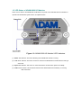
Ethernet-based Data Acquisition and Control Modules
User's Manual
Select Your Hardware Component
Hardware Installation Guide
I/O Module introduction
System Configuration Guide
Plan Your Application Program
Evolved for the eWorld
Copyright Notice
This document is copyrighted, 2002, by Advantech Co., Ltd. All rights are
reserved. Advantech Co., Ltd., reserves the right to make improvements to the
products described in this manual at any time without notice.
No part of this manual may be reproduced, copied, translated or transmitted in any
form or by any means without the prior written permission of Advantech Co., Ltd.
Information provided in this manual is intended to be accurate and reliable.
However, Advantech Co., Ltd. assumes no responsibility for its use, nor for any
infringements upon the rights of third parties which may result from its use.
Acknowledgments
IBM and PC are trademarks of International Business Machines Corporation.
Part No. 2001600000
Printed in Taiwan
First Edition
Mar. 2002
Product Warranty
Advantech warrants to you, the original purchaser, that each of its products will be
free from defects in materials and workmanship for two year from the date of
purchase.
This warranty does not apply to any product which have been repaired or altered by
other than repair personnel authorized by Advantech, or which have been subject to
misuse, abuse, accident or improper installation. Advantech assumes no liability as a
consequence of such events under the terms of this Warranty.
Because of Advantech’s high quality-control standards and rigorous testing, most of
our customers never need to use our repair service. If an Advantech product ever does
prove defective, it will be repaired or replaced at no charge during the warranty period.
For out-of-warranty repairs, you will be billed according to the cost of replacement
materials, service time and freight. Please consult your dealer for more details.
If you think you have a defective product, follow these steps:
1. Collect all the information about the problem encountered (e.g. type of PC, CPU
speed, Advantech products used, other hardware and software used etc.). Note
anything abnormal and list any on-screen messages you get when the problem
occurs.
2. Call your dealer and describe the problem. Please have your manual, product, and
any helpful information readily available.
3. If your product is diagnosed as defective, you have to request an RAM number.
When requesting an RMA (Return Material Authorization) number, please access
ADVANTECH's RMA web site: http://www.advantech.com.tw/rma. If the web
sever is shut down, please contact our office directly. You should fill in the
"Problem Repair Form", describing in detail the application environment,
configuration, and problems encountered. Note that error descriptions such as
"does not work" and "failure" are so general that we are then required to apply our
internal standard repair process.
4. Carefully pack the defective product, a completely filled-out Repair and
Replacement Order Card and a photocopy of dated proof of purchase (such as your
sales receipt) in a shippable container. A product returned without dated proof of
purchase is not eligible for warranty service.
5. Write the RMA number visibly on the outside of the package and ship it prepaid to
your dealer.
Technical Support
We want you to get the maximum performance from your products. So if you run into
technical difficulties, we are here to help. For most frequently asked questions you
can easily find answers in your product documentation. Moreover, there are a huge
database about trouble-shooting and knowledge Base as technical reference on our
website. These answers are normally a lot more detailed than the ones we can give
over the phone.
So please consult this manual or the web site first. If you still cannot find the answer,
gather all the information or questions that apply to your problem and, with the
product close at hand, call your dealer. Our dealers are well trained and ready to give
you the support you need to get the most from your Advantech products. In fact, most
problems reported are minor and are able to be easily solved over the phone.
In addition, free technical support is available from Advantech engineers every
business day. We are always ready to give advice on application requirements or
specific information on the installation and operation of any of our products.
Website information:
You can access the most current support on our website:
http://www.advantech.com
Then click the title of “Service & Support” for further product information.
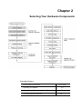
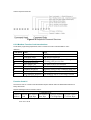
Manual Organization
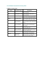
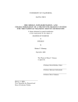
This Manual has six chapters, three appendices.
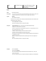
The following table lists each chapter or appendices with its corresponding title and a brief overview of the topics covered in it.
Chapter /
Appendix
Title
Topics Covered
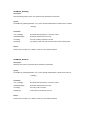
Understanding Your System
Introduces the suitable applying industries and the position
in an Ethernet remote system. Summarize the features and
the common specification of ADAM-6000. Explains the
functions of the LED indicators.
Selecting Your Hardware
Provides a briefly selection chart and specification table of
ADAM-6000 I/O modules for users to organize their
system easily. Give a direction to calculate system capacity
and select a certain power supply. Recommend a standard
for communication cable and connector.
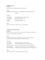
3
Hardware Installation Guide
Lists the necessary components and proper environment in
installing process. Describes the Hardware dimension and
the way to place or mount it. Explains the rule of mapping
I/O address. Describes the wiring and connecting detail for
ADAM-6000.
4
I/O Module Introduction
Introduces the detail specifications, functions and
application wiring of each ADAM-6000 I/O modules.
5
System Configuration Guide
Guides users to use Windows Utility for network &
security setting, I/O range configuration, accuracy
calibration, command setting, and so on.
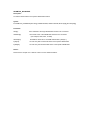
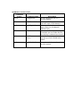
6
Demonstrate the standard web page operation and the
customization web page development. Introduces the
Planning Your Application Program functions and structure of DLL drivers and command sets.
Explain how to integrate these programming tools to plan
your application program.
A
Design Worksheets
Provides organized worksheets for users to establish
system configuration document in order.
B
Data Formats and I/O Range
Provides detail information about Data formats and I/O
Range of Analog Module.
C
Grounding Reference
Explains the concepts about field grounding and shielding.
1
2
How to use this manual
The following flow chart demonstrates a thought process that you can use when you
plan your ADAM-6000 Ethernet Data Acquisition and Control System.
Chapter 1
Understanding Your System
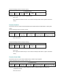
Using this Chapter
If you want to read about
Go to page
Introduction
1-2
Major Feature
1-3
Technical Specification
1-5
LED Status of ADAM-6000 I/O Modules
1-7
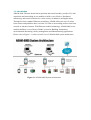
1-1 Introduction
ADAM-6000, Ethernet-based data acquisition and control module, provides I/O, data
acquisition and networking in one module to build a cost-effective, distributed
monitoring, and control solutions for a wide variety of industries and applications.
Through de-factor standard Ethernet networking, ADAM-6000 retrieves I/O values
from sensors and publishes these real-time I/O value to networking nodes at local area
network or Intranet, Internet. With Ethernet-enabled technology, ADAM-6000 series
modules build up a cost-effective DA&C system for Building Automation,
environmental monitoring, facility management and eManufacturing applications.
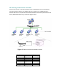
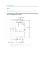
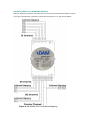
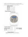
Please refer to Figure 1-1 to have a brief view of ADAM-6000 system architecture.
Figure 1-1 ADAM-6000 System Architecture
1-2 Major Features
1-2-1 Ethernet-enabled DA&C I/O Modules
ADAM-6000 is based on the popular Ethernet networking standards used today in most business
environments. Users can easily add ADAM-6000 I/O modules to existing Ethernet networks or use
ADAM-6000 modules in new Ethernet-enabled eManufacturing networks. ADAM-6000 module features
a 10/100 Mbps Ethernet chip and supports industrial popular Modus/TCP protocol over TCP/IP for data
connection. ADAM-6000 also supports UDP protocol over Ethernet networking. With UDP/IP,
ADAM-6000 I/O modules can actively send I/O data stream to 8 Ethernet nodes. Through Ethernet
networking HMI/SCADA system and controller can access or gather real-time data from ADAM-6000
Ethernet enabled DA&C modules. And, these real-time data can be integrated with business system to
create valuable, competitive business information immediately.
1-2-2 Intelligent I/O Modules
Enhancing from traditional I/O modules, ADAM-6000 I/O modules have pre-built intelligent mathematic
functions to empower the system capacity. The Digital Input modules provide Counter, Totalizer
functions; the Digital Output modules provide pulse output, delay output functions; the Analog Input
modules provide the Max./Min./Average data calculation; the Analog Output modules provide the PID
loop control function.
1-2-3 Mixed I/O in One Module to fit all application’s
ADAM-6000 mixed I/O module design concept provides the most cost-effective I/O usage for application
system. The most common used I/O type for single function unit are collected in ONE module. This
design concept not only save I/O usage and spare modules cost but also speed up I/O relative
operations. For small DA&C system or standalone control unit in a middle or large scale, ADAM-6000
mixed I/O design can easily fit application needs by one or two modules only. With additional embedded
control modules, ADAM-6000 can easily create a localized, less complex, and more distributed I/O
architecture.
1-2-4 Embedded web built web page for remote monitoring and diagnose
Each ADAM-6000 module features a pre-built I/O module web page to display real-time I/O data value,
alarm and module status thru LAN or Internet. Just Internet browser, users can easily monitor real-time
I/O data value and alarm no matter local site or remote site. Then, the web-enabled monitoring system
is completed immediately without any programming effort.
1-2-5 Industrial standard Modbus/TCP protocol supported for open connectivity
ADAM-6000 modules support the popular industrial standard, Modbus/TCP protocol, to connect with
Ethernet Controller or HMI/SCADA software built with Modbus/TCP driver. Advantech also provides
OPC server for Modbus/TCP to integrate ADAM-6000 I/O real-time data value with OPC client enabled
software. Users don’t need to take care of special drivers development.
1-2-6 Customization Web Page
Since ADAM-6000 modules built in a default web page, users has allowed to monitor and control the I/O
status in anywhere through Internet Explorer Browser. Move over, the ADAM-6000 modules could be
downloaded the user-defined web page for individual applications. Advantech has provided sample
programs of JAVA Script for users’ reference to design their own operator interface, then download it into
the specific ADAM-6000 modules via Windows Utility.
1-2-7 Software Support
Based on the Modbus/TCP standard, the ADAM-6000 firmware is a built-in Modbus/TCP server.
Therefore, Advantech provides the necessary DLL drivers, OPC Server, and Windows Utility for users
for client data for the ADAM-6000P. Users can configure this DA&C system via Windows Utility;
integrate with HMI software package via Modbus/TCP driver or Modbus/TCP OPC Server. Even more,
you can use the DLL driver and ActiveX to develop your own applications.
1-3 Common technical specification of ADAM-6000
• Ethernet: 10 BASE-T IEEE 802.3
100 BASE-TX IEEE 802.3u
• Wiring: UTP, category 5 or greater
• Bus Connection: RJ45 modular jack
• Comm. Protocol: Modbus/TCP on TCP/IP and UDP
• Data Transfer Rate: Up to 100 Mbps
• Unregulated 10 to 30VDC
• Protection: Over-voltage and power reversal
• Ethernet Communication: 1500 V DC
• I/O Module: 3000 V DC
• Status Indicator:
Power, CPU, Communication (Link, Collide, 10/100 Mbps, Tx, Rx)
• Case: ABS with captive mounting hardware
• Plug-in Screw Terminal Block:
Accepts 0.5 mm 2 to 2.5 mm 2 , 1 - #12 or 2 - #14 to #22 AWG
• Operating Temperature: - 10 to 70º C (14 to 158º F)
• Storage Temperature: - 25 to 85º C (-13 to 185º F)
• Humidity: 5 to 95%, non-condensing
• Atmosphere: No corrosive gases
NOTE: Equipment will operate below 30% humidity. However, static electricity problems occur much
more frequently at lower humidity levels. Make sure you take adequate precautions when you
touch the equipment. Consider using ground straps, anti-static floor coverings, etc. if you use the
equipment in low humidity environments.
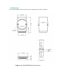
1-4 Dimensions
The following diagrams show the dimensions of the ADAM-6000 l/O module in millimeters.
Figure 1-2: ADAM-6000 Module Dimension
1-5 LED Status of ADAM-6000 I/O Modules
There are two LEDs on the ADAM-6000 I/O Modules front panel. Each LEDs built with two indicators to
represent the ADAM-6000 system status, as explained below:
Figure 1-3: ADAM-6000 I/O Modules’ LED Indicators
(1) Status: Red indicator. This LED is blanking when ADAM-6000 module is running.
(2) Link: Green indicator. This LED is normal on whenever the ADAM-6000 module’s Ethernet wiring is
connected.
(3) Speed: Red indicator. This LED is on when the Ethernet communication speed is 100 Mbps.
(4) COM: Green indicator. This LED blinks whenever the ADAM-5000/TCP transmitting or receiving
data on Ethernet.
Chapter 2
Selecting Your Hardware Components
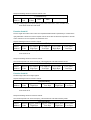
Using this Chapter
If you want to read about
Selecting I/O Module
Go to page
2-2
Selecting Link Terminal & Cable (Ethernet)
2-3
Selecting Operator Interface
2-4
2-1 Selecting I/O Module
To organize an ADAM-6000 remote data acquisition & control system, you need to select I/O modules to interface the host
PC with field devices or processes that you have previously determined. There are several things should be considered
when you select the I/O modules.
What type of I/O signal is applied in your system?
How much I/O is required to your system?
How will you place the I/O Modules to handle the I/O points in individual area of an entire field site.
How many ADAM-6000 I/O modules are required for distributed I/O points arrangement.
How many hubs are required for the connection of these Ethernet devices?
What is the required voltage range for each I/O module?
What isolation environment is required for each I/O module?
What are the noise and distance limitations for each I/O module?
Refer to table 2-1 as I/O module selection guidelines
Choose this type of
I/O module:
For these types of field
devices or operations
(examples):
Explanation:
Discrete input
module and block
I/O module
Selector switches,
pushbuttons, photoelectric
eyes, limit switches, circuit
breakers, proximity
switches, level switches,
motor starter contacts, relay
contacts, thumbwheel
switches
Input modules sense ON/OFF or
OPENED/CLOSED signals.
Discrete output
module and block
I/O module
Alarms, control relays,
fans, lights, horns, valves,
motor starters, solenoids
Output module signals interface with
ON/OFF or OPENED/CLOSED devices.
Analog input
module
Thermocouple signals,
RTD signals, temperature
transducers, pressure
transducers, load cell
transducers, humidity
transducers, flow
transducers, potentiometers.
Convert continuous analog signals into
input values for host device
Analog output
module
Analog valves, actuators,
chart recorders, electric
motor drives, analog meters
Interpret host device’s output to analog
signals (generally through transducers)
for field devices.
Table 2-1 I/O Selection Guidelines
2-2 Selecting Link Terminal and Cable
Use the RJ-45 connector to connect the Ethernet port of the ADAM-6000 to the Hub. The cable for
connection should be Category 3 (for 10Mbps data rate) or Category 5 (for 100Mbps data rate)
UTP/STP cable, which is compliant with EIA/TIA 586 specifications. Maximum length between the Hub
and any ADAM-6000 modules is up to 100 meters (approx. 300 ft).
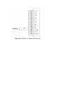
Figure 2-1 Ethernet Terminal and Cable Connection
PIN NUMBER
1
2
3
4
5
6
7
8
SIGNAL
RD+
RDTD+
(Not Used)
(Not Used)
TD(Not Used)
(Not Used)
FUNCTION
Receive (+)
Receive (-)
Transmit (+)
Transmit (-)
-
Table 2-2 Ethernet RJ-45 port Pin Assignment
2-3 Selecting Operator Interface
To complete your data acquisition and control system, selecting the operator interface is necessary.
Adopting by Modbus/TCP Protocol, ADAM-6000 I/O modules exhibit high ability in system integration for
various applications.
If you want to read the real-time status of ADAM-6000 modules through the web page from anywhere
without any engineering effort, there are many Internet browser software:
Internet Explorer, Netscape, and other browser with JAVA Machine…
If you want to develop your own web pages in the ADAM-6000 modules, the JAVA Script will be the
quick and easy programming tool to design a specific operator interface.
J2EE Development Kit
If you want to integrate ADAM-6000 I/O with HMI (Human Machine Interface) software in a SCADA
(Supervisory Control and Data Acquisition) system, there are a lot of HMI software packages, which
support Modbus/TCP driver.
Advantech Studio
Wonderware InTouch
Intellution Fix of i-Fix
Any other software support Modbus/TCP protocol
Moreover, Advantech also provides OPC Server, the most easy-to-use data exchange tool in worldwide.
Any HMI software designed with OPC Client would be able to access ADAM-6000 I/O modules.
Modbus/TCP OPC Server
If you want to develop your own application, the DLL driver and ActiveX will be the best tools to build up
user’s operator interface.
ADAM-6000 DLL driver
ADAM-6000 ActiveX
With these ready-to-go application software packages, tasks such as remote data acquisition, process
control, historical trending and data analysis require only a few keystrokes.
Chapter 3
Hardware Installation Guide
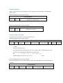
Using this Chapter
If you want to read about
Go to page
Determining the proper environment
3-2
Module Mounting
3-3
Wiring and Connection
3-7
3-1 Determining the proper environment
Before you start to install the ADAM-6000 modules, there are something needed to check.
3-1-1 Check the content of shipping box
Unpack the shipping boxes and make sure that the contents include:
ADAM-6000 module with one bracket and DIN Rail adapter
ADAM-6000 module User’s Notes
3-1-2 System Requirements
Host computer
-
IBM PC compatible computer with 486 CPU (Pentium is recommended)
-
Microsoft 95/98/2000/NT 4.0 (SP3 or SP4)/XP or higher versions
-
At least 32 MB RAM
-
20 MB of hard disk space available
-
VGA color monitor
-
2x or higher speed CD-ROM
-
Mouse or other pointing devices
-
10 or 100 Mbps Ethernet Card
10 or 100 Mbps Ethernet Hub (at least 2 ports)
Two Ethernet Cable with RJ-45 connector
Power supply for ADAM-6000 (+10 to +30 V unregulated)
3-2 Mounting
The ADAM-6000 modules designed with compact size and allowed to install in the field site as following
methods.
3-2-1 Panel mounting
Each ADAM-6000 Module has packed with a plastic panel mounting bracket. Users can refer the
dimension of the bracket to configure an optimal placement in the panel or cabinet. Fix the bracket first,
then, fix the ADAM-6000 module on the bracket.
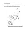
Figure 3-1: ADAM-6000 panel mounting dimension
Figure 3-2: Fix ADAM-6000 module on the bracket
3-2-2 DIN rail mounting
The ADAM-6000 module can also be secured to the cabinet by using mounting rails. Fix the
ADAM-6000 module with the DIN Rail adapter as figure 3-3. Then secured it on the DIN rail as figure
3-4. If you mount the module on a rail, you should also consider using end brackets at each end of the
rail. The end brackets help keep the modules from sliding horizontally along the rail.
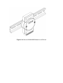
Figure 3-3: Fix ADAM-6000 module on the DIN rail adapter
Figure 3-4: Secure ADAM-6000 Module to a DIN rail
3-3 Wiring and Connections
This section provides basic information on wiring the power supply, I/O units, and network connection.
3-3-1 Power supply wiring
Although the ADAM-6000/TCP systems are designed for a standard industrial unregulated 24 V DC
power supply, they accept any power unit that supplies within the range of +10 to +30 VDC. The power
supply ripple must be limited to 200 mV peak-to-peak, and the immediate ripple voltage should be
maintained between +10 and +30 VDC. Screw terminals +Vs and GND are for power supply wiring.
Note: The wires used should be sized at least 2 mm.
Figure 3-5: ADAM-6000 Module power wiring
We advise that the following standard colors (as indicated on the modules) be used for power lines:
+Vs (R)
Red
GND (B)
Black
3-3-2 I/O modules wiring
The system uses a plug-in screw terminal block for the interface between I/O modules and field devices.
The following information must be considered when connecting electrical devices to I/O modules.
1. The terminal block accepts wires from 0.5 mm to 2.5 mm.
2. Always use a continuous length of wire. Do not combine wires to make them longer.
3. Use the shortest possible wire length.
4. Use wire trays for routing where possible.
5. Avoid running wires near high-energy wiring.
6. Avoid running input wiring in close proximity to output wiring where possible.
7. Avoid creating sharp bends in the wires.
Figure 3-6: ADAM-6000 I/O Module Terminal Block wiring
Chapter 4
I/O Module Introduction
Using this Chapter
If you want to read about
Go to page
Analog Input Module
4-2
Digital Input / Output Module
4-7
4-1 Analog Input Module
Analog input modules use an A/D converter to convert sensor voltage, current, thermocouple or RTD
signals into digital data. The digital data is then translated into engineering units. When prompted by the
host computer, the data is sent through a standard 10/100 based-T Ethernet interface. Users would able
to read the current status via pre-built web page or any HMI software package supported Modbus/TCP
protocol. The analog input modules protect your equipment from ground loops and power surges by
providing opto-isolation of the A/D input and trans-former based isolation up to 3,000 VDC .
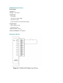
ADAM-6017 8-channel Analog Input with 2/DO Module
The ADAM-6017 is a 16-bit, 8-channel analog differential input module that provides programmable
input ranges on all channels. It accepts millivoltage inputs (±100mV, ±500mV), voltage inputs (±1V, ±5V
and ±10V) and current input (±20 mA, 4~20 mA) and provides data to the host computer in engineering
units (mV, V or mA). In order to satisfy all plant needs in one module, ADAM-6017 has designed with 8
analog inputs and 2 digital outputs. Each analog channel is allowed to configure an individual range for
variety of applications.
ADAM-6017
Figure 4-1: ADAM-6017 8-channel Analog Input w/2DO Module
ADAM-6017 Specification
Analog Input:
• Effective resolution: 16-bit
• Channels: 8 differential
• lnput type: mV, V, mA
• lnput range: ±150 mV, ±500 mV, ±1 V, ±5 V, ±10 V, 0-20 mA, 4-20 mA
• Isolation voltage: 3000 VDC
• Fault and overvoltage protection: Withstands overvoltage up to ±35 V
• Sampling rate: 10 samples/sec.
• Input impedance: 20 M ohm
• Bandwidth: 13.1 Hz @ 50 Hz, 15.72 Hz @ 60 Hz
• Accuracy: ±0.1% or better
• Zero drift: ±6 µV/° C
• Span drift: ±25 ppm/° C
• CMR @ 50/60 Hz: 92 dB min.
Digital Output:
• Channel: 2
Open Collector to 30 V
200 mA max. load
• Optical Isolation: 5000VRMS
Built-in Watchdog Timer
Power
• Power requirements: Unregulated +10 ~ +30 VDC
• Power consumption: 2 W
Application Wiring
Figure 4-2: ADAM-6017 millivoltage, voltage, and current Input Wiring
ADAM-6017 has built with a 120 ohms resistor in each channel, users do not have to add any resistors
in addition for current input measurement. Just adjust the jumper setting to choose the specific input
type you need. Refer to Figure 4-3, each analog input channel has built-in a jumper on the PCB for
users to set as a voltage mode or current mode.
Figure 4-3: ADAM-6017 Analog Input Type Setting
Figure 4-4: ADAM-6017 Digital Output wiring
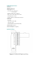
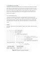
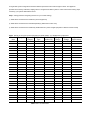
Assigning address for ADAM-6017 Modules
Basing on Modbus/TCP standard, the addresses of the I/O channels in ADAM-6000 modules you place
in the system are defined by a simple rule. Please refer the Figures 4-5 to map the I/O address.
Figure 4-5: ADAM-6017 I/O Address Mapping
4-2 Digital I/O Module
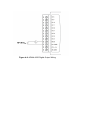
ADAM-6050 18-channel Digital I/O Module
The ADAM-6050 is a high-density I/O module built-in a 10/100 based-T interface for seamless Ethernet
connectivity. It provides 12 digital input and 6 digital output channels with 5000VRMS Isolating protection.
All of the Digital Input channels support input latch function for important signal handling. Mean while,
these DI channels allow to be used as 1 KHz counter. Opposite to the intelligent DI functions, the Digital
Output channels also support pulse output function.
ADAM-6050
Figure 4-6: ADAM-6050 18-channel Digital I/O Module
ADAM-6050 Specification
Analog Input:
• Channel: 18
• I/O type: 12 DI & 6 DO
• Digital Input:
Dry Contact:
Logic level 0: Close to GND
Logic level 1: Open
(Logic level status can be inversed by Utility)
• Digital Output:
Open Collector to 30 V
200 mA max. load
• Optical Isolation: 5000VRMS
• Power Consumption: 2 W (Typical)
Application Wiring
Figure 4-7: ADAM-6050 Digital Input Wiring
Figure 4-8: ADAM-6050 Digital Output Wiring
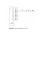
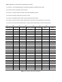
Assigning address for ADAM-6050 Modules
Basing on Modbus/TCP standard, the addresses of the I/O channels in ADAM-6000 modules you place
in the system are defined by a simple rule. Please refer the Figures 4-10 to map the I/O address.
Figure 4-9 ADAM-6050 I/O Address Mapping
All Digital Input channels in ADAM-6050 are allowed to use as 32-bit counters (Each counter is
consisted of two addresses, Low word and High word). Users could configure the specific DI channels to
be counters via Windows Utility. The I/O address will be mapped as Figures 4-10.
Figure 4-10 ADAM-6050 Counter Address Mapping
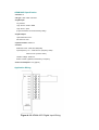
ADAM-6051 16-channel Digital I/O w/Counter Module
The ADAM-6051 is a high-density I/O module built-in a 10/100 based-T interface for seamless Ethernet
connectivity. It provides 12 digital input, 2 digital output, and 2 counter (10 KHz) channels with 5000VRMS
Isolating protection. All of the Digital Input channels support input latch function for important signal
handling. Mean while, these DI channels allow to be used as 1 KHz counter. Opposite to the intelligent
DI functions, the Digital Output channels also support pulse output function.
ADAM-6051
Figure 4-11: ADAM-6051 16-channel Digital I/O w/Counter Module
ADAM-6051 Specification
• Channel: 16
• I/O type: 12DI / 2DO / 2Counter
• Digital Input:
Dry Contact:
Logic level 0: Close to GND
Logic level 1: Open
(Logic level status can be inversed by Utility)
• Digital Output:
Open Collector to 30 V
200 mA max. load
• Optical Isolation: 5000VRMS
• Counter:
Maximum Count: 4,294,967,285(32 bit)
Input frequency: 0.3 ~ 1000 Hz max. (frequency mode)
5000 Hz max. (counter mode)
Isolation voltage: 2500 VRMS
Mode: Counter (Up/Down, Bi-direction), Frequency
• Power Consumption: 2 W (Typical)
Application Wiring
Figure 4-12: ADAM-6051 Digital Input Wiring
Figure 4-13: ADAM-6051 Digital Output and Counter Wiring
Assigning address for ADAM-6051 Modules
Basing on Modbus/TCP standard, the addresses of the I/O channels in ADAM-6000 modules you place
in the system are defined by a simple rule. Please refer the Figures 4-14 to map the I/O address.
Figure 4-14: ADAM-6051 I/O Address Mapping
All Digital Input channels in ADAM-6051 are allowed to use as 32-bit counters (Each counter is
consisted of two addresses, Low word and High word). Users could configure the specific DI channels to
be counters via Windows Utility. The I/O address will be mapped as Figures 4-15.
Figure 4-15: ADAM-6051 Counter Address Mapping
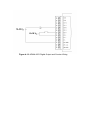
ADAM-6060 6-channel Relay Output with DI Module
The ADAM-6060 is a high-density I/O module built-in a 10/100 based-T interface for seamless Ethernet
connectivity. Bonding with an Ethernet port and web page, the ADAM-6060 offers 6 relay (form A) output
and 6 digital input channels. It supports contact rating as AC 120V @ 0.5A, and DC 30V @ 1A. All of the
Digital Input channels support input latch function for important signal handling. Mean while, these DI
channels allow to be used as 1 KHz counter. Opposite to the intelligent DI functions, the Digital Output
channels also support pulse output function.
ADAM-6060
Figure 4-16: ADAM-6060 6-channel Relay Output w/DI Module
ADAM-6060 Specification
• Channel: 12
• I/O type: 6 Relay & 6 DI
• Relay Output (Form A):
Contact rating: AC: 120 V @ 0.5 A
DC: 30 V @ 1 A
Breakdown voltage: 500 VAC (50/60 Hz)
Relay on time: 7 msec; Relay off time: 3 msec.
Total switching time: 10 msec.
Insulation resistance: 1000 MW minimum at 500 VDC
• Digital Input:
Dry Contact:
Logic level 0: Close to GND
Logic level 1: Open
(Logic level status can be inversed by Utility)
• Optical Isolation: 5000VRMS
• Power Consumption: 2 W (Typical)
Application Wiring
Figure 4-17: ADAM-6060 Digital Input Wiring
Figure 4-18: ADAM-6060 Relay Output Wiring
Assigning address for ADAM-6060 Modules
Basing on Modbus/TCP standard, the addresses of the I/O channels in ADAM-6000 modules you place
in the system are defined by a simple rule. Please refer the Figures 4-19 to map the I/O address.
Figure 4-19: ADAM-6060 I/O Address Mapping
All Digital Input channels in ADAM-6060 are allowed to use as 32-bit counters (Each counter is
consisted of two addresses, Low word and High word). Users could configure the specific DI channels to
be counters via Windows Utility. The I/O address will be mapped as Figures 4-20.
Figure 4-20: ADAM-6060 Counter Address Mapping
Chapter 5
System Configuration Guide
Using this Chapter
If you want to read about
Go to page
System Hardware Configuration
5-2
Install Utility Software
5-3
I/O Module Configuration
5-10
I/O Module Calibration
5-17
Security Setting
5-18
Technical Emulation
5-19
This chapter explains how to use ADAM Ethernet I/O Utility to configure the ADAM-6000 modules for
various applications. Users can learn the hardware connection, software installation, communication
setting and every procedure for system configuration from these sections.
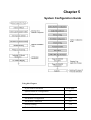
5-1 System Hardware Configuration
As we mentioned in chapter 3-1, you will need following items to complete your system hardware
configuration.
System Requirement
Host computer
-
IBM PC compatible computer with 486 CPU (Pentium is recommended)
-
Microsoft 95/98/2000/NT 4.0 (SP3 or SP4) or higher versions
-
At least 32 MB RAM
-
20 MB of hard disk space available
-
VGA color monitor
-
2x or higher speed CD-ROM
-
Mouse or other pointing devices
-
10 or 100 Mbps Ethernet Card
10 or 100 Mbps Ethernet Hub (at least 2 ports)
Two Ethernet Cable with RJ-45 connector
Power supply for ADAM-6000 (+10 to +30 V unregulated)
Make sure to prepare all of the items above, then connect the power and network wiring as figure 5-1.
Figure 5.1 Hardware Configuration
5-2 Install Utility Software on Host PC
Advantech provide free download Manual and Utility software for ADAM-6000 modules’ operation and
configuration. Link to the web site: www.advantech.com and click into the “Download Area” under
Service & Support site to get the latest version ADAM-6000 manual and Ethernet I/O Utility.
Once you download and setup the Utility software, there will be a shortcut of the Utility executive
program on Windows’ desktop after completing the installation.
Notes: This Utility would be able to support ADAM-5000/TCP and ADAM-6000 I/O modules.
5-3 ADAM Ethernet I/O Utility Overview
The Utility software offers a graphical interface that helps you configure the ADAM-6000 modules. It is
also very convenient to test and monitor your Remote DA&C System. The following guidelines will give
you some brief instructions on how to use this Utility.
● Main Menu
●
Network Setting
●
Adding Remote Station
●
I/O Module Configuration
●
Alarm Setting
●
I/O Module Calibration
●
Firmware and Web Page Update
●
Security Setting
●
Terminal emulation
●
Data Stream
●
RS-458 Modbus Network Setting
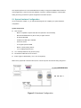
5-3-1 Main Menu
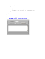
Double Click the icon of ADAM Ethernet I/O Utility shortcut, the Operation screen will pop up as Figure
5-2.
Figure 5-2 Operation Screen
The top of the operation screen consists of a function menu and a tool bar for user’s commonly
operating functions.
Function Menu
Item File contents “Exit” Function, using to exit this Utility program.
Item Tool contents functions as below:
Add Remote Ethernet Device Create a new ADAM-6000 module or ADAM-5000/TCP located in other
Ethernet domination, both available to local LAN and Internet
application.
Search for Ethernet Device Search all ADAM-6000 and ADAM-5000/TCP units in the specific Ethernet
domination. (The same with host PC’s Ethernet domination)
Refresh a Ethernet Device Refresh the specific ADAM-6000 or ADAM-5000/TCP unit to verify the
system status.
Terminal Call up the operation screen of Terminal emulation to do the request / response command
execution.
Item Setup contents Timeout and Scan Rate setting functions. Please be aware of the time setting for
other Ethernet domination usually longer than local network.
Item Help contents on-line help function as user’s operation guide; the item About contents
information about software version, released date, and support modules.
Tool Bar
There are five push buttons in the tool bar.
Figure 5-3 Tool Bar
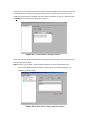
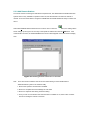
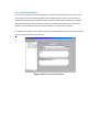
5-3-2 Network Setting
As the moment you start up this Windows Utility, it will search all ADAM-6000 I/O modules and
ADAM-5000/TCP on the host PC’s domination Ethernet network automatically. Then the tree-structure
display area will appeal with the searched units and the relative IP address.
Figure 5-4 Network Setting
See Figure 5-4, there are also Host PC’s information in the status display area, include host name and
IP address. Moreover, the Windows Utility provides network connection test tool for user to verify
whether the communication is workable. Key-in the specific IP address you want to connect and click
the PING button, the testing result will show as Figure 5-5.
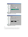
Figure 5-5 Communication testing function
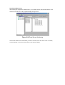
Since Utility software detects the ADAM-6000 and 5000/TCP on the network, user can begin to setup
each unit with following steps.
Step1. Choose any one station, all I/O modules plugged in the main unit will be listed on the
tree-structure display area. Mean while, the “Device Name” and “Device Description” are
editable by operator’s needs.
Figure 5-6 Define Device Name and Description
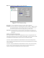
Step2. Click the Network Tab to configure the TCP/IP network setting
Figure 5-7 TCP/IP Network setting
MAC Address This is also called Ethernet address and needs no further configuration.
Link Speed This function will show the current linking speed to be either 10Mbps or 100Mbps. However,
the utility will auto-detect the current transmission speed on the network segment and set
the transmission speed for the device accordingly without your further efforts.
Duplex Mode The utility will detect the current transmission mode (half-duplex or full-duplex) on the
network segment, and set the transmission mode for the device accordingly without your
further efforts.
IP Address, Subnet Mask, Default Gateway
The IP address identifies your ADAM-6000 and ADAM-5000/TCP devices on the global network. Each
ADAM-6000 and ADAM-5000/TCP has same default IP address 10.0.0.1. Therefore, please do not initial
many ADAM-6000 and ADAM-5000/TCP at the same time to avoid the Ethernet collision.
If you want to configure the ADAM-6000 and ADAM-5000/TCP in the host PC’s dominating network,
only the IP address and Subnet Mask will need to set (The host PC and ADAM Ethernet I/O must belong
to same subnet Mask).
If you want to configure the ADAM-6000 and ADAM-5000/TCP via Internet or other network domination,
you have to ask your network administrator to obtain a specific IP and Gateway addresses, then
configure each ADAM-6000 and ADAM-5000/TCP with the individual setting.
5-3-3 Add Remote Stations
To meet the remote monitoring and maintenance requirements, The ADAM-6000 and ADAM-5000/TCP
System does not only available to operate in local LAN, but also allowed to access from Internet or
Intranet. Thus users would able to configure an ADAM-6000 and ADAM-5000/TCP easily no matter how
far it is.
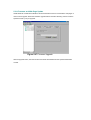
Select item Tool\Add Remote Ethernet I/O in function menu or click the
button, the adding station
screen will pop up as Figure 5-8. Then key-in the specific IP address and click the Add button. If the
communication success, the added ADAM Ethernet I/O unit should appeal on the tree-structure display
area.
Figure 5-8 Adding ADAM Ethernet I/O Screen
Note
There are several conditions need to be sure before adding a remote ADAM-6000 or
ADAM-5000/TCP system in the windows Utility.
1. Be sure the specific IP is existed and available.
2. Be sure to complete the network linkage for both sides.
3. Be sure to adjust the best timing of timeout setting.
4. Even you are not sure whether the communication is workable or not, there is also a “PING”
function for testing the network connection.
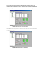
5-3-4 I/O Module Configurations
Digital Input Output Module
Selecting ADAM-6000 Digital Modules includes ADAM-6050/605/6060, user can read following
information from the Utility.
Figure 5-9 Digital I/O Module Configuration
Location Standard Modbus address. ADAM Ethernet I/O Utility shows the Modbus mapping address of
each I/O channel. (Please refer to chapter 4 to see the address mapping for I/O Modules)
And the addresses will be the indexes for applying into the database of HMI or OPC Server.
Type Data Type of the I/O channel. The data type of Digital I/O modules is always “Bit”.
Value The current status on each channel of I/O Module. The value of digital I/O modules could be “0”
(OFF) or “1” (ON).
Description Describes the channel numbers and I/O types of the specific module.
In addition to monitor the current DI/DO status, the Windows Utility offers a graphical operating interface
as figure 5-10. You can read the Digital input status through the change of the indicator icons.
Oppositely, you can write the digital output status through clicking the indicator icons.
Figure 5-10 Operating and Indicating Icons
Note 1 The indicator icons are only available to click for digital output channel.
2 The hexadecimal code will be calculated automatically for any status.
With intelligent design concept, the digital input channels support counter and signal latch functions.
Click the specific channel, there will be four working modes for choosing.
Figure 5-11 General Digital Input Mode
Figure 5-12 Counter Input Mode
Figure 5-13 Latch Input Mode
Note:
1)
The new working mode setting will take effective after click the “Update” button.
2)
If necessary, users could invert the original single for flexible operation needs.
The digital output channels support pulse output and delay output functions. Click the
specific channel, there will be four working modes for choosing.
Figure 5-14 Pulse Output Mode Setting
Figure 5-15 Delay Output Mode Setting
Analog Input Module
Selecting ADAM-6000 Analog Input Modules includes ADAM-6017, users can read following information
from the Utility.
Figure 5-16 Current Analog Input Status
Location Standard Modbus address. (Refer to Assigning address for I/O module in Chapter 4)
Type Data type of the I/O channel. The data type of analog Input modules is always “word”.
Value The current status on each channel of I/O modules. Windows Utility provides both decimal and
hexadecimal values used for different applications.
Description Describes the channel numbers, sensor types, and measurement range of the specified
module.
Before acquiring the current data of an analog input module, you have to select the input range and
integration time. Then the input data will be scaled as the specified range with engineer unit.
Figure 5-17 setting range and integration time
Note Windows Utility allows user to Enable / Disable the current status display.
To provide users more valuable information, the ADAM-6000 analog modules have designed with
calculation functions, includes Maximum, Minimum, and Average values of individual channels. Click the
Maximum value tab, you will see the historical maximum values in each channel unless to press the
against “Reset” buttons.
Figure 5-18 Maximum Value Recording
Click the Minimum value tab, you will see the historical minimum values in each channel unless to press
the against “Reset” buttons.
Figure 5-19 Minimum Value Recording
Moreover, all of the analog channels are allowed to configure the High/Low limitation for alarm trigger
function. Once the value of the specific channel over or under the limitation, the alarm status could
trigger a digital output channel in the ADM-6017.
Figure 5-20 Alarm Setting
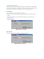
5-3-5 I/O Module Calibrations
Calibration is to adjust the accuracy of ADAM module. There are several modes for module’s calibration:
Zero calibration, Span calibration, CJC calibration, and Analog Output calibration. Only analog input and
output modules can be calibrated, and the ADAM-6017 is the first released analog module.
Zero Calibration
1. Apply power to the module and let it warm up for 30 minutes.
2. Make sure the module is correctly installed and properly configured for the input range you want to
calibrate.
3. Use a precision voltage source to apply a calibration voltage to the V+ and V- terminals of the
ADAM-6017 module.
4. Click the Execute button.
Figure 5-21 Zero Calibration
Span Calibration
Follow the same procedure of zero calibration and click the Execute button.
Figure 5-22 Span Calibration
5-3-6 Security Setting
Though the technology of Ethernet discovered with great benefits in speed and integration, there also
exist risk about network invading form anywhere. For the reason, the security protection design has
built-in ADAM-6000 I/O modules. Once user setting the password into the ADAM-6000 firmware, the
important system configurations (Network, Firmware, Password) are only allowed to be changed by
password verification.
Figure 5-23 Password Setting
Note: The default password of ADAM-6000 is “00000000”. Please make sure to keep the correct
password by yourself. If you lose it, please contact to Advantech’s technical support center for
help.
5-3-7 Terminal Emulations
You can issue commands and receive response by clicking the Terminal button on the tool bar. There
are two kinds of command format supported by this emulating function. Users can choose ASCII or
Hexadecimal mode as their communication base. If the ASCII mode has been selected, the Windows
Utility will translate the request and response string both in Modbus and ASCII format. Please refer
Chapter 6-2 to use Modbus Command; and refer Chapter 6-4 to apply ASCII command.
For example, select ASCII mode and key-in the ASCII command “$01M” (read module name), then click
Send. The response will show as figure 5-24.
Figure 5-24 Command Emulation
5-3-8 Data Stream
Data Stream Configuration
In addition to TCP/IP communication protocol, ADAM-6000 supports UDP communication protocol to
regularly broadcast data to specific host PCs.
Click the tab of Data Stream, then configure the broadcasting interval and the specific IP addresses
which need to receive data from the specific ADAM-6000 I/O module. This UDP Data Stream function
broadcasts up to 8 host PCs simultaneously, and the interval is user-defined from 50ms to 7 Days.
Figure 5-25 Data Stream Configuration
Data Stream Monitoring
After finishing the configuration of Data Stream, you can select the item “Monitor Data Stream” in the
function bar or click icon to call up operation display as Figure 5-26.
Figure 5-26 Data Stream Monitoring
Select the IP address of the ADAM-6000 you want to read data, then click “Start ” button. The Utility
software will begin to receive the stream data on this operation display.
5-3-9 Firmware and Web Page Update
ADAM-6000 I/O modules are available to remote download firmware for customization web pages or
new functions upgrade. Select the Firmware Upgrade tab and click the “Browsing” button to find the
specific firmware (*.bin) for upgrade.
Figure 5-27 Firmware Upgrade
Click the upgrade button, then the new firmware will be downloaded into the specific ADAM-6000
module.
Instructions to Java Applet Customization
Introduction
In this section, we will tell you the way to create an applet web page to monitor the status of ADAM-6060
through the Web browser. To write an input processing applet, you need to know how to define a class
with multiple methods. To understand how an applet processes input data, you must learn what events
are and how events are handled in Java programs. We don’t intend to teach you how to write the applet
because it is beyond the scope of our discussion here. Instead, we will provide you with a
small-but-useful example as well as the relevant class, methods and suggested template. We refer the
interested user who is intended to know more details to the following web site
http://java.sun.com/docs/books/tutorial/.
To write an applet that is capable of processing ADAM-6060 input data in a very short time, we provide
you with a class which includes all necessary methods. The kernel functions/methods to communicate
with our product and display the current, updated status has been fine-tuned for any signal it can process.
Four major methods are developed for the purpose, listed in table 1.
♦ boolean ForceCoil(int CoilAddr, boolean IsTrunOn)
This method is used for digital output of module channels. The parameter CoilAddr
is integer data type and the coil address of the channel. IsTrueOn is the parameter
used to indicate ON or OFF. If the method is successful, it will return true.
♦ boolean ReadCoil(int StartingAddr, int NoOfPoint, byte ModBusRTU[])
This method is used for digital input of module channels. The parameter
StartingAddr is the starting address of desired channel. NoOfPoint is to indicate
how many desired channels to be monitored. Both of the parameters are of integer
data type. The third parameter, ModBusRTU is an array with data type of byte,
which is used to carry digital inputs of the desired channels. The default size is 128.
♦ boolean ReadRegister(int StartingAddr, int NoOfPoint, byte ModBusRTU[])
This method is used for analog input of module channels. The parameter
StartingAddr is the starting address of desired channel. NoOfPoint is to indicate
how many desired channels to be monitored. Both of the parameters are of integer
data type. The third parameter, ModBusRTU is an array with data type of byte,
which is used to carry analog inputs of the desired channels. The default size is
128.
Table 1. Useful Methods to Communicate ADAM-6000 I/O Series Modules for
Digital I/O and Analog I/O
Employing these four methods, you can customize your applet and focus solely on the user interface you
intend to create and the number of channels you want to monitor.
An Example
To process ADAM-6060 input and display the result/status on an applet, we will use objects from the
standard java class library and the class we develop. Specifically, we provide Modbus class to handle the
communication with ADAM-6000 I/O modules. Now we’re going to teach you step by step how to
customize your Web page.
Java Applet Programming
To create your own Web page, you have to follow some rules. There are two parts in this section. We
start from the HTML file. Please refer to table 2 below for the default HTML source code.
<HTML>
<HEAD>
<TITLE>
ADAM-6000 Ethernet-Enabled DA&C Modules
</TITLE>
</HEAD>
<BODY>
<APPLET
CODEBASE = "."
CODE
= "Adam6060.class"
ARCHIVE = "Adam6060.jar"
NAME
= "Adam6060 Relay Module"
WIDTH
= 500
HEIGHT = 400
HSPACE
=0
VSPACE
=0
ALIGN
= middle
>
<PARAM NAME = "HostIP" VALUE = "010.000.000.000">
</APPLET>
</BODY>
</HTML>
Table 2. Overview of index.html
Firstly, the HTML file must be named “index.html.” The name of parameter in <APPLET…> cannot
change. The lines “CODE = "Adam6060.class"” and “ARCHIVE = "Adam6060.jar"” indicate where the
class and jar files (your Java Applet program) are for ADAM-6060 module. WIDTH and HEIGHT are
parameters to set the visible screen size of your Java Applet Web page. The HTML is a good template for
you to create your own embedded Web page; however, the parameter names and most of their values
cannot be modified, or it will not work. You can only change the value of WIDTH and HEIGHT parameters,
e.g. WIDTH = 640 and HEIGHT = 480. However, you must change the value of CODE and ARCHIVE
when you try to write it for another module, say ADAM-6017, and thus you should use “Adam6017.class”
and “Adam6017.jar” instead of “Adam6060.class” and “Adam6060.jar.”
Some Instructions When Writing Java Applet for ADAM-6000 I/O Series
To enable your java applet to communicate with ADAM-6000 I/O modules, you have to include the
following code in the very beginning of your program:
import Adam.ModBus.*;
In constructor it is suggested to add the following fragment in your exception handler:
Try {
HostIP = getParameter("HostIP");
Adam6060Connection = new ModBus(HostIP);
if (HostIP == "")
labAdamStatusForDIO.setText("Get Host IP is null !!");
else
labAdamStatusForDIO.setText("Get Host IP :" +
Adam6060Connection.GetHostIP() + " Ver 1.00");
………………
}
The fragment is used to obtain the host IP value and check if it is null. To acquire the necessary
parameter information from the index.html, you need to add the fragment below.
public String[][] getParameterInfo() {
String[][] pinfo =
{
{"HostIP", "String", ""},
};
return pinfo;
}
As for mouse/keyboard events and graphical user interface, they are beyond the scope of our discussion
here and we will leave them to users.
After you finish your program and compile, it should generate a couple of classes, e.g. ADAM6060.class,
ADAM6060$1.class, ADAM6060$2, and myFramPanel.class in our example. Then, follow the standard
way to combine the generated classes with ModBus.class which must be placed in the directory path
“Adam/ModBus/” into a jar file. In this case, the name for the file should be ADAM6060.jar. The figure
below shows the structure to make the jar file.
Figure 5-28 The structure of ADAM6060.jar file
Start your ADAM utility, and open the tab “Firmware/Web” as shown below. Then, tell the utility where the
path is for the JAR and HTML files. In this case, they are ADAM-6060.jar and index.html. Push
button, and a confirmation window pops up. After you confirm, it will start processing.
Figure 5-29 Firmware Upgrade for ADAM-6000 I/O Series Modules
Appendix A
Source Code of Java Applet Example
import Adam.ModBus.*;
import java.awt.*;
import java.awt.event.*;
import java.applet.*;
import java.io.*;
import java.lang.*;
public class Adam6060 extends Applet {
boolean isStandalone = false;
String var0;
Thread AdamPoilThread;
String HostIP;
long ErrCnt = 0;
boolean IsAdamRuning = false;
ModBus Adam6060Connection;
Label Label1 = new Label();
myFramPanel palStatus = new myFramPanel(2);
myFramPanel pal1 = new myFramPanel(3);
myFramPanel pal2 = new myFramPanel(3);
myFramPanel palAdamStatus = new myFramPanel(1);
Label labStartAddress = new Label("Start Address:");
TextField txtStartAddress = new TextField("1");
Label labCount = new Label("No. of coils to read(Max 128):");
TextField txtCount = new TextField("1");
Button btAdam6060 = new Button("Read Coils");
TextArea txtMsg = new TextArea("", 1, 10, 1);
Label labAdamStatusForDIO = new Label("Status : ");
/**Get a parameter value*/
public String getParameter(String key, String def) {
return isStandalone ? System.getProperty(key, def) :
(getParameter(key) != null ? getParameter(key) : def);
}
/**Constructor*/
public Adam6060() {
}
/**Applet Initialization*/
public void init() {
try {
HostIP
= getParameter("HostIP");
Adam6060Connection = new ModBus(HostIP);
//create ADAM-6060
module object
if (HostIP == "")
//check the Host IP
labAdamStatusForDIO.setText("Get Host IP is null !!");
else
labAdamStatusForDIO.setText("Get
Host
IP
:"
+
Adam6060Connection.GetHostIP() + " Ver 1.00");
jbInit();
}
catch(Exception e) {
e.printStackTrace();
}
}
/**Component initialization and displayed screen*/
private void jbInit() throws Exception {
this.setLayout(null);
palStatus.setBackground(Color.lightGray);
palAdamStatus.setBackground(Color.lightGray);
palStatus.setBounds(new Rectangle(42, 50, 409, 15 *2 + 0 * 2 + 77 +
152 + 33 ));
pal1.setBounds(new Rectangle(12, 15 , 385, 77));
pal2.setBounds(new Rectangle(12, 15 + 77 + 0 , 385, 152));
palAdamStatus.setBounds(new Rectangle(12, 15 + 77 + 0 * 2 + 152, 385,
33));
palStatus.setLayout(null);
pal1.setLayout(null);
pal1.add(labStartAddress, null);
pal1.add(txtStartAddress, null);
pal1.add(labCount, null);
pal1.add(txtCount, null);
pal1.add(btAdam6060, null);
labStartAddress.setBounds(new Rectangle(20, 15, 85, 20));
txtStartAddress.setBounds(new Rectangle(205, 15, 60, 20));
labCount.setBounds(new Rectangle(20, 40, 180, 20));
txtCount.setBounds(new Rectangle(205, 40, 60, 20));
btAdam6060.setBounds(new Rectangle(275, 40, 80, 22));
btAdam6060.addMouseListener(new java.awt.event.MouseAdapter() {
public void mousePressed(MouseEvent e) {
//mouse event handling
int i, j;
long
lAddress, lCount;
byte ModBusRTU[] = new byte[128];
if
(Adam6060Connection.ReadCoil((int)Long.parseLong(txtStartAddress.getT
ext()), (int)Long.parseLong(txtCount.getText()), ModBusRTU))
{
lAddress = Long.parseLong(txtStartAddress.getText());
for( i = 0; i < Long.parseLong(txtCount.getText()); i++)
{
txtMsg.append("Address:" + String.valueOf(lAddress) +
"
->
" + String.valueOf((int)ModBusRTU[i]) + "\n");
lAddress++;
}
}
else
{
try
{
Adam6060Connection = new ModBus(HostIP);
}
catch(Exception eNet) { eNet.printStackTrace(); }
}
}
});
palAdamStatus.setLayout(null);
pal2.setLayout(null);
pal2.add(txtMsg, null);
txtMsg.setBounds(new Rectangle(15, 15, 355, 120));
Label1.setFont(new java.awt.Font("DialogInput", 3, 26));
Label1.setForeground(Color.blue);
Label1.setText("ADAM-6060 DIO Module");
Label1.setBounds(new Rectangle(83, 17, 326, 29));
this.add(Label1, null);
this.add(palStatus, null);
palStatus.add(pal1, null);
palStatus.add(pal2, null);
palStatus.add(palAdamStatus, null);
labAdamStatusForDIO.setBounds(new Rectangle(10, 8, 350, 12));
palAdamStatus.add(labAdamStatusForDIO, null);
}
/**Applet Information Acquisition*/
public String getAppletInfo() {
return "Applet Information";
}
/**Get parameter info*/
public String[][] getParameterInfo() {
String[][] pinfo =
{
{"HostIP", "String", ""},
};
return pinfo;
}
/**Main method: for the purpose of laying out the screen in local PC*/
public static void main(String[] args) {
Adam6060 applet = new Adam6060();
applet.isStandalone = true;
Frame frame;
frame = new Frame() {
protected void processWindowEvent(WindowEvent e) {
super.processWindowEvent(e);
if (e.getID() == WindowEvent.WINDOW_CLOSING) {
System.exit(0);
}
}
public synchronized void setTitle(String title) {
super.setTitle(title);
enableEvents(AWTEvent.WINDOW_EVENT_MASK);
}
};
frame.setTitle("Applet Frame");
frame.add(applet, BorderLayout.CENTER);
applet.init();
applet.start();
frame.setSize(500,620);
Dimension d = Toolkit.getDefaultToolkit().getScreenSize();
frame.setLocation((d.width - frame.getSize().width) / 2, (d.height
- frame.getSize().height) / 2);
frame.setVisible(true);
}
}
/**Displayed Screen*/
class myFramPanel extends Panel
{
int panelType;
Label labMassage = new Label("");
public myFramPanel() {
//super();
}
public myFramPanel(int myType) {
//super();
panelType = myType;
}
public myFramPanel(int myType, String Msg, int msgTextLength) {
//super();
panelType = myType;
if (Msg != "") {
labMassage.setText(Msg);
this.setLayout(null);
labMassage.setBounds(new Rectangle(20, 3, msgTextLength,
15));
this.add(labMassage);
}
}
public void paint(Graphics g) {
Dimension size = getSize();
if (panelType == 1) {
int off;
off = 4;
g.setColor(Color.white);
g.drawRect(0, 0, size.width - 1, size.height - 1);
g.setColor(Color.darkGray);
g.drawLine(size.width - 1, 0, size.width - 1, size.height 1);
g.drawLine(0, size.height - 1, size.width - 1, size.height
- 1);g.setColor(Color.black);
g.setColor(Color.black);
g.drawRect(off, off, size.width - 2 - off * 2, size.height
- 2 - off * 2);
}
else if (panelType == 2)
{
g.setColor(Color.white);
g.drawRect(0, 0, size.width - 1, size.height - 1);
g.drawLine(size.width - 4, 2, size.width - 4, size.height 4);
g.drawLine(2, size.height - 4, size.width - 4, size.height
- 4);
g.setColor(Color.darkGray);
g.drawLine(2, 2, size.width - 4, 2);
g.drawLine(2, 2, 2, size.height - 4);
g.drawLine(size.width - 1, 0, size.width - 1, size.height 1);
g.drawLine(0, size.height - 1, size.width - 1, size.height
- 1);g.setColor(Color.black);
}
else if (panelType == 3) {
int off;
off = 4;
g.setColor(Color.white);
g.drawRect(0, 0, size.width - 1, size.height - 1);
g.setColor(Color.darkGray);
g.drawLine(size.width - 1, 0, size.width - 1, size.height 1);
g.drawLine(0, size.height - 1, size.width - 1, size.height
- 1);
g.setColor(Color.black);
g.drawRect(off, off + 5, size.width - 2 - off * 2, size.height
- 2 - off * 2 -5 );
}
else {
g.setColor(Color.darkGray);
g.drawRect(0, 0, size.width - 1, size.height - 1);
}
}
};
Snapshot of the Running Applet
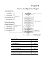
Chapter 6
Planning Your Application Program
Using this Chapter
If you want to read about
Go to page
DLL Driver
6-2
Command Structure
6-23
Modbus Function Code Introduction
6-24
Apply with ASCII Command
6-29
- System Command Set
6-35
- Analog Input Command Set
6-39
- Analog Input Alarm Command Set
6-56
- Digital I/O Command Set
6-66
6-1 Introduction
After completing the system configuration, you can begin to plan the application program. This chapter
introduces two programming tools for users to execute system data acquisition and control. The DLL
drivers and command sets provide a friendly interface between your applications and ADAM-6000 I/O
modules.
6-2 DLL (Dynamic Link Library) Driver
The Dynamic Link Library (DLL) enables you to quickly and easily to write Windows applications for
ADAM-6000 modules. The library supports Borland C, Delphi, Visual C++, and Visual Basic. Since
ADAM-6000 modules communicate with a host computer through Ethernet, no additional driver needs to
be installed. The DLL includes all necessary function calls to utilize the ADAM-6000 modules to their
fullest extent.
In the same path with “ADAM Ethernet I/O”, you‘ll find the relational example files for each kind of
programming languages after setup the Windows Utility program. You can customize the source code to
create your own tailor-made ADAM-6000 setup program or monitoring system.
6-2-1 Index
There are eight function libraries common used by ADAM-6000 and ADAM-5000/TCP list as follow:
ADAMTCP_Connect
ADAMTCP_Disconnection
ADAMTCP_GetDLLVersion
ADAMTCP_ReadReg
ADAMTCP_WriteReg
ADAMTCP_ReadCoil
ADAMTCP_WriteCoil
ADAMTCP_SendReceive5KTCPCmd
In addition, Advantech offers more function libraries especially for various ADAM-6000 applications.
ADAMTCP_SendReceive6KTCPCmd
ADAMTCP_Read6KDIO
ADAMTCP_Write6KDO
ADAMTCP_Read6KAI
ADAMTCP_Read6KDIOMode
ADAMTCP_Write6KDIOMode
ADAMTCP_Read6KSignalWidth
ADAMTCP_Write6KsignalWidth
ADAMTCP_Read6KCounter
ADAMTCP_Clear6KCounter
ADAMTCP_Start6KCounter
ADAMTCP_Stop6KCounter
ADAMTCP_Clear6KDILatch
6-2-2 Function Descriptions
ADAMTCP_Connect
Description:
Establish a Windows Sockets connection in a specified ADAM-6000 I/O module.
Syntax:
int ADAMTCP_Connect(int socket_type, char *szIP, unsigned short port, SOCKET *conn_socket,
int iConnectionTimeout, int iSendTimeout, int iReceiveTimeout);
Parameter:
socket_type[in]:
to specify the connection type that is UDP or TCP.
szIP[in]:
the IP address for ADAM-6000 that to be connected.
port[in]:
the connection port
conn_socket[out]:
iConnectionTimeout[in]:
iSendTimeout[in]:
iReceiveTimeout[in]:
the handle that represent a socket
the specified timeout interval for connecting to the ADAM-6000
the specified timeout interval for sending a command to the ADAM-6000
the specified timeout interval for receiving response from the ADAM-6000
Return:
Please refer to Chapter 6-2-3 “Return Codes” for more detail information
ADAMTCP_Disconnect
Description:
Disconnect the Windows Sockets connection of the specified ADAM-6000 I/O module.
Syntax:
void ADAMTCP_Disconnect(void);
Parameter:
void
Return:
Please refer to Chapter 6-2-3 “Return Codes” for more detail information
ADAMTCP_GetDLLVersion
Description:
Read the version of ADAM-6000 DLL driver
Syntax:
int ADAMTCP_GetDLLVersion(void);
Parameter:
void
Return:
0x100 -> Version 1.10
ADAMTCP_ReadReg
Description:
Read the holding register value at a specified range described in parameters.
Syntax:
int ADAMTCP_ReadReg(SOCKET conn_socket, WORD wStartAddress, WORD wCount, WORD
wData[ ])
Parameter:
conn_socket[in]:
the handle that represent the connection socket
wStartAddress[in]:
the starting address that to be read
wCount[in]:
how many holdings register to be read
wData[out]:
a unsigned 16 bits array that stored the read holding register
Return:
Please refer to Chapter 6-2-3 “Return Codes” for more detail information
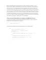
Example:
// Read input registers demo program
//--- In this demo program, reading 16 register starting at register 0(address 1)
//--- The IP address for ADAM-6000 module is 172.16.2.200 in this demo program.
//--- Change the IP Address to match your ADAM-6000 module
#include <windows.h>
#include <winsock2.h>
#include <stdlib.h>
#include <stdio.h>
#include <string.h>
#include "adv5ktcp.h"
#define DEFAULT_PORT 502
//-------- default timeout ----int
iConnectionTimeout=2000;
int
iSendTimeout=2000;
int
iReceiveTimeout=2000;
int main(int argc, char **argv)
{
int
i,j;
SOCKET conn_socket;
int
iRetVal,iVersion;
WORD
wStartAddress=1;
WORD
wCount=16;
WORD
wData[16];
char line[80];
printf("In this demo, the IP Address of 6000 module is assumed as 172.16.2.200\n");
printf("Please make sure the IP Address for your 6000 module is 172.16.2.200 (Y/N)? ");
gets(line);
if( toupper( line[0])!='Y' )
return 0;
for(i=0; i<wCount; i++)
wData[i]=0xffff;
iVersion=ADAMTCP_GetDLLVersion();
printf("The Version=%04x\n",iVersion);
//--- Firstly, try to create a connection to ADAM-6000 --//--- Please change the following IP address to match your ADAM-6000 module --iRetVal=ADAMTCP_Connect(SOCK_STREAM,"172.16.2.200",502,&conn_socket,
iConnectionTimeout, iSendTimeout, iReceiveTimeout);
if( iRetVal<0 )
{
printf("Connect Failure !!!
exit(0);
}
code=%d\n",iRetVal);
//--- reading input register --iRetVal=ADAMTCP_ReadReg(conn_socket, wStartAddress, wCount,wData);
if( iRetVal )
{
printf("ADAMTCP_ReadReg() Fail !!!
code=%d\n",iRetVal);
ADAMTCP_Disconnect();
exit(0);
}
for(i=0,j=wStartAddress; i<wCount; i++,j++)
{
printf("Addr:[%d] -> %04x\n",j,wData[i]);
}
printf("\n");
//--- Lastly, disconnection to 6000 I/O Modules --ADAMTCP_Disconnect();
printf("ADAMTCP_Discennect() successful !\n");
}
ADAMTCP_WriteReg
Description:
Write the holding register value at a specified range described in parameters.
Syntax:
int ADAMTCP_WriteReg(SOCKET conn_socket, WORD wStartAddress, WORD wCount, WORD
wData[ ])
Parameter:
conn_socket[in]:
the handle that represent the connection socket
wStartAddress[in]:
the starting address that to be read
wCount[in]:
how many holdings register to be read
wData[out]:
a unsigned 16 bits array that stored the value write to holding value
Return:
Please refer to Chapter 6-2-3 “Return Codes” for more detail information
ADAMTCP_ReadCoil
Description:
Read the coils value at a specified range described in parameters.
Syntax:
int ADAMTCP_ReadCoil(SOCKET conn_socket, WORD wStartAddress, WORD wCount, BYTE
byData[ ])
Parameter:
conn_socket[in]:
the handle that represent the connection socket
wStartAddress[in]:
the starting address that to be read
wCount[in]:
how many coils to be read
byData[out]:
a 8 bit array that stored the read coil
Return:
Please refer to Chapter 6-2-3 “Return Codes” for more detail information
ADAMTCP_WriteCoil
Description:
Write the coils value at a specified range described in parameters.
Syntax:
int ADAMTCP_WriteCoil(SOCKET conn_socket, WORD wStartAddress, WORD wCount, BYTE
byData[ ])
Parameter:
conn_socket[in]:
the handle that represent the connection socket
wStartAddress[in]:
the starting address that to be read
wCount[in]:
how many coils to be read
byData[out]:
a 8-bit array that stored the read coil
Return:
Please refer to Chapter 6-2-3 “Return Codes” for more detail information
ADAMTCP_SendReceive5KTCPCmd
Description:
This function is just for user's convenience, accepting the ASCII format string as a command. Then
transform it to meet the Modbus/TCP specification.
Syntax:
int ADAMTCP_SendReceive5KTCPCmd(SOCKET conn_socket, char szSendToTCP[ ], char
szReceiveFromTCP[ ], char szModbusSend[ ], char szModbusReceive[ ])
Parameter:
conn_socket[in]:
the handle that represent the connection socket
szSendToTCP[in]:
the ASCII format string that send to a ADAM-6000 module
szReceiveFromTCP[out]:
the ASCII format string that response from a ADAM-6000 module
szModbusSend[out]:
the Modbus/TCP format string that send to a ADAM-6000 module
szModbusReceive[out]:
the Modbus/TCP format string that response from a ADAM-6000 module
Return:
Please refer to Chapter 6-2-3 “Return Codes” for more detail information
ADAMTCP_SendReceive6KTCPCmd
Description:
This function is specific for 6000 series. It accepts the command in ASCII format string. Then transform
it to follow the Modbus/TCP communication protocol.
Syntax:
int ADAMTCP_SendReceive6KTCPCmd(char szIP[], char szSendToTCP[], char szReceiveFromTCP[]
char szModbusSend[], char szModbusReceive[])
Parameter:
szIP[in]:
szSendToTCP[in]:
the IP Address of the target ADAM-6000 module to be connected.
the ASCII format string that send to the ADAM-6000.
szReceiveFromTCP[out]:
the ASCII format string that response from the ADAM-6000.
szModbusSend[out]:
the Modbus/TCP format string that send to the ADAM-6000.
szModbusReceive[out]:
the Modbus/TCP format string that response from the ADAM-6000.
Return:
Please refer to Chapter 6-2-3 "Return Codes" for more detail information
ADAMTCP_Read6KDIO
Description:
To read the DI/DO status in the specific ADAM-6000 module.
Syntax:
int ADAMTCP_Read6KDIO(char szIP[], WORD wModule, WORD wIDAddr, BYTE byDI[], BYTE byDO[])
Parameter:
szIP[in]:
the IP Address of the target ADAM-6000 module to be connected.
wModule[in]:
the module name of the ADAM-6000 module to be connected.
(For example, 6050, 6051, or 6060)
wIDAddr[in]:
the Modbus device ID for an ADAM-6000 module. (Always 1)
byDI[out]:
an 8-bit array that stored the DI status of the specific ADAM-6000.
byDO[out]:
an 8-bit array that stored the DO status of the specific ADAM-6000.
Return:
Please refer to Chapter 6-2-3 "Return Codes" for more detail information.
ADAMTCP_Write6KDO
Description:
Set D/O status to an specific ADAM-6000 module.
Syntax:
int CALLBACK ADAMTCP_Write6KDO(char szIP[], WORD wModule, WORD wIDAddr, WORD
wStartDO, WORD wCount, BYTE byDO[])
Parameter:
szIP[in]:
the IP Address of the target ADAM-6000 module to be connected.
wModule[in]:
the module name of the ADAM-6000 module to be connected.
(For example, 6050, 6051, or 6060)
wIDAddr[in]:
the Modbus device ID for an ADAM-6000 module. (Always 1)
wStartDO[in]:
the starting channel to be written.
wCount[in]:
the total channels to be written.
byDO[out]:
an 8-bit array that stored the DO status of the specific ADAM-6000.
Return:
Please refer to Chapter 6-2-3 "Return Codes" for more detail information.
ADAMTCP_Read6KAI
Description:
To read analog input channel's value for an ADAM-6000 module.
Syntax:
int ADAMTCP_Read6KAI(char szIP[], WORD wModule, WORD wIDAddr, WORD wGain[], WORD
wHex[], double dlValue[])
Parameter:
szIP[in]:
the IP Address of the target ADAM-6000 module to be connected.
wModule[in]:
the module name of the ADAM-6000 module to be connected.
(For example, 6050, 6051, or 6060)
wIDAddr[in]:
wGain[in]:
the Modbus device ID for an ADAM-6000 module. (Always 1)
the range code against analog input range for individual channels stored in
this array.
wHex[out]:
an unsigned 16-bit array that stored the value reading from AI channels.
dlValue[out]:
an array that stored the values in engineer unit format that reading from AI
channels.
Return:
Please refer to Chapter 6-2-3 "Return Codes" for more detail information.
ADAMTCP_Read6KDIOMode
Description:
To read the working mode of each DI/O channels in a specific ADAM-6000 module.
Syntax:
int ADAMTCP_Read6KDIOMode(char szIP[], WORD wModule, WORD wIDAddr, BYTE byDIMode[],
BYTE byDOMode[])
Parameter:
szIP[in]:
the IP Address of the target ADAM-6000 module to be connected.
wModule[in]:
the module name of the ADAM-6000 module to be connected.
(For example, 6050, 6051, or 6060)
wIDAddr[in]:
the Modbus device ID for an ADAM-6000 module. (Always 1)
byDIMode[out]:
an 8-bit array that stored DI channels’ working modes which represent in
numeric format as follows:
0: this channel is in 'DI' mode
1: this channel is in 'Counter' mode
2: this channel is in 'Lo to Hi latch' mode
3: this channel is in 'Hi to Lo latch' mode
byDOMode[out]:
an 8-bits array that stored DO channels’ working modes which represent in
numeric format as follows:
0: this channel is in 'DO' mode
1: this channel is in 'Pulse Output' mode
2: this channel is in 'Lo to Hi Delay' mode
3: this channel is in 'Hi to Lo Delay' mode
Return:
Please refer to Chapter 6-2-3 "Return Codes" for more detail information.
ADAMTCP_Write6KDIOMode
Description:
To set the working modes for each DI/O channels in a specific ADAM-6000 module.
Syntax:
int ADAMTCP_Wirte6KDIOMode(char szIP[], WORD wModule, WORD wIDAddr, BYTE byDIMode[],
BYTE byDOMode[])
Parameter:
szIP[in]:
the IP Address of the target ADAM-6000 module to be connected.
wModule[in]:
the module name of the ADAM-6000 module to be connected.
(For example, 6050, 6051, or 6060)
wIDAddr[in]:
the Modbus device ID for an ADAM-6000 module. (Always 1)
byDIMode[in]:
an 8-bit array that stored DI channels’ working modes which represent in
numeric format as follows:
0: this channel is in 'DI' mode
1: this channel is in 'Counter' mode
2: this channel is in 'Lo to Hi latch' mode
3: this channel is in 'Hi to Lo latch' mode
byDOMode[in]:
an 8-bit array that stored D/O channels’ working modes which represent in
numeric format as follows:
0: this channel is in 'DO' mode
1: this channel is in 'Pulse Output' mode
2: this channel is in 'Lo to Hi Delay' mode
3: this channel is in 'Hi to Lo Delay' mode
Return:
Please refer to Chapter 6-2-3 "Return Codes" for more detail information.
ADAMTCP_Read6KSignalWidth
Description:
To read the minimal high/low signal width of each D/I channel in a specific ADAM-6000 module.
Syntax:
int ADAMTCP_Read6KSignalWidth(char szIP[], WORD wModule, WORD wIDAddr, unsigned long
ulLoWidth[], unsigned long ulHiWidth[])
Parameter:
szIP[in]:
the IP Address of the target ADAM-6000 module to be connected.
wModule[in]:
the module name of the ADAM-6000 module to be connected.
(For example, 6050, 6051, or 6060)
wIDAddr[in]:
the Modbus device ID for an ADAM-6000 module. (Always 1)
ulLoWidth[out]:
an unsigned 32-bit array that stored the minimal low signal width of each DI
channel. The unit is 0.1 msec.
ulHiWidth[out]:
an unsigned 32-bit array that stored the minimal high signal width of each DI
channel. The unit is 0.1 msec.
Return:
Please refer to Chapter 6-2-3 "Return Codes" for more detail information.
ADAMTCP_Write6KSignalWidth
Description:
To set the minimal high/low signal width of each DI channel in a specific ADAM-6000 module.
Syntax:
int ADAMTCP_Write6KSignalWidth(char szIP[], WORD wModule, WORD wIDAddr, unsigned long
ulLoWidth[], unsigned long ulHiWidth[])
Parameter:
szIP[in]:
the IP Address of the target ADAM-6000 module to be connected.
wModule[in]:
the module name of the ADAM-6000 module to be connected.
(For example, 6050, 6051, or 6060)
wIDAddr[in]:
the Modbus device ID for an ADAM-6000 module. (Always 1)
ulLoWidth[out]:
an unsigned 32-bit array that stored the minimal low signal width of each DI
channel. The unit is 0.1 msec.
ulHiWidth[out]:
an unsigned 32-bit array that stored the minimal high signal width of each DI
channel. The unit is 0.1 msec.
Return:
Please refer to Chapter 6-2-3 "Return Codes" for more detail information.
ADAMTCP_Read6KCounter
Description:
To read the counter value when a DI channel configured in 'Counter' mode.
Syntax:
int ADAMTCP_Read6KCounter(char szIP[], WORD wModule, WORD wIDAddr,
unsigned long ulCounterValue[]);
Parameter:
szIP[in]:
the IP Address of the target ADAM-6000 module to be connected.
wModule[in]:
the module name of the ADAM-6000 module to be connected.
(For example, 6050, 6051, or 6060)
wIDAddr[in]:
the Modbus device ID for an ADAM-6000 module. (Always 1)
ulCounterValue[out]:
an unsigned 32-bit array that stored the counter value of each DI channel.
Return:
Please refer to Chapter 6-2-3 "Return Codes" for more detail information.
ADAMTCP_Clear6KCounter
Description:
To clear the counter value when a DI channel configured in 'Counter' mode.
Syntax:
int ADAMTCP_Clear6KCounter(char szIP[], WORD wIDAdd, WORD wChIndex, WORD wData)
Parameter:
szIP[in]:
the IP Address of the target ADAM-6000 module to be connected.
wIDAddr[in]:
the Modbus device ID for an ADAM-6000 module. (Always 1)
wChIndex[in]:
the specific DI channel need to be cleared the counter value.
wData[in]:
always 1.
Return:
Please refer to Chapter 6-2-3 "Return Codes" for more detail information.
ADAMTCP_Start6KCounter
Description:
Start counting when a DI channel configured as 'Counter' mode.
Syntax:
int ADAMTCP_Start6KCounter(char szIP[], WORD wAddress, WORD wChIndex)
Parameter:
szIP[in]:
the IP Address of the target ADAM-6000 module to be connected.
wIDAddr[in]:
the Modbus device ID for an ADAM-6000 module. (Always 1)
wChIndex[in]:
the specific DI channel need to start or stop counting.
Return:
Please refer to Chapter 6-2-3 "Return Codes" for more detail information.
ADAMTCP_Stop6KCounter
Description:
Stop counting when a DI channel configured as 'Counter' mode.
Syntax:
int ADAMTCP_Stop6KCounter(char szIP[], WORD wAddress, WORD wChIndex)
Parameter:
szIP[in]:
the IP Address of the target ADAM-6000 module to be connected.
wIDAddr[in]:
the Modbus device ID for an ADAM-6000 module. (Always 1)
wChIndex[in]:
the specific DI channel need to start or stop counting.
Return:
Please refer to Chapter 6-2-3 "Return Codes" for more detail information.
ADAMTCP_Clear6KDILatch
Description:
To clear the latch when a DI channel configured as 'Lo to Hi Latch' or 'Hi to Lo Latch'.
Syntax:
int ADAMTCP_Clear6KDILatch(char szIP[], WORD wIDAddr, WORD wChIndex)
Parameter:
szIP[in]:
the IP Address of the target ADAM-6000 module to be connected.
wIDAddr[in]:
the Modbus device ID for an ADAM-6000 module. (Always 1)
wChIndex[in]:
the specific DI channel need to be cleared the latch status.
Return:
Please refer to Chapter 6-2-3 "Return Codes" for more detail information.
6-2-3 Return Codes
Using these function libraries, you can read the error message from the returning codes.
ADAM5KTCP_NoError
(0)
ADAM5KTCP_StartupFailure
(-1)
ADAM5KTCP_SocketFailure
(-2)
ADAM5KTCP_UdpSocketFailure
(-3)
ADAM5KTCP_SetTimeoutFailure
(-4)
ADAM5KTCP_SendFailure
(-5)
ADAM5KTCP_ReceiveFailure
(-6)
ADAM5KTCP_ExceedMaxFailure
(-7)
ADAM5KTCP_CreateWsaEventFailure
(-8)
ADAM5KTCP_ReadStreamDataFailure
(-9)
ADAM5KTCP_InvalidIP
(-10)
ADAM5KTCP_ThisIPNotConnected
(-11)
ADAM5KTCP_AlarmInfoEmpty
(-12)
ADAM5KTCP_NotSupportModule
(-13)
ADAM5KTCP_ExceedDONo
(-14)
ADAM5KTCP_InvalidRange
(-15)
6-3 ADAM-6000 Commands
ADAM-6000 and ADAM-5000/TCP system accept a command/response form with the host computer.
When systems are not transmitting they are in listen mode. The host issues a command to a system
with a specified address and waits a certain amount of time for the system to respond. If no response
arrives, a time-out aborts the sequence and returns control to the host. This chapter explains the
structure of the commands with Modbus/TCP protocol, and guides to use these command sets to
implement user’s programs.
6-3-1 Command Structure
It is important to understand the encapsulation of a Modbus request or response carried on the
Modbus/TCP network. A complete command is consisted of command head and command body. The
command head is prefixed by six bytes and responded to pack Modbus format; the command body
defines target device and requested action. Following example will help you to realize this structure
quickly.
Example:
If you want to read the first two values of ADAM-6017 (address: 40001~40002), the request command
should be:
Figure 6-1 Request Comment Structure
And the response should be:
Figure 6-2 Response Comment Structure
6-3-2 Modbus Function Code Introductions
To full-fill the programming requirement, there is a series of function code standard for user’s
reference…
Code (Hex)
01
02
03
04
05
06
08
15
16
Name
Usage
Read Coil Status
Read Discrete Output Bit
Read Input Status
Read Discrete Input Bit
Read Holding Registers Read 16-bit register. Used to read integer
or floating point process data.
Read Input Registers
Force Single Coil
Write data to force coil ON/OFF
Preset Single Register
Write data in 16-bit integer format
Loopback Diagnosis
Diagnostic testing of the communication port
Force Multiple Coils
Write multiple data to force coil ON/OFF
Preset Multiple Registers Write multiple data in 16-bit integer format
Table 6-1 Response Comment Structure
Function Code 01
The function code 01 is used to read the discrete output’s ON/OFF status of ADAM-6000 modules in a
binary data format.
Request message format for function code 01:
Command Body
Station Function Start Address Start Address Requested Number Requested Number
Address Code
High Byte
Low Byte of Coil High Byte of Coil Low Byte
Example: Read coil number 1 to 8 (address number 00017 to 00024) from ADAM-6000 Modules
01 01 00 17 00 08
Response message format for function code 01:
Command Body
Station Function
Address
Code
Byte
Count
Data
Data
…
Example: Coils number 2 and 7 are on, all others are off.
01 01 01 42
In the response the status of coils 1 to 8 is shown as the byte value 42 hex, equal to 0100 0010
binary.
Function Code 02
The function code 02 is used to read the discrete input’s ON/OFF status of ADAM-6000 in a binary data
format.
Request message format for function code 02:
Command Body
Station Function Start Address Start Address Requested Number Requested Number
Address Code
High Byte
Low Byte of Input High Byte of Input Low Byte
Example: Read coil number 1 to 8 (address number 00001 to 00008) from ADAM-6000 modules
01 01 00 01 00 08
Response message format for function code 02:
Command Body
Station Function
Address
Code
Byte
Count
Data
Data
…
Example: input number 2 and 3 are on, all others are off.
01 01 01 60
In the response the status of input 1 to 8 is shown as the byte value 60 hex, equal to 0110 0000
binary.
Function Code 03/04
The function code 03 or 04 is used to read the binary contents of input registers
Request message format for function code 03 or 04:
Command Body
Station Function Start Address Start Address Requested Number Requested Number
Address Code
High Byte
Low Byte of Register High Byte of Register Low Byte
Example: Read Analog inputs #1 and #2 in addresses 40001 to 40002 as floating point value from
ADAM-6017 module
01 04 00 01 00 02
Response message format for function code 03 or 04:
Command Body
Station Function
Address Code
Byte
Count
Data
Data
…
Example: Analog input #1 and #2 as floating point values where AI#1=100.0 and AI#2=55.32
01 04 08 42 C8 00 00 47 AE 42 5D
Function Code 05
Force a single coil to either ON or OFF. The requested ON/OFF state is specified by a constant in the
query data field. A value of FF 00 hex requests it to be ON. A value of 00 00 hex requests it to be OFF.
And a value of FF FF hex requests it to release the force.
Request message format for function code 05:
Command Body
Station Function Coil Address
Address
Code
High Byte
Coil Address
Low Byte
Force Data
High Byte
Force Data
Low Byte
Example: Force coil 3 (address 00003) ON in ADAM-6000 module
01 05 00 03 FF 00
Response message format for function code 05:
The normal response is an echo of the query, returned after the coil state has been forced.
Command Body
Station Function Coil Address
Address
Code
High Byte
Coil Address
Low Byte
Force Data
High Byte
Force Data
Low Byte
Function Code 06
Presets integer value into a single register.
Request message format for function code 06:
Command Body
Station Function Register Address Register Address Preset Data Preset Data
Address
Code
High Byte
Low Byte
High Byte Low Byte
Example: Preset register 40002 to 00 04 hex in ADAM-6000 module
01 06 00 02 00 04
Response message format for function code 06:
The normal response is an echo of the query, returned after the coil state has been preset.
Command Body
Station Function Register Address Register Address Preset Data Preset Data
Address
Code
High Byte
Low Byte
High Byte Low Byte
Function Code 08
Echoes received query message. Message can be any length up to half the length of the data buffer
minus 8 bytes.
Request message format for function code 08:
Command Body
Station Function Any data, length limited to approximately half the
Address Code
length of the data buffer
Example: 01 08 00 02 00 04
Response message format for function code 08:
Command Body
Station Function
Address Code
Data bytes received
Example: 01 08 00 02 00 04
Function Code 15 (0F hex)
Forces each coil in a sequence of coils to either ON or OFF.
Request message format for function code 15:
Command Body
Station Function Start Address Start Address Requested Number Requested Number Byte Force Data Force Data
Address Code
High Byte
Low Byte
of Coil High Byte of Coil Low Byte
Count High Byte Low Byte
Example: Request to force a series of 10 coils starting at address 00017 (11 hex) in ADAM-6000
module.
01 0F 00 11 00 0A 02 CD 01
The query data contents are two bytes: CD 01 hex, equal to 1100 1101 0000 0001 binary. The
binary bits are mapped to the addresses in the following way.
Bit:
1 1 0 0 1 1 0 1
0 0 0 0 0 0 0 1
Address (000XX): 24 23 22 21 20 19 18 17
-
-
-
-
-
-
26 25
Response message format for function code 08:
The normal responses return the station address, function code, start address, and requested number of
coil forced.
Command Body
Station Function Start Address Start Address Requested Number Requested Number
Address Code
High Byte
Low Byte of Coil High Byte of Coil Low Byte
Example: 01 0F 00 11 00 0A
Function Code 16 (10 hex)
Preset values into a sequence of holding registers.
Request message format for function code 16:
Command Body
Station Function Start Address Start Address
Address Code
High Byte
Low Byte
Requested Number Requested Number
Byte Data
of Register High Byte of Register Low Byte Count
Example: Preset constant #1 (address 40009) to 100.0 in ADAM-6000 module.
01 10 00 09 00 02 04 42 C8 00 00
Response message format for function code 08:
The normal responses return the station address, function code, start address, and requested number of
registers preset.
Command Body
Station Function Start Address Start Address Requested Number Requested Number
Address Code
High Byte Low Byte of Register High Byte of Register Low Byte
Example: 01 10 00 09 00 02
6-4 Apply with ASCII Command for ADAM-6000 Modules
For users do not familiar to Modbus protocol, Advantech offers a function library as a protocol translator,
integrating ASCII command into Modbus/TCP structure. Therefore, users familiar to ASCII command
can access ADAM-6000 easily. Before explaining the structure of ASCII command packed with
Modbus/TCP format. Let’s see how to use an ASCII command and how many commands are available
for your program.
TCP Format Modbus Format ASCII Command
Figure 6-3 ASCII Command Structure in ADAM-6000
6-4-1 Syntax of ASCII
Command Syntax:
[delimiter character][address][slot][channel][command][data][checksum][carriage return]
Every command begins with a delimiter character. There are two valid characters:
$ and #
The delimiter character is followed by a two-character address (hex-decimal) that specifies the target
system. The two characters following the address specified the module and channel.
Depending on the command, an optional data segment may follow the command string. An optional twocharacter checksum may also be appended to the command string. Every command is terminated with
a carriage return (cr).
Note: All commands should be issued in UPPERCASE characters only!
The command set is divided into the following three categories:
System Command Set
· Analog Input Command Set
Analog Input Alarm Command Set
· Digital I/O Modules Command Set
Every command set category starts with a command summary of the particular type of module, followed
by datasheets that give detailed information about individual commands.
Although commands in different subsections sometime share the same format, the effect they have on a
certain module can be completely different than that of another. Therefore, the full command sets for
each type of modules are listed along with a description of the effect the command has on the given
module.
6-4-2 I/O Module Command Set Searching Tables
ADAM-6017 Command Table
Command
Syntax
$aaAff
$aaB
$aaAnntt
$aaBnn
#aan
#aa
$aa0
$aa1
$aa6
$aa5mm
Command Name
Description
Set Integration Time Sets the integration time for a
specified module
Get Integration Time Get the integration time from a
specified module
Set Input Range
Set the input range to the specified
channel in the analog input module
Read Input Range
Read the input range of the specified
channel in the analog input module
Read Analog Input Return the input value from the
from Channel N
specified channel in the analog input
module
Read Analog Input Return the input values from all
from all channels
channels of the specified analog
input module
Span Calibration
Calibrate the analog input module to
correct the gain error
Offset Calibration
Calibrate the analog input module to
correct the offset error
Read Channels Status Asks a specified input module to
return the status of all channels
Enable/Disable
Enables/Disables multiplexing
multiplexing
simultaneously for separate channels
of the specified input module
#aaMH
#aaMHn
#aaML
#aaMLn
$aaEmm
$aaE
#aaDnd
$aaCjAhs
$aaCjAh
$aaCjAhEs
$aaCjCh
$aaCjAhCCn
$aaCjRhC
$aaCjAhU
$aaCjRhU
$aaCjS
$aaF
$aaM
Read all Max. Data
Read the maximum data from all
channels in the specified module
Read single Max.
Read the maximum date from a
Data
specified channel in the module
Read all Min. Data Read the minimum data from all
channels in the specified module
Read single Min.
Read the minimum data from a
Data
specified channel in the module
Enable/Disable
Enables/Disables the specified
Channels to Average channels for data average function
Read Ave. Channels Identify which channels are included
in average function
Set Digital Output
Set the status of the specified digital
output in the ADAM-6017 module
Set Alarm Mode
Set the High/Low alarm in either
Momentary or Latching mode
Read Alarm Mode
Returns the alarm mode for the
specified channels
Enable/Disable AlarmEnables/Disables the high/low alarm
of the specified channels
Clear Latch Alarm Resets a latched alarm
Set Alarm
Connection
Connects the High/Low alarm of a
specified input channel to interlock
with a specified output channel
Read Alarm
Returns the alarm configuration of a
Connection
specified input channel
Set Alarm Limit
Set the High/Low alarm limit value
to a specified channel
Read Alarm Limit
Returns the High/Low alarm limit
value of the specified channel
Read Alarm Status Reads whether an alarm occurred in
the specified channel
Read Firmware
Return the firmware version code
Version
from the specified ADAM-6000
module.
Read Module Name Return the module name from the
specified module
ADAM-6050 Command Table
Command
Syntax
$aaAff
$aa6
#aabb
$aa5
$aaF
$aaM
Command Name
Description
Configuration
Sets the integration time for a
specified module
Read Channels Status Asks a specified input module to
return the status of all channels
Write Digital Output Writes specified values to either a
single channel or all channels
simultaneously
Reset Status
Indicates whether a specified digital
I/O module was reset after the last
time the $aa5 command was issued
Read Firmware
Return the firmware version code
Version
from the specified ADAM-6000
module.
Read Module Name Return the module name from the
specified module
ADAM-6051 Command Table
Command
Syntax
$aaAff
$aa6
#aabb
$aa5
$aaF
$aaM
Command Name
Description
Configuration
Sets the integration time for a
specified module
Read Channels Status Asks a specified input module to
return the status of all channels
Write Digital Output Writes specified values to either a
single channel or all channels
simultaneously
Reset Status
Indicates whether a specified digital
I/O module was reset after the last
time the $aa5 command was issued
Read Firmware
Return the firmware version code
Version
from the specified ADAM-6000
module.
Read Module Name Return the module name from the
specified module
ADAM-6060 Command Table
Command
Syntax
$aaAff
$aa6
#aabb
$aa5
$aaF
$aaM
Command Name
Description
Configuration
Sets the integration time for a
specified module
Read Channels Status Asks a specified input module to
return the status of all channels
Write Digital Output Writes specified values to either a
single channel or all channels
simultaneously
Reset Status
Indicates whether a specified digital
I/O module was reset after the last
time the $aa5 command was issued
Read Firmware
Return the firmware version code
Version
from the specified ADAM-6000
module.
Read Module Name Return the module name from the
specified module
6-4-3 System Command Set
$aaAff
Name
Set Integration Time
Description
Sets an integration time to a specified ADAM-6000 module.
Syntax
$aaAff(cr)
$ is a delimiter character.
aa (range 00-FF) represents the 2-character hexadecimal Modbus address
of the ADAM-6000 module you want to configure. (Always 01)
A is I/O module configuration command.
ff represents the integration time.
50
means 50ms (Operation Under 60 Hz power)
60
means 60ms (Operation Under 50 Hz power)
(cr) is the terminating character, carriage return (0Dh)
Response
!aa(cr) if the command is valid.
?aa(cr) if an invalid operation was entered.
There is no response if the module detects a syntax error or communication
error or if the specified address does not exist.
! delimiter character indicating a valid command was received.
? delimiter character indicating the command was invalid.
aa (range 00-FF) represents the 2-character hexadecimal address of an
ADAM-6000 module.
(cr) is the terminating character, carriage return (0Dh)
Example
command: $01A50(cr)
response: !01(cr)
The ADAM-6000 module at address 01h is configured to an integration time
50ms (60Hz). The response indicates that the command has been received.
Note: An analog input module requires a maximum of 7 seconds to perform auto calibration
and ranging after it is reconfigured. During this time span, the module cannot be addressed to
perform any other actions.
$aaB
Name
Read Integration Time Setting
Description
Read the integration time setting of a specified ADAM-6000 module.
Syntax
$aaB(cr)
$ is a delimiter character.
aa (range 00-FF) represents the 2-character hexadecimal Modbus address
of the ADAM-6000 module you want to configure. (Always 01)
B is I/O module configuration reading command.
51
means 50ms (Operation Under 60 Hz power)
60
means 60ms (Operation Under 50 Hz power)
(cr) is the terminating character, carriage return (0Dh)
Response
!aaff(cr) if the command is valid.
?aa(cr) if an invalid operation was entered.
There is no response if the module detects a syntax error or communication
error or if the specified address does not exist.
! delimiter character indicating a valid command was received.
? delimiter character indicating the command was invalid.
aa (range 00-FF) represents the 2-character hexadecimal address of an
ADAM-6000 module.
ff represents the integration time.
50
means 50ms (Operation Under 60 Hz power)
60
means 60ms (Operation Under 50 Hz power)
(cr) is the terminating character, carriage return (0Dh)
Example
command: $01B(cr)
response: !0150(cr)
The ADAM-6000 module at address 01h is configured to an integration time
50ms (60Hz).
$aaM
Name
Description
Syntax
Read Module Name
Returns the module name from a specified ADAM-6000 module.
$aaM(cr)
$ is a delimiter character.
aa (range 00-FF) represents the 2-character hexadecimal Modbus address
of the ADAM-6000 module you want to interrogate. (Always 01)
M is the Module Name command.
(cr) is the terminating character, carriage return (0Dh).
Response
!aa60bb(cr) if the command is valid.
?aa(cr) if an invalid operation was entered.
There is no response if the module detects a syntax error, communication
error or if the specified address does not exist.
! delimiter character indicating a valid command was received.
? delimiter character indicating the command was in-valid.
aa (range 00-FF) represents the 2-character hexadecimal address of an
ADAM-6000 module.
bb (range 00-FF) represents the 2-character model number of an
ADAM-6000 module.
(cr) is the terminating character, carriage return (0Dh).
Example
command: $01M(cr)
response: !0150(cr)
The command requests the system at address 01h to send its module name.
The system at address 01h responds with module name 6050 indicating that
there is an ADAM-6050 at address 01h.
$aaF
Name
Read Firmware Version
Description
Syntax
Returns the firmware version code from a specified ADAM-6000 module.
$aaF(cr)
$ is a delimiter character.
aa (range 00-FF) represents the 2-character hexadecimal Modbus address
of the ADAM-6000 module you want to interrogate. (Always 01)
F is the Firmware Version command.
(cr) is the terminating character, carriage return (0Dh).
Response
!aa(version)(cr) if the command is valid.
?aa(cr) if an invalid operation was entered.
There is no response if the module detects a syntax error, communication
error or if the specified address does not exist.
! delimiter character indicating a valid command was received.
? delimiter character indicating the command was invalid.
aa (range 00-FF) represents the 2-character hexadecimal address of an
ADAM-6000 module.
(version) represents the firmware version of the ADAM-6000 module.
(cr) is the terminating character, carriage return (0Dh).
Example
command: $01F(cr)
response: !01A1.01(cr)
The command requests the system at address 01h to send its firmware version.
The system responds with firmware version A1.01.
6-4-4 Analog Input Command Set
Command
Syntax
$aaAnntt
$aaBnn
#aan
#aa
$aa0
$aa1
$aa6
$aa5mm
#aaMH
#aaMHn
#aaML
#aaMLn
$aaEmm
$aaE
#aaDnd
$aaAnntt
Command Name
Description
Set Input Range
Set the input range to the specified
channel in the analog input module
Read Input Range
Read the input range of the specified
channel in the analog input module
Read Analog Input Return the input value from the
from Channel N
specified channel in the analog input
module
Read Analog Input Return the input values from all
from all channels
channels of the specified analog
input module
Span Calibration
Calibrate the analog input module to
correct the gain error
Offset Calibration
Calibrate the analog input module to
correct the offset error
Read Channels Status Asks a specified input module to
return the status of all channels
Enable/Disable
Enables/Disables multiplexing
multiplexing
simultaneously for separate channels
of the specified input module
Read all Max. Data Read the maximum data from all
channels in the specified module
Read single Max.
Read the maximum date from a
Data
specified channel in the module
Read all Min. Data Read the minimum data from all
channels in the specified module
Read single Min.
Read the minimum data from a
Data
specified channel in the module
Enable/Disable
Enables/Disables the specified
Channels to Average channels for data average function
Read Ave. Channels Identify which channels are included
in average function
Set Digital Output
Set the status of the specified digital
output in the ADAM-6017 module
Name
Set Input Range
Description
Sets the input range for a specified channel of a specified analog input
module.
Syntax
$aaAnntt
$ is a delimiter character.
aa (range 00-FF) represents the 2-character hexadecimal Modbus address
of the ADAM-6000 module you want to configure. (Always 01)
A represents the set input range command.
nn (range 00-07) represents the specific channel you want to set the input
range.
tt (range 0x07-0x0D) represents the 2-character code of the input type.
(Refer to the table below)
(cr) is the terminating character, carriage return (0Dh).
Signal Type and Range Against Code
4 ~ 20mA
07
-10V ~ 10V
08
0V ~ 5V
09
-1V ~ 1V
0A
0mV ~ 500mV
0B
-100mV ~ 100mV
0C
0 ~ 20mA
0D
Table 6-4 ADAM-6017 Analog Input Range mapping Table
Response
!aa(cr) if the command is valid.
?aa(cr) if an invalid operation was entered.
There is no response if the module detects a syntax error or communication
error or if the specified address does not exist.
! delimiter character indicating a valid command was received.
? delimiter character indicating the command was invalid.
aa (range 00-FF) represents the 2-character hexadecimal Modbus address of
an ADAM-6000 module.
(cr) is the terminating character, carriage return (0Dh).
Example
command: $01A0107(cr)
response: !01(cr)
Channel 1 of the ADAM-6017 module at address 01h is set to the input range
4-20 mA. The response indicates that the command has been received as a
valid command.
$aaBnn
Name
Description
Read Input Range
Returns the input range for a specified channel of a specified analog input
module.
Syntax
$aaBnn
$ is a delimiter character.
aa (range 00-FF) represents the 2-character hexadecimal Modbus address
of the ADAM-6000 module you want to interrogate. (Always 01)
B represents the read input range command.
nn (range 00-07) represents the specific channel you want to read the input
range.
(cr) is the terminating character, carriage return (0Dh).
Response
!aatt(cr) if the command is valid.
?aa(cr) if an invalid operation was entered.
There is no response if the module detects a syntax error or communication
error or if the specified address does not exist.
! delimiter character indicating a valid command was received.
? delimiter character indicating the command was invalid.
aa (range 00-FF) represents the 2-character hexadecimal Modbus address of
an ADAM-6000 module.
tt (range 0x07-0x0D) represents the 2-character code of the input type.
(Refer to the Table 6-4)
(cr) is the terminating character, carriage return (0Dh).
Example
command: $01B01(cr)
response: !0107(cr)
Channel 1 of the ADAM-6017 module at address 01h responds with an input
range 4-20 mA.
$aan
Name
Description
Read Analog Input from Channel N
Returns the input data from a specified channel in a specified analog input
module.
Syntax
$aan
$ is a delimiter character.
aa (range 00-FF) represents the 2-character hexadecimal Modbus address
of the ADAM-6000 module you want to interrogate. (Always 01)
n (range 0-8) represents the specific channel you want to read the input
data.
(cr) is the terminating character, carriage return (0Dh).
Response
>(data)(cr) if the command is valid.
?aa(cr) if an invalid operation was entered.
There is no response if the module detects a syntax error or communication
error or if the specified address does not exist.
! delimiter character indicating a valid command was received.
? delimiter character indicating the command was invalid.
(cr) is the terminating character, carriage return (0Dh).
Example
command: $012(cr)
response: >+10.000
Channel 2 of the ADAM-6017 module at address 01h responds with an input
value +10.000.
$aa
Name
Description
Syntax
Read Analog Input from All Channels
Returns the input data from all channels in a specified analog input module.
$aa
$ is a delimiter character.
aa (range 00-FF) represents the 2-character hexadecimal Modbus address
of the ADAM-6000 module you want to interrogate. (Always 01)
(cr) is the terminating character, carriage return (0Dh).
Response
>(data)(data)(data)(data)(data)(data)(data)(data)(data)(cr) if the command
is valid.
?aa(cr) if an invalid operation was entered.
There is no response if the module detects a syntax error or communication
error or if the specified address does not exist.
! delimiter character indicating a valid command was received.
? delimiter character indicating the command was invalid.
(cr) is the terminating character, carriage return (0Dh).
Note: The latest data returned is the Average value of the preset channels in this module.
Example
command: $01(cr)
response:
>+10.000+10.000+10.000+10.000+10.000+10.000+10.000+10.000+10.000
$aa0
Name
Description
Syntax
Span Calibration
Calibrates a specified analog input module to correct for gain errors
$aa0(cr)
$ is a delimiter character.
aa (range 00-FF) represents the 2-character hexadecimal Modbus address
of the ADAM-6000 module which is to be calibrated. (Always 01)
0 represents the span calibration command.
(cr) is the terminating character, carriage return (0Dh)
Response
!aa(cr) if the command is valid.
?aa(cr) if an invalid operation was entered.
There is no response if the module detects a syntax error or communication
error or if the specified address does not exist.
! delimiter character indicating a valid command was received.
? delimiter character indicating the command was invalid.
aa (range 00-FF) represents the 2-character hexadecimal Modbus address of
an ADAM-6000 module.
(cr) is the terminating character, carriage return (0Dh)
Note: In order to successfully calibrate an analog input module's input range,
a proper calibration input signal should be connected to the analog input
module before and during the calibration process.
$aa1
Name
Description
Syntax
Zero Calibration
Calibrates a specified analog input module to correct for offset errors
$aa1(cr)
$ is a delimiter character.
aa (range 00-FF) represents the 2-character hexadecimal Modbus address
of the ADAM-6000 module which is to be calibrated. (Always 01)
1 represents the zero calibration command.
(cr) is the terminating character, carriage return (0Dh)
Response
!aa(cr) if the command is valid.
?aa(cr) if an invalid operation was entered.
There is no response if the module detects a syntax error or communication
error or if the specified address does not exist.
! delimiter character indicating a valid command was received.
? delimiter character indicating the command was invalid.
aa (range 00-FF) represents the 2-character hexadecimal Modbus address of
an ADAM-6000 module.
(cr) is the terminating character, carriage return (0Dh)
Note: In order to successfully calibrate an analog input module's input range, a proper
calibration input signal should be connected to the analog input module before and during the
calibration process.
$aa6
Name
Read Channels Status
Description
Syntax
Asks a specified input module to return the status of all channels
$aa6(cr)
$ is a delimiter character.
aa (range 00-FF) represents the 2-character hexadecimal Modbus address
of the ADAM-6000 module you want to interrogate. (Always 01)
6 is the read channels status command.
(cr) is the terminating character, carriage return (0Dh)
Response
!aamm(cr) if the command is valid.
?aa(cr) if an invalid operation was entered.
There is no response if the module detects a syntax error or communication
error or if the specified address does not exist.
! delimiter character indicating a valid command was received.
? delimiter character indicating the command was invalid.
aa (range 00-FF) represents the 2-character hexadecimal Modbus address of
an ADAM-6000 module.
mm are two hexadecimal values. Each value is interpreted as 4 bits. The first
4-bit value represents the status of channels 4-7, the second 4 bits
represents the status of channels 0-3. A value of 0 means the channel is
disabled, while a value of 1 means the channel is enabled.
(cr) is the terminating character, carriage return (0Dh)
Example
command: $016(cr)
response: !01FF(cr)
The command asks the analog input module in slot 1 of the system at address
01h to send the status of its input channels. The analog input module responds
that all its multiplex channels are enabling (FF equals 1111 and 1111).
$aa5mm
Name
Description
Enable/Disable Channels for multiplexing
Enables/Disables multiplexing for separate channels of the specified input
module
Syntax
$aa5mm(cr)
$ is a delimiter character.
aa (range 00-FF) represents the 2-character hexadecimal Modbus address
of the ADAM-6000 module. (Always 01)
5 identifies the enable/disable channels command.
mm (range 00-FF) are two hexadecimal characters. Each character is
interpreted as 4 bits. The first 4-bit value represents the status of channels
4-7; the second 4-bit value represents the status of channels 0-3. A value of
0 means the channel is disabled, while a value of 1 means the channel is
enabled.
(cr) is the terminating character, carriage return (0Dh)
Response
!aa(cr) if the command is valid.
?aa(cr) if an invalid operation was entered.
There is no response if the module detects a syntax error or communication
error or if the specified address does not exist.
! delimiter character indicating a valid command was received.
? delimiter character indicating the command was invalid.
aa (range 00-FF) represents the 2-character hexadecimal Modbus address of
an ADAM-6000 module.
(cr) is the terminating character, carriage return (0Dh)
Example
command: $01581(cr)
response: !01(cr)
The command enables/disables channels of the analog input module at
address 01h. Hexadecimal 8 equals binary 1000, which enables channel 7
and disables channels 4, 5 and 6. Hexadecimal 1 equals binary 0001, which
enables channel 0 and disables channels 1, 2 and 3.
#aaMH
Name
Description
Read Maximum Value
Read the Maximum values from all channels in a specified analog input
module
Syntax
$aaMH(cr)
$ is a delimiter character.
aa (range 00-FF) represents the 2-character hexadecimal Modbus address
of the ADAM-6000 module to be read. (Always 01)
MH represents the read maximum value command.
(cr) is the terminating character, carriage return (0Dh)
Response
>(data)…(cr) if the command is valid.
?aa(cr) if an invalid operation was entered.
There is no response if the module detects a syntax error or communication
error or if the specified address does not exist.
! delimiter character indicating a valid command was received.
? delimiter character indicating the command was invalid.
aa (range 00-FF) represents the 2-character hexadecimal Modbus address of
an ADAM-6000 module.
(cr) is the terminating character, carriage return (0Dh)
Example
command: $01MH(cr)
response:
>+10.000+10.000+10.000+10.000+10.000+10.000+10.000+10.000+10.000
Note: The latest data returned is the Average value of the preset channels in this module.
#aaMHn
Name
Read Maximum Value from channel N
Description
Read the Maximum values from a specific channel in a specified analog
input module
Syntax
$aaMHn(cr)
$ is a delimiter character.
aa (range 00-FF) represents the 2-character hexadecimal Modbus address
of the ADAM-6000 module to be read. (Always 01)
MH represents the read maximum value command.
n (range 0-8) represents the specific channel you want to read the input
data.
Note: The latest data returned is the Average value of the preset channels in this
module.
(cr) is the terminating character, carriage return (0Dh)
Response
>(data)(cr) if the command is valid.
?aa(cr) if an invalid operation was entered.
There is no response if the module detects a syntax error or communication
error or if the specified address does not exist.
! delimiter character indicating a valid command was received.
? delimiter character indicating the command was invalid.
aa (range 00-FF) represents the 2-character hexadecimal Modbus address of
an ADAM-6000 module.
(cr) is the terminating character, carriage return (0Dh)
Example
command: $01MH2(cr)
response: >+10.000
#aaML
Name
Description
Read Minimum Value
Read the Minimum values from all channels in a specified analog input
module
Syntax
$aaML(cr)
$ is a delimiter character.
aa (range 00-FF) represents the 2-character hexadecimal Modbus address
of the ADAM-6000 module to be read. (Always 01)
ML represents the read minimum value command.
(cr) is the terminating character, carriage return (0Dh)
Response
>(data)…(cr) if the command is valid.
?aa(cr) if an invalid operation was entered.
There is no response if the module detects a syntax error or communication
error or if the specified address does not exist.
! delimiter character indicating a valid command was received.
? delimiter character indicating the command was invalid.
aa (range 00-FF) represents the 2-character hexadecimal Modbus address of
an ADAM-6000 module.
(cr) is the terminating character, carriage return (0Dh)
Example
command: $01ML(cr)
response:
>+10.000+10.000+10.000+10.000+10.000+10.000+10.000+10.000+10.000
Note: The latest data returned is the Average value of the preset channels in this module.
#aaMLn
Name
Read Minimum Value from channel N
Description
Read the Minimum values from a specific channel in a specified analog input
module
Syntax
$aaMLn(cr)
$ is a delimiter character.
aa (range 00-FF) represents the 2-character hexadecimal Modbus address
of the ADAM-6000 module to be read. (Always 01)
ML represents the read minimum value command.
n (range 0-8) represents the specific channel you want to read the input
data.
Note: The latest data returned is the Average value of the preset channels in this
module.
(cr) is the terminating character, carriage return (0Dh)
Response
>(data)(cr) if the command is valid.
?aa(cr) if an invalid operation was entered.
There is no response if the module detects a syntax error or communication
error or if the specified address does not exist.
! delimiter character indicating a valid command was received.
? delimiter character indicating the command was invalid.
aa (range 00-FF) represents the 2-character hexadecimal Modbus address of
an ADAM-6000 module.
(cr) is the terminating character, carriage return (0Dh)
Example
command: $01ML3(cr)
response: >+10.000
#aaEmm
Name
Description
Enable/Disable Channels for Average
Enables/Disables the specific channels in the analog input module for the
average function.
Syntax
$aaEmm(cr)
$ is a delimiter character.
aa (range 00-FF) represents the 2-character hexadecimal Modbus address
of the ADAM-6000 module to be read. (Always 01)
E represents the enable/disable channel for average command.
mm (range 00-FF) are two hexadecimal characters. Each character is
interpreted as 4 bits. The first 4-bit value represents the status of channels
4-7; the second 4-bit value represents the status of channels 0-3. A value of
0 means the channel is disabled, while a value of 1 means the channel is
enabled.
(cr) is the terminating character, carriage return (0Dh)
Response
!aa(cr) if the command is valid.
?aa(cr) if an invalid operation was entered.
There is no response if the module detects a syntax error or communication
error or if the specified address does not exist.
! delimiter character indicating a valid command was received.
? delimiter character indicating the command was invalid.
aa (range 00-FF) represents the 2-character hexadecimal Modbus address of
an ADAM-6000 module.
(cr) is the terminating character, carriage return (0Dh)
Example
command: $01E03(cr)
response: !01
The command enables/disables channels for average function in the analog
input module at address 01h. Hexadecimal 03 equals binary 00000011,
which enables channel 0, 1 and disables the rest of other channels.
#aaE
Name
Description
Read the Average Enable/Disable Status
Read the average enable/disable status of all channels in the specific analog
input module.
Syntax
$aaE(cr)
$ is a delimiter character.
aa (range 00-FF) represents the 2-character hexadecimal Modbus address
of the ADAM-6000 module to be read. (Always 01)
E represents the enable/disable channel for average command.
(cr) is the terminating character, carriage return (0Dh)
Response
!aamm(cr) if the command is valid.
?aa(cr) if an invalid operation was entered.
There is no response if the module detects a syntax error or communication
error or if the specified address does not exist.
! delimiter character indicating a valid command was received.
? delimiter character indicating the command was invalid.
aa (range 00-FF) represents the 2-character hexadecimal Modbus address of
an ADAM-6000 module.
mm (range 00-FF) are two hexadecimal characters. Each character is
interpreted as 4 bits. The first 4-bit value represents the status of channels
4-7; the second 4-bit value represents the status of channels 0-3. A value of
0 means the channel is disabled, while a value of 1 means the channel is
enabled.
(cr) is the terminating character, carriage return (0Dh)
Example
command: $01E(cr)
response: !0103
The command set “ON” status to the channel 0 in the analog input module at
address 01h.
#aaDnd
Name
Description
Syntax
Set Digital Output
Set the digital output status in ADAM-6000 analog input module.
$aaDnd(cr)
$ is a delimiter character.
aa (range 00-FF) represents the 2-character hexadecimal Modbus address
of the ADAM-6000 module to be read. (Always 01)
D represents the digital output setting command.
n (range 0-1) represents the specific channel you want to set the output
status.
d (range 0-1) represents the status you want to set to the specific channel
(cr) is the terminating character, carriage return (0Dh)
Response
!aa(cr) if the command is valid.
?aa(cr) if an invalid operation was entered.
There is no response if the module detects a syntax error or communication
error or if the specified address does not exist.
! delimiter character indicating a valid command was received.
? delimiter character indicating the command was invalid.
aa (range 00-FF) represents the 2-character hexadecimal Modbus address of
an ADAM-6000 module.
(cr) is the terminating character, carriage return (0Dh)
Example
command: $01D01(cr)
response: !01
The command set “ON” status to the channel 0 in the analog input module at
address 01h.
6-4-5 Analog Input Alarm Command Set
$aaCjAhs
$aaCjAh
$aaCjAhEs
$aaCjCh
Set Alarm Mode
Set the High/Low alarm in either
Momentary or Latching mode
Read Alarm Mode
Returns the alarm mode for the
specified channels
Enable/Disable AlarmEnables/Disables the high/low alarm
of the specified channels
Clear Latch Alarm Resets a latched alarm
$aaCjAhCCn
Set Alarm
Connection
$aaCjRhC
$aaCjAhU
Read Alarm
Connection
Set Alarm Limit
$aaCjRhU
Read Alarm Limit
$aaCjS
Read Alarm Status
$aaCjAhs
Connects the High/Low alarm of a
specified input channel to interlock
with a specified output channel
Returns the alarm configuration of a
specified input channel
Set the High/Low alarm limit value
to a specified channel
Returns the High/Low alarm limit
value of the specified channel
Reads whether an alarm occurred in
the specified channel
Name
Description
Set Alarm Mode
Sets the High/Low alarm of the specified input channel in the addressed ADAM-6000
module to either Latching or Momentary mode.
Syntax
$aaCjAhs(cr)
$ is a delimiter character.
aa (range 00-FF) represents the 2-character hexadecimal Modbus network address of an
ADAM-6000 module. (Always 01)
Cj identifies the desired channel j (j : 0 to 7).
A is the Set Alarm Mode command.
h indicates alarm types (H = High alarm, L = Low alarm)
s indicates alarm modes (M = Momentary mode, L = Latching mode)
(cr) represents terminating character, carriage return (0Dh)
Response
!aa(cr) if the command was valid
?aa(cr) if an invalid operation was entered.
There is no response if the system detects a syntax error or communication error or if
the specified address does not exist.
! delimiter character indicating a valid command was received.
aa represents the 2-character hexadecimal address of the corresponding ADAM-6000
module.
(cr) represents terminating character, carriage return (0Dh)
Example
command: $01C1AHL(cr)
response: !01(cr)
Channel 1 of the ADAM-6000 module at address 01h is instructed to set its High alarm in
Latching mode.
The module confirms that the command has been received.
$aaCjAh
Name
Read Alarm Mode
Description
Returns the alarm mode for the specified channel in the specified ADAM-6000
module.
Syntax
$aaCjAh(cr)
$ is a delimiter character.
aa (range 00-FF) represents the 2-character hexadecimal Modbus network address of an
ADAM-6000 module. (Always 01)
Cj identifies the desired channel j (j : 0 to 7).
A is the Read Alarm Mode command.
h indicates the alarm types (H = High alarm, L = Low alarm)
(cr) represents terminating character, carriage return (0Dh)
Response
!aas(cr) if the command was valid
?aa(cr) if an invalid operation was entered.
There is no response if the system detects a syntax error or communication error or if
the specified address does not exist.
! delimiter character indicating a valid command was received.
aa represents the 2-character hexadecimal address of the corresponding ADAM-6000
module.
s indicates alarm modes (M = Momentary mode, L = Latching mode)
(cr) represents terminating character, carriage return (0Dh)
Example
command: $01C1AL(cr)
response: !01M(cr)
Channel 1 of the ADAM-6000 module at address 01h is instructed to return its Low alarm
mode.
The system responds that it is in Momentary mode.
$aaCjAhEs
Name
Description
Enable/Disable Alarm
Enables/Disables the High/Low alarm of the specified input channel in the addressed
ADAM-6000 module
Syntax
$aaCjAhEs(cr)
$ is a delimiter character.
aa (range 00-FF) represents the 2-character hexadecimal Modbus network address of an
ADAM-6000 module. (Always 01)
Cj identifies the desired channel j (j : 0 to 7).
AhEs is the Set Alarm Mode command.
h indicates alarm type (H = High alarm, L = Low alarm)
s indicates alarm enable/disable (E = Enable, D = Disable)
(cr) represents terminating character, carriage return (0Dh)
Response
!aa(cr) if the command was valid
?aa(cr) if an invalid operation was entered.
There is no response if the system detects a syntax error or communication error or if
the specified address does not exist.
! delimiter character indicating a valid command was received.
aa represents the 2-character hexadecimal address of the corresponding ADAM-6000
module.
(cr) represents terminating character, carriage return (0Dh)
Example
command: $01C1ALEE(cr)
response: !01(cr)
Channel 1 of the ADAM-6000 module at address 01h is instructed to enable its
Low alarm function.
The module confirms that its Low alarm function has been enabled.
Note:
An analog input module requires a maximum of 2 seconds after it receives an
Enable/Disable Alarm command to let the setting take effect. During this interval, the
module cannot be addressed to perform any other actions.
$aaCjCh
Name
Description
Clear Latch Alarm
Sets the High/Low alarm to OFF (no alarm) for the specified input channel in the
addressed ADAM-6000 module
Syntax
$aaCjCh(cr)
$ is a delimiter character.
aa (range 00-FF) represents the 2-character hexadecimal Modbus network address of an
ADAM-6000 module. (Always 01)
Cj identifies the desired channel j (j : 0 to 7).
Ch is the Clear Latch Alarm command.
h indicates alarm type (H = High alarm, L = Low alarm)
(cr) represents terminating character, carriage return (0Dh)
Response
!aa(cr) if the command was valid
?aa(cr) if an invalid operation was entered.
There is no response if the system detects a syntax error or communication error or if
the specified address does not exist.
! delimiter character indicating a valid command was received.
aa represents the 2-character hexadecimal Modbus network address of the corresponding
ADAM-6000 module.
(cr) represents terminating character, carriage return (0Dh)
Example
command: $01C1CL(cr)
response: !01(cr)
Channel 1 of the ADAM-6000 module at address 01h is instructed to set its Low alarm
state to OFF.
The system confirms it has done so accordingly.
$aaCjAhCCn
Name
Set Alarm Connection
Description
Connects the High/Low alarm of the specified input channel to interlock the specified
digital output in the addressed ADAM-6000 module
Syntax
$aaCjAhCCn(cr)
$ is a delimiter character.
aa (range 00-FF) represents the 2-character hexadecimal Modbus network address of an
ADAM-6000/TCP module. (Always 01)
Cj identifies the desired analog input channel j (j : 0 to 7).
AhC is the Set Alarm Connection command.
h indicates alarm type (H = High alarm, L = Low alarm)
Cn identifies the desired digital output channel n (n : 0 to 1). To disconnect the digital
output, n should be set as ‘*’.
(cr) represents terminating character, carriage return (0Dh)
Response
!aa(cr) if the command was valid
?aa(cr) if an invalid operation was entered.
There is no response if the system detects a syntax error or communication error
or if the specified address does not exist.
! delimiter character indicating a valid command was received.
aa represents the 2-character hexadecimal Modbus network address of the corresponding
ADAM-6000 module.
(cr) represents terminating character, carriage return (0Dh)
Example
command: $01C1ALCC0(cr)
response: !01(cr)
Channel 1 of the ADAM-6000 module at address 01h is instructed to connect its Low alarm
to the digital output of channel 0 in the specific ADAM-6000 module.
The system confirms it has done so accordingly.
$aaCjRhC
Name
Read Alarm Connection
Description
Returns the High/Low alarm limit output connection of a specified input channel in the
addressed ADAM-6000 module
Syntax
$aaCjRhC(cr)
$ is a delimiter character.
aa (range 00-FF) represents the 2-character hexadecimal Modbus address of an
ADAM-6000 module. (Always 01)
Cj identifies the desired analog input channel j (j : 0 to 7).
RhC is the Read Alarm Connection command.
h indicates alarm type (H = High alarm, L = Low alarm)
(cr) represents terminating character, carriage return (0Dh)
Response
!aaCn(cr) if the command was valid
?aa(cr) if an invalid operation was entered.
There is no response if the system detects a syntax error or communication error
or if the specified address does not exist.
! delimiter character indicating a valid command was received.
aa represents the 2-character hexadecimal Modbus network address of the corresponding
ADAM-6000 module.
Cn identifies the desired digital output channel n (n : 0 to 1) whether interlock with the
alarm of the specific analog input channel. If the values of n are ‘*’, the analog input has no
connection with a digital output point.
(cr) represents terminating character, carriage return (0Dh)
Example
command: $01C1RLC(cr)
response: !01C0(cr)
Channel 1 of the ADAM-6000 module at address 01h is instructed to read its Low alarm
output connection.
The system responds that the Low alarm output connects to the digital output at channel 0
in the specific ADAM-6000 module.
$aaCjAhU
Name
Set Alarm Limit
Description
Sets the High/Low alarm limit value for the specified input channel of a specified
ADAM-6000 module.
Syntax
$aaCjAhU(data)(cr)
$ is a delimiter character.
aa (range 00-FF) represents the 2-character hexadecimal Modbus network address of an
ADAM-6000 module. (Always 01)
Cj identifies the desired analog input channel j (j : 0 to 7).
AhU is the Set Alarm Limit command.
h indicates alarm type (H = High alarm, L = Low alarm)
(data) represents the desired alarm limit setting. The format is always in engineering units.
(cr) represents terminating character, carriage return (0Dh)
Response
!aa(cr) if the command was valid
?aa(cr) if an invalid operation was entered.
There is no response if the system detects a syntax error or communication error or if the
specified address does not exist.
! delimiter character indicating a valid command was received.
aa represents the 2-character hexadecimal Modbus network address of the corresponding
ADAM-6000 module.
(cr) represents terminating character, carriage return (0Dh)
Example
command: $01C1AHU+080.00(cr)
response: !01(cr)
The high alarm limit of the channel 1 in the specific ADAM-6000 module at address 01h is
been set +80.
The system confirms the command has been received.
Note:
An analog input module requires a maximum of 2 seconds after it receives a Set
Alarm Limit command to let the settings take effect. During this interval, the module cannot
be addressed to perform any other actions.
$aaCjRhU
Name
Read Alarm Limit
Description
Returns the High/Low alarm limit value for the specified input channel in the
addressed ADAM-6000 module
Syntax
$aaCjRhU(cr)
$ is a delimiter character.
aa (range 00-FF) represents the 2-character hexadecimal Modbus network address of an
ADAM-6000 module. (Always 01)
Cj identifies the desired analog input channel j (j : 0 to 7).
RhU is the Read Alarm Limit command.
h indicates alarm type (H = High alarm, L = Low alarm)
(cr) represents terminating character, carriage return (0Dh)
Response
!aa(data)(cr) if the command was valid
?aa(cr) if an invalid operation was entered.
There is no response if the system detects a syntax error or communication error or if the
specified address does not exist.
! delimiter character indicating a valid command was received.
aa represents the 2-character hexadecimal Modbus network address of the corresponding
ADAM-6000 module.
(data) represents the desired alarm limit setting. The format is always in engineering units.
(cr) represents terminating character, carriage return (0Dh)
Example
command: $01C1RHU(cr)
response: !01+2.0500(cr)
Channel 1 of the ADAM-6000 module at address 01h is configured to accept 5V input. The
command instructs the system to return the High alarm limit value for that channel.
The system responds that the High alarm limit value in the desired channel is 2.0500 V.
$aaCjS
Name
Description
Read Alarm Status
Reads whether an alarm occurred to the specified input channel in the specified
ADAM-6000 module
Syntax
$aaCjS(cr)
$ is a delimiter character.
aa (range 00-FF) represents the 2-character hexadecimal Modbus network address of an
ADAM-6000 module. (Always 01)
Cj identifies the desired analog input channel j (j : 0 to 7).
S is the Read Alarm Status command.
(cr) represents terminating character, carriage return (0Dh)
Response
!aahl(cr) if the command was valid
?aa(cr) if an invalid operation was entered.
There is no response if the system detects a syntax error or communication error or if the
specified address does not exist.
! delimiter character indicating a valid command was received.
aa represents the 2-character hexadecimal address Modbus of the corresponding
ADAM-6000 module.
h represents the status of High alarm. ‘1’ means the High alarm occurred, ‘0’ means it did
not occur.
l represents the status of Low alarm. ‘1’ means the Low alarm occurred, ‘0’ means it did
not occur.
(cr) represents terminating character, carriage return (0Dh)
Example
command: $01C1S(cr)
response: !0101(cr)
The command asks the module at address 01h to return its alarm status for channel 1.
The system responds that a High alarm has not occurred, but the Low alarm has occurred.
6-4-6 Digital Input/Output Command Set
Command
Syntax
$aa6
Command Name
Description
Read Channels Status Asks a specified input module to
return the status of all channels
#aabb
Write Digital Output Writes specified values to either a
single channel or all channels
simultaneously
$aa6
Name
Description
Read Channel Status
This command requests that the specified ADAM-6000 module return the status of its
digital input channels and a read-back value of its digital output channels.
Syntax
$aa6(cr)
$ is a delimiter character.
aa (range 00-FF) represents the 2-character hexadecimal Modbus network address of the
ADAM-6000 module. (Always 01)
6 is the Digital Data In command.
(cr) is the terminating character, carriage return (0Dh)
Response
!aa(data)(data)00(cr) if the command is valid. (ADAM-6050/6051/6060)
?aa(cr) if an invalid operation was entered.
There is no response if the module detects a syntax error or communication error or if
the specified address does not exist.
! delimiter character indicating a valid command was received.
? delimiter character indicating the command was invalid.
aa (range 00-FF) represents the 2-character hexadecimal Modbus network address of
an ADAM-6000 module.
(data) a 2-character hexadecimal value representing the values of the digital input
module.
(cr) is the terminating character, carriage return (0Dh)
Example
command: $016(cr)
response: !01112200(cr)
The command asks the specific ADAM-6000 module at address 01h to return the
values of all channels.
The first 2-character portion of the response indicates the address of the ADAM-6000
module. The second 2-character portion of the response, value 11h (00010001),
indicates that digital input channels 8 and 12 are ‘ON’, channels 9, 10, 11, 13, 14 and
15 are ‘OFF’. The third 2-character portion of the response, value 22h (00100010),
indicates that digital input channels 1 and 5 are ON, and channels 0, 2, 3, 4, 6 and 7
are OFF.
#aabb(data)
Name
Description
Write Digital Output
This command sets a single or all digital output channels to the specific ADAM-6000
module.
Syntax
#aabb(data)(cr)
# is a delimiter character.
aa (range 00-FF) represents the 2-character hexadecimal Modbus network address of
the ADAM-6000 module. (Always 01)
bb is used to indicate which channel(s) you want to set.
Writing to all channels (write a byte): both characters should be equal to zero (BB=00).
Writing to a single channel (write a bit): first character is 1, second character indicates
channel number which can range from 0h to Fh.
(data) is the hexadecimal representation of the digital output value(s).
When writing to a single channel (bit) the first character is always 0. The value of
the second character is either 0 or 1.
When writing to all channels (byte) 2 or 4-characters are significant. The digital
equivalent of these hexadecimal characters represent the channels' values.
Response
>(cr) if the command was valid.
?aa(cr) if an invalid command has been issued.
There is no response if the module detects a syntax error or communication error or if
the specified address does not exist.
> delimiter character indicating a valid command was received.
? delimiter character indicating the command was invalid.
aa (range 00-FF) represents the 2-character hexadecimal Modbus network address of
an ADAM-6000 module that is responding.
(cr) is the terminating character, carriage return (0Dh)
Example
command: #151201(cr)
response: >(cr)
An output bit with value 1 is sent to channel 2 of a digital output module at
address 01h. Channel 2 of the digital output module is set to ‘ON’.
command: #010012(cr)
response: >(cr)
An output byte with value 12h (00010010) is sent to the digital output module
at address 01h. Channels 1and 4 will be set to ‘ON’, and all other channels
will be set to ‘OFF’.
Note:
If any channel of the digital output module is configured as the output for an analog
input alarm, it cannot be reconfigured via digital output commands. Channels used for
analog input alarms always have a higher priority.
Appendix A
Design Worksheets
An organized system configuration will lead to efficient performance and reduce engineer effort. This Appendix
provides the necessary worksheet, helping users to configure their DA&C system in order. Follow these working steps
to build up your system relational document:
Step 1. Asking questions and getting answers for your control strategy.
1) What will be monitored and controlled? (List the equipment)
2) What will be monitored and controlled separately? (Divide the function area)
3) What will be monitored and controlled by ADAM-6000 I/O? (List the target equipment in different function areas)
Step 2. Identify the I/O types of each equipment and full-fill Table A-1 to establish the I/O data base.
Function Equipment Input or I/O Module I/O Module Voltage of Current of
Special
Area
Output
Type
Product No. Range
Range Requirements
Table A-1 I/O Data Base
Step 3. Mapping the I/O data base into ADAM-6000 I/O modules.
1) In column A, note the ADAM-6000/TCP IP addresses mapped for individual function areas.
2) In column B, list the I/O module’s product number.
3) In column C, enter the maximum number of I/O points available per module.
4) In column D, total the number of the I/O point you need.
5) In column E, calculate the total number of these modules that you will need.
6) In column F, enter the number of spare modules that you may need for future expansion in your systems.
7) In column G, enter the total number (Required + Spare) of these modules that you need for these systems.
<A>
<B>
<C>
<D>
<E>
<F>
<G>
ADAM-6000 I/O Module I/O Points Total I/O Points I/O Module
Spare
Total
IP Address Product No. per Module
Required
Required I/O Modules I/O Modules
Table A-2 Summary Required Modules
Step 4. Implement the Modbus address in to the I/O table.
ADAM-6000
IP Address
I/O Type
Channel
I/O
Number Address
Tag Name
Equipment &
Description
Table A-3 Table for Programming
These several worksheets are very useful to hardware wiring and software integration, please make copies to establish
your own system configuration documentation.