1
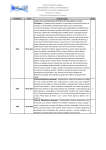
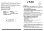
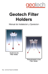
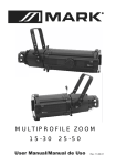
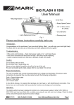
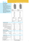
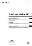
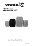
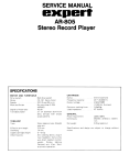
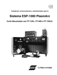
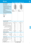
MULTIPAR 575/2
User Manual / Instrucciones de Usuario
V. 2
MULTIPAR 575/2
English Version ............... Page 1
Version Español .............. Página 5
MULTIPAR 575/2
Yoke
Yoke locking knob
Lamp
housing
Retaining clip
Lens catcher
Lens
Colour frame
Spring clip
Lens rotation ring
Colour frame holder
Tabs
IMPORTANT SAFETY INSTRUCTIONS
1. Before you initially start-up, please make sure that there is no damage caused by transportation. Should there be any,
consult your dealer and do not use the device.
2. CAUTION! Be careful with your operations. With a dangerous voltage you can suffer a dangerous electric shock when
touching the wires! Keep away from heaters and other heating sources!
3. Do not mount the device on or near combustible sufaces. Do not operate the device without a lens installed.
4. Always hang the device with the color frame retaining clip in the locked position.
5. This device falls under protection-class I, therefore it is essential that the yellow/green conductor gets connected to
earth. The electric connection must be carried out by a qualified employee.
6. Make sure that the power-cord is never crimped or damaged by sharp edges. Check the device and the power-cord
from time to time.
8. If the external flexible cable or cord of this luminaire is damaged, it shall be exclusively replaced by the manufacturer or
his service agent or a similar qualified person in order to avoid a hazard.
9. Shields, lenses or ultraviolet screens shall be changed if they have become visibly damaged to such an extent that
their effectiveness is impaired, for example by cracks or deep scratches.
10. Never let the power-cord come into contact with other cables! Handle the power-cord and all connections with the
mains with particular caution!
11. Always disconnect from the mains, when the device is not in use or before cleaning it. Only handle the power-cord by
the plug. Never pull out the plug by tugging the power-cord.
12. During the initial start-up some smoke or smell may arise. This is a normal process and does not necessarily mean
that the device is defective.
13. DANGER OF BURNING! Never touch the device during the operation! The housing heats up to the housing
temperature T
.
14. Don't switch the device on and off in short intervals as this would reduce the lamp's life.
15. HEAL
TH HAZARD! Never look directly into the light source, as sensitive persons may suffer an epileptic shock
(especially meant for epileptics)!
16. Keep away children and amateurs from the device!
17. There are no serviceable parts inside the device. Maintenance and service operations are only to be carried out by
authorized dealers.
SURFACE
Accessories
Color frame
Very Narrow Spot lens
Narrow Spot lens
Medium Flood lens
Wide Flood lens
407CF
400-VNSP
400-NSP
400-MFL
400-WFL
-1-
MULTIPAR 575/2
Retaining clip in
the locked position
Color frame retaining clip
The color frame holder is equipped with a spring-loaded retaining clip that prevents color
frames and accessories from falling out.
WARNING! Hang the MUL TI PAR with the color frame retaining clip in the locked position.
1.Release the retaining clip by pushing it sideways. The retaining clip opens.
2.lnsert the color frame.
3.Press the retaining clip down until it locks.
Note: Use only color frames or top hats with 6.7-inch inside diameter.
Figure 1
Cleaning the reflector
The following recommendations are offered when cleaning and inspecting lenses and reflectors:
Do not use glass and window cleaners on the reflector. Chemicals in these cleaners will harm the reflective coating.
Do not use paper towels or harsh materials to wipe the reflector. These materials can scratch the surface of the reflector.
WARNING! Unplug the fixture before attempting to clean reflector .
1.Remove the lens so you can access the reflector from the front of the fixture. See Removing a lens on page 2
2.Remove dust with a blast of oil free air, or wipe with a clean, soft, lint-free cotton cloth. lf this is sufficient to remove
dust, go to step 5. Otherwise, continue to step 3.
3.Dampen a clean, soft, lint-free cotton cloth with a mild, soapy water solution and gently wipe the reflector.
4.Remove any soapy water residue with a clean, soft, lint-free cotton cloth dampened with water.
5.Reinstall a lens before using the fixture.
Installing the GKV Iamp
Always replace the lamp if it becomes damaged or deformed.
Verify that the GKV lamp you use is suitable for the voltage at your facility. 115,
120, 230, and 240 volt GKV lamps are available.
Caution! Operating lamps above their rated voltage reduces lamp life and can
cause premature lamp failure .
1.Disconnect the unit from power before installing the lamp.
WARNING! Let lamp cool before changing .
HPL lamp
Lamp brackets
2.Loosen the knurled bolt on the back of the lamp housing and pull the housing
straight out from the back of the fixture.
3.Remove the GKV lamp from its box,holding it by the base.
Note: To avoid premature lamp failure , do not touch the lamp glass with your
fingers. If you touch the lamp during installation, clean it carefully with
rubbing alcohol and a clean, lint -free cloth before operation .
Knurled bolt
4.Line up the flat sides of the lamp base with the brackets on either side of the
Lamp housing
socket (Figure 2).
5.Push down on the lamp base until the lamp is firmly seated. Make sure that the
Figure 2
lamp is fully seated, with the bottom of the lamp heat sink flush to the lamp housing casting.
Caution! lmproperly installed lamps cause premature lamp failure and socket problems .
6.To reinstall the lamp housing, center it on the reflector and the bolt hole, then tighten the knurled bolt to secure the
lamp housing in place.
Lens identification
Lenses for the MULTI PAR come in four versions. The type or beam spread can be identified by the lens texture.
MFL
WFL
VNSP
NSP
Very narrow spot
Clear glass
15º Round beam shape
Narrow spot
Stipple glass
19º Round beam shape
Medium flood
Fewer facets,sized 6x22mm
21º x34º Oblong beam shape
-2-
Wide flood
Many facets,sized 6x12mm
30º x51º Oblong beam shape
MULTIPAR 575/2
Changing MUL TI PAR lenses
Change lenses if they become cracked or badly scratched.Caution! Never operate the MUL TI P AR without a lens in place.
Installing a lens
1.Position the fixture with the front of the unit (the lens side) facing you, and tilted slightly(Figure 4)
2.Position the lens rotation ring with the spring clip at the top of the fixture, directly below the
retaining clip.
3.Hold the lens by the edge, and position it so the convex side faces the back of the fixture(Figure 3) .
Note: Installing the lens with the convex side out will not impair the optics,but it will make
Retaining clip
Spring clip
removing the lens dificult.
4.From the top of the fixture, slide the lens behind the lens catchers and position its base behind the
tabs on the bottom of the lens rotation ring.
5.Gently push the top of the lens inward until it snaps behind the spring clip.
Tab
Figure 3
Spring clip
Removing a lens
WARNING! Uuplug the fixture before attempting to remove or install a lens.
1.Source MULTI PAR lenses get hot while the unit is in operation.Let the fixture cool before
handling the lens.
2.Place the fixture on a flat, stable work surface. Do not install or remove lenses with the unit
hanging.
3.Position the lens rotation ring with the spring clip at the top of the unit, directly below the
retaining clip.
4.Tilt the front of the fixture down at least 45º .
5.Press the spring clip with your finger to release the lens(Figure 4 ).
6.Allow the lens to drop forward from under the clip.
7.When the lens drops,remove your finger, allowing the lens to slide forward until it rests on the
lens catchers (Figure 5 ) .
8.Carefully remove the lens from the fixture.
Tab
Retaining clip
Figure 4
Lens
catcher
Figure 5
Selecting a Mounting Location
The fixture should be installed outside areas where persons may walk by or be seated.
1. Before rigging make sure that the installation area can hold a minimum point load of 10 times the fixture's weight.
2. Do not install the fixture on radiant-heating type area
3. Out of the way but within arm's reach, so you can operate it easily
4. Close enough to an AC outlet to use the attached power cord
5. When installing the device, make sure there is no highly inflammable material (decoration articles, etc.) within a distance
of min. 1.0M
6. For overhead use, always install a safety-rope that can hold at least 10 times the weight of the fixture. You must only
use safety-ropes with screw-on carabines.
Warning: To reduce the likelihood of the injury or damage to person, mount it only on a stable and sturdy area.
Installation With Clamp
Clamp
Safty Rope
You can choose a appropriate clamp from your dealer to fix the fixture
Carabine
to the mounting pipe(e.g.truss system), and adjust the position of the
Safty Screw
fixture once it is mounted.(Figure 6)
1. Tightly fasten the clamp to the yoke with the provided yoke bolt and
Safty Hole
lock washer.
2. Place the clamp on mounting pipe, then tighten the pipe bolt to secure it.
3. Loosen the clamp pan screw and rotate the yoke to the desired position.
4. Tighten the pan screw to lock the fixture into position.
5. Adjust the desired inclination-angle via the yoke and fix the Yoke locking knob.
6. Pull the safety-rope through the hole on the housing and over the mounting
pipe etc. Insert the end in the carabine and tighten the safety screw.
-3-
pipe (of truss)
Pan screw
Pipe bolt
Yoke bolt
Yoke
Yoke locking
knob.
Figure 6
MULTIPAR 575/2
Installing /Connection with the mains
1. DANGER O
T LIFE! The electric connection must only be carried out by a qualified electrician!
2. In order to connect the device to the mains, you have to install a power-plug.
3. The occupation of the connection-cables is as follows:
Cable
Brown
Blue
Yellow/Green
Pin
Live
Neutral
Earth
International
L
N
4. The earth has to be connected!
5. Connect the device to the mains with the power-plug.
6. If the device will be directly connected with the local power supply network, a disconnection switch with a minimum
opening of 3 mm at every pole has to be included in the permanent electrical installation.
7. In general, lighting effects should not be connected to dimming-packs.
8. DANGER O
T LIFE! Before taking into operation for the first time, the installation has to be approved by an expert!
OPERA
TION:
After you connected the spot to the mains, you can control the sports via your lighting controller.
GKV Iamps
Use the GKV lamp only in MULTI PAR
TECHNICAL
SPECIFICATIONS
Lamp type:
Power consumption
Dimensions (L x W x H);
Weight;
Fitting lamp
Maximum ambient temperature ta:
Maximum housing temperature tS:
Minimum distance:
GKV 600
Max. 600W
250 x 250 x 350mm
1.4 kg
GKV lamps Base: GX9.5 Halogen
25° C
160° C
2m
-4-
MULTIPAR 575/2
MULTIPAR 575/2
Asa
Sujección del asa
Clip de retención
Sujección de lente
Portalámparas
Lente
Portafiltro
Sujección
Anillo de rotación
Sujección Portafiltro
Topes
IMPORT ANTES INSTRUCCIONES DE SEGURIDAD
1. Antes de encender la unidad, compruebe que no han habido daños en el transporte, en caso de haberlos, contacte
con su distribuidor.
2. PRECAUCION Sea cuidadoso con su manipulación, pude sufrir descargas eléctricas si toca los cables, manténgalo
apartado de fuentes de calor.
3. No monte el dispositivo cerca de fuentes inflamables. NO opere con la unidad sin las lentes instaladas.
4. Coloque siempre el dispositivo con el portafiltros bien sujeto con el clip.
5. Este dispositivo está bajo protección I, así es esencial que el conductor amarillo/verde, sea conectado a tierra. La
conexión debe ser realizada por una persona cualificada.
6. Asegúrese de que el cable no está pisado o dañado. Compruebe el dispositivo y el cable regularmente.
7. Si es cable externo se daña, debe ser sustituido sólo por el suministrado por el fabricante y siempre por un técnico
cualificado.
8. Filtros, lentes o pantallas ultravioletas, deben ser sustituidas si parecen seriamente dañadas para no reducir su eficacia.
9. Nunca deje que el cable de red entre en contacto con otros cables, Manipule el cable y sus conexiones con
especial cuidado.
10. Desconecte la red si no va a usar el dispositivo o va a limpiarlo. Manipule el cable cogiendo el enchufe, nunca lo
estire para su desconexión.
11. Durante el encendido inicial, puede aparecer algo de humo u olor, es un proceso normal y no significa necesariamente
que funcione mal.
12. PELIGRO DE QUEMADURA Nunca toque el dispositivo durante su funcionamiento, el calor en el recinto es muy
elevado.
13. No encienda o apague la unidad en cortos intervalos, reduce la vida de las lámparas.
14. PELIGRO A LA SALUD Nunca mire directamente a la luz, las personas sensibles, pueden sufrir ataques epilépticos.
15. Mantenga a los niños apartados del dispositivo.
16. No hay partes ajustables en el interior. El mantenimiento y reparación sólo deben ser realizados por personal
cualificado.
Accesorios
Filtro Color
Lente haz muy estrecho
Lente haz estrecho
Lente dispersión media
Lente dispersión ancha
407CF
400-VNSP
400-NSP
400-MFL
400-WFL
-5-
MULTIPAR 575/2
Enganche de retención
En la posición de bloqueo
Clip de sujección del portafiltros de colores
El hueco del portafiltros, está equipado con un enganche para prevenir que el filtro o los accesorios
puedan caer.
ATENCION! Cuelge el MULTIPAR con el portafiltros fijado con el clip
1.Libere el clip de retención del portafiltros presionándolo, el clip se abre.
2.lnserte el portafiltros de colores.
3.Presione el clip hasta fijar el portafiltros.
Nota: Use sólo portafiltros con 6 o 7 pulgadas de diámetro interno.
Figura 1
Limpiando el reflector
Las siguientes recomendaciones, se ofrecen para limpiar y revisar las lentes y reflectores.
No use limpiadores de cristales o ventanes en el reflector. Pueden dañar la cubierta reflectora.
No use toallas de papel para limpiar el el reflector. Pueden rayar la superficie del reflector.
ATENCION! Desconecte la unidad antes de limpiar el reflector .
1.Retire la lente si quiere llegar al reflector por la parte delantera. Vea la sección Quitar la lente en página 7.
2.Quite el polvo con un aspirador o con una pieza de algodón. Si no es suficiente para quitar el polvo, vaya al
Paso 5, si no continue hasta el paso 3.
3.Limpie el reflector con un paño de algodón con una solución de agua jabonosa y frote suavemente el reflector.
4.Retire cualquier resto de agua con un paño de algodón húmedo.
5.Recoloque la lente antes de usar el foco.
Instalando las lámparas GKV
Sustituya la lámpara en caso de que se dañe o deforme.
Verifique que la lámpara GKV que usa es apropiada a la tensión facilitada: 115,
120, 230, y 240 volt son valores disponibles en este modelo.
Precaución! Usar lámparas de distinto valor, reduce la vida de las mismas y puede
Lamp. GKV
causar daños a la unidad .
1.Desconecte la unidad de la red antes de cambiar la lámpara.
ATENCION , deje que se enfríe la lámpara antes de sustituirla
Sujección
2.Libere la tuerca situada en la parter de abajo del portalámparas y extraiga
el portalámparas.
3.Sacar la lámpara de su caja, cogiéndola de su base .
Nota: Para evitar fallos de lámpara prematuros , no toque el cristal con
Los dedos. Si lo hace, limpiela cuidadosamente con alcohol
Y un paño antes de hacerla funcionar .
4.Alinee los lados planos con las sujecciones del portalámparas como se
Muestra en la figura 2.
5.Presione la lámpara hasta que se asiente bien. Asegúrese de ello
Tuerca
Portalámparas
Figura 2
Atención! Una instalación inadeacuada puede causar fallos y problemas
6.Para reinstalar el portalámparas, centrelo en el reflector y el agujero de fijación, entonces gire la tuerca para asegurar
el portalámparas en su sitio.
Identificación de las Lentes
Las lentes del MULTIPAR, viene en 4 versiones. El tipo y el haz pueden ser identificados por la textura de la lente.
MFL
WFL
VNSP
NSP
Foco muy estrecho
Cristal transparente
15º Diametro de haz
Foco Estrecho
Cristal Punteado
19º Diámetro del haz
Amplitud Media
Pocas caras, tamaño 6x22mm
21º x34º
Haz Oblongo
-6-
Amplitud Ancha
Muchas caras, tamaño 6x12mm
30º x51º Haz oblongo
MULTIPAR 575/2
Cambiando las lentes del MULTIPAR
Cambie las lentes en caso de rotura o rayado. Precaución. Nunca haga funcionar el foco sin la lente.
Instalando la lente
1.Coloque la unidad con la parte frontal hacia usted e incline la lente (Figura 4)
2.Posicione la lente girando el anillo con enganche de de sujección a la parte superior.
Retaining clip
Enganche
3.Sujete la lente por el borde, y posiciónela con el lado convexo hacia atrás. Figura 3)
Nota: Instalar las lente con la parte convexa al revés, no merma la óptica , pero
.
hace más dificil su cambio .
4.Desde la parte superior del foco, deslize la lente tras los enganches y posicione su base tras
las lenguetas de la parte trasera de anillo de rotación.
5. Presione suavemente en la parte superior de la lente hasta encajarlo en su hueco.
Lengueta
Figura 3
Enganche
Retirando una lente
ATENCION! Desconecte la unidad antes de quitar o instalar una lente .
1.Las lentes del MULTIPAR se calientan en su funcionamiento. Deje que se enfrie antes
de manipular las lentes.
2.Situe el foco en un lugar estable. No instale o quite la lentes con el foco colgado.
Tab
Clip de retenc.
Figura 4
3. Situe el aro de rotación de las lentes con el enganche en la parte superior, directamente
bajo el clip de retención.
4.Incline la parte frontal del foco al menos 45º.
5.Presione el enganche con el dedo para liberar la lente ( Figura 4 ).
6.Situe la lente bajo el enganche.
7.En ese momento, retire el dedo, dejando que la lente descanse sobre las sujecciones de la lente.
(Figura 5) .
8.Retire cuidadosamente la lente del foco.
Enganches de
La lente
Figura 5
Seleccionando un lugar para el montaje
El foco debe ser situado fuera de zonas donde la gente camine o se siente.
1. Antes de colgar el foco, asegúrese de que el área de instalación pueda soportar al menos 10 veces el peso del foco.
2. NO instale el foco en áreas de fuerte radiación de calor.
3. Sitúelo fuera del alcance de las personas
4. Sitúelo cerca de una toma de red para conectar el cable de alimentación.
5. Cuando instale el dispositivo, asegúrese de que no hay materiales inflamables como decorados, cortinas, etc al menos
a 1 metro de distancia.
6. En caso de usarlos en posición elevada, instale un cable de seguridad capaz de soportar al menos 10 veces
El peso del foco. Debe usar cables con mosquetón de seguridad.
Aviso:
Para reducir el riesgo de daños a las personas, móntelo en un área estable.
Instalación con Garras
Garra
Puede elegir la garra apropiada para fijar el foco al truss y ajustar la posición
del foco una vez montado (Fig. 6)
Cable segur.
Mosquetón
Torn. segur.
1. Apriete la garra al asa y asegúrela.
truss
Tornillo de giro
Palomilla
Tornillo del asa
Asa
Aguj. segur.
2. Situe la garra en el truss y apriete firmemente la palomilla para asegurarla.
3. Afloje el tornillo de giro de la garra y mueva el foco a la posición deseada.
4. Apriete el tornillo de giro para fijarla a la posición deseada.
5. Ajuste la inclinación deseada mediante la palomilla del asa y fijela para bloquearla.
6. Pase el cable de seguridad a través del agujero de fijación y sobre la barra de truss
Inserte el mosquetón y apriete el tornillo de seguridad.
-7-
Palomilla del
asa .
Figura 6
MULTIPAR 575/2
Instalando / Conectando a la red eléctrica
1. PELIGRO! La conexión eléctrica, debe ser realizada por un electricista cualificado.
2. Para conectar el dispositivo a la red, debe instalar una clavija de conexión.
3. La nomenclatura de los cables de conexión es la siguiente.
Cable
Marrón
Azul
Amarillo/Verde
Pin
Vivo
Neutro
Tierra
Internacional
L
N
4. El cable de tierra debe ser conectado!
5. Conecte el dispositivo a la red con la clavija de conexión.
6. Si el dispositivo va conectado directamente a la red eléctrica, debe ser instalado un interruptor magnetotérmico
para proteger la unidad.
7. En general, los efectos de luz se conectan a pack de dimmerización.
8. PELIGRO! Antes de funcionar por primera vez, la instalación debe ser aprobada por un experto.
FUNCIONAMIENTO:
Después de conectar el foco a la red, puede controlarlo a través de su controlador de luces.
Lámparas GKV
Use sólo lámparas GKV 600 en los focos MULTI PAR
ESPECIFICACIONES TECNICAS
Lámpara:
Consumo de Potencia
Dimensiones (L x A x Al);
Peso
Fijación de lámpara
Máxima temperatura ambiente t a:
Máxima temperatura interior t S:
Mínima distancia:
GKV 600
Max. 600W
250 x 250 x 350mm
1.4 kg
GKV lamps Base: GX9.5 Halógena
25° C
160° C
2m
-8-
MULTIPAR 575/2
This symbol on the product or on its packaging indicates that this product
shall not be treated as household waste. Instead it shall be handed over to
the applicable collection point for the recycling of electrical an electronic
equipment. By ensuring this product is disposed of correctly, you will help
prevent potential negative consequences for the environment and human
health, which could otherwise be caused by inappropriate waste handling
of this product. The recycling of materials will help to conserve natural
resources. For more detailed information about recycling of this product,
please contact your local city office, your household waste disposal service
or the shop where you purchased the product.
Manufactured by
EQUIPSON, S.A.
http://www.equipson.es