1
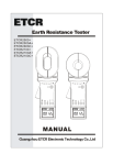
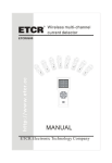
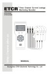
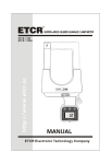
CONTENT Warning ................................................................................................ 1 I . Brief Introduction .............................................................................. 3 II. Electrical Symbols ............................................................................ 4 III.Series Model .................................................................................. 4 IV.Technical Specification .................................................................. 5 V. Structure ........................................................................................... 7 VI.LCD Display .................................................................................. 8 VII.Operation.................................................................................... 10 A. Tester Operation........................................................................... 10 1. Power On/Off ........................................................................................ 10 2. General Test........................................................................................... 10 3. PEAK Test ............................................................................................. 13 4. Data Maintenance.................................................................................. 13 5. Data Memory ........................................................................................ 13 6. Data Reference ...................................................................................... 13 7. Data Deletion ........................................................................................ 14 *8. Data Transmission ............................................................................... 14 B .Operation of Receiver .................................................................. 14 1. Power On/Off ..................................................................................... 14 2. Data Reception ................................................................................... 15 3. Data Maintenance............................................................................... 15 4. Data Memory ..................................................................................... 15 5. Data Reference ................................................................................... 15 6. Data Deletion ................................................................................... 16 VIII. Replacing Batteries .................................................................. 16 IX. Accessories ................................................................................... 17 Warning Thanks for your purchase of ETCR9000 H/L Voltage Clamp Meter of our company. In order to make better use of this product, please make sure to: ——Read this manual in detail and the operator must totally understand this manual and be in proficient in operation of this meter before making test on spot. ——Strictly comply with the security rules and notice items listed on this manual. In any case, it should pay special attention to safety in use of this meter, particularly in measurement of circuitry with more than AC100V and above voltages. If the voltage of tested circuitry has exceeded 600V, it must be used by connecting with an insulation rod. As it is very dangerous of high voltage transmission line, the operator must get strict training and the relevant certification on high-pressure operation of the state before using this meter and making a field test. It is strictly forbidden to use this meter to test the wire without any insulate protection has voltage exceed 35KV or convergence generatrix. Please pay attention to marked words and symbols on panel or backboard of this meter. Please do not put or store this meter in the place of high temperature, with moisture, with frozen dew or with direct daylight irradiation for a long time. Please note the battery polarity when replacing battery, and remove the battery if you expect not to use this meter for a long time. It must be operated by qualified staff that has the authorization on tearing down or repairing this meter. Please do not use it when there is any damage on the -1- transducer clamp or other parts of this meter. To avoid the impact of transducer clamp, it needs to maintain this meter regularly. Do not use corrosive or coarse materials to clean, but use soft cloth (such as glasses cloth), dipping clean anti-rust desiccant lubricant (such as WD-40), and making a gentle wiping. For the reason of this meter, in case that any danger may occur if continue to use it, stop using it immediately and seal it up for keeping at once, which shall be dealt with by qualified authorization agency. The danger symbol “ “on the meter and the manual, the user must make safe operation according to the indication. The extremely dangerous symbol “ ”, the user must make safe operation according to the indication. It suggests that this meter shall be made insulation intensity test at least once annually. (AC 100kV/rms between insulation pole and clamp core.) As to the part with “*”mark in this manual, it is only limited to ETCR9000B type (wireless Transmission data type). -2- I . Brief Introduction ETCR9000 Series H/L Voltage Clamp Meter has broken through the traditional structure, which is specially well-designed for measuring high voltage current, adopting the latest CT technology and integrated mask digital technology, formed by composition of a special use clamp meter with a high-voltage insulation rod, as to ETCR9000B type --- wireless transmission of test data, it is equipped with wireless receivers, which can receive measured data within 30 meters line. If not using an insulation rod, it can be also used as a high precision low-voltage clamp meter, or an alternating current meter, which can accurately measure 0.1mA of current or leakage current. ETCR9000 Series H/L Voltage Clamp Meter has an innovative integrated design between transducer clamp and transducer domain, ensuring the high-precision, high-reliability, and high-stability on constant test perennially. ETCR9000 Series H/L Voltage Clamp Meter is connected with insulation rod, which can be used for measuring high voltage current that is below 60KV, on-line current measurement, also having peak maintenance, data preservation, data storage, wireless transmission and other functions, and its special clamp meter can make it easier for clamping or evacuating the tested wire through pressing or pulling back the insulation rod, time-saving and fast, widely used in transformer substation, power plant, industrial and mining enterprises as well as the inspection station and electrician maintenance departments for electrical current detection and field electrical operations. It can also replace the H/L voltage transforming ratio tester, that is, to detect the high and low current for primary circuit and secondary circuit separately, and then calculate to conclude the change of high and low pressure. The insulation rod is light and convenient, with the advantages of anti-moisture, high temperature resistance, anti-impact, bending resistance, high insulation, flexibility and other characteristics. -3- II. Electrical Symbols Extremely Dangerous! The operator must strictly abide by the safety rules. Otherwise, there is electric injury danger, causing personal damage or casualty accident. Dangerous! The operator must strictly abide by the safety rules. Otherwise, there is electric injury danger, causing personal damage or casualty accident. Warning! It must strictly abide by the safety rules. Otherwise, it may cause personal damage or casualty accident. Alternating Current (AC) Direct Current (DC) III.Series Model Range of Model Jaw Accuracy measurement Description Specification ETCR 9000 0.0mA-1000A 0.1mA φ48mm base ETCR 9000B 0.0mA-1000A 0.1mA φ48mm wireless -4- IV.Technical Specification Function Power Supply Test Method *Transmission Method Display Mode LCD Dimension Meter Dimension Clamp Diameter Sampling Speed Range of measurement Resolution Shift Test Accuracy (23℃±5℃, Below 80%RH) Data Storage Circuit Voltage Peak High voltage AC current measurement, low voltage AC current, leakage current measurement, on-line AC current supervision. DC6V Alkaline Dry Battery (1.5V AAA X 4) Clamp CT, Integral Method B Model: Wireless Transmission, the maximum distance for direct transmission is about 30m. 4 digital LCD display, backlight function, suitable for dark place. 47mm×28.5mm W/H/T: 76mm×255mm×31mm φ48mm About 2 times/second 0.0mA~1000A(50/60Hz Auto Identification) 0.1mA 0.0mA~1000A Automatic Shift 0.0mA~299mA: ±1%±3dgt 0.30A~49.9A: ±1.5%±5dgt 50.0A~199.9A: ±2.0%±5dgt 200A~600A: ±3%±5dgt 601A~1000A: ±4%±5dgt 99 Groups, during storage, the symbol “MEM” gives indication, “FULL” mark will flash to indicate the memory has been full. Test for the circuit below 60KV (operated with insulation rod) Automatically maintain the height of the test -5- Maintenance Data Preservation Data Access Overflow Display * No signal Indication Auto Shut Down Battery Voltage Weight Work Temperature and Humidity Storage Temperature and Humidity Insulated Rod Dimension Insulation Intension Structure value, usually in the test mode press PEAK key, PEAK lights, that is, to keep open the PEAK function, then press PEAK key to cancel this function Under general test mode, press HOLD button to preserve data, “HOLD” symbol display. then press HOLD Key to cancel this function “MR” symbol indicates, it can read the stored data by turning upwards and downwards. Exceed measurement range overflow function: “OL A” symbol display When the receiver has not received transmit signal, it will display “no- -”symbol About 15 minutes after booting, the meter will shut down automatically, in order to decrease the battery consumption. When the battery voltage is below 4.8V, the symbol of battery voltage“ ”will show to remind to replace battery. Tester: About 335g (Including battery), total quality of meter: about 2.5Kg (including insulation rod and battery.) -10°C ~40°C; Below 80%Rh -10°C ~60°C; Below 70%Rh φ32mm,1m/Section(5 Sections) AC 100KV/rms (Between insulation rod and clamp core) Anti-Dripping Type II -6- V. Structure 1. Double input toroid (including the boot area) 2. ETCR9000 Tester 3. LCD Display 4. PEAK Test Indication 5. PEAK Key 6. POWER Key 7. HOLD Key *8. ETCR9000B Receiver 9. Insulation Rod Connector *10.POWER Indication *11.ETCR9000B Testers -7- VI.LCD Display 1.LCD Display Screen ⑴. AC symbol ⑵. Low battery symbol ⑶. Date storage symbol ⑷. Date access symbol ⑸. 2-digit storage data serial number ⑹. Unit symbol ⑺. Date locked symbol ⑻. Decimal system radix point ⑼. 4-Digit LCD digital display 2.Explanation for Special Symbols ⑴. Low battery symbol, when the voltage of battery is lower than 4.8V, this symbol display, please replace battery in time. ⑵.“OL A” This symbol indicates that the current on test has exceeded the maximum measurement limit of the meter. ⑶.“MEM” Memory mode, it will display during the data storage process. ⑷. “Full” symbol, when the storage memory has been filled with 99 groups of data, it will display “FULL” symbol by flash, which means it cannot continue to store data. ⑸.“MR” data access symbol, which is displayed during looking up data, meanwhile, it will display the serial number of data in storage. ⑹.“End” exit symbol, it will display during the exit. -8- ⑺.“dEL” data delete symbol, it will display when deleting data. *⑻.“no- -” None received signal instructions, dynamic display, it may not in test mode, or adjust the location and distance from receiver. 3.Display Demonstration ⑴. ——The current on test is 0.002A (2mA) ⑵. ——Locked display Data ——The data is automatic stored as group 3 ——The current on test is: 160.5A ⑶.——The current on test is: 571A ——Low battery symbol , please replace. ⑷.——Look up data of group 3 in storage ——The current on test is: 160.5A ⑸.—— “FULL” flash display: Storage is full of 99 groups ——It can’t store more unless delete storage ⑹.——“dEL” Indication of data delete ⑺.—— “End” Indication of exit *⑻.——“no- -”Dynamic display: none received signal -9- VII.Operation Please check all parts of the meter carefully before usage, to see whether there is any damage. And make sure no damage before usage. According to manual instructions to install the battery A. Tester Operation 1. Power On/Off Press POWER button to power on, the instrument will displays the LCD screen, entering normal testing mode. If LCD display is relatively dark after power on, it is possible that battery voltage is a bit lower. Please replace battery. 15 minutes after powering on the meter, if it remains idle, an auto-power off procedure starts to preserve the battery life and LCD will continue flash until the complete switch off takes place after 30 seconds. In case of LCD continuous flash, press POWER button, then the meter will continue to work. Under HOLD mode, press POWER button for power off. Under general test mode, press POWER button to power off. Under PEAK testing mode,press POWE button to power off. Under data reference mode, firstly press POWER button for more than 3 seconds to exit from data reference mode, returning to normal test mode, then press POWER button to power off. During the exit from data access, it will display “End” symbol. 2. General Test High voltage, extremely dangerous! It must be operated by qualified staff that has acquired authority. The operator must strictly abide by the -10- safety rules. Otherwise, there is electric injury danger, causing personal damage or casualty accident. Dangerous! It cannot be used to measure the circuit over 35KV voltage. Otherwise, there is electric injury danger, causing personal damage or equipment damage. Dangerous! It cannot be used to measure the circuit over 1000A voltage. Otherwise, there is electric injury danger, causing personal damage or equipment damage. General Test: In the process of test, LCD will display the tested current value real time, and LCD data will vary with the current change. When the tester is removed away from the lead on test, it does not preserve the test result, LCD display will return to zero. In normal testing mode, it is suitable for close distance measurement, convenient for circuit test by direct read of LCD data. Before test, firstly to connect insulation rod, which must be connected in right position, and then to connect tester, avoiding the impact of meter to ground surface. Make sure to use specially equipped insulation rod to connect with the meter. After test, it should incline the insulation rod accordingly on drawing in. Firstly to tear down the tester and then the insulation rod, avoiding the impact of meter to ground surface. After normal boot, place the lead in the middle of clamp transducer domain, as shown in Figure A, with the meter transducer domain perpendicular to the lead, pushing the meter forwards to clamp the lead on test, showing the result on LCD display. If showing "OL A", it means the lead current on test has exceeded the maximum volume on the level. Please select a higher gear level or a meter with greater measurement limit. To pull backwards can make the meter remove from the -11- lead on teat, as shown in Figure C, please try to keep the meter transducer domain perpendicular to the lead when moving away . Under HOLD mode, press HOLD button to cancel HOLD function, and return to normal testing mode. Under data reference mode, press POWER button for more than 3 seconds to exit from data reference mode, returning to normal testing mode. Under PEAK testing mode, press POWER button to exit from PEAK testing mode, returning to normal testing mode. After data deletion, it will return to normal testing mode automatically. Attention! For the sake of safety, when test has been finished, please remove the meter away from the lead on test. -12- 3. PEAK Test PEAK test: the maximum current test. The meter will make automatic comparison on the changes in measured current, indicating the maximum value and maintain it, when the meter is removed away from the lead on test, the test result will be kept consistently, suitable for the circuit test on those LCD data hard to be read directly. Under the normal testing mode, press PEAK button, PEAK indication light will be bright,,enter PEAK testing mode. That means the meter will display and automatically keep the maximum value in the test. Under any other mode, it must be returned to normal testing mode, and then make PEAK testing according to the above operation. Press POWER button to exit from PEAK testing mode, returning to normal testing mode, and it will display “End” symbol during the exit. 4. Data Maintenance Under normal testing mode, press HOLD button to keep LCD display, “HOLD” symbol displays. Press HOLD button again to release data lock, returning to normal testing mode, and “HOLD” symbol disappears. 5. Data Memory Under normal testing mode, press HOLD to storage data, at the same time, Meter will automatically form serial numbers, and memory the current preserved data. During the storage, “MEM” symbol will show once by flash. This meter can memory 99 groups of data, in case of full storage, “FULL” symbol will display by flash continuously, and it cannot continue to memory until cleaning out the previous memory. 6. Data Reference Under normal testing mode, press PEAK + POWER button to enter data reference mode, displaying “MR” symbol, meanwhile, it will automatically display data saved in the group 01. Then press PEAK or POWER button to read the stored -13- data by turning upwards or downwards in cycle. It will return to the group 1’s data automatically after reaching the last group’s data in storage. Press HOLD button to exit from data reference mode, returning to normal testing mode. During the exit, it will display “End” symbol. 7. Data Deletion Under data reference mode, press PEAK + POWER button to delete all the data in storage, and return to normal testing mode. During the deletion of data, it will display “dEL” symbol. *8. Data Transmission B Type: has the function of wireless data transmission. When the Meter under testing mode, the test result will be transferred to receiver by wireless transmission and the receiver will display test result real time, being clear at a glance. Only under testing mode, the meter will transmit, If the receiver has not received emission signals, it will display “no -” symbol dynamically. B Type: Transferred ETCR9000B Type: Wireless transmission test data, a straight-line distance of about 30 meters, can penetrate the floor to receive data. B .Operation of Receiver (Note: For ETCR9000B only) 1. Power On/Off Press POWER button to power on, the instrument will displays the LCD screen, entering normal testing mode. If LCD display is relatively dark after power on, it is possible that battery voltage is a bit lower. Please replace battery. 15 minutes after powering on the meter, if it remains idle, an auto-power off procedure starts to preserve the battery life and LCD will continue flash until the complete switch off takes place after 30 seconds. In case of LCD continuous flash, -14- press POWER button, then the meter will continue to work. Under HOLD mode, press POWER to power off. Under data reference, first, press POWER button( for 3 seconds ) to exit data reference mode, then come back to data receive mode, press POWER button once again to power off. During exit from data reference, it will display the symbol of “End”. 2. Data Reception After normal power on, the receiver will under receiving mode. If there are emission data, the receiver will display the test result real time. If it has not received any signal, the receiver will search signals constantly, and display “no-”symbol dynamically. 3. Data Maintenance Under Data Reception mod, press HOLD button, keep LCD display, “HOLD” symbol indication. Press HOLD button once again to relieve data lock, return to data reception mode, “HOLD” symbol display. 4. Data Memory Under Date Reception mode, press HOLD button to maintain data, meanwhile, the receiver will automatically form serial numbers, and memory the current preserved data. During the storage, “MEM” symbol will display once by flash. The receiver can memory 99 groups of data, in case of full storage, “FULL” symbol will display by flash continuously, and it cannot continue to memory until cleaning out the previous memory. 5. Data Reference Under Data Reception mode, press HOLD+POWER button to enter Data Reference mode, “MR” symbol display, meanwhile, it will automatically display data saved in the group 1. Then press HOLD button or POWER button to read the stored data by turning upwards or downwards in cycle. It will return to the group 1’s data automatically after reaching the last -15- group’s data in storage. Press POWER button for more than 3 seconds to exit from data reference mode, returning to receiving data mode. During the exit, it will show “End” symbol. 6. Data Deletion Under data reference mode, press HOLD + POWER button to delete all the data in storage, and return to Data Reception mode. During the deletion of data, it will display “dEL” symbol. VIII. Replacing Batteries Warning! In case that the battery’s cover board is not well closed, it is forbidden to make test. Otherwise, it is dangerous. Pay attention to the polarity of battery, in case of damage to the meter. Do not mix in the use of new and old batteries. 1. When the battery voltage is below 4.8V, the meter will display “ ” symbol, indicating the batteries have no sufficient power content. Please replace batteries. 2. Power off, to make sure the meter is under the state of power off. To loosen two screws of the battery cover board, open the cover board to replace brand-new qualified batteries on. It should pay special attention on the battery specification and polarity, cover the board well and fasten the two screws. 3. Press POWER button to check whether the meter can be powered on normally. If not, please repeat the operation according the step 2. -16- IX. Accessories Tester *Receiver (ETCR 9000B special ) Insulation Rod (1M/Section) Meter Box Battery (Alkaline Dry Battery AAA) User’s Manual/ Maintenance Card/ Conformity Certificate -17- 1PCS 1PCS 5 Sections 1PCS 4 PCS(* or 8 PCS) 1SET Manufactured by ETCR Electronic Technology Company Address: F-3F, No.4 Pengshang Zhifu Road, Jiahe, Baiyun District, Guangzhou, Guangdong, China Post Code: 510440 Tel: (86-20)62199556 62199554 Fax: (86-20)62199550 E-mail: [email protected] Website: www.etcr.cc