1
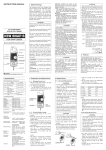
CONTENT
Warning ................................................................................................ 1
I. Brief Introduction ............................................................................... 3
II. Electrical Symbol .............................................................................. 4
III. Current Clamp Model ...................................................................... 4
IV. Technical Specifications ................................................................. 4
V. Instrument Structure ........................................................................ 7
VI. Instrument Operation ...................................................................... 8
1. Turning on and off ........................................................................... 8
2. Selecting Power-saving Mode ........................................................ 8
3. Date and Time Setting .................................................................... 8
4. Auto Record Internal Setting .......................................................... 9
5. Data Inquiry .................................................................................... 9
6. Deleting Data ................................................................................ 10
7. Leakage/current measurement .................................................... 11
8. Real-time Monitoring .................................................................... 12
9. Data Download ............................................................................. 12
VII. Replacing Battery ......................................................................... 13
VIII. Accessories ................................................................................. 14
Warning
Thanks for your purchase of ETCR8500 Wireless Multi-Channel Current
Monitor of our company. In order to make better use of this product, please
make sure to:
——Read the User Manual carefully.
——Keep to the safety rules and precaution given in the manual strictly.
u
In any circumstance, it shall pay special attention on safety in use of this
tester.
u
Pay attention to words and symbols stick on the tester.
u
Please replace the battery with a new one when the battery voltage is so
low that the LCD display is dim.
u
This instrument cannot be turned off automatically. Please turn off it after
use. The use of the environment to avoid the 433mHz±100kHz signal
interference
u
Don not use the instrument to measure a line with voltage higher than
600V.
u
It is forbidden to use the instrument when neither rear cover of the
instrument nor the battery cover is in place.
u
The user can choose 1-8 channel according to need of current
monitoring
u
The user can according to need to choose different current clamp jaw
-1-
size
u
Never use the instrument when the instrument case or measuring wire is
broken and therefore any metallic part is exposed.
u
Don not place the instrument at a environment with high temperature,
high humidity, condensation and direct sunshine for a long time
u
It is necessary to maintain the instrument and clamp periodically to keep
them clean. Don not wipe the clamp by using corrosive medium or
abrasive object.
u
Avoid impact upon the current clamp, especially its mating surface
u
Please observe the correct polarity when replacing the battery. Remove
the battery from the instrument if you expect not to use the instrument for
a long time.
u
Operation, disassembly and repair of the instrument must be carried out
only by a authorized and qualified person
u
When there is an instrument fault, never use it because continual use
may result in danger. In this case, isolate the instrument immediately and
delivered to an authorized agency for dealing with it.
u
The user must follow the safety instructions preceded by “
”warning
symbol on the instrument and manual.
u
The user must follow observe the instructions preceded by “
symbol on the instrument and manual.
-2-
”danger
I. Brief Introduction
ETCR8500 Wireless Multi-Channel Current Monitor is well designed and
manufactured for online measurement, monitoring and recording of 1-8
channel AC leakage / current at the same time. Using wireless transmission
the data, the transfer distance is 80m. The wireless transmission signal is able
to penetrate obstacles, such as the partition of the metal. It is composed of a
tester, current clamp, monitoring software and communication cable, etc.
Widely used in electric power , telecommunications , meteorology, railways,
oil, construction, measurement, research and teaching unit , the mining
industry and other fields. It is convenient, fast and accuracy.
The instrument has built-in wireless transmitting module, 1-8 channel current
value can be display on the LCD screen, 3000 sets of data can be stored in
the instrument. System clock can be set. In addition, the instrument can
automatically store data at an interval, which is adjustable from 1 to 120 min.
The current clamp is made of a special alloy, has built-in wireless transmitting
module, adopts the latest CT technique and magnetic shielding technique and
is not almost interfered by external magnetic field. This ensures high accuracy,
high stability and high reliability of the values which are measured
continuously. The user can according to the cable, line, or busbar thickness of
different specifications of the current clamp of choose and buy, it is very
practical.
Monitoring software provides online and real-time monitoring and historical
data inquiry. With the software developed by our technical department, the
users can read, inquire, store, generate and print a fitting curve and report.
-3-
II. Electrical Symbol
Extremely dangerous!The operators must keep to the safety rules
strictly; otherwise, electric shock will result in death or injury.
Dangerous!The operators must keep to the safety rules strictly,
otherwise, electric shock will result in will result in death or injury.
Warning!The operators must keep to the safety rules strictly,
otherwise, personal injury or equipment damage will occur.
Double insulation
Alternating current (AC)
Direct current (DC)
III. Current Clamp Model
Range
Resolution
Clamp size
030S
0.000mA~60.00A
1uA
25mm×30mm
040S
0.00mA~300.0A
0.01mA
35mm×40mm
068S
0.00mA~1200A
0.01mA
φ68mm
Model
IV. Technical Specifications
Functions
8-Channel AC Current, Leakage Current, Load Wireless
Monitoring
Host: DC6V, alkaline battery LR6 1.5V×4
Power Source
Current Clamp: Zn-Mn dry battery: 6F22 9V(External
power supply)
Channel NO.
8-Channel simultaneity monitoring (can be adjusted
according to customer needs)
-4-
Wireless Transfer
80m
Distance
Clamp Size
(Option)
030S:25mm×30mm
040S:35mm×40mm
068S:φ68mm
030S:0.000mA~60.00A
Range
040S:0.00mA~300.0A
068S: 0.00mA~1200A
030S:1uA
Resolution
040S:0.01mA
068S:0.01mA
Measurement
Accuracy (23℃±
3℃,≤70%RH)
Testing Methods
Current
0.000~59.9A:1.5%±5dgt
60.0A~299A: 2.0%±5dgt
300A~599A: 3.0%±5dgt
600A~1200A: 4.0%±5dgt
Clamp CT, TRMS
50Hz/60Hz automatic recognition
Frequency
Shift
Display Mode
Automatic shifting
LCD: 128dots×64dots
Host:170mm×75mm×30mm
Tester Size
030S:175mm×70mm×38mm
040S:180mm×70mm×38mm
068S:224mm×115mm×43mm
Host:240g(include battery)
Weight
030S: 120g(include battery)
040S: 140g(include battery)
068S:515g(include battery)
LCD Frame
Window Dimension:44mm×27mm
-5-
Dimension
Shield Property
Line Voltage
Sampling Rate
Data Storage
Communication
Frequency
RS232 Interface
Communication
Wire
Time Setting
Time Record
Overflow Display
Current clamp with double shielding technology, strong
anti-jamming capability
Below AC600V line test
About 2 times / second
3000sets (Power-down or replace the battery without
losing data)
433MHz±100KHz Wireless transfers
Data storage, up-load
1.5m
1 to 120 minutes set the logging interval, 0 minutes is not
automatically stored
Under the power-saving mode continuously work for
about 3 days
Exceeding measuring range overflow function: “OL” icon
display
When the battery voltage of host is bellow 4.8V,low
Voltage sign will be displayed to remind the user of
replacing the battery;
Battery Voltage
When the battery voltage of current clamp is bellow
7.2V, power light will continue to flicker, it means
Electric power shortage, please replace the battery. In
this case ,the measured data is still accurate
Rated Power
Under saving model about 5mA, Max 20mA
Temperature and
Working: -20℃~50℃;below 80%rh
Humidity
Storage: -10℃~60℃;below 70%rh
-6-
Insulation and
Pressure
Safety Rules
Safety Rules
More than 100MΩ, AC2kV/rms ( Between shell and
screw)
IEC1010-1,IEC1010-2-032,Pollution
Degree:2,CATIII(600V),IEC61326(EMC)
Host:1pcs;Clamp:1~8pcs;RS232Cable;Software(CD):1pc
s; Bag:1pcs
V. Instrument Structure
1. LCD(128dots×64dots)
2. Up, down, left, right keys and MEM control key
3. Host POWER key (for turning on and turning off the instrument)
4. RS232 interface for data download
5. Current clamp
6. Low voltage power supply and battery indicator light
7. Current clamp POWER key (for turning on and turning off the instrument)
8. Monitor the channel number
9. The trigger (control jaw opening and closing)
-7-
VI. Instrument Operation
1. Turning on and off
Turn on the instrument by pressing the POWER / ON/OFF key. The LCD
/LED will light up. If the LCD display is dim or the LED blink, the battery
voltage may be low. If so, replace the battery with a new one. Press the
POWER / ON/OFF key again to turn off the instrument.
This instrument cannot be turned off automatically. Please turn off it after use.
2. Selecting Power-saving Mode
Press the DOWN arrow key at the measurement status to turn off the LCD
back-light and enter the power-saving mode. Press the UP arrow key to turn
on the backlight. The power consumption at the power-saving mode is only 20
percent of the one at the common mode (the backlight is turned on). It is
recommended that the power-saving mode be adopted for long-time online
measurement and recording.
3. Date and Time Setting
Press the MEM key at the measurement state to access the function menu,
press the UP or DOWN arrow keys to move the cursor to the Time Setting
item, and press the MEM key again to enter the date& time setting mode. At
the date& time setting mode, press the UP/DOWN arrow keys to change
values, press the LEFT or RIGHT keys to move the cursor, press MEM key to
“confirm” or “cancel” the setting.
After the recording interval has been set, return to the measurement state.
The instrument will automatically store the measured values at the set interval.
The instrument can store up to 3900 data sets. If the memory is full, FULL will
be displayed on the LCD. The instrument can store new data only after some
of stored data is deleted.
-8-
4. Auto Record Internal Setting
Under the test mode, press UP and Down array to set the internal time for
automatically record. The internal time can be set from 1 to 120 min. “000
min” means auto record function is closed, which is default setting after each
boot up.
Test Menu
Time Menu
The instrument doesn’t have automatic clock function. The date
and time will reset to the default value each time the instrument
is turned on.
The storage interval is defaulted to “000” min each time the
instrument is turned on, that is to say, no measured value is
stored.
5. Data Inquiry
At the measurement state, press the MEM key to access the function menu,
press the UP or DOWN arrow keys to move the cursor to “Data Inquiry” item,
and press the MEM key to enter the inquiry submenu. Press the LEFT and
RIGHT arrow keys under the inquiry submenu to move the cursor can select
the page number increment and decrease. It is allowed to rapidly navigate to
the desired page number. Press the MEM key to confirm the selection.
Under the inquiry submenu, display the detailed information about this data
set, including the set number, current amplitude and recording time, etc.
-9-
In figure 2 state,press the up button to enter into the state of figure 3 shows a
more comprehensive array of current.
In figure 3 state, press the left key can enter information such as figure 4
shows the current array of time. According to relevant interface as follows:
figure 1
figure 2
figure 3
6. Deleting Data
figure 4
At the measurement state, press the MEM key to access the function menu,
press the UP or DOWN arrow keys to move the cursor to “Deleting Data” item,
When press the MEM key again, a data deleting tips will pop up. Press the
MEM key with the cursor located at “YES” to delete the stored data. Press the
MEM key with the cursor located at “NO” to cancel the deletion and return to
the main menu.
It is impossible to recover the deleted data. Take care to delete any
data.
The deletion operation will delete all of the stored data.
-10-
7. Leakage/current measurement
Electric shock, dangerous!The instrument can be operated only by
the trained and authorized person. The operators must keep to the
safety rules strictly, otherwise, electric shock will result in personal
injury or damage to the equipment.
Don not use the instrument to measure the lines with a voltage of
higher than 600V and current of higher than 20A, Otherwise, electric
shock will result in personal injury or damage to the equipment.
1)Boot into test mode, the wireless signal is abnormal or current clamp didn't
boot is displayed "-- -"
2) Clamp the measured object with the current clamp (ensure that the clamp
end should be fully closed). Observe the reading. If an OL symbol is displayed
on the instrument LCD, the measured current exceeds the upper
measurement limit of the instrument.
3) Reference legend:
In order to measure the leakage current of an electrical equipment,
clamp the phase line and neutral line. (take care to clamp the two
lines)
In order to measure the leakage current of a ground conductor,
clamp the ground conductor. (take care to clamp only one
conductor)
In order to measure the total current of a main line, clamp this main
line. (take care to clamp only one line).
For the sake of safety, remove the instrument away from the
conductor with high voltage and current after measurement has
been completed correctly
-11-
8. Real-time Monitoring
Turn on the instrument and enter the measurement state. Connect a PC with
the instrument via a RS232 communication cable supplied with the instrument.
Run the software installed in the PC. If the communication is normal, the users
can monitor current in real-time manner via the PC.
The software can display leakage current dynamically, display current
waveform, maximum value, minimum value and average value. In addition,
the users can read, inquire, store, analyze, process, sequence historical data
and generate and print a fitting curve and report.
Historical data can save as TXT file.
9. Data Download
Connect the instrument with the PC via the RS232 communication cable
(supplied with the instrument) and turn on the instrument. Run software, select
the Historical Inquiry and read the data. The more the data is, longer time it
takes to read them. If the instrument memory is full, it takes about 2min to
read all data.
-12-
VII. Replacing Battery
Observe the correct battery polarity, Otherwise, the instrument
will be damaged.
Replace the battery with a new one as soon as possible when the
battery voltage is low.
Don not use the new battery together with an old battery.
1) When the battery voltage drops to 4.6V to 4.8V, a
symbol will be
displayed on the instrument, indicating the battery voltage is low. Replace the
battery immediately.
When the battery voltage of current clamp is bellow 7.2V, power light will
continue to flicker, please replace the battery.
2) Press the POWER key to turn off the instrument. After confirming that the
instrument has been turned off, open the battery cover and replace with a new
battery recommended by the manufacturer. Pay special attention to the
correct battery polarity. Replace the battery cover, turn on the instrument and
confirm that the instrument can operate properly. (as shown in the following
figure)
-13-
VIII. Accessories
Tester
1 PCS
Current clamp
1-8 PCS (selective
purchasing)
RS232 communication cable
1 PCS
ETCR monitor software (CD-ROM)
1 PCS
Instrument bag
1 PCS
Alkaline battery (AAA 1.5V)
4 PCS
Zinc-manganese Dry Battery 6F22 9V
8 PCS
User manual 、 Warranty card and quality
1 SET
certificate
-14-
Manufactured by
ETCR Electronic Technology Company
Address: F-3F, No.4 Pengshang Zhifu Road, Jiahe, Baiyun
District, Guangzhou, Guangdong, China
Post Code: 510440
Tel: (86-20)62199556 62199554
Fax: (86-20)62199550
E-mail: [email protected]
Website: www.etcr.cc