1
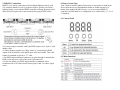
TABLE OF CONTENTS
1. Safety Instructions
2. Technical Specifications
3. Installation
4. How to Connect the Fixture
5. DMX512 Configuration
6. DMX512 Connections
7. How to Set the Unit
8. Troubleshooting
9. DMX General Information
1. Safety Instructions
• Please keep this User Manual for future consultation. If you sell the
fixture, be sure to include this instruction booklet to ensure proper
maintenance and use.
• Unpack and check carefully for transportation damage before using the
fixture.
• Before operating, ensure that the power supply voltage and frequency
match the power of your electrical system.
• It's important to connect the yellow/green conductor to ground to avoid
electric shock.
• Disconnect main power before servicing and maintenance.
• Use a safety cable when permanently mounting this fixture. Always
handle the fixture with care.
• Maximum ambient temperature is 104° F.
• In the event of a serious operating problem, stop using the fixture
immediately. Please contact the dealer from whom you purchased the
fixture or Talent Sound & Lighting directly.
• Do not connect the device to any dimmer pack.
• Do not touch exposed wires during use, as there might be a hazard of
electrical shock.
• To prevent or reduce the risk of electrical shock or fire, do not expose
the fixture to rain or moisture.
• The fixture must be replaced if there is visible damage to the housing.
• Do not look directly at the LEDs while the fixture is on.
Warning: Please read the instructions carefully. They include important
information about installation, operation, and maintenance. Do not
connect more than 32 units in series (daisy-chaining) on a single power
circuit.
Caution: There are no user serviceable parts inside the fixture. Do not
open the housing or attempt any repairs yourself. In the unlikely situation
your unit may require service, please contact your dealer or Talent Sound
& Lighting.
2. Technical Specifications
• DMX channels: 2/7/10/31
• 252 Ultra Bright 10 mm LEDs (Red: 63, Green: 63, Blue: 63, White: 63)
• Auto, sound active, DMX, and master/slave modes
• Internal programs with sound activation
• IEC power in/out sockets
• 3-pin XLR in/out sockets for DMX control
• Slimline robust aluminum housing
• RGBW color mixing
• Beam angle: 40°
• Power consumption: 23 watts
• Dimension: 42.91" L x 2.64" H x 2.64" W
• Weight: 4.07 lbs.
3. Installation
The unit should be mounted via its screw holes on the bracket. Always
ensure that the unit is installed to avoid vibration while operating. Always
ensure that the structure to which you are attaching the unit is secure and
is able to support a weight of 10x this fixture's weight (40.7 lbs.) Always
use a safety cable that can hold 12x the weight of the fixture.
4. How to Connect the Fixture
3-Pin and 5-Pin XLR DMX Connectors:
Some manufactures use 5-pin XLR connectors for data transmission. 5-pin
XLR fixtures may be implemented in a 3-pin XLR DMX line. When
inserting standard 5-pin XLR connectors into a 3-pin line, a cable adapter
must be used.
5. DMX512 Connections
DMX512 is a widely used protocol for intelligent lighting control, with
512 available channels. Even if you do not wish to operate your Talent
lighting fixture via an outboard DMX controller, utilizing the master/slave
mode will still require unit-to-unit connection by proper DMX cables.
6. How to Set the Unit
Your Talent Sound & Lighting fixture may be operated as a stand-alone
device that runs on pre-programmed routines or sound activation, in
master/slave mode with other devices, or via an external DMX512
controller. In DMX mode it is configurable to be controlled by 2, 7, 10, or
31 channels.
6.1 Control Panel
• If you are using a controller with 5-pin DMX output, use a 5-pin to 3-pin
adapter cable.
• Connect fixtures together in a "daisy chain" by connecting the DMX
output of the first fixture to the DMX input of the next fixture. This cable
cannot be branched or split by a "Y" cable.
• The DMX output and input connectors are pass-through to maintain the
DMX circuit if power to one of the units is disconnected.
• On the last fixture, the DMX output should be terminated with a
terminator with a 120 ohm resistor between pins 2 and 3 to reduce signal
errors.
6.2 Main Functions
Sound Active Modes:
Mic sensitivity is adjustable on a 0 to 9 scale. Two sound active modes
containing 10 effects each may be selected. Use the <UP> button to scroll
through the dB meter and sound active modes (1st & 2nd digits) on the
menu, and the <DOWN> button to adjust the program (3rd & 4th digits).
S --- <ENTER> Sound Active Modes
S000 - S009 dB Meter Adjusts Microphone Sensitivity
S100 - S109 Sound Active 1, Silence Starts the Effect
S200 - S209 Sound Active 2, Silence Stops the Effect
Slave Mode
1.) To configure the fixture as a slave unit, scroll to A---, and select
<ENTER>. Use the <UP/DOWN> buttons to navigate to A 0n. Press the
<ENTER> button once again to confirm the setting.
Manual Color Adjustment:
Controls color balance. All other modes are affected by these global
settings.
r255: r000 - r255
Red Custom Color Adjustment
G255: G000 - G255 Green Custom Color Adjustment
b255: b000 - b255
Blue Custom Color Adjustment
U255: U000 - U255 White Custom Color Adjustment
1.) The <MENU> and <UP/DOWN> button may be used to select rL-(Red Level), GL-- (Green Level), bL-- (Blue Level), or UL-- (White
Level). Using the <UP/DOWN> buttons, select the maximum level for
each color, x000x255 (000 = off), then press <ENTER> to confirm the
setting.
DMX Mode
The unit is controllable by most brands of DMX controller. Each lighting
fixture needs to have an address set when in DMX mode, to receive the
data sent by the controller. The address number is between 0-511 (usually
0 & 1 are equal to 1).
1.) The default starting DMX address for the fixture is A001 on the LED
readout. To select a different starting DMX address, use the <UP/DOWN>
buttons to select the starting address you wish to use, and press the
<ENTER> button to confirm your choice.
2.) To select which channel mode you would like to use, set the value of
DMX Channel 1 as desired.
7. DMX512 Configurations
8. Troubleshooting
Here are some troubleshooting suggestions:
A. The fixture does not work, there is no light output.
1.) Check the connection of power and main fuse.
2.) Measure the voltage output on your power receptacle to ensure proper
voltage.
B. Fixture does not respond to DMX control.
1.) DMX LED should be on. If not, check DMX connectors and cables for
proper connection.
2.) If DMX LED is on but not responding to a channel, check the DMX
address settings and DMX polarity.
3.) If you have intermittent DMX signal problems, check the pins on the
cable connectors and on the fixture.
4.) Try to use a different DMX controller.
5.) Ensure DMX cables aren't run along high voltage cables.
C. Fixture responds erratically to DMX control.
1.) You may have a break in the DMX cabling. Check the LED for the
response of the master/ slave mode signal.
2.) Wrong DMX address in the fixture. Set the fixture to the proper
address.
3.) Use of microphone cables for DMX connections can cause errors
D. The fixture doesn't respond to sound.
1.) Make sure the fixture is not set to receive a DMX signal.
2.) Check the fixture's internal microphone by tapping the microphone.
For additional details about DMX operation, please review
Section 9: DMX General Information.
9. DMX General Information
The DMX standard features 512 available channels. Each DMX-capable
fixture requires one or more sequential channels. A starting address, which
indicates the first control channel reserved for that particular fixture, must
be assigned to the fixture before the controller can recognize it. DMX
controllable fixtures may vary in the number of channels they require,
depending on the fixtures features and/or functionality.
Channels should never be permitted to overlap; otherwise, for example, a
fader that controls blue output on one fixture may cause strobing or
dimming on an adjacent, incorrectly assigned fixture. Multiple fixtures of
the same type that use an identical starting address will function in unison.
Fixtures assigned properly spaced starting addresses will operate
individually, but a DMX controller with sufficient channels can be
configured to run these same fixtures either combined or independently.
The sequence in which DMX fixtures are connected has no effect on how
a controller communicates with each individual fixture. Although 3-pin
XLR mic cables may be used to connect DMX fixtures over short runs,
longer distances will introduce data errors due to the mic cable's incorrect
impedance. For best results, Talent Sound & Lighting recommends the use
of correct 120 ohm, low-capacitance, twisted pair cable designed for the
DMX512 protocol. It is also suggested that a termination resistor plug be
used on the output connector of the last fixture in an array of DMX
instruments. This resistance ensures proper data transmission.
Notes: