1
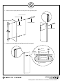
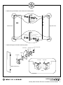
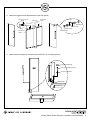
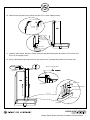
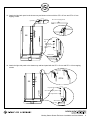
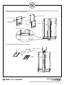
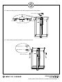
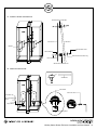
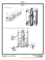
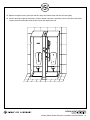
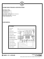
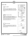
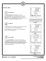
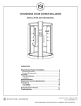
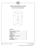
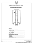
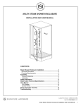
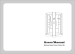
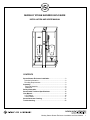
MURSLEY STEAM SHOWER ENCLOSURE
INSTALLATION AND USER MANUAL
CONTENTS
Steam Shower Enclosure Installation........................................2
Technical Information...................................................................2
Plumbing Requirements..............................................................2
Assembly.......................................................................................2
Tools and Materials.....................................................................2
Installation..................................................................................2
Safety Information......................................................................15
Steam Cabin Technical Specifications.....................................16
User Manual................................................................................16
LCD Display..............................................................................16
Control Panel............................................................................17
Steam Generator Cleaning........................................................21
Troubleshooting..........................................................................22
Mursley Steam Shower Enclosure Installation and User Manual
1
STEAM SHOWER ENCLOSURE INSTALLATION
Before you begin, read the following installation and care instructions. Observe all local plumbing, building, and electrical
codes.
Unpack and inspect the product for any shipping damages. If you find damages, do not install. Contact Customer Service
at 1.866.855.2284. If you need assistance or have questions while installing your shower enclosure, contact Customer
Service.
We recommend that all plumbing and electrical rough-in work be completed by a professional prior to shower enclosure
assembly. Signature Hardware accepts no liability for any damage to the enclosure, walls, floor, or for personal injury
during installation.
TECHNICAL INFORMATION
•
•
•
220 volt, 20 amp GFCI breaker
Line 1, line 2 and ground (1 dedicated line for steam)
The size of breakers and wire gages is determined by local, state, and national codes as interpreted by the installing
electrician.
PLUMBING REQUIREMENTS
•
•
•
•
This unit is equipped with hot and cold braided water supplies with ½" NPT pipe threads.
Install hot and cold shut off valves with ½" male NPT pipe threads to connect to water supplies.
Tighten all connections prior to installation.
We recommend preparing the drain location with the shower enclosure base on site. A drain pipe 2" in diameter is
required, hose can stretch 6".
ASSEMBLY
TOOLS AND MATERIALS:
Level
Caulking Gun
Set Square
Screwdriver
Adjustable Wrench
Rubber Mallet
Silicone Sealant
Drill
INSTALLATION
1. Set the shower tray in place. Place a level on the tray and adjust the tray legs as necessary until completely
straight. Each leg should be touching the floor.
Adjustable Foot
Mursley Steam Shower Enclosure Installation and User Manual
2
2. Attach the hand spray slide bar and wall post to the right back panel.
M4 x 25 mm Screw
M4 Black O-ring
Hand Spray Slide Bar
Philips Screwdriver
M4 Gasket
M4 x 25 mm Screw
3. Attach the shower basket and wall post to the left back panel.
M4 Nut
Left Back
Glass Panel
M4 Gasket
M4 Black O-ring
Small Copper Meson
M4 x 25 mm Screw
Small Decorative Cap
Shower Basket
Mursley Steam Shower Enclosure Installation and User Manual
3
4. Attach the top and bottom corner braces to the back panels.
Top Corner
Brace
Left Back Panel
Right Back Panel
Decorative Cover
2 Black Gaskets
Bottom Corner Brace
2 Black Gaskets
M6 x 10 mm Screw
5. Attach the hinges to the back and door panels.
Glass Panel
Hinge Back Cover
M4 x 12 mm Screw
Gasket
Gasket
Hinge Body
Left Back Panel
Door Panel
Door Panel
Right Back Panel
Left Back Panel
Hinge
Mursley Steam Shower Enclosure Installation and User Manual
4
6. Attach the top and bottom corner braces to the side panels. These will attach the side panels to the top cover.
Decorative Cover
Right Side Panel
M6 x 10 Nut
2 Black Gaskets
2 Black Gaskets
Top Corner Brace
M6 x 10 mm Screw
Left Side Panel
Right Side Panel
Bottom
Corner Brace
7. Attach the magnetic seals ceiling panels.
Decorative Cover
2 Black Gaskets
Shower Ceiling
Top Corner Brace
M6 x 10 mm Screw
Left Ceiling Panel
Right Ceiling Panel
2 Black Gaskets
Magnetic Seal
Mursley Steam Shower Enclosure Installation and User Manual
5
8. Attach the magnetic seals and handle set to the door panels.
Adjust screws on door
handle
Door Panel
Gasket
Decorative Cover
M5 x 20 mm
Machine Screw
Door Panel
Interior Door
Handle
Decorative
Cover
Magnetic Seal
2 Black Gaskets
2 Black Gaskets
Exterior Door
Handle
Decorative Cover
9. Attach the left back panel to the shower tray with ST4 x 16 mm tapping screws.
Large Decorative Cap
ST4 x 16 mm Tapping Screw
Large Copper Meson
White Gasket
Shower Tray
Mursley Steam Shower Enclosure Installation and User Manual
6
10. Attach the left side panel to the shower tray with ST4 x 16 mm tapping screws.
ST4 x 12 Tapping Screw
Large Decorative
Cap
ST4 x 16 mm
Tapping Screw
Large Copper Meson
White Gasket
Shower Tray
11. Install the back column. Attach the column to the left wall panel and shower tray with the ST4 x 25 mm and
ST4 x 20 mm tapping screws.
12. Connect the flexible water feed tubes from the column to the corresponding outlets on the shower tray.
ST4 x 25 mm Tapping Screw
(1) Insert
Back Column
(2) Connect
ST4 x 20 mm Tapping Screw
Water Feed Tubes
Shower Tray
(3) Attach
Mursley Steam Shower Enclosure Installation and User Manual
7
13. Attach the right back panel to the shower tray and shower column with the ST4 x 25 mm and ST4 x 16 mm
tapping screws.
ST4 x 25 mm Tapping Screw
(1) Insert
Large Decorative
Cap
ST4 x 16 mm
Tapping Screw
Large Copper
Meson
White Gasket
Shower Tray
14. Attach the right side panel to the shower tray and back panel with the ST4 x 12 mm and ST4 x 16 mm tapping
screws.
ST4 x 12 mm
Tapping Screw
Large Decorative Cap
ST4 x 16 mm Tapping Screw
Large Copper Meson
White Gasket
Shower Tray
Mursley Steam Shower Enclosure Installation and User Manual
8
15. Remove the screws from the top and bottom of the front column. Attach the main body of the front column to the
shower tray with ST4 x 16 mm tapping screws.
Front Column Main Body
ST4 x 20 mm Tapping Screw
Small Decorative Cap and
Copper Meson
Front Column
Cover
ST4 x 16 mm Tapping Screw
16. Install the ceiling shower between the two columns.
ST4 x 35 mm Tapping
Screw
Ceiling Cover
Shower
Ceiling
Mursley Steam Shower Enclosure Installation and User Manual
9
17. Connect the flexible water feed tubes, steam generator drain tube and ground wire from the column to the
corresponding outlets on the shower tray. Connect the electrical wiring from the column to the corresponding
outlets on the front cover.
Power Supply
8.1 (exhaust fan)
8.2 (chromatherapy lamp)
8.3 (speaker)
Front
Column
Cover
4 (display)
Ground n
Wire
(1) Shower Ceiling
3 (touch panel)
Jet
Handshower Steam Generator Drain
Cold Water Supply
connect through shower ceiling
Hot Water Supply
connect through shower
ceiling
Hot Water Supply
(3) Jet
(2) Hand Shower
Ground Wire
Steam Generator Drain
18. Attach the front cover with the ST4 x 20 mm tapping screws.
Front Column Main Body
ST4 x 20 mm
Tapping Screw
Small Decorative Cap
Copper
Meson
Front Column Cover
Mursley Steam Shower Enclosure Installation and User Manual 10
19. Attach the ceiling panels to the side and back panels and the ceiling shower.
Shower Ceiling Cover
ST4 x 12 mm Tapping Screw
Left Ceiling Panel
Shower Ceiling
Left Ceiling Panel
20. Finish installing assembly hardware to secure the top cover.
Decorative Cover
2 Black Gaskets
M6 x 10 mm Screw
Mursley Steam Shower Enclosure Installation and User Manual
11
21. Install the shower seat backrest.
Stainless Steel Threaded Rod
Back Panel
Backrest
Backrest
Stainless Steel Screw
2 Black Gaskets
Stainless Steel Decorative Ring
M8 x 25 Hex Screw
Stainless Steel Threaded Rod
22. Attach the shower seat.
Seat Bracket
Seat Bracket
Interior Hex Screw
Decorative Cap
St 5 x 25 Tapping
Screw
Copper Meson
Bracket Fixing Block
Mursley Steam Shower Enclosure Installation and User Manual 12
21. Install the door panels.
Hinge Back Cover
M4 x 12 mm Screw
Gasket
Door Panel
Hinge Body
Gasket
22. Install the seal strips according to the drawing specifications to prevent leakage.
Side Panel
Door Panel
Front Column
Door Panel
Door Panel
309D Seal
309A Seal
Shower Tray
Mursley Steam Shower Enclosure Installation and User Manual 13
23. Adjust the magnetic seals, glass clips and door hinge as needed so that the door will close tightly.
24. Connect the water supply and electricity. Push the shower into place if necessary. Use a screwdriver and rubber
mallet to push the seal strips inside the door frame flush against the wall.
Mursley Steam Shower Enclosure Installation and User Manual 14
SAFETY INFORMATION
•
•
•
•
•
•
•
•
When using this unit, basic safety precautions should always be followed.
Children under the age of 16 should not be permitted to use the steam shower enclosure.
Use this unit only for its intended purposes as described in this manual. Do not use any additional attachments not
recommended by the manufacturer.
Never drop or insert objects into openings in the steam shower enclosure.
The unit must be connected to a supply circuit that is protected by a ground-fault circuit-interrupter (GFCI). The appropriate GFCI should be provided by the installer and should be tested on a routine basis.
To test the GFCI, push the Test button. The GFCI should power off. Push the Reset button to restore the power. If
the GFCI fails to operate in this matter, it is defective.
If the GFCI fails to provide power to the shower enclosure and a ground current is flowing the user could potentially incur an electric shock. Do not use the shower enclosure and repairs performed by a qualified electrician before
using.
A green-colored terminal (or wire connector marked “G”, “GR”, or “Ground”) is provided within the front column. To
reduce the risk of electric shock, connect this terminal or connector to the grounding terminal of your electric service
or supply panel with a connector equivalent in size to the circuit of the conductors supplying this equipment.
To reduce the risk of injury:
•
•
•
The wet surfaces of steam enclosures may be slippery. Use care when entering or leaving.
The steam head is hot. Do not touch the steam head and avoid the steam near the steam head.
Prolonged use of the steam system can raise internal body temperature and impair your body's ability to regulate
temperature (hyperthermia). Limit steam use to 10 – 15 minutes at a time until you are certain of your body’s
reaction.
• Excessive temperatures have a high potential for causing fetal damage during the early months of pregnancy.
Pregnant or possibly pregnant women should consult a physician regarding correct exposure.
• Obese persons and persons with a history of heart disease, low or high blood pressure, circulatory problems, or
diabetes should consult a physician before using the steam system.
• If using medication, consult a physician before using the steam system as some medication may induce drowsiness
or affect heart rate, blood pressure and circulation.
Hyperthermia warning:
Hyperthermia occurs when the internal temperature of the body reaches a level several degrees above the normal body
temperature of 98.6° F. The symptoms of hyperthermia include dizziness, lethargy, drowsiness, and fainting. The effects
of hyperthermia include:
• Failure to perceive heat
• Failure to recognize the need to exit the steam shower
• Unawareness of impending risk
• Fetal damage in pregnant women
• Physical inability to exit the steam shower
•Unconsciousness
WARNING – The use of alcohol, drugs, or medication can greatly increase the risk of hyperthermia
Mursley Steam Shower Enclosure Installation and User Manual 15
STEAM CABIN TECHNICAL SPECIFICATIONS
Rated Power: 3.0 KW
Rated Voltage: AC240V
Rated Electric Current: 16A
Frequency: 60 Hz
Power Supply Location: Wall
Water Supply: ½" NPT pipe thread, hot/cold water
Water Supply Location: Wall
Diameter of Drainage Pipe: 1-½" flex pipe
Length of Drainage Pipe: 39"
USER MANUAL
LCD Display
1. Fahrenheit
2. Celsius
3. Temperature
4. Temperature Indicator
5. Timer Setting
6. FM Radio Function
7. FM Radio Volume
8. FM Radio Channel
9. Chromatherapy ON/OFF
10. Fan ON/OFF
11. Steam ON/OFF
12. Power ON Indicator
13. FM Radio Channel
14. MP3 ON/OFF
Mursley Steam Shower Enclosure Installation and User Manual 16
CONTROL PANEL
Steam Cabin Control Panel
Power ON/OFF
Steam Temperature Setting
Steam Timer Setting
Fan ON/OFF
Chromatherapy
Steam ON/OFF
MP3
Radio
Volume/Channel
Radio Settings
+ Adjustment
- Adjustment
Steam Cabin Control Parts
1. Steam Temperature Sensor
2. LCD Display
3. Control Panel
4. Water Diverter
5. Water Volume Adjustment
6. Water Temperature Adjustment
7. Back Massage Jet
8. Steam Outlet
9. Hand Shower Set
10. Steam Generator Cleaning Liquid Jet
Mursley Steam Shower Enclosure Installation and User Manual 17
CONTROL PANEL
Power ON/OFF
Push any button to light the display (Image 1). Push the Power
button to turn the system on (Image 2) and off. When the power
is turned off, the display and background light shuts off immediately
while the drain valve for the steam generator remains running for
one minute.
Image 1
Steam Temperature Setting
The default steam temperature setting is 113 degrees. To adjust the
temperature, push the Steam Temperature Setting button
(Image 3) until the desired temperature is reached. When the cabin
temperature reaches 4 degrees above the set temperature, the
steam generator automatically shuts off. When the cabin
temperature reaches 4 degrees below the set temperature the
steam generator automatically turns on.
Image 2
Steam Timer Setting
The default steam timer setting is 45 minutes. To adjust the timer
setting, push the Steam Timer Setting button (Image 4) until the
desired time is reached. The system automatically shuts off at the
end of the specified time.
Image 3
Image 4
Mursley Steam Shower Enclosure Installation and User Manual 18
CONTROL PANEL
Chromatherapy
The Chromatherapy button controls the color of the
chromatherapy lights. The chromatherapy symbol on the LCD
display flashes when the chromatherapy lights are turned on
(Image 5). Press the Chromatherapy button to adjust the turn the
lights on and off and to adjust the lights as desired.
Image 5
Image 6
Fan ON/OFF
The Fan button turns the ventilation fan on and off. When the fan is
running, the fan symbol on the LCD display flashes.
Hold the Fan button in for 3 seconds to switch the display from
Celsius to Fahrenheit (Image 7-8).
Image 7
Steam ON/OFF
Push the Steam ON/OFF button to turn the steam function
on (Image 9). When the steam function is on the steam ON/OFF
symbol flashes. The steam function is automatically turned off
when the cabin temperature reaches 4 degrees higher than the set
temperature and on when the temperature drops to 4 degrees
below the set temperature.
Image 8
Image 9
Mursley Steam Shower Enclosure Installation and User Manual 19
CONTROL PANEL
MP3
Press the MP3 button to select the MP3 function. Adjust the
channel to match the channel set on the MP3 emitter.
Hold the MP3 button in for 3 seconds to set the channel and
volume.
Image 10
FM Radio ON/OFF
Push the FM Radio ON/OFF button to turn the radio function on.
When the radio is on the FM Radio ON/OFF symbol flashes. The
channel will default to that last selected.
Image 11
Volume/Channel
Push the Volume/Channel button with the radio on (Image 12) to
adjust the volume. Push the
buttons to make
adjustments as necessary.
To change the channel, press the button twice when the radio is
on (Image 13). Push the
buttons to scan.
Image 12
Image 13
Mursley Steam Shower Enclosure Installation and User Manual 20
CONTROL PANEL
Radio Settings
Selecting and saving preset radio stations:
•
•
•
Turn the radio on.
Push the Radio Settings button twice to display the preset numbers
1-8 (Image 14).
Scan to the desired station and hold the Radio Settings button until
the appropriate preset number is displayed.
Image 14
Finding a preset station:
•
•
Turn the radio on.
Push the Radio Settings button to scan through the preset stations.
STEAM GENERATOR CLEANING
To clean the steam generator, remove the cover from the cleaning
liquid inlet. Input 1L of mild detergent. Turn the steam function on
to fill the generator with water. Before steam is released, turn the
steam function off. Do not shut off the control system, the system
will drain the dirty water automatically after 60 minutes. Repeat
these steps to clean the steam generator every 3 months.
Mursley Steam Shower Enclosure Installation and User Manual 21
TROUBLESHOOTING
If the touch panel is not functioning properly:
•
Check the connection from the control panel to the power box. If the control panel and power box are properly
connected and problems persist it may be necessary to replace the panel or box.
If the steam function is ON but no steam is being released into the cabin:
•
Check to ensure the water supply valve has not been shut off. Turn the water supply valve on if necessary.
•
Remove the scale on the water level sensor and clean with warm water and a mild detergent. Replace the scale if it
appears to be broken.
•
Make sure that the temperature setting is not lower than the room temperature. Reset the temperature if necessary.
•
Replace the thermal switch inside the heater.
•
If all parts appear to be clean and in working order and problems persist it may be necessary to replace the heater.
If water does not stop being added to the steam generator:
•
Replace the water inlet valve.
•
Remove the scale on the water level sensor and clean with warm water and a mild detergent. If problems persist it
may be necessary to replace the scale.
If the unit will not turn ON:
•
Replace the heater or thermal switch.
If water is leaking from the valve:
•
Replace the valve seal.
If the water flow volume is low:
•
Impurities in the water supply can clog the filter resulting in low water flow. To remove clogs, remove the filter and
rise with warm water.
Mursley Steam Shower Enclosure Installation and User Manual 22