1
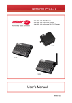
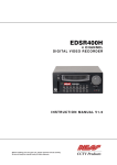
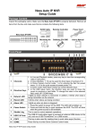
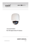
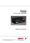
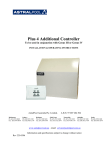
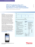
Ness 104-443 HD-SDI camera
User’s Manual
REV1.3 Nov11
www.ness.com.au
Head Office:
Ness Security Products Pty Ltd
ABN 28 069 984 372
Ph +61 2 8825 9222 Fax +61 2 9674 2520
[email protected]
Sydney
Ph 02 8825 9222 Fax 02 9674 2520
[email protected]
Melbourne
Ph 03 9875 6400 Fax 03 9875 6422
[email protected]
Brisbane
Ph 07 3399 4910 Fax 07 3217 9711
[email protected]
Perth
Ph 08 9328 2511 Fax 08 9227 7073
[email protected]
Adelaide
Ph 08 8152 0000 Fax 08 8152 0100
[email protected]
Copyright Notice
All rights reserved. No part of this publication may be reproduced, transmitted or stored in a retrieval system in any form or by any means,
electronic, mechanical, photocopying, recording, or otherwise, without the prior written permission of Ness.
Ness reserves the right to make changes to features and specifications at any time without prior notification in the interest of ongoing
product development and improvement.
© 2011 Ness Corporation Pty Ltd ABN 28 069 984 372
Table of Contents
1.
2.
Overview .................................................................................................................................. 2
1.1
Features ........................................................................................................................ 2
1.2
Package Contents ......................................................................................................... 3
1.3
Dimensions.................................................................................................................... 3
Camera Cabling....................................................................................................................... 4
2.1
Product Application ....................................................................................................... 4
2.2
Connectors .................................................................................................................... 5
2.3
TV System/Resolution/Frame Rate Setup .................................................................... 6
2.4
Lens Mounting............................................................................................................... 6
Appendix A: Technical Specifications.......................................................................................... 7
Appendix B: Back Focus Adjustment ........................................................................................... 8
1
1.
Overview
HD-CCTV standard offers a new opportunity for traditional CCTV surveillance
industry. It makes CCTV Camera transmit high definition image through coaxial
cable. Combing SDI standard with high quality SONY CMOS sensor, the SDI
Box Camera provides 1920x1080 resolution high quality image as well as easy
and low-cost installation. With innovative WDR function and digital noise
reduction technology, the SDI Box Camera can offer close-up images with
exceptional details even at night time.
1.1
Features
z
z
z
z
z
z
z
z
z
z
z
Progressive Scan CMOS Sensor
Full HD 1080P @ 30fps/60fps
HD 720P @ 30fps/60fps
Wide Dynamic Range
Digital Noise Reduction
Intuitive OSD Operation
BNC output support
DC12V Support
AC24V Support*
RS-485 Support*
Alarm I/O Support*
(*) Optional
2
1.2
Package Contents
Please check the box contains the items listed here. If any item is missing or
has defects, DO NOT install or operate the product and contact your dealer for
assistance.
SDI Box Camera
Back focus adjuster
CD
Quick Guide
(bundled software and documentation)
1.3
Dimensions
3
2.
Camera Cabling
Please follow the instructions below to complete SDI Box Camera cable
connections.
2.1
Product Application
Connect the SDI Box Camera to other devices as shown in the diagram to
complete a video surveillance solution.
4
2.2
Connectors
The diagram below shows the IP Camera’s reset button and various connectors.
Definition for each connector will be given as follows.
Single Board
Item
A
B
C
D
E
F
Dual Board
Definition
PWR
AUTO IRIS Connector
RESET
SDI OUTPUT
↑ / ↓ / ← / → / ENTER
Single Board
DC12V
Dual Board
DC12V/AC24V
G
H
VIDEO
DIP Switch
I
Alarm I/O
Remark
Power connection indication (green light)
Auto Iris Lens connector
Reset
SDI signal output
OSD control key
Power connector
+
AC 24V: AC_IN 1
DC 12V: DC12V
AC 24V: GND
DC 12V: GND
-
AC 24V: AC_IN 2
DC 12V: DC12V
BNC output
TV system/ Resolution/ Frame Rate Setup/ BNC
1
ALARM_GND
5
T2
ALARM_IN+
6
T+
3
ALARM_OUT7
R4
ALARM_OUT+
8
R+
5
2.3
TV System/Resolution/Frame Rate Setup
Please refer to the illustrations below to set up the Camera TV system,
resolution and frame rate.
Pin
Definition
1
2
3
4
5
6
TV System
Resolution
Frame Rate
Reserved
Reserved
BNC
Setting
ON
NTSC
720P
50/60
ON
OFF
PAL
1080P
25/30
OFF
Please kindly notice that while BNC output is on, there will be no SDI
signal.
2.4
Lens Mounting
If use C-Mount lens, after removing the camera’s plastic cover, users need to
mount the C/CS mount adapter to the camera. Then attach the lens onto the
C/CS mount adapter, as the illustrations shown below.
C/CS Mount Adapter
6
Completion
Appendix A: Technical Specifications
Camera
1/2.8” Sony Progressive CMOS
Sensor
2144 (H) x 1588 (V), 3.4M
Total Pixel
Shutter Speed
1/30 ~ 1/10000 sec.
A/D Converter
10 /12 bit
Lens
Fixed / Vari-focal
C/CS Mount Lens
Operation
1080P / 720P
Video Streaming
30/60 fps, 25/50 fps @1080P
Frame Rate
30/60 fps, 25/50 fps @ 720P
AE Mode
Back Light Compensation
White Balance
Image Setting
Auto / Shutter / IRIS / Manual
On / Off
Auto / Indoor / Outdoor / ATW / Manual
Digital Noise Reduction
On / Off
Wide Dynamic Range
On / Off
IR Function
Aperture
Privacy Mask
Auto / On / Off
1 ~ 16
16
Mechanical
C / CS Mount
Lens Mounting
Video Output
SDI
75 Ω
BNC
1.0 Vp-p / 75 Ω
Remote Control*
DIP Switch
Connectors
TACT Switch
Auto Iris
Alarm In/Out*
Up to 2 sets RS-485
6 pin
5 pin (OSD Control)
DC Drive
Up to 2 sets
General
Dimension
Weight
Power Source
Power Consumption
Regulatory
125 x 82 x 52 mm (L x W x H) (w/o Lens)
330 g (0.73 lbs)
DC 12V±10% / AC 24V*±10%
Max 5W
CE, FCC, RoHS
(*) Optional
7
Appendix B: Back Focus Adjustment
When to adjust back focus
Back Focus refers to the distance from the rear lens element to the camera focal plane. In
most cases, it is required to adjust back focus only when the camera’s lens cannot hold
focus throughout its zoom range.
What requirements
Tools required when carrying out back focus adjustment include:
1. Back focus adjuster (in the IP Camera’s package)
2. Test chart / contrasting object
How to adjust back focus
Step 1: Set the camera on a stable mount, with the test chart or object at least 75 feet (23
meters) away (or as far as possible).
Step 2: Make sure the iris is wide open. Therefore, it is advised to keep the environment
in low light condition.
Step 3: Adjust the focus to infinite far (∞).
Step 4: Turn the zoom to the extreme telephoto position, and then focus on the subject.
Step 5: Set the zoom to wide-angle position.
Step 6: Loosen the back focus ring’s retaining screw with the supplied adjuster, and
adjust the back focus ring for sharp picture.
Step 7: Repeat steps 3 ~ 6 until focus can stay the same throughout the zoom range.
Step 8: Tighten the back focus ring’s retaining screw to fix the ring.
8