1
USER MANUAL
FGEN-AIM
stations
with multi
FUNTIONALITY
Sense it! Connect it! Bus it! Solve it!
All brand and product names are trademarks or registered trade marks of the owner
concerned.
Edition 10/2013
© Hans Turck GmbH, Muelheim an der Ruhr
All rights reserved, including those of the translation.
No part of this manual may be reproduced in any form (printed, photocopy, microfilm or any
other process) or processed, duplicated or distributed by means of electronic systems without
written permission of Hans Turck GmbH & Co. KG, Muelheim an der Ruhr.
Subject to alterations without notice
Table of contents
1
About this manual
1.1
Documentation concept .................................................................................................................................1-2
1.2
Description of symbols used ..........................................................................................................................1-3
1.3
General .............................................................................................................................................................1-4
1.3.1
1.3.2
Prescribed use .........................................................................................................................................................................................1-4
Notes concerning planning/installation of this product .........................................................................................................1-4
1.4
List of revisions ................................................................................................................................................1-5
2
Multi-protocol functionality
2.1
General .............................................................................................................................................................2-2
2.1.1
Protocol dependent functions ..........................................................................................................................................................2-2
3
FGEN – general technical properties
3.1
General .............................................................................................................................................................3-2
3.2
General information on FGEN ........................................................................................................................3-3
3.3
General technical data ....................................................................................................................................3-4
3.3.1
3.3.2
3.3.3
Technical data..........................................................................................................................................................................................3-4
Dimension drawings .............................................................................................................................................................................3-5
LED-displays .............................................................................................................................................................................................3-5
3.4
Connection possibilities..................................................................................................................................3-6
3.4.1
3.4.2
3.4.3
Ethernet .....................................................................................................................................................................................................3-6
Operating/load voltage .......................................................................................................................................................................3-6
Analog inputs and outputs.................................................................................................................................................................3-7
3.5
Address assignment ........................................................................................................................................3-8
3.5.1
3.5.2
3.5.3
3.5.4
3.5.5
3.5.6
3.5.7
3.5.8
3.5.9
3.5.10
Default setting of the gateway..........................................................................................................................................................3-8
Resetting the IP-address, switch position "000"..........................................................................................................................3-8
Address setting via the rotary-mode ..............................................................................................................................................3-9
Address setting via the mode BootP...............................................................................................................................................3-9
Address setting via the mode DHCP ............................................................................................................................................ 3-10
Address setting via mode PGM ...................................................................................................................................................... 3-10
Addressing via mode PGM-DHCP ................................................................................................................................................. 3-11
F_Reset (Factory Reset) ..................................................................................................................................................................... 3-11
Addressing via I/O-ASSISTANT 3 (FDT/DTM)............................................................................................................................. 3-12
Addressing via PGM-DHCP .............................................................................................................................................................. 3-15
3.6
SET-button .................................................................................................................................................... 3-15
3.7
Device configuration files............................................................................................................................ 3-15
3.8
Web server - remote access/configuration................................................................................................. 3-16
3.8.1
3.8.2
3.8.3
3.8.4
3.8.5
3.8.6
IP address ............................................................................................................................................................................................... 3-16
Access rights ......................................................................................................................................................................................... 3-17
Login / password ................................................................................................................................................................................. 3-17
Network Configuration ..................................................................................................................................................................... 3-18
Station Configuration ........................................................................................................................................................................ 3-19
Station Diagnostics............................................................................................................................................................................. 3-19
D301271 1013 - FGEN - multi protocol
i
3.8.7
3.8.8
3.8.9
3.8.10
Ethernet Statistics ................................................................................................................................................................................3-19
Links..........................................................................................................................................................................................................3-19
Change Admin Password..................................................................................................................................................................3-20
Parameters .............................................................................................................................................................................................3-21
3.9
Status and Control Word of the FGEN-stations .......................................................................................... 3-22
3.9.1
3.9.2
Status Word............................................................................................................................................................................................3-22
Control Word.........................................................................................................................................................................................3-22
4
Digital inputs FGEN-IM16-x001
4.1
FGEN-IM16-x001 ............................................................................................................................................. 4-2
4.1.1
4.1.2
4.1.3
4.1.4
Technical data ......................................................................................................................................................................................... 4-2
Wiring diagrams ..................................................................................................................................................................................... 4-2
Parameters ............................................................................................................................................................................................... 4-3
Diagnostic message of I/O-channels .............................................................................................................................................. 4-3
5
Digital outputs FGEN-OM16-x001
5.1
FGEN-OM16-x001 ........................................................................................................................................... 5-2
5.1.1
5.1.2
5.1.3
5.1.4
Technical data ......................................................................................................................................................................................... 5-2
Wiring diagrams ..................................................................................................................................................................................... 5-2
Parameters ............................................................................................................................................................................................... 5-3
Diagnostic messages............................................................................................................................................................................ 5-3
6
Digital in-/outputs FGEN-IOM88-x001, FGEN-XSG16-x001
6.1
FGEN-IOM88-x001 .......................................................................................................................................... 6-2
6.1.1
6.1.2
6.1.3
6.1.4
Technical data ......................................................................................................................................................................................... 6-2
Wiring diagrams ..................................................................................................................................................................................... 6-3
Parameters ............................................................................................................................................................................................... 6-3
Diagnostic messages............................................................................................................................................................................ 6-4
6.2
FGEN-XSG16-000x .......................................................................................................................................... 6-5
6.2.1
6.2.2
6.2.3
6.2.4
Technical data ......................................................................................................................................................................................... 6-5
Wiring diagrams ..................................................................................................................................................................................... 6-6
Parameters ............................................................................................................................................................................................... 6-7
Diagnostic messages............................................................................................................................................................................ 6-8
7
Implementation of EtherNet/IP™
7.1
EtherNet/IP Communications Profile ............................................................................................................ 7-2
7.1.1
7.1.2
7.1.3
I/O Messages ........................................................................................................................................................................................... 7-2
Explicit Messages ................................................................................................................................................................................... 7-2
Communications profile of FGEN .................................................................................................................................................... 7-2
7.2
QC - QuickConnect .......................................................................................................................................... 7-4
7.2.1
7.2.2
General ...................................................................................................................................................................................................... 7-4
QuickConnect in FGEN......................................................................................................................................................................... 7-4
7.3
Classes and Instances of the EtherNet/IP™-stations .................................................................................... 7-6
7.3.1
7.3.2
7.3.3
7.3.4
7.3.5
EtherNet/IP™ Standard Classes ......................................................................................................................................................... 7-6
Identity Object (0×01) .......................................................................................................................................................................... 7-7
Assembly Object (0×04) ...................................................................................................................................................................... 7-9
Connection Manager Object (0×06) .............................................................................................................................................7-21
TCP/IP Interface Object (0×F5)........................................................................................................................................................7-22
ii
D301271 1013 - FGEN - multi protocol
7.3.6
Ethernet Link Object (0×F6)............................................................................................................................................................. 7-26
7.4
VSC-Vendor Specific Classes........................................................................................................................ 7-28
7.4.1
7.4.2
7.4.3
7.4.4
7.4.5
Class instance of the VSC.................................................................................................................................................................. 7-28
Gateway Class (VSC 100)................................................................................................................................................................... 7-29
Process Data Class (VSC102)............................................................................................................................................................ 7-31
Digital Versatile Module Class (VSC117) ..................................................................................................................................... 7-34
Miscellaneous Parameters Class (VSC 126) ................................................................................................................................ 7-35
7.5
Diagnostic messages via process data........................................................................................................ 7-36
7.5.1
7.5.2
Summarized Diagnostics.................................................................................................................................................................. 7-36
Scheduled Diagnostics (manufacturer specific diagnosis) .................................................................................................. 7-36
8
Application example: FGEN for EtherNet/IP™ with Allen Bradley PLC and RS Logix 5000
8.1
General .............................................................................................................................................................8-2
8.1.1
Used hard-/ software.............................................................................................................................................................................8-2
8.2
Network configuration....................................................................................................................................8-3
8.2.1
8.2.2
Configuration of the network in "RS Logix 5000" .......................................................................................................................8-3
Downloading the I/O configuration................................................................................................................................................8-8
8.3
I/O data mapping.......................................................................................................................................... 8-10
8.4
Process data access ...................................................................................................................................... 8-11
8.4.1
8.4.2
Setting outputs .................................................................................................................................................................................... 8-11
Example program................................................................................................................................................................................ 8-11
8.5
Activating QuickConnect ............................................................................................................................ 8-13
9
Implementation of Modbus TCP
9.1
Common Modbus description ........................................................................................................................9-2
9.1.1
9.1.2
Protocol description..............................................................................................................................................................................9-3
Data model ...............................................................................................................................................................................................9-4
9.2
Implemented Modbus functions....................................................................................................................9-6
9.3
Modbus registers.............................................................................................................................................9-7
9.3.1
9.3.2
9.3.3
9.3.4
9.3.5
9.3.6
9.3.7
Data width of the I/O-modules in the modbus-register area.............................................................................................. 9-10
Register mapping of the FGEN-stations...................................................................................................................................... 9-11
Register 100Ch: "Station status"..................................................................................................................................................... 9-16
Register 1130h: „Modbus-Connection-Mode“.......................................................................................................................... 9-17
Register 1131h: „Modbus-Connection-Timeout“ .................................................................................................................... 9-17
Register 0×113C und 0×113D: „Restore Modbus-Connection-Parameters” ................................................................. 9-17
Register 0×113E und 0×113F: „Save Modbus-Connection-Parameters“ ........................................................................ 9-18
9.4
Bit areas: mapping of input-discrete- and coil-areas ................................................................................ 9-19
9.5
Error behavior of outputs (watchdog) ........................................................................................................ 9-20
9.6
Parameters and diagnostic messages of the I/O channels ....................................................................... 9-21
10
Application example FGEN for Modbus TCP with CODESYS Win V3
10.1
Used hard-/ software.................................................................................................................................... 10-2
10.1.1 Hardware ................................................................................................................................................................................................ 10-2
10.1.2 Software.................................................................................................................................................................................................. 10-2
D301271 1013 - FGEN - multi protocol
iii
10.2
Network configuration ................................................................................................................................. 10-3
10.3
Programming with CODESYS....................................................................................................................... 10-4
10.3.1
10.3.2
10.3.3
10.3.4
10.3.5
10.3.6
10.3.7
10.3.8
10.3.9
10.3.10
10.3.11
10.3.12
Predefined feature sets......................................................................................................................................................................10-4
Creating a new project ......................................................................................................................................................................10-5
Defining the communication settings .........................................................................................................................................10-7
Adding the Ethernet Adapter..........................................................................................................................................................10-9
Adding the Modbus master .......................................................................................................................................................... 10-10
Adding a Modbus TCP slave ......................................................................................................................................................... 10-11
Programming (example program) ............................................................................................................................................. 10-13
CODESYS: Global variables............................................................................................................................................................ 10-14
Modbus channels.............................................................................................................................................................................. 10-15
Building, login and start ................................................................................................................................................................. 10-23
Reading out the process data ...................................................................................................................................................... 10-25
Evaluation of the status word of FGEN-XSG16-5001 (%IW1) ............................................................................................ 10-26
11
Implementation of PROFINET
11.1
FSU - Fast Start-Up (prioritized startup)..................................................................................................... 11-2
11.1.1 General ....................................................................................................................................................................................................11-2
11.1.2 FSU in FGEN ...........................................................................................................................................................................................11-2
11.2
GSDML-file..................................................................................................................................................... 11-3
11.3
PROFINET-Error Codes.................................................................................................................................. 11-4
11.4
Parameters .................................................................................................................................................... 11-5
11.4.1 General module parameters - parameters for slot 0 (turck-fgen) ......................................................................................11-5
11.4.2 Parameters for I/O channels ...........................................................................................................................................................11-5
11.5
Description of user data for acyclic services............................................................................................... 11-7
11.5.1 Description of the acyclic gateway user data............................................................................................................................11-7
11.5.2 Description of the acyclic I/O-channel user data .....................................................................................................................11-8
12
Application example: FGEN for PROFINET with a Siemens S7
12.1
Application example .................................................................................................................................... 12-2
12.1.1
12.1.2
12.1.3
12.1.4
12.1.5
12.1.6
12.1.7
12.1.8
12.1.9
12.1.10
12.1.11
12.1.12
General ....................................................................................................................................................................................................12-2
Example network .................................................................................................................................................................................12-2
New project in the Simatic Manager ............................................................................................................................................12-3
Setting the PG/PC-interface.............................................................................................................................................................12-3
Installation of the GSDML-files........................................................................................................................................................12-4
Adding PROFINET network nodes .................................................................................................................................................12-7
Scanning the network for PROFINET nodes............................................................................................................................ 12-10
Name assignment for FGEN-stations......................................................................................................................................... 12-11
PROFINET-neighborhood detection (LLDP)............................................................................................................................ 12-12
Online topology detection............................................................................................................................................................ 12-15
Fast Start-Up - configuration of fieldbus nodes .................................................................................................................... 12-16
Diagnostics with Step 7 .................................................................................................................................................................. 12-18
13
Guidelines for Electrical Installation
13.1
General notes ................................................................................................................................................ 13-2
13.1.1 General ....................................................................................................................................................................................................13-2
13.1.2 Cable routing.........................................................................................................................................................................................13-2
13.1.3 Lightning protection ..........................................................................................................................................................................13-3
iv
D301271 1013 - FGEN - multi protocol
13.1.4 Transmission media............................................................................................................................................................................ 13-3
13.2
Potential relationships................................................................................................................................. 13-4
13.3
Electromagnetic compatibility(EMC ........................................................................................................... 13-5
13.3.1 Ensuring electromagnetic compatibility .................................................................................................................................... 13-5
13.3.2 Grounding of inactive metal components................................................................................................................................. 13-5
13.3.3 PE connection....................................................................................................................................................................................... 13-5
13.4
Shielding of cables ....................................................................................................................................... 13-6
13.5
Potential compensation............................................................................................................................... 13-7
13.5.1 Switching inductive loads ................................................................................................................................................................ 13-7
13.5.2 Protection against Electrostatic Discharge (ESD) .................................................................................................................... 13-7
14
Appendix
14.1
Changing the IP address of a PC/ network interface card ......................................................................... 14-2
14.1.1 Changing the IP address in Windows .......................................................................................................................................... 14-2
14.1.2 Changing the IP address via I/O-ASSISTANT V3 ....................................................................................................................... 14-4
14.2
Deactivating/ adapting the firewall in Windows ....................................................................................... 14-5
14.2.1 Addressing via DHCP ......................................................................................................................................................................... 14-7
15
Glossary
16
Index
D301271 1013 - FGEN - multi protocol
v
vi
D301271 1013 - FGEN - multi protocol
1
About this manual
1.1
Documentation concept ............................................................................................................................ 1-2
1.2
Description of symbols used ..................................................................................................................... 1-3
1.3
General........................................................................................................................................................ 1-4
1.3.1
1.3.2
Prescribed use ...................................................................................................................................................................................1-4
Notes concerning planning/installation of this product ...................................................................................................1-4
1.4
List of revisions........................................................................................................................................... 1-5
D301271 1013 - FGEN - multi protocol
1-1
About this manual
1.1
Documentation concept
This manual contains all information about the TURCK FGEN-product line in protection class IP67 with
multi-protocol function.
The following chapters contain:
the general technical data and station properties,
a description of the function and the assembly of the single devices in the product line,
a description of the stations' representation in the different Ethernet-protocols,
a description of the devices' handling in the different PLC-applications,
1-2
D301271 1013 - FGEN - multi protocol
Description of symbols used
1.2
Description of symbols used
Warning
This sign can be found next to all notes that indicate a source of hazards. This can refer to
danger to personnel or damage to the system (hardware and software) and to the facility.
This sign means for the operator: work with extreme caution.
Attention
This sign can be found next to all notes that indicate a potential hazard.
This can refer to possible danger to personnel and damages to the system (hardware and
software) and to the facility.
Note
This sign can be found next to all general notes that supply important information about one
or more operating steps.
These specific notes are intended to make operation easier and avoid unnecessary work due
to incorrect operation.
D301271 1013 - FGEN - multi protocol
1-3
About this manual
1.3
General
Attention
Please read this section carefully. Safety aspects cannot be left to chance when dealing with
electrical equipment.
This manual includes all information necessary for the prescribed use of the FGEN-stations. It has been
specially conceived for personnel with the necessary qualifications.
1.3.1
Prescribed use
Warning
The devices described in this manual must be used only in applications prescribed in this
manual or in the respective technical descriptions, and only with certified components and
devices from third party manufacturers.
Appropriate transport, storage, deployment and mounting as well as careful operating and thorough
maintenance guarantee the trouble-free and safe operation of these devices.
1.3.2
Notes concerning planning/installation of this product
Warning
All respective safety measures and accident protection guidelines must be considered
carefully and without exception.
1-4
D301271 1013 - FGEN - multi protocol
List of revisions
1.4
List of revisions
In comparison to the previous manual edition, the following changes/ revisions have been made:
Table 1-1:
List of revisions
Chapter
Subject
new
changed
3
Web server - remote access/configuration (page 3-16)
x
5
Changes in th technical data of module, page 5-2
x
6
Changes in th technical data of module, page 6-2 and page
6-5
x
7
EtherNet/IP Communications Profile (page 7-2)
x
Note
The publication of this manual renders all previous editions invalid.
D301271 1013 - FGEN - multi protocol
1-5
About this manual
1-6
D301271 1013 - FGEN - multi protocol
2
Multi-protocol functionality
2.1
General........................................................................................................................................... 2-2
2.1.1
Protocol dependent functions ....................................................................................................................................................2-2
– PROFINET ........................................................................................................................................................................................2-2
– EtherNet/IP™ ..................................................................................................................................................................................2-2
D301271 1013 - FGEN - multi protocol
2-1
Multi-protocol functionality
2.1
General
The compact I/O-stations of the product line FGEN combine the three Ethernet protocols EtherNet/IP™,
Modbus TCP and PROFINET in one device.
A multi-protocol device can be operated without intervention of the user (which means, without
changes in the parameterization) in all of the three Ethernet protocols mentioned.
During the start-up after a power-on, the module runs in "snooping" mode and detects the Ethernet
protocol which requests a link connection by listening the traffic.
If a protocol is detected, the device automatically changes to the detected protocol and ignores the
telegrams of the other two.
2.1.1
Protocol dependent functions
PROFINET
Fast Start-UP (FSU)
Topology discovery
Address assignment via LLDP
EtherNet/IP™
QuickConnect (QC), see page 8-13
DLR (Device Level Ring)
2-2
D301271 1013 - FGEN - multi protocol
3
FGEN – general technical properties
3.1
General........................................................................................................................................................ 3-2
3.2
General information on FGEN ................................................................................................................... 3-3
3.3
General technical data ............................................................................................................................... 3-4
3.3.1
3.3.2
3.3.3
Technical data ...................................................................................................................................................................................3-4
Dimension drawings .......................................................................................................................................................................3-5
LED-displays .......................................................................................................................................................................................3-5
3.4
Connection possibilities ............................................................................................................................ 3-6
3.4.1
3.4.3
Ethernet ...............................................................................................................................................................................................3-6
– Ethernet-connection in QC-/FSU-applications..................................................................................................................3-6
Operating/load voltage .................................................................................................................................................................3-6
– Voltage supply via 7/8’’, 5-pole (FGEN-xxxxx-5xx1).........................................................................................................3-7
– Voltage supply via 7/8’’, 4-pole (FGEN-xxxxx-4xx1).........................................................................................................3-7
Analog inputs and outputs...........................................................................................................................................................3-7
3.5
Address assignment................................................................................................................................... 3-8
3.5.1
3.5.2
3.5.3
3.5.4
3.5.5
3.5.6
3.5.7
3.5.8
3.5.9
3.5.10
Default setting of the gateway....................................................................................................................................................3-8
Resetting the IP-address, switch position "000"....................................................................................................................3-8
Address setting via the rotary-mode ........................................................................................................................................3-9
Address setting via the mode BootP.........................................................................................................................................3-9
Address setting via the mode DHCP ...................................................................................................................................... 3-10
Address setting via mode PGM................................................................................................................................................ 3-10
Addressing via mode PGM-DHCP ........................................................................................................................................... 3-11
– PROFINET ..................................................................................................................................................................................... 3-11
F_Reset (Factory Reset) ............................................................................................................................................................... 3-11
Addressing via I/O-ASSISTANT 3 (FDT/DTM)....................................................................................................................... 3-12
Addressing via PGM-DHCP ........................................................................................................................................................ 3-15
3.6
SET-button ................................................................................................................................................3-15
3.7
Device configuration files........................................................................................................................3-15
3.8
Web server - remote access/configuration ............................................................................................3-16
3.8.1
3.8.2
3.8.3
3.8.4
3.8.5
3.8.6
3.8.7
3.8.8
3.8.9
3.8.10
IP address ......................................................................................................................................................................................... 3-16
Access rights ................................................................................................................................................................................... 3-17
Login / password........................................................................................................................................................................... 3-17
Network Configuration ............................................................................................................................................................... 3-18
Station Configuration .................................................................................................................................................................. 3-19
Station Diagnostics....................................................................................................................................................................... 3-19
Ethernet Statistics ......................................................................................................................................................................... 3-19
Links ................................................................................................................................................................................................... 3-19
Change Admin Password ........................................................................................................................................................... 3-20
Parameters....................................................................................................................................................................................... 3-21
3.9
Status and Control Word of the FGEN-stations .....................................................................................3-22
3.9.1
Status Word..................................................................................................................................................................................... 3-22
– Meaning of the status bits ..................................................................................................................................................... 3-22
Control Word .................................................................................................................................................................................. 3-22
3.4.2
3.9.2
D301271 1013 - FGEN - multi protocol
3-1
FGEN – general technical properties
3.1
General
This chapter contains all information about the hardware of the FGEN-stations, the general technical
data as well as the connection possibilities, the addressing,etc..
Note
Station-specific information can be found in the single station descriptions within the
respective chapters of this manual.
3-2
D301271 1013 - FGEN - multi protocol
General information on FGEN
3.2
General information on FGEN
The FGEN product family offers the following approved features:
direct connection of up to 16 digital in- and outputs to an Ethernet-network
Protocols: EtherNet/IP™, Modbus TCP and PROFINET RT in one single device
channel-related short-circuit diagnosis of outputs and slot-related short-circuit diagnosis of inputs
Ethernet-connection with two 4-pole, d-coded M12 x 1 round connectors
integrated Ethernet-switch for building up a line-topology
D301271 1013 - FGEN - multi protocol
3-3
FGEN – general technical properties
3.3
3.3.1
General technical data
Technical data
Table 3-1:
Technical data
of the FGENstations
Power supply
Operating voltage UB (VI)
18 to 30 VDC
Load voltage UL (VO)
18 to 30 VDC
Internal current consumption (from UB)
< 200 mA
Connectors
Ethernet
2 x M12-female (OUT), 4-pole, D-coded
Power supply
FGEN-xxxx-5001
7/8" connector, 5-pole
FGEN-xxxx-4001
7/8" connector, 4-pole
Inputs / Outputs
M12 female, 5-pole
Isolation voltages
UBL (UB against UL)
none
UETH (supply voltage against Ethernet)
500 V AC
UETHETH (ETH1 against ETH 2)
500 V AC
Housing
Fibre-glass reinforced Polyamide (PA6-GF30)
Size
60.4 × 220.5 × 27 mm (B × L × H)
Mounting
via 4 through-holes, Ø 4.4 mm
Mounting distance
station to station
≥ 50 mm
Valid for operation in the ambient temperatures
mentioned below, with sufficient ventilation as well
as maximum load (horizontal mounting).
In case of low simultaneity factors and low ambient
temperatures, mounting distances of < 50 mm may
be possible.
Protection class
IP67
Vibration test
to EN 60068-2-6, IEC 68-2-47
Shock test
acc. to EN 60068-2-27
EMC
acc. to EN 61131-2
Temperature range
– operating
0 °C to 55 °C (32 °F to 131 °F)
– Storage and transport temperature range -25 °C to 70 °C (-13 °F to 158 °F)
3-4
D301271 1013 - FGEN - multi protocol
General technical data
3.3.2
Dimension drawings
Figure 3-1:
Dimensions for
the FGENstations
27
13
13
C2
C3
C10
C1
C0 C8
1
0
6
5
4
Ui
2
7
1
0
9
3
ETH1
2 3
8 7
2 3
8 7
Bus
1
0
9
Power
4
5
6
60,4 42
4
5
6
1
0
9
2 3
8 7
4
5
6
C7
220,5
3.3.3
C6 C5
210,5
Uo
ETH2
C11
5,4
C4 C9
LED-displays
Table 3-2:
Dimensions for
the FGENstations
LED
Display
Meaning
ETHx
green
Link established,100 Mbps
green, flashing
Ethernet traffic (100 Mbps)
yellow
Link established,10 Mbps
yellow flashing
Ethernet traffic (10 Mbps)
off
No Ethernet link.
Check the Ethernetconnection.
off
UB < 18 V DC
Check the connected
operating voltage.
green
UB and UL in the operating range
red
UL < 18 V DC
green
24 V at input/ output
red
Overcurrent at the output or at
the sensor supply
green
Active connection to a master
-
green, flashing
ready for operation
-
red
IP address conflict or restore
mode
Check the IP-addresses in
the network or wait until the
device is ready.
red, flashing
Blink-/wink-command active
-
red/green
Autonegotiation and / or
waiting for DHCP- / BootPaddress assignment.
Power
Ix/Ox
BUS
D301271 1013 - FGEN - multi protocol
Remedy
Check the load voltage.
3-5
FGEN – general technical properties
3.4
3.4.1
Connection possibilities
Ethernet
The connection to Ethernet via the integrated auto-crossing switch is done using two 4-pole, D-coded
M12 x 1-Ethernet-female connectors.
Figure 3-2:
Female connectors M12 x 1
Pin assignment
ETH2
of the M12 x 1- ETH1
female connectors, 4-pole
v
v
2
1
4
1 = TD
2 = RD
3 3 = TD
4 = RD
+ (YE)
+ (WH)
(OG) 1
(BU)
C10
2
3
4
C11
Ethernet-connection in QC-/FSU-applications
Note
Please observe the following for QuickConnect (QC)- and Fast Start-Up (FSU)-applications:
– do not use a crossover-cable
– ETH1 = connector for incoming Ethernet-line
– ETH2 = connector for outgoing Ethernet-line
3.4.2
Operating/load voltage
The power supply is realized via 7/8" connectors on the module.
These connectors are designed either 4- or 5-pole.
Figure 3-3:
Power supply
UI = voltage IN
UO = voltage OUT for supplying the next node
Ui
Uo
Power
0
4
Note
The operation voltage (UB) and the load voltage (UL) are fed and monitored separately. If the
voltage falls below the permissible voltage, the outputs are switched off.
UL can be switched off. In this case, the module still communicates and the inputs are still read
in.
In case of an undervoltage at UL, the "POWER" LED changes from green to red. In case of an
undervoltage at UB, the "POWER" LED is turned off.
3-6
D301271 1013 - FGEN - multi protocol
Connection possibilities
Voltage supply via 7/8’’, 5-pole (FGEN-xxxxx-5xx1)
Figure 3-4:
7/8’’ male and
female,
5-pole
w
4
3
5
v
2
1
1 = GNDL
2 = GNDB
3 = PE
4 = UB
5 = UL
2
3
1
w
4
5
4
5
UL and UB galvanically isolated.
3
v
2
1
1 = GND L
2 = GND B
3 = FE
PE
4 = UB
5 = UL
2
1
3
4
5
No galvanic isolation of UL and UB at the
FGEN-XSG16-5001
Voltage supply via 7/8’’, 4-pole (FGEN-xxxxx-4xx1)
Figure 3-5:
7/8’’ male and
female, 4-pole
w
1
21
2
3
43
4
1 = UL
21==UAux
B +
E+
32==GND-B
E
43==GND-L
4 = Aux
v
3
43
4
UL and UB galvanically isolated.
3.4.3
1
21
2
w
U
1
1
2
2
v
3
3
4
4
1 = UL
1=
=U
Aux
2
B +
2=
= GND
E+
3
3=
= GND
E
4
4 = Aux
3
3
4
4
1
1
2
2
No galvanic isolation of UL and UB at the
FGEN-XSG16-4001!
Analog inputs and outputs
The module is equipped throughout with metal M12 connectors for connection of the sensor/actuator
level.
Note
For the pin assignment of the M12-connectors, please refer to the wiring diagrams in the
station-specific chapters of this manual.
D301271 1013 - FGEN - multi protocol
3-7
FGEN – general technical properties
3.5
Address assignment
Setting the address mode is done through the 3 rotary coding-switches on the gateway.
Figure 3-6:
Decimal rotary
coding-switches
for address
setting
9 0 1
9 0 1
9 0 1
8
2
8
2
8
7
3
7
3
7
6 5 4
6 5 4
3
6 5 4
x1
x 10
x 100
2
000: 192.168.1.254
1 - 254: static rotary
300: BootP
400: DHCP
500: PGM
600: PGM-DHCP
900: F_Reset
Attention
The cover of the decimal rotary coding-switches must be closed by tightening the screw after
use.
The seal in the cover must not be damaged or slipped.
The protection class IP67 can only be guaranteed when the cover is closed correctly.
Note
After every change of the address-mode, a reset must be carried out.
3.5.1
Default setting of the gateway
The stations' default-settings are as follows:
IP-address
subnet mask
default gateway
192.168.1.254
255.255.255.0
192.168.1.1
Note
The stations can be reset by the user to these default settings at any time.
To reset the module, set the three coding-switches on the gateway to "000" followed by a
power-on reset.
3.5.2
Resetting the IP-address, switch position "000"
By setting the rotary coding switches to "000" followed by a voltage reset, the module is set to the
address 192.168.1.254 for IP-based services (seeDefault setting of the gateway (page 3-8)).
The I/O-ASSISTANT can, for example, communicate with the station in this switch position.
Note
Setting "000" is no operation mode! Please set the device to another mode after having
reset the IP address to the default values.
3-8
D301271 1013 - FGEN - multi protocol
Address assignment
3.5.3
Address setting via the rotary-mode
switch position: 001 - 254
When using the rotary-mode, the last byte of the station’s IP address can be set via the rotary coding
switches.
Addresses in the range from 0 to 255 can be allocated, whereas 1 is normally reserved for the defaultgateway. 0 and 255 are reserved for broadcast messages in the subnet.
Note
We therefore recommend addresses in the range of 2-254.
3.5.4
Address setting via the mode BootP
switch position: 300
Address setting is carried out by a BootP-server in the network after the start-up of the gateway.
Note
The IP address, as well as the default subnet mask assigned to the station by the BootP-server,
are stored in the station’s EEPROM.
If the station is subsequently switched to rotary- or PGM-mode, the settings carried out via
BootP (IP address, subnet mask, etc) will be read from the module’s EEPROM.
PROFINET
Please assure, that in PROFINET -applications, the address assigned via a BootP-server corresponds to
the address, which is assigned in the configuration tool.
D301271 1013 - FGEN - multi protocol
3-9
FGEN – general technical properties
3.5.5
Address setting via the mode DHCP
switch position: 400
Address setting is carried out by a BootP-server in the network after the start-up of the gateway.
Note
The IP address, as well as the default subnet mask assigned to the station by the DHCP-server,
are stored in the station’s EEPROM.
If the station is subsequently switched to rotary- or PGM-mode, the settings carried out via
BootP (IP address, subnet mask, etc) will be read from the module’s EEPROM.
DHCP supports three mechanisms for IP address allocation:
In "automatic allocation", the DHCP-server assigns a permanent IP address to a client.
In "dynamic allocation", DHCP assigns an IP address to a client for a limited period of time. After this
time, or until the client explicitly relinquishes the address, the address can be re-assigned.
In "manual allocation", a client's IP address is assigned by the network administrator, and DHCP is
used simply to convey the assigned address to the client.
PROFINET
Please assure, that in PROFINET -applications, the address assigned via a BootP-server corresponds to
the address, which is assigned in the configuration tool.
3.5.6
Address setting via mode PGM
switch position: 500
The PGM-mode enables access of the software I/O-ASSISTANT to the module’s network settings.
Note
In the PGM-mode, all network settings (IP address, subnet mask, etc.) are send to the module’s
internal EEPROM and stored permanently.
3-10
D301271 1013 - FGEN - multi protocol
Address assignment
3.5.7
Addressing via mode PGM-DHCP
switch position: 600
The device sends DHCP-requests until a IP-address is assigned (DHCP-server, PROFINET-controller).
The assigned IP-address is stored to the device and the DCHP-client is stopped.
Even after a restart of the device, the device sends no further DHCP-requests.
PROFINET
This mode assures a PROFINET-compliant operation of the modules.
Note
If a DHCP-server is used within the network, problems may occur during IP-assignment.
In this case, both, the DHCP-server as well as the PROFINET-controller (vie DCP), try an IPaddress-assignment.
3.5.8
F_Reset (Factory Reset)
switch position: 900
Setting 900 sets all device-settings back to the default values and deletes all data in the device's internal
flash.
Note
Setting 900 is no operation mode! Please set the device to another mode after having reset
the IP address to the default values.
D301271 1013 - FGEN - multi protocol
3-11
FGEN – general technical properties
3.5.9
Addressing via I/O-ASSISTANT 3 (FDT/DTM)
The software-tool I/O-ASSISTANT enables direct access to the Ethernet-network via the Ethernet cable.
The IP address, as well as the subnet mask of the TURCK Ethernet stations, can be changed according
to the application by using the Busaddress Management function of the BL Service Ethernet interface
(TCP/IP) in the software I/O-ASSISTANT.
Figure 3-7:
BL Service
Ethernet
3-12
D301271 1013 - FGEN - multi protocol
Address assignment
Figure 3-8:
Busaddress
management
Figure 3-9:
Searching
networkNodes in the
Busaddress
management
A
A Search function
in the Busaddress management
D301271 1013 - FGEN - multi protocol
3-13
FGEN – general technical properties
Note
The access of the IO-ASSISTANT to the station is only possible, if the station already has an IPaddress and if it is operated in switch position 500 = PGM or 600 = PGM-DHCP-mode (see also
Address assignment (page 3-8)).
Note
When using Windows XP as operating system, difficulties may occur with system-integrated
firewall.
It may inhibit the access of PACTware™ (I/O-ASSISTANT V3) to the Ethernet-network. In this
case, please adapt your firewall respectively or deactivate it.
Figure 3-10:
Specify IP
address
change
3-14
D301271 1013 - FGEN - multi protocol
SET-button
3.5.10
Addressing via PGM-DHCP
The device's network settings can be changed under "Network Configuration" only by users having
administrator rights.
Further information concerning the web server of the FGEN-devices and it's use can be found under
Web server - remote access/configuration (page 3-16).
Note
The access of the IO-ASSISTANT to the station is only possible, if the station already has an IPaddress and if it is operated in switch position 500 = PGM or 600 = PGM-DHCP-mode (see also
Address assignment (page 3-8)).
Figure 3-11:
Web server with
Network
Configuration
3.6
SET-button
Pushing the SET-button causes a device-restart.
3.7
Device configuration files
The actual device configuration files for the stations can be downloaded from the TURCK-home page
www.turck.com.
D301271 1013 - FGEN - multi protocol
3-15
FGEN – general technical properties
3.8
Web server - remote access/configuration
Note
When working with the webserver of the module, it should be assured, that the browser
always reloads the HTML-pages from the module‘s webserver (forced reload). The data
should not be loaded from the browser‘s cache memory.
This guarantees that the data to be shown are always acutal (module type, module status
etc.).
Short-cuts for browser:
Internet Explorer: Shift + F5
Mozilla Firefox:
Ctrl + F5
Figure 3-12:
Web server of
the FGENstation
3.8.1
IP address
Open the web server by entering the device's IP-address in your web browser.
IF no IP-address is assigned to the device (DHCP-, BootP-server etc.), then the web server can be opened
using the default IP-address 192.168.1.254.
3-16
D301271 1013 - FGEN - multi protocol
Web server - remote access/configuration
3.8.2
Access rights
Without administrator rights, data as general product data and diagnosis data are read only.
In order to achieve administrator rights, please log-on to the web server, see Login / password (page
3-17).
3.8.3
Login / password
Login to the web server by using the default-password "password".
The default-password can be changed by the administrator at every time under Change Admin
Password (page 3-20) .
Note
A reset of the device to the default-settings using the switch position
900 "F_Reset" also causes a reset of the password to "password".
Figure 3-13:
Web server
"Home" screen
D301271 1013 - FGEN - multi protocol
3-17
FGEN – general technical properties
3.8.4
Network Configuration
On the "Network Configuration"-page, network-relevant settings can be changed.
Figure 3-14:
Web server
"Network
Configuration"
3-18
D301271 1013 - FGEN - multi protocol
Web server - remote access/configuration
3.8.5
Station Configuration
The "Station Configuration"-page serves for parameterizing the device's fieldbus interface.
Figure 3-15:
Web server
"Station
Configuration"
3.8.6
Station Diagnostics
Diagnostic messages of the device are displayed on the "Station Diagnostics"-page.
3.8.7
Ethernet Statistics
The page "Ethernet Statistics" shows information like the port-status, telegram and error counters etc.
The page can above all be useful for analyzing network problems.
3.8.8
Links
This page contains for example a link to the product page on the TURCK-homepage.
D301271 1013 - FGEN - multi protocol
3-19
FGEN – general technical properties
3.8.9
Change Admin Password
Please define an individual password for administrator rights.
Default-password: „password“
Note
A reset of the device to the default-settings using the switch position
900 "F_Reset" also causes a reset of the password to "password".
Figure 3-16:
Change Admin
Password
3-20
D301271 1013 - FGEN - multi protocol
Web server - remote access/configuration
3.8.10
Parameters
The "Parameters"-page is used to parameterize the station's I/O-channels.
Figure 3-17:
Web server
"Parameters"
D301271 1013 - FGEN - multi protocol
3-21
FGEN – general technical properties
3.9
Status and Control Word of the FGEN-stations
The Status as well as the Control Word are mapped into the station's process data.
EtherNet/IP™
In EtherNet/IP™, the mapping can be disabled, see Gateway Class (VSC 100), GW Status register
(page 7-30) and GW Control Register (page 7-30).
Modbus TCP
→ see Register 100Ch: "Station status" (page 9-16)
PROFINET
→ see PROFINET-Error Codes (page 11-4)
3.9.1
Status Word
Byte
Status
0
Bit 7
Bit 6
Bit 5
Bit 4
Bit 3
Bit 2
Bit 1
UL
-
-
-
-
-
-
Diag
Warn
-
FCE
-
-
CFG
COM
UB
-
1
Bit 0
Meaning of the status bits
Table 3-3:
Meaning of the
status bits
3.9.2
Name
Meaning
DiagWarn
Summarized diagnosis of the device. At least 1 channel sends diagnostics.
UL
Load voltage not within the permissible range (18 to 30 V)
UB
System voltage not within the permissible range (18 to 30 V)
COM
I/O Communication Lost Error
No Communication on the module bus.
CFG
I/O CfgModified Error
The I/O-configuration has be changed and is no longer compatible.
FCE
Force Mode Active Error
The Force Mode is activated, which means, the actual output values may no match the
ones defined and sent by the field bus.
Control Word
The Control Word has no function at the moment, it is reserves for further use.
3-22
D301271 1013 - FGEN - multi protocol
4
Digital inputs FGEN-IM16-x001
4.1
FGEN-IM16-x001 ........................................................................................................................................ 4-2
4.1.1
4.1.2
Technical data ...................................................................................................................................................................................4-2
Wiring diagrams ...............................................................................................................................................................................4-2
– Ethernet ...........................................................................................................................................................................................4-2
– Power supply .................................................................................................................................................................................4-2
– Input M12x1 ...................................................................................................................................................................................4-2
Parameters..........................................................................................................................................................................................4-3
Diagnostic message of I/O-channels.........................................................................................................................................4-3
4.1.3
4.1.4
D301271 1013 - FGEN - multi protocol
4-1
Digital inputs FGEN-IM16-x001
4.1
FGEN-IM16-x001
The station offers 16 digital inputs for 3-wire pnp sensors.
4.1.1
Technical data
Table 4-1:
Technical data
FGEN-IM16x0001
Type designation
FGEN-IM16-x001
Number of channels
(16) 3-wire pnp-sensors
Supply (via UB)
18 ... 30 VDC from operating voltage
Supply current
< 120 mA per connector, short-circuit protected
Switching threshold OFF/ON
2 mA / 4 mA
Low level signal voltage
-3 to 5 VDC (EN 61131-2, type 1 and 3)
High level signal voltage
11 to 30 VDC (EN 61131-2, type 1 and 3)
Max. input current
6 mA
Switch-on delay
2.5 ms
Switching frequency
≥ 500 Hz
Potential isolation
galvanic isolation against UL and Ethernet
Note
General technical data for the products of the FGEN-product line can be found in chapter 3.
4.1.2
Wiring diagrams
Ethernet
→ Ethernet (page 3-6)
Power supply
→ Operating/load voltage (page 3-6)
Input M12x1
Figure 4-1:
Wiring diagram,
input M12x1
3 BU
5 PE
4 BK
1 BN +
2 WH
3 BU
v
C0...C7
4-2
D301271 1013 - FGEN - multi protocol
FGEN-IM16-x001
4.1.3
Parameters
Table 4-2:
Parameters
Parameter name Value
A default
setting
Digital input
(Inv. DIx)
Description
0 = normal A
1 = inverted
Inverts the digital input signal.
Further information about the parameter data mapping can be found in the fieldbus specific chapters.
EtherNet/IP™: chapter 7.4.4, Digital Versatile Module Class (VSC117) (page 7-34) ff.
Modbus TCP: chapter 9.3.2, Register mapping of the FGEN-stations (page 9-11) ff.
PROFINET: chapter 11.4, Parameters (page 11-5)
4.1.4
Diagnostic message of I/O-channels
Table 4-3:
Diagnostic
messages
Diagnostics Description
SCSx
Short circuit at sensor supply of the respective channel
Further information about the diagnostic data mapping can be found in the fieldbus specific chapters.
EtherNet/IP™: chapter 7.4.4, Process Data Class (VSC102) (page 7-31)
Modbus TCP: chapter 9.3.2, Register mapping of the FGEN-stations (page 9-11) ff.
PROFINET: chapter 11.3, PROFINET-Error Codes (page 11-4)
D301271 1013 - FGEN - multi protocol
4-3
Digital inputs FGEN-IM16-x001
4-4
D301271 1013 - FGEN - multi protocol
5
Digital outputs FGEN-OM16-x001
5.1
FGEN-OM16-x001....................................................................................................................................... 5-2
5.1.1
5.1.2
Technical data ...................................................................................................................................................................................5-2
Wiring diagrams ...............................................................................................................................................................................5-2
– Ethernet ...........................................................................................................................................................................................5-2
– Power supply .................................................................................................................................................................................5-2
– Input M12x1 ...................................................................................................................................................................................5-2
Parameters..........................................................................................................................................................................................5-3
Diagnostic messages ......................................................................................................................................................................5-3
5.1.3
5.1.4
D301271 1013 - FGEN - multi protocol
5-1
Digital outputs FGEN-OM16-x001
5.1
FGEN-OM16-x001
The station offers 16 digital inputs for DC actuators.
5.1.1
Technical data
Table 5-1:
Technical data
FGEN-OM16x001
Type designation
FGEN-OM16-x001
Number of channels
(16) DC actuators
Output voltage
18…30 V DC from load voltage
Output current per channel
2.0 A, short-circuit proof
Load type
resistive, inductive, lamp load
Simultaneity factor
0.25 for complete module,
1 × 2 A or 2 × 1 A per connector,
but only max. 9 A total current per module
Potential isolation
galvanic isolation against UB and Ethernet
Note
General technical data for the products of the FGEN-product line can be found in chapter 3.
5.1.2
Wiring diagrams
Ethernet
→ Ethernet (page 3-6)
Power supply
→ Operating/load voltage (page 3-6)
Input M12x1
Figure 5-1:
Wiring diagram,
output M12x1
5 PE
4 BK +
1
2 WH +
3 BU
v
C0...C7
5-2
D301271 1013 - FGEN - multi protocol
FGEN-OM16-x001
5.1.3
Parameters
Table 5-2:
Parameters
Parameter name Value
Description
A default
setting
Output on
overcurrent
(SROx)
0 = activated A
The output switches on automatically after an overload.
1 = deactivated
The output is switched-off after an overload until a new setcommand is given (fall and rise).
Further information about the parameters can be found in the fieldbus specific chapters.
EtherNet/IP™: chapter 7.4.4, Digital Versatile Module Class (VSC117) (page 7-34) ff.
Modbus TCP: chapter 9.3.2, Register mapping of the FGEN-stations (page 9-11) ff.
PROFINET: chapter 11.4, Parameters (page 11-5)
5.1.4
Diagnostic messages
Table 5-3:
Diagnostic
messages
Diagnostics Description
SCOx
Short circuit at output of the respective channel
Further information about the diagnostic data mapping can be found in the fieldbus specific chapters.
EtherNet/IP™: chapter 7.4.3, Process Data Class (VSC102) (page 7-31) ff.
Modbus TCP: chapter 9.3.2, Register mapping of the FGEN-stations (page 9-11) ff.
PROFINET: chapter 11.3, PROFINET-Error Codes (page 11-4)
D301271 1013 - FGEN - multi protocol
5-3
Digital outputs FGEN-OM16-x001
5-4
D301271 1013 - FGEN - multi protocol
6
Digital in-/outputs FGEN-IOM88-x001, FGEN-XSG16-x001
6.1
FGEN-IOM88-x001...................................................................................................................................... 6-2
6.1.1
6.1.2
6.1.3
6.1.4
Technical data ...................................................................................................................................................................................6-2
Wiring diagrams ...............................................................................................................................................................................6-3
– Ethernet ...........................................................................................................................................................................................6-3
– Power supply .................................................................................................................................................................................6-3
Parameters..........................................................................................................................................................................................6-3
Diagnostic messages ......................................................................................................................................................................6-4
6.2
FGEN-XSG16-000x...................................................................................................................................... 6-5
6.2.1
6.2.2
Technical data ...................................................................................................................................................................................6-5
Wiring diagrams ...............................................................................................................................................................................6-6
– Ethernet ...........................................................................................................................................................................................6-6
– Power supply .................................................................................................................................................................................6-6
Parameters..........................................................................................................................................................................................6-7
Diagnostic messages ......................................................................................................................................................................6-8
6.2.3
6.2.4
D301271 1013 - FGEN - multi protocol
6-1
Digital in-/outputs FGEN-IOM88-x001, FGEN-XSG16-x001
6.1
FGEN-IOM88-x001
The station offers 8 digital inputs for 3-wire pnp sensors and 8 digital outputs for DC actuators.
6.1.1
Technical data
Table 6-1:
Technical data
FGEN-IOM88x001
Designation
FGEN-IOM88-x001
Inputs
(8) 3-wire pnp-sensors
Supply (via UB)
18... 30 V DC from operating voltage
Supply current
< 120 mA per connector, short-circuit protected
Switching threshold OFF/ON
2 mA / 4 mA
Low level signal voltage
-3 to 5 VDC (EN 61131-2, type 1 and 3)
High level signal voltage
11 to 30 VDC (EN 61131-2, type 1 and 3)
Max. input current
6 mA
Switch-on delay
2.5 ms
Switching frequency
≥ 500 Hz
Potential isolation
galvanic isolation against UL and Ethernet
Outputs
(8) DC actuators
Output voltage
18…30 V DC from load voltage
Output current per channel
2.0 A, short-circuit proof
Load type
resistive, inductive, lamp load
Simultaneity factor
0.25 for complete module,
1 × 2 A or 2 × 1 A per connector,
but only max. 9 A total current per module
Potential isolation
galvanic isolation against UB and Ethernet
Note
General technical data for the products of the FGEN-product line can be found in chapter 3.
6-2
D301271 1013 - FGEN - multi protocol
FGEN-IOM88-x001
6.1.2
Wiring diagrams
Ethernet
→ Ethernet (page 3-6)
Power supply
→ Operating/load voltage (page 3-6)
Figure 6-1:
Wiring diagram
input M12 x 1
3 BU
4 BK
5 PE
1 BN +
2 WH
3 BU
v
C0...C3
Figure 6-2:
Wiring diagram
output M12 x 1
5 PE
4 BK +
1
2 WH +
3 BU
v
C4...C7
6.1.3
Parameters
Table 6-2:
Parameters
Parameter name Value
Description
A default
setting
Digital input
(Inv. DIx)
0 = normal A
1 = inverted
Inverts the digital input signal.
Output on
overcurrent
(SROx)
0 = activated A
The output switches on automatically after an overload.
1 = deactivated
The output is manually switched-off after an overload.until
a new set-command is given (rise and fall).
Further information about the parameter data mapping can be found in the fieldbus specific chapters.
EtherNet/IP™: chapter 7.4.4, Digital Versatile Module Class (VSC117) (page 7-34) ff.
Modbus TCP: chapter 9.3.2, Register mapping of the FGEN-stations (page 9-11) ff.
PROFINET: chapter 11.4, Parameters (page 11-5)
D301271 1013 - FGEN - multi protocol
6-3
Digital in-/outputs FGEN-IOM88-x001, FGEN-XSG16-x001
6.1.4
Diagnostic messages
Table 6-3:
Diagnostic
messages
Diagnostics Description
SCSx
Short circuit at sensor supply of the respective channel
SCOx
Short circuit at output of the respective channel
Further information about the diagnostic data mapping can be found in the fieldbus specific chapters.
EtherNet/IP™: chapter 7.3.3, Process data mapping FGEN-IM16-x001 (page 7-11) ff.
Modbus TCP: chapter 9.3.2, Register mapping of the FGEN-stations (page 9-11) ff.
PROFINET: chapter 11.3, PROFINET-Error Codes (page 11-4)
6-4
D301271 1013 - FGEN - multi protocol
FGEN-XSG16-000x
6.2
FGEN-XSG16-000x
The station is equipped with 16 channels, which can be configured individually, depending on the
specific application requirements. Up to sixteen 3 wire pnp sensors or sixteen DC actuators with a
maximum output current of 1.4 A per output can be connected.
6.2.1
Technical data
Table 6-4:
Technical data
FGEN-XSG16x00x
Designation
FGEN-XSG16-x001
Inputs
(16) 3-wire pnp-sensors
Supply (via UB)
18 ... 30 V DC from operating voltage
Supply current
< 120 mA per connector, short-circuit protected
Switching threshold OFF/ON
2 mA / 4 mA
Low level signal voltage
-3 to 5 VDC (EN 61131-2, type 1 and 3)
High level signal voltage
11 to 30 VDC (EN 61131-2, type 1 and 3)
Max. input current
6 mA
Switch-on delay
2.5 ms
Switching frequency
≥ 500 Hz
Potential isolation
galvanic isolation against UL and Ethernet
Outputs
(16) DC actuators
Output voltage
18…30 V DC from load voltage
Output current per channel
2.0 A, short-circuit proof
Load type
resistive, inductive, lamp load
Simultaneity factor
0.25 for complete module,
1 × 2 A or 2 × 1 A per connector,
but only max. 9 A total current per module
Potential isolation
galvanic isolation against UB and Ethernet
Note
General technical data for the products of the FGEN-product line can be found in chapter 3.
D301271 1013 - FGEN - multi protocol
6-5
Digital in-/outputs FGEN-IOM88-x001, FGEN-XSG16-x001
6.2.2
Wiring diagrams
Ethernet
→ Ethernet (page 3-6)
Power supply
→ Operating/load voltage (page 3-6)
Figure 6-3:
Wiring
diagrams
Connection of 2 actuators:
5 PE
4 BK +
1
2 WH +
3 BU –
Connection of 2 sensors:
3 BU –
5 PE
4 BK
1 BN +
2 WH
3 BU –
Combination of sensor and actuator:
3 () BU
5
PE
4 ( ) BK
1 (+) BN
2
3 () BU
5
PE
4 (+) BK
1 (+) BN
2 ( ) WH
6-6
D301271 1013 - FGEN - multi protocol
FGEN-XSG16-000x
6.2.3
Parameters
Table 6-5:
Parameters
Parameter name Value
Description
A default
setting
Digital input
(Inv. DI)
0 = normal A
1 = inverted
Inverts the digital input signal.
Output on
overcurrent
(SROx)
0 = activated A
The output switches on automatically after an overload.
1 = deactivated
The output is manually switched-off after an overload.until
a new set-command is given (rise and fall).
output
0 = deactivated
1 = activated A
Further information about the parameter data mapping can be found in the fieldbus specific chapters.
EtherNet/IP™: chapter 7.3.3, Process data mapping FGEN-XSG16-x001 (page 7-17) ff.
Modbus TCP: chapter 9.3.2, Register mapping of the FGEN-stations (page 9-11) ff.
PROFINET: chapter 11.4, Parameters (page 11-5)
D301271 1013 - FGEN - multi protocol
6-7
Digital in-/outputs FGEN-IOM88-x001, FGEN-XSG16-x001
6.2.4
Diagnostic messages
Table 6-6:
Diagnostic
messages
Diagnostics Description
SCSx
Short circuit at sensor supply of the respective channel
SCOx
Short circuit at output of the respective channel
Further information about the diagnostic data mapping can be found in the fieldbus specific chapters.
EtherNet/IP™: chapter 7.3.3, Process data mapping FGEN-IM16-x001 (page 7-11) ff.
Modbus TCP: chapter 9.3.2, Register mapping of the FGEN-stations (page 9-11) ff.
PROFINET: chapter 11.3, PROFINET-Error Codes (page 11-4)
6-8
D301271 1013 - FGEN - multi protocol
7
Implementation of EtherNet/IP™
7.1
EtherNet/IP Communications Profile ....................................................................................................... 7-2
7.1.1
7.1.2
7.1.3
I/O Messages......................................................................................................................................................................................7-2
Explicit Messages..............................................................................................................................................................................7-2
Communications profile of FGEN...............................................................................................................................................7-2
– Unicast .............................................................................................................................................................................................7-2
– Multicast ..........................................................................................................................................................................................7-2
– COS I/O Connection ....................................................................................................................................................................7-3
– Cyclic I/O Connection .................................................................................................................................................................7-3
– UCMM...............................................................................................................................................................................................7-3
– Connected Explicit Messaging ................................................................................................................................................7-3
7.2
QC - QuickConnect ..................................................................................................................................... 7-4
7.2.1
7.2.2
General.................................................................................................................................................................................................7-4
QuickConnect in FGEN ...................................................................................................................................................................7-4
– QuickConnect via Configuration Assembly........................................................................................................................7-5
– Quick Connect via Class Instance Attribute........................................................................................................................7-5
7.3
Classes and Instances of the EtherNet/IP™-stations................................................................................ 7-6
7.3.1
7.3.2
7.3.3
7.3.4
7.3.5
7.3.6
EtherNet/IP™ Standard Classes ...................................................................................................................................................7-6
PROFINETIdentity Object (0×01) ................................................................................................................................................7-7
Assembly Object (0×04).................................................................................................................................................................7-9
– Configuration Assembly ............................................................................................................................................................7-9
– Process data instances ............................................................................................................................................................ 7-10
– Process data mapping FGEN-IM16-x001 .......................................................................................................................... 7-11
– Process data mapping FGEN-OM16-x001........................................................................................................................ 7-13
– Process data mapping FGEN-IOM88-x001....................................................................................................................... 7-15
– Process data mapping FGEN-XSG16-x001....................................................................................................................... 7-17
– Meaning of Process data bits................................................................................................................................................ 7-20
Connection Manager Object (0×06)....................................................................................................................................... 7-21
TCP/IP Interface Object (0×F5) ................................................................................................................................................. 7-22
Ethernet Link Object (0×F6) ...................................................................................................................................................... 7-26
7.4
VSC-Vendor Specific Classes ...................................................................................................................7-28
7.4.1
7.4.2
Class instance of the VSC............................................................................................................................................................ 7-28
Gateway Class (VSC 100)............................................................................................................................................................. 7-29
– Class instance ............................................................................................................................................................................. 7-29
– Object Instance 1....................................................................................................................................................................... 7-29
– Object Instance 2....................................................................................................................................................................... 7-30
Process Data Class (VSC102)...................................................................................................................................................... 7-31
– Class instance ............................................................................................................................................................................. 7-31
– Object instance 1, standard input process data (compressed) ............................................................................... 7-31
– Object Instance 3, diagnostic instance ............................................................................................................................. 7-32
– Object Instance 4, COS/CYCLIC instance.......................................................................................................................... 7-33
Digital Versatile Module Class (VSC117) ............................................................................................................................... 7-34
– Object Instance .......................................................................................................................................................................... 7-34
Miscellaneous Parameters Class (VSC 126) .......................................................................................................................... 7-35
– Instance 1 / Instance 2............................................................................................................................................................. 7-35
7.4.3
7.4.4
7.4.5
7.5
Diagnostic messages via process data ...................................................................................................7-36
7.5.1
7.5.2
Summarized Diagnostics............................................................................................................................................................ 7-36
Scheduled Diagnostics (manufacturer specific diagnosis) ............................................................................................ 7-36
D301271 1013 - FGEN - multi protocol
7-1
Implementation of EtherNet/IP™
7.1
EtherNet/IP Communications Profile
EtherNet/IP is based on a connection-oriented communication model. This means that it is only
possible to exchange data via specified connections assigned to the devices.
Communication between the nodes in the EtherNet/IP network can be carried out either via I/O
Messages or Explicit Messages.
7.1.1
I/O Messages
I/O Messages serve to exchange high priority process and application data over the network.
Communication between the slaves in the EtherNet/IP network is carried out according to the Server/
Client Model,
which means a producing application transmits data to another or a number of consuming
applications. It is quite possible that information is passed to a number of Application Objects in a
single device.
7.1.2
Explicit Messages
Explicit Messages are used to transmit low-priority configuration data, general management data or
diagnostic data between two specific devices. This is a point-to-point connection in a Server/Client
System that requires a request from a client always to be confirmed by a response from the server.
Message Router Request
Consists of a service code, path size value, a message router path and service data. An EPATH is used
in the message router path to indicate the target object.
Message Router Response
Consists of a service field with the most significant bit set. This is an echo of the service code in the
request message with the most significant bit set. A reserved byte follows the service code, which is
followed by the General Status code.
7.1.3
Communications profile of FGEN
FGEN behaves as an EtherNet/IP Server in the network; the scanner of the higher-level controller
operates as a EtherNet/IP Client.
The following EtherNet/IP communications types are supported:
Unicast
Multicast
Cyclic Connection
Unconnected (UCMM) Explicit Messaging
Connected Explicit Messaging
Unicast
A point-to-point connection that exists between two nodes only.
Multicast
A packet with a special destination address, which multiple nodes on the network may be willing to
receive.
7-2
D301271 1013 - FGEN - multi protocol
EtherNet/IP Communications Profile
COS I/O Connection
COS (Change Of State) I/O Connections establish event-controlled connections. This means that the
EtherNet/IP devices generate messages as soon as a change of status occurs.
Cyclic I/O Connection
Messages are triggered time-controlled in Cyclic I/O connections by means of a time generator.
UCMM
The EtherNet/IP gateway offers the option of establishing explicit messaging via the UCMM port
(Unconnected Message Manager Port).
UCMM-based explicit messaging is normally used for random, non-periodic requests.
It is not recommended for frequent messaging because the UCMM input queue in a product is typically
limited to just a few messages. Once this limit is reached, subsequent requests are ignored and must
be retried.
Connected Explicit Messaging
CIP is a connection-based system. For most communications between nodes, a connection is used.
A connection is a path or a virtual circuit between two or more end points in a system. The purpose is
to transfer data in the most efficient manner possible.
The Connection ID is a number that is associated with a communication relationship. Receiving nodes
decode this key to know whether they must accept the data or not.
D301271 1013 - FGEN - multi protocol
7-3
Implementation of EtherNet/IP™
7.2
7.2.1
QC - QuickConnect
General
QuickConnect enables a PLC to build up connections to EtherNet/IP™-nodes in less than 300 ms after
switching-on the power supply for the EtherNet/IP™-network. This fast start up of devices is above all
necessary for robotic tool changes for example in the automobile industry.
Note
For correct cabling with FGEN in QC-applications, see Ethernet-connection in QC-/FSUapplications (page 3-6).
7.2.2
QuickConnect in FGEN
TURCK FGEN-stations support QuickConnect.
QuickConnect is activated:
via the configuration data in the PLC-program per
Assembly Class 0×04, Configuration Assembly 106, bit 9 = 1
(see also chapter 8, Activating QuickConnect (page 8-13)
or
via Class Instance Attribute in
TCP/IP Interface Object (0×F5), instance 1, attribute 12 (0×C0)
Note
Activating the QuickConnect-function leads to the automatical setting of all necessary portproperties:
7-4
Autonegotiation
= deactivated
transmission speed
= 100BaseT
Duplex
= full duplex
Topology
= linear
AutoMDIX
= deactivated
D301271 1013 - FGEN - multi protocol
QC - QuickConnect
QuickConnect via Configuration Assembly
The Configuration Assembly is part of the Assembly Class of the device and is defined during the
station's configuration in the RS Logix-software by Rockwell Automation.
Figure 7-1:
Configuration
Assembly
Note
Further information about the configuration of FGEN-stations in the Rockwell software
RS Logix can be found in chapter 8, Application example: FGEN for EtherNet/IP™ with
Allen Bradley PLC and RS Logix 5000.
Quick Connect via Class Instance Attribute
Activate QuickConnect via Class Instance Attribute using the following setting:
Class
Instance
Attribute
Value
245
(0xF5)
1
(0x01)
12
(0x0C)
0: disabled (default)
1: enabled
D301271 1013 - FGEN - multi protocol
7-5
Implementation of EtherNet/IP™
7.3
Classes and Instances of the EtherNet/IP™-stations
7.3.1
EtherNet/IP™ Standard Classes
The FGEN stations support the following EtherNet/IP™ Standard Classes in accordance with the CIP
specification.
Table 7-1:
EtherNet/IP™
Standard Classes
7-6
Class Code
Object name
01 (0×01)
Identity Object (0×01)
04 (0×04)
Assembly Object (0×04)
06 (0×06)
Connection Manager Object (0×06)
245 (0×F5)
TCP/IP Interface Object (0×F5)
246 (0×F6)
Ethernet Link Object (0×F6)
D301271 1013 - FGEN - multi protocol
Classes and Instances of the EtherNet/IP™-stations
7.3.2
Identity Object (0×01)
The following description of the Ethernet Link Object is taken from the CIP specification, Vol. 2, Rev. 2.1
by ODVA & ControlNet International Ltd. and adapted to FGEN.
Class Attributes
Table 7-2:
Attr. No.
Attribute name
Get/
Set
Type
Value
1 (0×01)
REVISION
G
UINT
1
2 (0×02)
MAX OBJECT INSTANCE
G
UINT
1
6 (0×06)
MAX CLASS ATTRIBUTE
G
UINT
7
7 (0×07)
MAX INSTANCE ATTRIBUTE
G
UINT
7
Class Attributes
Instance attributes
Table 7-3:
Attr. No.
Attribute name
Get/ Type
Set
Description
1 (0×01)
VENDOR
G
UINT
Contains the vendor ID.
TURCK = 48
2 (0×02)
PRODUCT TYPE
G
UINT
Indicates the general type of product.
Communications Adapter
12dez = 0×0C
3 (0×03)
PRODUCT CODE
G
UINT
Identifies a particular product within a device
type.
Default: 27247dec = 6A6F
4 (0×04)
REVISION
G
STRUCT
OF:
USINT
USINT
Revision of the item the Identity Object is
representing.
0x01
0x06
Instance
attributes
Major Minor
5 (0×05)
DEVICE STATUS
G
WORD
See Table 7-4: Device Status
6 (0×06)
SERIAL NUMBER
G
UDINT
Contains the ident-no. of the product (3 last
bytes of the MAC-ID).
7 (0×07)
PRODUCT NAME
G
STRUCT
OF:
e. g.:
FGEN-XSG16-5001
LENGTH
NAME
D301271 1013 - FGEN - multi protocol
USINT
STRING
[13]
7-7
Implementation of EtherNet/IP™
Device Status
Table 7-4:
Device Status
Bit
Name
Definition
0 to 1
reserved
Default = 0
2
Configured
TRUE = 1
→ The application of the device has been configured
(≠ default-settings).
3
reserved
Default = 0
4 to 7
Extended Device
Status
0011 = no I/O connection established
0110 = At least one I/O connection in run mode
0111 = At least one I/O connection established, all in IDLE
mode
All other settings = reserved
8 to 15
reserved
Default = 0
Common services
Table 7-5:
Common services
7-8
Service code
Class
Instance
Service name
01 (0x01)
yes
yes
Get_Attribute_All
Returns a predefined list of the object‘s attributes.
05 (0x05)
no
yes
Reset
Starts the reset service for the device.
14 (0x0E)
yes
yes
Get_Attribute_Single
Returns the contents of a specified attribute.
16 (0x10)
no
no
Set_Attribute_Single
Modifies a single attribute.
D301271 1013 - FGEN - multi protocol
Classes and Instances of the EtherNet/IP™-stations
7.3.3
Assembly Object (0×04)
Assembly Objects bind attributes of multiple objects to allow data to or from each object to be sent or
received over a single connection.
The following description of the Ethernet Link Object is taken from the CIP specification, Vol. 2, Rev. 2.1
by ODVA & ControlNet International Ltd. and adapted to FGEN.
Class attributes
Table 7-6:
Attr. No.
Attribute name
Get/
Set
Type
Value
1 (0×01)
REVISION
G
UINT
2
2 (0×02)
MAX OBJECT INSTANCE
G
UINT
104
Class attributes
Instance attributes
Table 7-7:
Attr. No.
Attribute name
Get/ Type
Set
3 (0×03)
DATA
S
ARRAY OF
BYTE
4 (0×04)
SIZE
G
UINT
Instance
attributes
Description
UINT Number of bytes in attr. 3
256 or variable
Common services
Table 7-8:
Common services
Service code
Class
Instance
Service name
01 (0x01)
yes
yes
Get_Attribute_All
14 (0x0E)
no
yes
Get_Attribute_Single
Configuration Assembly
Instance 106
14 byte configuration data
Byte 9, bit 1 is used to activate QuickConnect in the station (see also QuickConnect via Configuration
Assembly (page 7-5)).
D301271 1013 - FGEN - multi protocol
7-9
Implementation of EtherNet/IP™
Process data instances
Instance 101
Contains the station’s input data (static length 256 bytes).
2 Bytes status information (see page 3-22)
+ process data
Instance 102
Contains the station’s output data (static length 256 bytes).
2 Bytes Control data (mapped, but not defined)
+ process data
Instance 103 und Instance 104
In- and output assembly instances with variable assembly sizes. The assembly size is pre-calculated to
support the stations I/O-configuration, enabled diagnostics, etc.
input assembly instance: 103
output assembly instance: 104
The effective size of the Assembly Instance can be determined using the Assembly Object (instance
0×67, attribute 0x04) and can be from 2 to 496 bytes large.
7-10
D301271 1013 - FGEN - multi protocol
Classes and Instances of the EtherNet/IP™-stations
Process data mapping FGEN-IM16-x001
No diagnostic message,
Status- and control-word can be deactivated, see page 3-22.
IN =
OUT =
4 Byte
2 Byte
IN
Byte
Status
0
Inputs
Bit 7
Bit 6
Bit 5
Bit 4
Bit 3
Bit 2
Bit 1
-
-
-
-
-
-
-
Diag
Warn
1
-
FCE
-
-
CFG
COM
UB
-
2
DI7
C3P2
DI6
C3P4
DI5
C0P2
DI4
C2P4
DI3
C1P2
DI2
C1P4
DI1
C0P2
DI0
C0P4
3
DI15
C7P2
DI14
C7P4
DI13
C6P2
DI12
C6P4
DI11
C5P2
DI10
C5P4
DI9
C4P2
DI8
C4P4
OUT
Byte
Bit 7
Bit 6
Bit 5
Bit 4
Bit 3
Control
0
Control word (MSB)
1
Control word (LSB)
Bit 0
Bit 2
Bit 1
Bit 0
Bit 0
→ Meaning of Process data bits (page 7-20)
Summarized diagnostics activated, see page 7-36
IN =
OUT =
6 Byte
2 Byte
IN
Byte
Bit 7
Bit 6
Bit 5
Bit 4
Bit 3
Bit 2
Bit 1
Status
0
-
-
-
-
-
-
-
Diag
Warn
1
-
FCE
-
-
CFG
COM
UB
-
2
DI7
C3P2
DI6
C3P4
DI5
C0P2
DI4
C2P4
DI3
C1P2
DI2
C1P4
DI1
C0P2
DI0
C0P4
3
DI15
C7P2
DI14
C7P4
DI13
C6P2
DI12
C6P4
DI11
C5P2
DI10
C5P4
DI9
C4P2
DI8
C4P4
Diagnos
tics
4
-
-
-
-
-
-
-
I/O Diag
5
-
-
-
-
-
-
-
-
OUT
Byte
Bit 7
Bit 6
Bit 5
Bit 4
Bit 3
Bit 2
Bit 1
Bit 0
Control
0
Control word (MSB)
1
Control word (LSB)
Inputs
→ Meaning of Process data bits (page 7-20)
D301271 1013 - FGEN - multi protocol
7-11
Implementation of EtherNet/IP™
Manufacturer specific (scheduled diagnostics) activated, see page 7-36
IN =
OUT =
8 Byte
2 Byte
IN
Byte
Status
0
Inputs
Diagnos
tics
Bit 7
Bit 6
Bit 5
Bit 4
Bit 3
Bit 2
Bit 1
-
-
-
-
-
-
-
Diag
Warn
1
-
FCE
-
-
CFG
COM
UB
-
2
DI7
C3P2
DI6
C3P4
DI5
C0P2
DI4
C2P4
DI3
C1P2
DI2
C1P4
DI1
C0P2
DI0
C0P4
3
DI15
C7P2
DI14
C7P4
DI13
C6P2
DI12
C6P4
DI11
C5P2
DI10
C5P4
DI9
C4P2
DI8
C4P4
4
-
-
-
-
-
-
-
I/O Diag
-
-
Sched
Diag
-
-
-
-
-
6
SCS7
SCS6
SCS5
SCS4
SCS3
SCS2
SCS1
SCS0
7
-
-
-
-
-
-
-
-
Bit 7
Bit 6
Bit 5
Bit 4
Bit 3
Bit 2
Bit 1
Bit 0
5
OUT
Byte
Control
0
Control word (MSB)
1
Control word (LSB)
Bit 0
→ Meaning of Process data bits (page 7-20)
7-12
D301271 1013 - FGEN - multi protocol
Classes and Instances of the EtherNet/IP™-stations
Process data mapping FGEN-OM16-x001
No diagnostic message,
Status- and control-word can be deactivated, see page 3-22.
IN =
OUT =
2 Byte
4 Byte
IN
Byte
Status
0
Bit 7
Bit 6
Bit 5
Bit 4
Bit 3
Bit 2
Bit 1
UL
-
-
-
-
-
-
Diag
Warn
-
FCE
-
-
CFG
COM
UB
-
Bit 5
Bit 4
Bit 1
Bit 0
1
OUT
Byte
Control
0
Control word (MSB)
1
Control word (LSB)
Outputs
Bit 7
Bit 6
Bit 3
Bit 2
Bit 0
2
DO7
C3P2
DO6
C3P4
DO5
C2P2
DO4
C2P4
DO3
C1P2
DO2
C1P4
DO1
C0P2
DO0
C0P4
3
DO15
C7P2
DO14
C7P4
DO13
C6P2
DO12
C6P4
DO11
C5P2
DO10
C5P4
DO9
C4P2
DO8
C4P4
→ Meaning of Process data bits (page 7-20)
Summarized diagnostics activated, see page 7-36
IN =
OUT =
4 Byte
4 Byte
IN
Byte
Bit 7
Bit 6
Bit 5
Bit 4
Bit 3
Bit 2
Bit 1
Status
0
UL
-
-
-
-
-
-
Diag
Warn
1
-
FCE
-
-
CFG
COM
UB
-
Diagnos
tics
4
-
-
-
-
-
-
-
I/O Diag
5
-
-
-
-
-
-
-
-
OUT
Byte
Bit 7
Bit 6
Bit 5
Bit 4
Bit 3
Bit 2
Bit 1
Bit 0
Control
0
Control word (MSB)
1
Control word (LSB)
Outputs
Bit 0
2
DO7
C3P2
DO6
C3P4
DO5
C2P2
DO4
C2P4
DO3
C1P2
DO2
C1P4
DO1
C0P2
DO0
C0P4
3
DO15
C7P2
DO14
C7P4
DO13
C6P2
DO12
C6P4
DO11
C5P2
DO10
C5P4
DO9
C4P2
DO8
C4P4
→ Meaning of Process data bits (page 7-20)
D301271 1013 - FGEN - multi protocol
7-13
Implementation of EtherNet/IP™
Manufacturer specific (scheduled diagnostics) activated, see page 7-36
IN =
OUT =
8 Byte
4 Byte
IN
Byte
Status
0
Diagnos
tics
Bit 7
Bit 6
Bit 5
Bit 4
Bit 3
Bit 2
Bit 1
UL
-
-
-
-
-
-
Diag
Warn
1
-
FCE
-
-
CFG
COM
UB
-
2
-
-
-
-
-
-
-
I/O Diag
-
-
Sched
Diag
-
-
-
-
-
3
4
-
-
-
-
-
-
-
5
SCO7
SCO6
SCO5
SCO4
SCO3
SCO2
SCO1
SCO0
6
SCO15
SCO14
SCO13
SCO12
SCO11
SCO10
SCO9
SCO8
7
-
-
-
-
-
-
-
-
Bit 7
Bit 6
Bit 5
Bit 4
Bit 3
Bit 2
Bit 1
Bit 0
OUT
Byte
Control
0
Control word (MSB)
1
Control word (LSB)
Outputs
-
Bit 0
2
DO7
C3P2
DO6
C3P4
DO5
C2P2
DO4
C2P4
DO3
C1P2
DO2
C1P4
DO1
C0P2
DO0
C0P4
3
DO15
C7P2
DO14
C7P4
DO13
C6P2
DO12
C6P4
DO11
C5P2
DO10
C5P4
DO9
C4P2
DO8
C4P4
→ Meaning of Process data bits (page 7-20)
7-14
D301271 1013 - FGEN - multi protocol
Classes and Instances of the EtherNet/IP™-stations
Process data mapping FGEN-IOM88-x001
No diagnostic message,
Status- and control-word can be deactivated, see page 3-22.
IN =
OUT =
4 Byte
4 Byte
IN
Byte
Status
0
Inputs
Bit 7
Bit 6
Bit 5
Bit 4
Bit 3
Bit 2
Bit 1
UL
-
-
-
-
-
-
Diag
Warn
1
-
FCE
-
-
CFG
COM
UB
-
2
DI7
C3P2
DI6
C3P4
DI5
C2P2
DI4
C2P4
DI3
C1P2
DI2
C1P4
DI1
C0P2
DI0
C0P4
3
-
-
-
-
-
-
-
-
Bit 7
Bit 6
Bit 5
Bit 4
Bit 3
Bit 2
Bit 1
Bit 0
OUT
Byte
Control
0
Control word (MSB)
1
Control word (LSB)
Outputs
Bit 0
2
DO7
C3P2
DO6
C3P4
DO5
C2P2
DO4
C2P4
DO3
C1P2
DO2
C1P4
DO1
C0P2
DO0
C0P4
3
-
-
-
-
-
-
-
-
Bit 0
→ Meaning of Process data bits (page 7-20)
Summarized diagnostics activated, see page 7-36
IN =
OUT =
6 Byte
4 Byte
IN
Byte
Bit 7
Bit 6
Bit 5
Bit 4
Bit 3
Bit 2
Bit 1
Status
0
UL
-
-
-
-
-
-
Diag
Warn
1
-
FCE
-
-
CFG
COM
UB
-
2
DI7
C3P2
DI6
C3P4
DI5
C2P2
DI4
C2P4
DI3
C1P2
DI2
C1P4
DI1 C0P2
DI0
C0P4
3
-
-
-
-
-
-
-
-
Diagnos
tics
4
-
-
-
-
-
-
-
I/O Diag
5
-
-
-
-
-
-
-
-
OUT
Byte
Bit 7
Bit 6
Bit 5
Bit 4
Bit 3
Bit 2
Bit 1
Bit 0
Control
0
Control word (MSB)
1
Control word (LSB)
Inputs
Outputs
2
DO7
C3P2
DO6
C3P4
DO5
C2P2
DO4
C2P4
DO3
C1P2
DO2
C1P4
DO1
C0P2
DO0
C0P4
3
-
-
-
-
-
-
-
-
→ Meaning of Process data bits (page 7-20)
D301271 1013 - FGEN - multi protocol
7-15
Implementation of EtherNet/IP™
Manufacturer specific (scheduled diagnostics) activated, see page 7-36
IN =
OUT =
8 Byte
4 Byte
IN
Byte
Bit 7
Bit 6
Bit 5
Bit 4
Bit 3
Bit 2
Bit 1
Status
0
UL
-
-
-
-
-
-
Diag
Warn
1
-
FCE
-
-
CFG
COM
UB
-
Inputs
2
DI7
C3P2
DI6
C3P4
DI5
C2P2
DI4
C2P4
DI3
C1P2
DI2
C1P4
DI1 C0P2
DI0
C0P4
Diagnos
tics
3
-
-
-
-
-
-
-
-
4
-
-
-
-
-
-
-
I/O Diag
-
-
Sched
Diag
-
-
-
-
-
6
-
-
-
-
SCS3
SCS2
SCS1
SCS0
7
SCO7
SCO6
SCO5
SCO4
SCO3
SCO2
SCO1
SCO0
5
OUT
Byte
Control
0
Control word (MSB)
1
Control word (LSB)
Outputs
Bit 7
Bit 6
Bit 5
Bit 4
Bit 3
Bit 2
Bit 1
Bit 0
Bit 0
2
DO7
C3P2
DO6
C3P4
DO5
C2P2
DO4
C2P4
DO3
C1P2
DO2
C1P4
DO1
C0P2
DO0
C0P4
3
-
-
-
-
-
-
-
-
→ Meaning of Process data bits (page 7-20)
7-16
D301271 1013 - FGEN - multi protocol
Classes and Instances of the EtherNet/IP™-stations
Process data mapping FGEN-XSG16-x001
No diagnostic message,
Status- and control-word can be deactivated, see page 3-22.
IN =
OUT =
4 Byte
4 Byte
IN
Byte
Status
0
Inputs
Bit 7
Bit 6
Bit 5
Bit 4
Bit 3
Bit 2
Bit 1
UL
-
-
-
-
-
-
Diag
Warn
1
-
FCE
-
-
CFG
COM
UB
-
2
DI7
C3P2
DI6
C3P4
DI5
C2P2
DI4
C2P4
DI3
C1P2
DI2
C1P4
DI1
C0P2
DI0
C0P4
3
DI15
C7P2
DI14
C0P2
DI13
C0P2
DI12
C6P4
DI11
C5P2
DI10
C5P4
DI9
C4P2
DI8
C3P4
OUT
Byte
Control
0
Control word (MSB)
1
Control word (LSB)
Outputs
Bit 7
Bit 6
Bit 5
Bit 4
Bit 3
Bit 2
Bit 1
Bit 0
Bit 0
2
DO7
C3P2
DO6
C3P4
DO5
C2P2
DO4
C2P4
DO3
C1P2
DO2
C1P4
DO1
C0P2
DO0
C0P4
3
DO15
C7P2
DO14
C7P4
DO13
C6P2
DO12
C6P4
DO11
C5P2
DO10
C5P4
DO9
C4P2
DO8
C4P4
→ Meaning of Process data bits (page 7-20)
D301271 1013 - FGEN - multi protocol
7-17
Implementation of EtherNet/IP™
Summarized diagnostics activated, see page 7-36
IN =
OUT =
6 Byte
4 Byte
IN
Byte
Bit 7
Bit 6
Bit 5
Bit 4
Bit 3
Bit 2
Bit 1
Status
0
UL
-
-
-
-
-
-
Diag
Warn
1
-
FCE
-
-
CFG
COM
UB
-
2
DI7
C3P2
DI6
C3P4
DI5
C2P2
DI4
C2P4
DI3
C1P2
DI2
C1P4
DI1 C0P2
DI0
C0P4
3
DI15
C7P2
DI14
C0P2
DI13
C0P2
DI12
C6P4
DI11
C5P2
DI10
C5P4
DI9 C4P2
DI8
C3P4
Diagnos
tics
4
-
-
-
-
-
-
-
I/O Diag
5
-
-
-
-
-
-
-
-
OUT
Byte
Bit 7
Bit 6
Bit 5
Bit 4
Bit 3
Bit 2
Bit 1
Bit 0
Control
0
Control word (MSB)
1
Control word (LSB)
Inputs
Outputs
Bit 0
2
DO7
C3P2
DO6
C3P4
DO5
C2P2
DO4
C2P4
DO3
C1P2
DO2
C1P4
DO1
C0P2
DO0
C0P4
3
DO15
C7P2
DO14
C7P4
DO13
C6P2
DO12
C6P4
DO11
C5P2
DO10
C5P4
DO9
C4P2
DO8
C4P4
→ Meaning of Process data bits (page 7-20)
7-18
D301271 1013 - FGEN - multi protocol
Classes and Instances of the EtherNet/IP™-stations
Manufacturer specific (scheduled diagnostics) activated, see page 7-36
IN =
OUT =
10 Byte
4 Byte
IN
Byte
Status
0
Inputs
Diagnos
tics
Bit 7
Bit 6
Bit 5
Bit 4
Bit 3
Bit 2
Bit 1
UL
-
-
-
-
-
-
Diag
Warn
1
-
FCE
-
-
CFG
COM
UB
-
2
DI7
C3P2
DI6
C3P4
DI5
C2P2
DI4
C2P4
DI3
C1P2
DI2
C1P4
DI1 C0P2
DI0
C0P4
3
DI15
C7P2
DI14
C0P2
DI13
C0P2
DI12
C6P4
DI11
C5P2
DI10
C5P4
DI9 C4P2
DI8
C3P4
4
-
-
-
-
-
-
-
I/O Diag
-
-
Sched
Diag
-
-
-
-
-
6
SCS7
SCS6
SCS5
SCS4
SCS3
SCS2
SCS1
SCS0
7
SCO7
SCO6
SCO5
SCO4
SCO3
SCO2
SCO1
SCO0
8
SCO15
SCO14
SCO13
SCO12
SCO11
SCO10
SCO9
SCO8
9
-
-
-
-
-
-
-
-
Bit 7
Bit 6
Bit 5
Bit 4
Bit 3
Bit 2
Bit 1
Bit 0
5
OUT
Byte
Control
0
Control word (MSB)
1
Control word (LSB)
Outputs
Bit 0
2
DO7
C3P2
DO6
C3P4
DO5
C2P2
DO4
C2P4
DO3
C1P2
DO2
C1P4
DO1
C0P2
DO0
C0P4
3
DO15
C7P2
DO14
C7P4
DO13
C6P2
DO12
C6P4
DO11
C5P2
DO10
C5P4
DO9
C4P2
DO8
C4P4
→ Meaning of Process data bits (page 7-20)
D301271 1013 - FGEN - multi protocol
7-19
Implementation of EtherNet/IP™
Meaning of Process data bits
Table 7-9:
Name
Meaning
Meaning of
Process data bits
I/O-data
DIx
DI = digital input
DOx
DO = digital output
Cx
C = connector
Px
P = Pin
Diagnostics
DiagWarn
see VSC 100, attr. 109 (6Dh), Status register 2 (page 7-30)
UL
UB
COM
CFG
FCE
7-20
I/O Diag
Summarized diagnostic message of I/Os
SchedDiag
The mapping of the channel diagnostics to the process data is not
activated.
SCSx
Short circuit at sensor supply of the respective channel
SCOx
Short circuit at output of the respective channel
D301271 1013 - FGEN - multi protocol
Classes and Instances of the EtherNet/IP™-stations
7.3.4
Connection Manager Object (0×06)
This object is used for connection and connectionless communications, including establishing
connections across multiple subnets.
The following description of the Ethernet Link Object is taken from the CIP specification, Vol. 2, Rev. 2.1
by ODVA & ControlNet International Ltd. and adapted to FGEN.
Common services
Table 7-10:
Common services
Service code
Class
Instance
Service name
84 (0x54)
no
yes
FWD_OPEN_CMD
(Opens a connection)
78 (0x4E)
no
yes
FWD_CLOSE_CMD
(Closes a connection)
82 (0x52)
no
yes
UNCONNECTED_SEND_CMD
D301271 1013 - FGEN - multi protocol
7-21
Implementation of EtherNet/IP™
7.3.5
TCP/IP Interface Object (0×F5)
The following description of the Ethernet Link Object is taken from the CIP specification, Vol. 2, Rev. 1.1
by ODVA & ControlNet International Ltd. and adapted to FGEN.
Class Attributes
Table 7-11:
Attr. No.
Attribute name
Get/
Set
Type
Value
1 (0×01)
REVISION
G
UINT
1
2 (0×02)
MAX OBJECT INSTANCE
G
UINT
1
3 (0×03)
NUMBER OF INSTANCES
G
UINT
1
6 (0×06)
MAX CLASS IDENTIFIER
G
UINT
7
7 (0×07)
MAX INSTANCE ATTRIBUTE
G
UINT
6
Class Attributes
Instance attributes
Table 7-12:
Attr. No.
Attribute name
Get/ Type
Set
Description
1 (0×01)
STATUS
G
DWORD
Interface status (see page 7-23, Table 7-14:
Interface Status)
2 (0×02)
CONFIGURATION
CAPABILITY
G
DWORD
Interface Capability Flag (see page 7-23, Table
7-15: Configuration Capability)
3 (0×03)
CONFIGURATION
CONTROL
G/S
DWORD
Interface Control Flag (see page 7-24, Table 716: Configuration Control)
4 (0×04)
PHYSICAL LINK
OBJECT
G
STRUCT
Instance
attributes
5 (0×05)
Path size
UINT
Number of 16bit words: 0×02
Path
Padded
EPATH
0×20, 0×F6, 0×24, 0×01
INTERFACE
CONFIGURATION
G
Structure
of:
TCP/IP Network Interface Configuration (see
page 7-24)
Specify IPaddress
G
UDINT
Current IP address
NETWORK MASK
G
UDINT
Current network mask
GATEWAY ADDR.
G
UDINT
Current default gateway
NAME SERVER
G
UDINT
0 = no name server address configured
UDINT
0 = no secondary name server address
configured
NAME SERVER 2
7-22
DOMAIN NAME
G
UDINT
0 = no Domain Name configured
6 (0×06)
HOST NAME
G
STRING
0 = no Host Name configured (see page 7-24)
12 (0×0C)
Quick Connect
G/S
BOOL
0 = deactivate
1 = activate
D301271 1013 - FGEN - multi protocol
Classes and Instances of the EtherNet/IP™-stations
Common services
Table 7-13:
Common services
Service code
Class
Instance
Service name
01 (0x01)
yes
yes
Get_Attribute_All
02 (0x02)
no
no
Set_Attribute_All
14 (0x0E)
yes
yes
Get_Attribute_Single
16 (0×10)
no
yes
Set_Attribute_Single
Interface Status
The Status attribute indicates the status of the TCP/IP network interface.
Refer to the state diagram, Figure 7-2: TCP/IP object state diagram (acc. to CIP Spec., Vol.2, Rev. 1.1)
for a description of object states as they relate to the Status attribute.
Table 7-14:
Interface Status
Bit(s)
Name
Definition
0-3
Interface Configuration
Status
Indicates the status of the Interface Configuration attribute:
0 = The Interface Configuration attribute has not been
configured
1 = The Interface Configuration attribute contains valid
configuration.
2 to 15: reserved
4 to 31
reserved
Configuration Capability
The Configuration Capability indicates the device’s support for optional network configuration
capability.
Table 7-15:
Configuration
Capability
Bit(s)
Name
Definition
Value
0
BOOTP Client
The device is capable of obtaining its
network configuration via BOOTP.
1
1
DNS Client
The device is capable of resolving host
names by querying a DNS server.
0
2
DHCP Client
The device is capable of obtaining its
network configuration via DHCP.
1
D301271 1013 - FGEN - multi protocol
7-23
Implementation of EtherNet/IP™
Configuration Control
The Configuration Control attribute is used to control network configuration options.
Table 7-16:
Configuration
Control
Bit(s)
Name
Definition
0-3
Startup
Configuration
Determines how the device shall obtain its initial configuration
at
0 = The device shall use the interface configuration values
previously stored (for example, in non-volatile memory or via
hardware switches, etc).
1 to 3: reserved
4
DNS Enable
Always 0.
5-31
reserved
Set to 0.
Interface Configuration
This attribute contains the configuration parameters required to operate as a TCP/IP node.
To modify the Interface Configuration attribute, get the Interface Configuration attribute first,
change the desired parameters, then set the attribute.
The TCP/IP Interface Object applies the new configuration upon completion of the Set service. If the
value of the Startup Configuration bits (Configuration Control attribute) is 0, the new configuration
is stored in non-volatile memory.
The device does not reply to the set service until the values are safely stored to non-volatile memory.
An attempt to set any of the components of the Interface Configuration attribute to invalid values
results in an error (status code 0x09) returned from the Set service.
If initial configuration is obtained via BOOTP or DHCP, the Interface Configuration attribute
components are all 0 until the BOOTP or DHCP reply is received.
Upon receipt of the BOOTP or DHCP reply, the Interface Configuration attribute shows the
configuration obtained via BOOTP/DHCP.
Host Name
The Host Name attribute contains the device’s host name.
The host name attribute is used when the device supports the DHCP-DNS Update capability and has
been configured to use DHCP upon start up.
The mechanism allows the DHCP client to transmit its host name to the DHCP server. The DHCP
server then updates the DNS records on behalf of the client.
7-24
D301271 1013 - FGEN - multi protocol
Classes and Instances of the EtherNet/IP™-stations
Figure 7-2:
TCP/IP object
state diagram
(acc. to CIP
Spec., Vol.2, Rev.
1.1)
Non-existent
Powerup/ Reset
Status =
0×00000000
Obtaining initial
configuration
BOOTP/DHCP
disabled and
stored config. valid
BOOTP OR
DHCP enabled
BOOTP/DHCP
disabled and
stored config.
valid
Waiting
for
configuration
Set_Attributes
request received
BOOTP/DHCP
response received
Applying
configuration
Status =
0×00000000
Configuration applied
Change interface
configuration
TCP/IP network
interface configured
Status = 0×00000001
D301271 1013 - FGEN - multi protocol
7-25
Implementation of EtherNet/IP™
7.3.6
Ethernet Link Object (0×F6)
The following description of the Ethernet Link Object is taken from the CIP specification, Vol. 2, Rev. 1.1
by ODVA & ControlNet International Ltd. and adapted to FGEN.
Class Attributes
Table 7-17:
Attr. No.
Attribute name
Get/
Set
Type
Value
1 (0×01)
REVISION
G
UINT
1
2 (0×02)
MAX OBJECT INSTANCE
G
UINT
1
3 (0×03)
NUMBER OF INSTANCES
G
UINT
1
6 (0×06)
MAX CLASS IDENTIFIER
G
UINT
7
7 (0×07)
MAX INSTANCE ATTRIBUTE
G
UINT
6
Class Attributes
Instance attributes
Table 7-18:
Attr. No.
Attribute name
Get/ Type
Set
Description
1 (0×01)
INTERFACE SPEED
G
UDINT
Speed in megabits per second
(e.g., 10, 100, 1000, etc.)
2 (0×02)
INTERFACE FLAGS
G
DWORD
see Table 7-19: Interface flags
3 (0×03)
PHYSICAL
ADDRESS
G
ARRAY OF
USINT
Contains the interface’s MAC address
(TURCK: 00:07:46:××:××:××)
6 (0×06)
INTERFACE
CONTROL
2 WORD
Allows port-wise changes of the Ethernetsettings
7 (0×07)
INTERFACE TYPE
10 (0×0A)
INTERFACE LABEL
Bits
Name
Definition
Default value
0
Link Status
Indicates whether or not the Ethernet
802.3 communications interface is
connected to an active network.
0 = inactive link
1 = active link.
Depends on
application
1
Half / Full Duplex
0 = half duplex;
1 = full duplex
If the Link Status flag is 0, the value of the
Half/Full Duplex flag is indeterminate.
Depends on
application
Instance
attributes
Table 7-19:
Interface flags
7-26
D301271 1013 - FGEN - multi protocol
Classes and Instances of the EtherNet/IP™-stations
Table 7-19:
Bits
Name
Definition
Default value
2 to 4
Negotiation Status
Indicates the status of the automatic
duplex-negotiation (auto-negotiation)
0 = Auto-negotiation in progress
1 = Auto-negotiation and speed detection
failed.
Using default values for speed and duplex
(10Mbps/half duplex).
2 = Auto negotiation failed but detected
speed (default: half duplex). Half duplex
3 = Successfully negotiated speed and
duplex.
4 = Auto-negotiation not attempted.
Forced speed and duplex.
Depends on
application
5
Manual Setting
Requires Reset
0 = interface can activate changes to link
0
parameters (auto-negotiate, duplex mode,
interface speed) automatically
1 = device requires a Reset service to be
issued to its Identity Object in order to
adapt the changes
6
Local Hardware Fault
0 = interface detects no local hardware
fault
1 = a local hardware fault is detected
Interface flags
0
Common services
Table 7-20:
Common services
Service code
Class
Instance
Service name
01 (0x01)
yes
yes
Get_Attribute_All
14 (0x0E)
yes
yes
Get_Attribute_Single
76 (0×4C)
no
yes
Enetlink_Get_and_Clear
D301271 1013 - FGEN - multi protocol
7-27
Implementation of EtherNet/IP™
7.4
VSC-Vendor Specific Classes
In addition to supporting the above named CIP Standard Classes, the FGEN-stations support the vendor
specific classes described in the following.
Table 7-21:
VSC-Vendor
Specific Classes
7.4.1
Class Code Name
Description
dec.
(hex.)
100 (64h)
Gateway Class, page 7-29
Contains data and settings concerning the
fieldbus-specific part of the FGEN-stations.
102 (66h)
Process Data Class, page 7-31
Contains process data
117 (75h)
Digital Versatile Module Class, page 7-34
Describes the I/O-channels
126 (1Ah)
Miscellaneous Parameters Class, page 7-35 Describes the EtherNet/IP™-Port
properties
Class instance of the VSC
Note
The class instance attributes are the same for each Vendor Specific Class.
The class-specific Object Instances and the corresponding attributes are explained in the
paragraphs for the different VSC.
The general VSC - class instance attributes are defined as follows:.
Table 7-22:
Class instance
7-28
Attr. No.
Attribute name
Get/ Type
Set
Description
100
(64h)
Class revision
G
UINT
States the revision number of the class
(maj. rel. *1000 + Min. Rel.).
101
(65h)
Max. instance
G
USINT
Contains the number of the highest instance
of an object created on this level in the class
hierarchy.
102
(66h)
# of instances
G
USINT
Contains the number of Object Instances
created in this class.
103
(67h)
Max. class
attribute
G
USINT
Contains the number of the last Class
Attribute to be implemented.
dec.
(hex.)
D301271 1013 - FGEN - multi protocol
VSC-Vendor Specific Classes
7.4.2
Gateway Class (VSC 100)
This class contains all information which refers to the whole station not to the different
I/O channels.
Class instance
Note
Please refer to paragraph Class instance of the VSC (page 7-28) for the description of the class
instance for the VSC.
Object Instance 1
Table 7-23:
Object instance 1,
Boot instance
Attr. No.
Attribute name
Get/ Type
Set
Description
100
(64h)
Max object
attribute
G
USINT
Contains the number of the last object
attribute to be implemented.
101
(65h)
Hardware revision G
STRUCT
Contains the hardware revision number of the
station (USINT Maj./USINT Min.)
102
(66h)
Firmware revision
G
STRUCT
Contains the revision number of the Boot
Firmware (Maj./Min.).
103
(67h)
Service tool ident
number
G
UDINT
Contains the BOOT ID number that serves as
an identification number for the software I/OASSISTANT
104
(68h)
Hardware
info
G
STRUCT
Contains station hardware information (UINT):
– count (number of the following entries)
– CLOCK FREQUENCY (kHz)
– MAIN FLASH (in kB)
– MAIN FLASH SPEED (ns)
– SECOND FLASH (kB)
– RAM (kB),
– RAM SPEED (ns),
– RAM data WIDTH (bit),
– SERIAL EEPRPOM (kbit)
– RTC SUPPORT (in #)
– AUTO SERVICE BSL SUPPORT (BOOL)
– HDW SYSTEM
dec.
(hex.)
D301271 1013 - FGEN - multi protocol
7-29
Implementation of EtherNet/IP™
Object Instance 2
Table 7-24:
Object Instance 2,
Gateway Instance
7-30
Attr. No.
Attribute name
Get/ Type
Set
Description
109
(6Dh)
Status register 2
G
STRUCT
The Status Word contains general station
status information:
Station
– Bit 15: reserved
– Bit 14: "Force Mode Active Error" The Force
Mode is activated.
– Bit 13: reserved
– Bit 12: reserved
Internal bus
– Bit 11 "I/O Cfg Modified Error"
The configuration has been changed in an
incompatible way.
– Bit 10 "I/O Communication Lost Error"
Communication on the internal module bus
disturbed.
Voltage errors
– Bit 09 "Usys too low" System voltage too low
(< 18 VDC).
– Bit 08: reserved
– Bit 07: "UL too low" Load voltage too low (< 18
VDC).
– Bit 06: reserved
– Bit 05: reserved
– Bit 04: reserved
Warnings
– Bit 03: reserved
– Bit 02: reserved
– Bit 01: reserved
– Bit 00: "I/O Diags Active Warning" At least one
I/O-channel sends active diagnostics.
115
(73h)
ON IO
CONNECTION
TIMEOUT
G/S
ENUM
USINT
Reaction to the I/O connection exceeding the
time limit.
SWITCH IO FAULTED (0):
The modules are switched to Faulted State.
SWITCH IO OFF (1):
The gateway switches off the outputs of the
modules.
SWITCH IO HOLD (2):
No further changes to the I/O-data. The
outputs are held.
138
(0×8A)
GW Status
register
Get/
Set
DWORD
Allows to enable/disable the status register
which is part of the input data.
139
(0×8B)
GW Control
Register
Get/
Set
DWORD
Allows to enable/disable the control register
which is part of the output data.
dec.
(hex.)
D301271 1013 - FGEN - multi protocol
VSC-Vendor Specific Classes
Table 7-24:
Object Instance 2,
Gateway Instance
Attr. No.
Get/ Type
Set
Description
Disable Protocols
Get/
Set
Deactivation of the used Ethernet-protocols.
Bit-assignment of the protocols:
0 = EtherNet/IP™ (can not be deactivated via
the EtherNet/IP-interface)
1 = Modbus/TCP
2 = PROFINET
3 - 14 = reserved
15 = Web-server
dec.
(hex.)
140
(0×8C)
7.4.3
Attribute name
UINT
Process Data Class (VSC102)
This class contains the process-relevant information.
Class instance
Note
Please refer to paragraph Class instance of the VSC, page 7-28, for the description of the class
instances for VSC.
Object instance 1, standard input process data (compressed)
Table 7-25:
Object instance 1,
standard input
process data
(compressed)
Attr. No.
Attribute name
Get/
Set
Type
Description
100 (64h)
Max object
attribute
G
USINT
Contains the number of the last object
attribute to be implemented.
101 (65h)
Attribute list
G
ARRAY OF
USINT
List of all attributes that are supported by
this Instance.
102 (66h)
Packed process
input data
G
ARRAY OF
WORD
Input process data, 16-bit aligned,
compressed.
103 (67h)
Process data byte
count
G
USINT
The number of bytes that are exchanged
with this Instance.
dec. (hex.)
D301271 1013 - FGEN - multi protocol
7-31
Implementation of EtherNet/IP™
Object instance 2, standard output process data (compressed)
Table 7-26:
Object instance 2,
standard output
process data
(compressed)
Attr. No.
Attribute name
Get/
Set
Type
Description
100 (64h)
Max object
attribute
G
USINT
Contains the number of the last object
attribute to be implemented.
101 (65h)
Attribute list
G
ARRAY OF
USINT
List of all attributes that are supported by
this Instance.
102 (66h)
Packed process
input data
G/S
ARRAY OF
WORD
Output process data, 16-bit aligned,
compressed.
103 (67h)
Process data byte
count
G
USINT
The number of bytes that are exchanged
with this Instance.
dec. (hex.)
Object Instance 3, diagnostic instance
Table 7-27:
Object Instance 3,
diagnostic
instance
7-32
Attr. No.
Attribute name
Get/ Set Type
Description
104 (68h)
GW
summarized
diagnostics
G/S
BOOL
0 = disabled
1 = enabled: 1 bit of diagnosis mapped at
the end of the input data image (page
7-36).
Changes become valid after a start-up!
105 (69h)
GW
manufacturer
specific
diagnostics
(scheduled
diagnostics)
G/S
BOOL
0 = disabled
1 = used for activating the mapping of the
channel-specific diagnostic bits to the
process input data page 7-36.
Changes become valid after a start-up!
106 (6Ah)
reserved
dec. (hex.)
-
D301271 1013 - FGEN - multi protocol
VSC-Vendor Specific Classes
Object Instance 4, COS/CYCLIC instance
Table 7-28:
Object Instance 4,
COS/CYCLIC
instance
Attr. No.
Attribute name
Get/
Set
Type
Description
COS data
mapping
G/S
ENUM
USINT
The actual data are loaded to the nonvolatile memory of the station.
Changes become valid after a start-up!
0 = standard: Data of COS message
→ input data.
1 = process input data (only the process
data input image is transferred to scanner)
2 to 7: reserved
dec.
(hex.)
104 (68h)
D301271 1013 - FGEN - multi protocol
7-33
Implementation of EtherNet/IP™
7.4.4
Digital Versatile Module Class (VSC117)
This class contains all information and parameters for the station’s digital I/O channels.
Object Instance
Table 7-29:
Object Instance
Attr. No.
Attribute name
Get/
Set
Type
Description
100
(64h)
Max object
attribute
G
USINT
Contains the number of the last object
attribute to be implemented.
101
(65h)
reserved
-
102
(66h)
reserved
-
103
(67h)
Module ID
G
DWORD
Contains the station-ID.
104
(68h)
Module order
number
G
UDINT
Contains the ident number of the station.
105
(69h)
Module order
name
G
SHORT
STRING
Contains the name of the station.
106
(6Ah)
modules
revision
G
USINT
Contains the revision number of the
station.
107
(6Bh)
Module type ID
G
ENUM
USINT
Describes the station type:
0×01: digital station
108
(6Ch)
Module command G/S
interface
ARRAY
The station's command interface.
ARRAY OF:
BYTE: Control byte sequence
109
(6Dh)
Module response
interface
G
ARRAY
The station's response interface.
ARRAY OF:
BYTE: Response byte sequence
110
(6Eh)
modules
registered index
G
ENUM
USINT
Contains the index numbers specified in all
the station lists.
111
(6Fh)
Module input
channel count
G
USINT
Contains the number of input channels
supported by the station.
112
(70h)
Module output
channel count
G
USINT
Contains the number of output channels
supported by the station.
Module input_1
G
DWORD
Input data of the respective I/Os.
Module output_1
G
DWORD
Output put data of the respective I/Os.
dec.
(hex.)
Input data
113
(71h)
Output data
115
(73h)
7-34
D301271 1013 - FGEN - multi protocol
VSC-Vendor Specific Classes
Table 7-29:
Object Instance
Attr. No.
Attribute name
dec.
(hex.)
Get/
Set
Type
Description
Diagnostic data
119
(77h)
Short circuit
output error_1
G
DWORD
Short-circuit at output channel
121
(79h)
Short circuit
sensor error_1
G
DWORD
Sensor short-circuit at channel
Parameter data
7.4.5
127
(7Fh)
Invert input
data_1
G/S
DWORD
The input signal is inverted (channel 1 to
16).
133
(85h)
Auto recovery
output_1
G/S
DWORD
The outputs switch on automatically after
an overload.
137
(89h)
Retriggered
recovery
output_1
G/S
DWORD
The outputs (channel 1 to 16) have to be
retriggered in case of an overload.
139
(8Bh)
Enable high side
output driver_1
G/S
DWORD
Enables the high side output driver of
channels (channel 1 to 16).
Miscellaneous Parameters Class (VSC 126)
Instance 1 / Instance 2
Table 7-30:
Object Instance
Attr. No.
Attribute name
Get/
Set
Type
Description
109 (6Dh)
Ethernet port
parameters
G/S
DWORD
0 = Autonegotiate, AutoMDIX A
1 = 100BaseT, half duplex, linear topology
(AutoMDIX disabled)
2 = 10BaseT, full duplex, linear topology
(AutoMDIX disabled)
3 = 100BaseT, half duplex, linear topology
(AutoMDIX disabled)
4 = 10BaseT, full duplex, linear topology
(AutoMDIX disabled)
112 (70h)
IO Controller
Software revision
G
DWORD
The number of instances of this parameter
depends on the number of I/O controllers.
dec.
(hex.)
D301271 1013 - FGEN - multi protocol
7-35
Implementation of EtherNet/IP™
7.5
Diagnostic messages via process data
Besides the evaluation of diagnostic data via Explicit Messages, FGEN with EtherNet/IP™ offers the
possibility of mapping diagnostic data into the process data (see also the stations‘ process data
mappings (page 7-11 ff.).
2 different forms of diagnostic data handling are provided:
summarized diagnostics
Scheduled Diagnostics
7.5.1
Summarized Diagnostics
If the summarized diagnostic data mode is activated, 1 bit indicates that at least one of the station
channels sends a diagnosis.
This bit will be "0" if there are no diagnostic flags set on the device. If there are any diagnostic events on
the device, the bit will be set to "1".
Bit „I/O Diag“
0 = OK, no diagnostics present
1 = at least one channel sends diagnostics
7.5.2
Scheduled Diagnostics (manufacturer specific diagnosis)
In FGEN-stations, the scheduled diagnostics feature (Process Data Class (VSC102) (page 7-31)) is used
for mapping the channel diagnostic bits into the process data (see also the modules‘ process data
mappings (page 7-11 ff.).
Bit „SchedDiag“
0 = no mapping of I/O-channel diagnostics to process data
1 = mapping of I/O-channel diagnostics to the process input data active
7-36
D301271 1013 - FGEN - multi protocol
8
Application example: FGEN for EtherNet/IP™ with Allen Bradley PLC and
RS Logix 5000
8.1
General........................................................................................................................................................ 8-2
8.1.1
Used hard-/ software ......................................................................................................................................................................8-2
– Hardware.........................................................................................................................................................................................8-2
– Software...........................................................................................................................................................................................8-2
8.2
Network configuration .............................................................................................................................. 8-3
8.2.1
8.2.2
Configuration of the network in "RS Logix 5000".................................................................................................................8-3
– Configuration of the controller...............................................................................................................................................8-3
– Dimensions for the FGEN-stations.........................................................................................................................................8-5
Downloading the I/O configuration..........................................................................................................................................8-8
8.3
I/O data mapping .....................................................................................................................................8-10
8.4
Process data access ..................................................................................................................................8-11
8.4.1
8.4.2
Setting outputs .............................................................................................................................................................................. 8-11
Example program.......................................................................................................................................................................... 8-11
8.5
Activating QuickConnect ........................................................................................................................8-13
D301271 1013 - FGEN - multi protocol
8-1
Application example: FGEN for EtherNet/IP™ with Allen Bradley PLC and RS Logix 5000
8.1
General
The following example shows detailed information about the connection of FGEN-stations for
EtherNet/IP™ to an Allen Bradley PLC.
8.1.1
Used hard-/ software
Hardware
Hardware used in this example:
Allen Bradley PLC 1756-L55/ A 1756-M12/A LOGIX5555
Ethernet Bridge 1756-ENBT/A
FGEN-IOM88-5001 (IP-address 192.168.1.90)
FGEN-XSG16-5001 (IP-address 192.168.1.107)
Software
Software used in this example:
RS Logix 5000 - used to configure the controller and the other network hosts
8-2
D301271 1013 - FGEN - multi protocol
Network configuration
8.2
Network configuration
The FGEN-stations are delivered with the IP address 192.168.1.1.
Note
In order to build up the communication between the FGEN-station and a PLC/ PC or a network
interface card, both devices have to be hosts in the same network.
To achieve this, you have either
to adjust the FGEN‘s IP address via BootP, DHCP etc. for integrating it into your own network (for
detailed information about the different possibilities for address setting, please read chapter 3,
Connection possibilities, page 3-6.
or
to change the IP address of the used PC or network interface card (for detailed information, please
read the Changing the IP address of a PC/ network interface card (page 14-2).
8.2.1
Configuration of the network in "RS Logix 5000"
The EtherNet/IP™ hosts (PLC, EtherNet/IP™ interface, I/O stations) have to be configured using the
software "RS Logix 5000" (in this example version 15) from Rockwell Automation.
Start RS Logix and open a new project using the "File" menu.
Figure 8-1:
Creating a new
project in RS
Logix
Configuration of the controller
Enter the information related to the controller depending on your configuration, as well as a name for
the project.
Figure 8-2:
Configuration
of the controller
D301271 1013 - FGEN - multi protocol
8-3
Application example: FGEN for EtherNet/IP™ with Allen Bradley PLC and RS Logix 5000
Your project will be opened offline. In order to configure the network, please right-click "I/O
Configuration" and select "new Module" to add the first host, the EtherNet/IP™ bridge, to the network.
Open "Communications" and select the bridge. In this example this would be 1756-ENBT/A.
Figure 8-3:
Configuration
of the EtherNet/
IP™ Bridge
Enter the "Major Revision" of your EtherNet/IP™ bridge and click "OK".
Figure 8-4:
Major Revision
of the EtherNet/
IP™ Bridge
In the following dialog box "New Module" enter a name for the bridge and define its IP Address (in this
example 192.168.1.100).
Figure 8-5:
Configuration
of the EtherNet/
IP™ Bridge
In the following dialog box "Module Properties: Local..." press "OK".
The configuration of the interface is completed.
Press "Finish" to close the dialog box
8-4
D301271 1013 - FGEN - multi protocol
Network configuration
Dimensions for the FGEN-stations
1 Add the stations to the I/O configuration by using a right-click on the EtherNet/IP™ bridge module
1756-ENBT/A and select "New Module".
Figure 8-6:
Adding an FGEN
to the I/O
configuration
2 Open "Communications" and select the entry "Generic Ethernet Module" to configure the station.
Figure 8-7:
Add generic
Ethernet
module
3 Enter the necessary device information, like "Module name" and "Communication format" and
define the station‘s IP-address and the connection parameters.
D301271 1013 - FGEN - multi protocol
8-5
Application example: FGEN for EtherNet/IP™ with Allen Bradley PLC and RS Logix 5000
4 In the Assembly Instances 103 and 104, please enter the connection parameters of the station.
Figure 8-8:
Configuration
of FGEN-IOM5001
Note
If the variable Assembly Instances 103 and 104 (see page 7-9) are used, the Connection
Parameters have to be set according to the actual station configuration which means, the inand output sizes have to match the sizes definitely required by the station. This required inand output size can be read out using Assembly Class (0×04), instance 0×67, attr. 0×04 and
Assembly Class (0×04), instance 0×68, attr. 0×04.
5 In the "Connection" tab set the "Requested Packet Interval" (RPI) to 10 ms, which normally should
be the default setting. For FGEN, the RPI should be set to 5 ms or higher.
Figure 8-9:
Set connection
options for
FGEN
6 Configuration of FGEN-IOM-5001
Figure 8-10:
Configuration
of FGEN-IOM5001
8-6
D301271 1013 - FGEN - multi protocol
Network configuration
Figure 8-11:
Set connection
options for
FGEN
7 The both stations are now added to the project tree.
Figure 8-12:
Project tree with
FGEN-stations
D301271 1013 - FGEN - multi protocol
8-7
Application example: FGEN for EtherNet/IP™ with Allen Bradley PLC and RS Logix 5000
8.2.2
Downloading the I/O configuration
1 If the configuration of the network is completed, it can be downloaded to the controller by using for
example the "Communication → Download" command.
2 In the "Download" dialog box, start the download by pressing the "Download" button.
Figure 8-13:
Download of
the configuration
3 If an error message is generated, warning, that the communication path can not be found, please
open the "Path" menu (see Figure 8-15:), select your controller and press "Set Project Path" (see
Figure 8-16:).
Figure 8-14:
Error message
Figure 8-15:
Communication path
Figure 8-16:
Communication path
If the correct communication path is set, it is possible to download the configuration.
8-8
D301271 1013 - FGEN - multi protocol
Network configuration
Once the I/O configuration is downloaded and the controller is in "Run" or "Remote Run" mode, the
I/O-data mapping of the FGEN-stations is shown in the "Controller Tags":
Figure 8-17:
Controller Tags
The controller tags are divided into:
xxx: C - the station’s mapped configuration data
xxx: I - the station’s mapped input data
xxx: O - the station’s mapped output data
D301271 1013 - FGEN - multi protocol
8-9
Application example: FGEN for EtherNet/IP™ with Allen Bradley PLC and RS Logix 5000
8.3
I/O data mapping
Each station is now accessible via the controller tags for viewing input data and/or forcing outputs.
The data mapping depends on process data mappings of the configured FGEN-modules (see chapter
7.3.3, Assembly Object (0×04), Process data mapping FGEN-IM16-x001 (page 7-11) ff.).
For the configured FGEN-modules, the mapping is the following:
Figure 8-18:
Dimensions for
the FGENstations
8-10
D301271 1013 - FGEN - multi protocol
Process data access
8.4
8.4.1
Process data access
Setting outputs
Example:
To set the outputs "0" and "1" at the station FGEN-IOM88-5001, bit 0 bit 1 in output data word 1
(IOM88:O.Data [1]) have to be set (see above Figure 8-16:, I/O data mapping).
Figure 8-19:
Setting outputs
at FGEN-IOM885001
8.4.2
Example program
Figure 8-20:
Example
program
D301271 1013 - FGEN - multi protocol
8-11
Application example: FGEN for EtherNet/IP™ with Allen Bradley PLC and RS Logix 5000
1 The counter counts upwards.
2 The counter value is moved to the outputs of the FGEN-XSG16-4001, Word XSG16:0.Data [1].
3 The counter is set to "0" by setting the variable "xReset" (BOOL) to "1".
"xReset" has been defined and mapped to Bit IOM88:I.Data[1].0 by building an Alias in the
Main Program :
Figure 8-21:
Definition and
mapping of
xReset
8-12
D301271 1013 - FGEN - multi protocol
Activating QuickConnect
8.5
Activating QuickConnect
The QuickConnect-function of the FGEN-stations is activated via:
Configuration Assembly,
byte 9, bit 1.
Figure 8-22:
Activating the
QuickConnectfunction
Note
Further information about QuickConnect can also be found in chapter 7, QuickConnect in
FGEN (page 7-4).
D301271 1013 - FGEN - multi protocol
8-13
Application example: FGEN for EtherNet/IP™ with Allen Bradley PLC and RS Logix 5000
8-14
D301271 1013 - FGEN - multi protocol
9
Implementation of Modbus TCP
9.1
Common Modbus description................................................................................................................... 9-2
9.1.1
9.1.2
Protocol description........................................................................................................................................................................9-3
Data model .........................................................................................................................................................................................9-4
9.2
Implemented Modbus functions............................................................................................................... 9-6
9.3
Modbus registers........................................................................................................................................ 9-7
9.3.1
9.3.2
9.3.3
9.3.4
9.3.5
9.3.6
9.3.7
Data width of the I/O-modules in the modbus-register area........................................................................................ 9-10
Register mapping of the FGEN-stations................................................................................................................................ 9-11
– FGEN-IM16-x001 ....................................................................................................................................................................... 9-11
– FGEN-OM16-x001 ..................................................................................................................................................................... 9-12
– FGEN-IOM88-x001 ................................................................................................................................................................... 9-13
– FGEN-XSG16-x001 .................................................................................................................................................................... 9-14
– Meaning of the register bits .................................................................................................................................................. 9-15
Register 100Ch: "Station status"............................................................................................................................................... 9-16
Register 1130h: „Modbus-Connection-Mode“ ................................................................................................................... 9-17
Register 1131h: „Modbus-Connection-Timeout“ .............................................................................................................. 9-17
Register 0×113C und 0×113D: „Restore Modbus-Connection-Parameters”........................................................... 9-17
Register 0×113E und 0×113F: „Save Modbus-Connection-Parameters“ .................................................................. 9-18
9.4
Bit areas: mapping of input-discrete- and coil-areas ............................................................................9-19
9.5
Error behavior of outputs (watchdog)....................................................................................................9-20
9.6
Parameters and diagnostic messages of the I/O channels ...................................................................9-21
D301271 1013 - FGEN - multi protocol
9-1
Implementation of Modbus TCP
9.1
Common Modbus description
Note
The following description of the Modbus protocol is taken from the Modbus Application
Protocol Specification V1.1 of Modbus-IDA.
Modbus is an application layer messaging protocol, positioned at level 7 of the OSI model, that provides
client/server communication between devices connected on different types of buses or networks.
The industry’s serial de facto standard since 1979, Modbus continues to enable millions of automation
devices to communicate. Today, support for the simple and elegant structure of Modbus continues to
grow.
The Internet community can access Modbus at a reserved system port 502 on the TCP/IP stack.
Modbus is a request/reply protocol and offers services specified by function codes. Modbus function
codes are elements of Modbus request/reply PDUs (Protocol Data Unit).
It is currently implemented using:
TCP/IP over Ethernet. (that is used for the FGEN-modules and described in the following)
Asynchronous serial transmission over a variety of media (wire: RS232, RS422, RS485, optical: fiber,
radio, etc.)
Modbus PLUS, a high speed token passing network.
Schematic representation of the Modbus Communication Stack (according to Modbus Application
Protocol Specification V1.1 of Modbus-IDA):
Figure 9-1:
Schematic
representation
of the Modbus
Communication Stack
Modbus
Layer
Modbus Application
Application Layer
ModbusTCP
TCP
Modbus
TCP
TCP
IPIP
andere
andere
Physical layer
Physical layer
9-2
Modbus plus
plus
Modbus
Physical layer
Physical layer
Master/Slave
Master/Slave
Rsxxx
Rsxxx
Physical layer
Physical layer
Client/Server
Client/Server
Ethernet
Ethernet
Physical layer
Physical layer
D301271 1013 - FGEN - multi protocol
Common Modbus description
9.1.1
Protocol description
The Modbus protocol defines a simple protocol data unit (PDU) independent of the underlying
communication layers.
The mapping of Modbus protocol on specific buses or network can introduce some additional fields on
the application data unit (ADU).
Figure 9-2:
Modbus telegram acc. to
Modbus-IDA
The Modbus application data unit is built by the client that initiates a Modbus transaction.
The function code indicates to the server what kind of action to perform.
The Modbus application protocol establishes the format of a request initiated by a client.
The field function code of a Modbus data unit is coded in one byte. Valid codes are in the range of 1...
255 decimal (128 – 255 reserved for exception responses).
When a message is sent from a Client to a Server device the function code field tells the server what kind
of action to perform. Function code "0" is not valid.
Sub-function codes are added to some function codes to define multiple actions.
The data field of messages sent from a client to server devices contains additional information that the
server uses to take the action defined by the function code. This can include items like discrete and
register addresses, the quantity of items to be handled, and the count of actual data bytes in the data
field.
The data field may be non-existent (= 0) in certain kinds of requests, in this case the server does not
require any additional information. The function code alone specifies the action.
If no error occurs related to the Modbus function requested in a properly received Modbus ADU the
data field of a response from a server to a client contains the data requested.
Figure 9-3:
Modbus data
transmission
(acc. to
Modbus-IDA)
D301271 1013 - FGEN - multi protocol
9-3
Implementation of Modbus TCP
If an error related to the Modbus function requested occurs, the field contains an exception code that
the server application can use to determine the next action to be taken.
Figure 9-4:
Modbus data
transmission
(acc. to
Modbus-IDA)
9.1.2
Data model
The data model distinguishes 4 basic data types:
Table 9-1:
Data types for
Modbus
Data Type
Object type Access
Comment
Discrete Inputs Bit
Read
This type of data can be provided by an I/O system.
Coils
Bit
Read-Write
This type of data can be alterable by an application
program.
Input
Registers
16-bit,
(word)
Read
This type of data can be provided by an I/O system.
Holding
Registers
16-bit,
(word)
Read-Write
This type of data can be alterable by an application
program.
For each of these basic data types, the protocol allows individual selection of 65536 data items, and the
operations of read or write of those items are designed to span multiple consecutive data items up to
a data size limit which is dependent on the transaction function code.
It’s obvious that all the data handled via Modbus (bits, registers) must be located in device application
memory.
Access to these data is done via defined access-addresses (see „Modbus registers“, page 9-7).
The example below shows the data structure in a device with digital and analog in- and outputs.
9-4
D301271 1013 - FGEN - multi protocol
Common Modbus description
FGEN devices have only one data block, whose data can be accessed via different Modbus functions.
The access can be carried out either via registers (16-bit-access) or, for some of them, via single-bitaccess.
Figure 9-5:
Picture of the
data memory of
the FGEN
modules
D301271 1013 - FGEN - multi protocol
9-5
Implementation of Modbus TCP
9.2
Implemented Modbus functions
The FGEN stations for Modbus TCP support the following functions for accessing process data,
parameters, diagnostics and other services.
Table 9-2:
Implemented
functions
Function codes
No.
Function
Description
1
Read Coils
Serves for reading multiple output bits.
2
Read Discrete Inputs
Serves for reading multiple input bits.
3
Read Holding Registers
Serves for reading multiple output registers.
4
Read Input Registers
Serves for reading multiple input registers.
5
Write Single Coil
Serves for writing a single output bit.
6
Write Single Register
Serves for writing a single output register.
15
Write Multiple Coils
Serves for writing multiple output bits.
16
Write Multiple Registers
Serves for writing multiple output registers.
23
Read/Write Multiple Registers
Reading and writing of multiple registers.
9-6
D301271 1013 - FGEN - multi protocol
Modbus registers
9.3
Modbus registers
Note
The Table 9-5:, page 9-10 shows the register mapping for the different Modbus addressing
methods.
Table 9-3:
Ident number of
the station
Address (hex.)
Access A
Description
A ro = read only
rw = read/write
0x0000 to 0x01FF
ro
packed process data of inputs
(process data length of the modules
→ see Table 9-5: (process data length of the stations)
0x0800 to 0x09FF
rw
packed process data of outputs (process data length of
the modules
→ see Table 9-5: (process data length of the stations)
0x1000 to 0x1006
ro
Station Identifier
0x100C
ro
Station status (see Table 9-7: Register 100Ch: Station
status)
0x1012
ro
process image length in bit for the intelligent output
modules
0x1013
ro
process image length in bit for the intelligent input
modules
0x1017
ro
Register-mapping-revision
(always 1, if not, mapping is incompatible with this
description)
0x1020
ro
watchdog, actual time [ms]
0x1120
rw
watchdog predefined time [ms] (default: 0), see also
Error behavior of outputs (watchdog) (page 9-20))
0x1130
rw
Modbus connection mode register, page 9-17
0x1131
rw
Modbus connection timeout in sec. (Def.: 0 = never),
page 9-17
0x113C to 0x113D
rw
Modbus parameter restore, page 9-17
(reset of parameters to default values)
0x113E to 0x113F
rw
Modbus parameter save, page 9-18
(permanent storing of parameters)
0x1140
rw
deactivate protocol
Deactivates explicitly the selected Ethernet-protocol:
0 = EtherNet/IP™
1 = Modbus/TCP
2 = PROFINET
15 = web server
D301271 1013 - FGEN - multi protocol
9-7
Implementation of Modbus TCP
Table 9-3:
Ident number of
the station
9-8
Address (hex.)
Access A
Description
0x1141
ro
active protocol
0 = EtherNet/IP™
1 = Modbus/TCP
2 = PROFINET
15 = web server
0x2400
ro
System voltage USYS [mV]: 0 if < 18 V
0x2401
ro
Load voltage UL [mV]: 0 if < 18 V
0x8000 to 0x8400
ro
process data inputs (32 registers per station)
0x9000 to 0x9400
rw
process data outputs (32 registers per station)
0xA000 to 0xA400
ro
diagnostics (32 registers per station)
0xB000 to 0xB400
rw
parameters (32 registers per station)
D301271 1013 - FGEN - multi protocol
Modbus registers
The following table shows the register mapping for the different Modbus addressing methods
Table 9-4:
Mapping of
Modbus registers (holding
registers)
Description
Hex
Decimal
5-digit
Modicon
packed input data
0×0000
to
0×01FF
0
to
511
40001
to
40512
400001
to
400512
packed output data
0×0800
to
0×09FF
2048
to
2549
42049
to
42560
402049
to
402560
Station Identifier
0×1000
to
0×1006
4096
to
4102
44097
to
44103
404097
to
404103
Station status
0×100C
4108
44109
404109
process image length in bit for the
intelligent output modules
0x1010
4112
44113
404113
process image length in bit for the
intelligent input modules
0x1011
4113
44114
404114
process image length in bit for the digital
output modules
0x1012
4114
44115
404115
process image length in bit for the digital
input modules
0x1013
4115
44116
404116
watchdog, actual time
0x1020
4128
44129
404129
watchdog, predefined time
0x1120
4384
44385
404385
Modbus connection mode register
0x1130
4400
44401
404401
Modbus connection timeout in sec.
0x1131
4401
44402
404402
Modbus parameter restore
0x113C to
0x113D
4412 to
4413
44413 to
44414
404413 to
404414
Modbus parameter save
0x113E to
0x113F
4414 to
4415
44415 to
44416
404415 to
404416
deactivate protocol
0x1140
4416
44417
404417
active protocol
0x1141
4417
44418
404418
System voltage USYS [mV]
0x2400
9216
49217
409217
Load voltage UL [mV]
0x2401
9217
49218
409218
process data inputs
(max. 2 registers per station)
0×8000,
0×8001
32768
32769
-
432769
432770
process data outputs
(max. 2 registers per station)
0×9000,
0×9001
36864,
36865
-
436865,
436866
D301271 1013 - FGEN - multi protocol
9-9
Implementation of Modbus TCP
Table 9-4:
Mapping of
Modbus registers (holding
registers)
9.3.1
Description
Hex
Decimal
5-digit
Modicon
diagnostics (max. 2 registers per station)
0×A000,
00A001
40960,
40961
-
440961,
440962
diagnostics (max. 4 registers per station)
0×B000,
0×B001
45056,
45057
-
445057,
445058
Data width of the I/O-modules in the modbus-register area
The following table shows the data width of the FGEN-stations within the modbus register area and the
type of data alignment.
Table 9-5:
(process data
length of the
stations
9-10
Station
Process input
Process output
Alignment
FGEN-IM16-x001
16 Bit
-
bit by bit
FGEN-OM16-x001
-
16 Bit
bit by bit
FGEN-IOM88-x001
8 Bit
8 Bit
bit by bit
FGEN-XSG16-x001
16 Bit
16 Bit
bit by bit
D301271 1013 - FGEN - multi protocol
Modbus registers
9.3.2
Register mapping of the FGEN-stations
FGEN-IM16-x001
register
Bit 7
Bit 6
Bit 5
Bit 4
Bit 3
Bit 2
Bit 1
Bit 0
packed input data
0×0000
0×0001
0×0002
Inputs
Status
Word
group
diagnostic
s
DI7
C3P2
DI6
C3P4
DI5
C0P2
DI4
C2P4
DI3
C1P2
DI2
C1P4
DI1
C0P2
DI0
C0P4
DI15
C7P2
DI14
C7P4
DI13
C6P2
DI12
C6P4
DI11
C5P2
DI10
C5P4
DI9
C4P2
DI8
C4P4
-
-
-
-
-
-
-
Diag
Warn
-
FCE
-
-
CFG
COM
UB
-
-
-
-
-
-
-
-
I/O Diag
-
-
-
-
-
-
-
-
DI7
C3P2
DI6
C3P4
DI5
C0P2
DI4
C2P4
DI3
C1P2
DI2
C1P4
DI1
C0P2
DI0
C0P4
DI15
C7P2
DI14
C7P4
DI13
C6P2
DI12
C6P4
DI11
C5P2
DI10
C5P4
DI9
C4P2
DI8
C4P4
SCS7
SCS6
SCS5
SCS4
SCS3
SCS2
SCS1
SCS0
-
-
-
-
-
-
-
-
-
-
-
-
-
-
-
-
-
-
-
-
-
-
-
-
Inv. DI7
Inv. DI6
Inv. DI5
Inv. DI4
Inv. DI3
Inv. DI2
Inv. DI1
Inv. DI0
Inv. DI15
Inv. DI14
Inv. DI13
Inv. DI12
Inv. DI11
Inv. DI10
Inv. DI9
Inv. DI8
Inputs
0×8000
Diagnostic data
0×A000
Parameters
0×B000
0×B001
→ Meaning of the register bits (page 9-15)
D301271 1013 - FGEN - multi protocol
9-11
Implementation of Modbus TCP
FGEN-OM16-x001
register
Bit 7
Bit 6
Bit 5
Bit 4
Bit 3
Bit 2
Bit 1
Bit 0
UL
-
-
-
-
-
-
Diag
Warn
-
FCE
-
-
CFG
COM
UB
-
-
-
-
-
-
-
-
I/O Diag
-
-
-
-
-
-
-
DO7
C3P2
DO6
C3P4
DO5
C2P2
DO4
C2P4
DO3
C1P2
DO2
C1P4
DO1
C0P2
DO0
C0P4
DO15
C7P2
DO14
C7P4
DO13
C6P2
DO12
C6P4
DO11
C5P2
DO10
C5P4
DO9
C4P2
DO8
C4P4
DO7
C3P2
DO6
C3P4
DO5
C2P2
DO4
C2P4
DO3
C1P2
DO2
C1P4
DO1
C0P2
DO0
C0P4
DO15
C7P2
DO14
C7P4
DO13
C6P2
DO12
C6P4
DO11
C5P2
DO10
C5P4
DO9
C4P2
DO8
C4P4
-
-
-
-
-
-
-
-
SCO7
SCO6
SCO5
SCO4
SCO3
SCO2
SCO1
SCO0
SCO15
SCO14
SCO13
SCO12
SCO11
SCO10
SCO9
SCO8
-
-
-
-
-
-
-
-
SROx7
SROx6
SROx5
SROx4
SROx3
SROx2
SROx1
SROx0
SROx15
SROx14
SROx13
SROx12
SROx11
SROx10
SROx9
SROx8
packed input data
0×0001
0×0002
Status
Word
group
diagnostic
s
packed output data
0×0800
Outputs
0×9000
Diagnostic data
0×A000
0×A001
Parameters
0×B000
→ Meaning of the register bits (page 9-15)
9-12
D301271 1013 - FGEN - multi protocol
Modbus registers
FGEN-IOM88-x001
register
Bit 7
Bit 6
Bit 5
Bit 4
Bit 3
Bit 2
Bit 1
Bit 0
packed input data
0×0000
0×0001
0×0002
Inputs
Status
Word
group
diagnostic
s
DI7
C3P2
DI6
C3P4
-
-
UL
-
-
DI5
C0P2
DI4
C2P4
DI3
C1P2
DI2
C1P4
DI1
C0P2
DI0
C0P4
-
-
-
-
-
-
-
-
-
-
Diag
Warn
FCE
-
-
CFG
COM
UB
-
-
-
-
-
-
-
-
I/O Diag
-
-
-
-
-
-
-
-
DO7
C3P2
DO6
C3P4
DO5
C2P2
DO4
C2P4
DO3
C1P2
DO2
C1P4
DO1
C0P2
DO0
C0P4
-
-
-
-
-
-
-
DO7
C3P2
DO6
C3P4
DO5
C2P2
DO4
C2P4
DO3
C1P2
DO2
C1P4
DO1
0P2
DO0
C0P4
-
-
-
-
-
-
-
-
DO7
C3P2
DO6
C3P4
DO5
C2P2
DO4
C2P4
DO3
C1P2
DO2
C1P4
DO1
C0P2
DO0
C0P4
-
-
-
-
-
-
-
-
-
-
-
-
SCS3
SCS2
SCS1
SCS0
SCO7
SCO6
SCO5
SCO4
SCO3
SCO2
SCO1
SCO0
Inv. DI7
Inv. DI6
Inv. DI5
Inv. DI4
Inv. DI3
Inv. DI2
Inv. DI1
Inv. DI0
SROx7
SROx6
SROx5
SROx4
SROx3
SROx2
SROx1
SROx0
Inputs
0×8000
packed output data
0×0800
Outputs
0×9000
Diagnostics
0×A000
Parameters
0×B000
→ Meaning of the register bits (page 9-15)
D301271 1013 - FGEN - multi protocol
9-13
Implementation of Modbus TCP
FGEN-XSG16-x001
register
Bit 7
Bit 6
Bit 5
Bit 4
Bit 3
Bit 2
Bit 1
Bit 0
packed input data
0×0000
0×0001
0×0002
Inputs
Status
Word
group
diagnostic
s
DI7
C3P2
DI6
C3P4
DI5
C0P2
DI4
C2P4
DI3
C1P2
DI2
C1P4
DI1
C0P2
DI0
C0P4
DI15
C7P2
DI14
C7P4
DI13
C6P2
DI12
C6P4
DI11
C5P2
DI10
C5P4
DI9
C4P2
DI8
C4P4
UL
-
-
-
-
-
-
Diag
Warn
-
FCE
-
-
CFG
COM
UB
-
-
-
-
-
-
-
-
I/O Diag
-
-
-
-
-
-
-
-
DI7
C3P2
DI6
C3P4
DI5
C0P2
DI4
C2P4
DI3
C1P2
DI2
C1P4
DI1
C0P2
DI0
C0P4
DI15
C7P2
DI14
C7P4
DI13
C6P2
DI12
C6P4
DI11
C5P2
DI10
C5P4
DI9
C4P2
DI8
C4P4
DO7
C3P2
DO6
C3P4
DO5
C2P2
DO4
C2P4
DO3
C1P2
DO2
C1P4
DO1
C0P2
DO0
C0P4
DO15
C7P2
DO14
C7P4
DO13
C6P2
DO12
C6P4
DO11
C5P2
DO10
C5P4
DO9
C4P2
DO8
C4P4
DO7
C3P2
DO6
C3P4
DO5
C2P2
DO4
C2P4
DO3
C1P2
DO2
C1P4
DO1
C0P2
DO0
C0P4
DO15
C7P2
DO14
C7P4
DO13
C6P2
DO12
C6P4
DO11
C5P2
DO10
C5P4
DO9
C4P2
DO8
C4P4
SCS7
SCS6
SCS5
SCS4
SCS3
SCS2
SCS1
SCS0
SCO7
SCO6
SCO5
SCO4
SCO3
SCO2
SCO1
SCO0
SCO15
SCO14
SCO13
SCO12
SCO11
SCO10
SCO9
SCO8
-
-
-
-
-
-
-
-
-
-
-
-
-
-
-
-
-
-
-
-
-
-
-
-
Inv. DI7
Inv. DI6
Inv. DI5
Inv. DI4
Inv. DI3
Inv. DI2
Inv. DI1
Inv. DI0
Inv. DI5
Inv. DI14
Inv. DI13
Inv. DI12
Inv. DI11
Inv. DI10
Inv. DI9
Inv. DI8
SRO7
SRO6
SRO5
SRO4
SRO3
SRO2
SRO1
SRO0
SRO15
SRO14
SRO13
SRO12
SRO11
SRO10
SRO9
SRO8
EN DO7
EN DO6
EN DO5
EN DO4
EN DO3
EN DO2
EN DO1
EN DO0
EN DO15
EN DO14
EN DO13
EN DO12
EN DO11
EN DO10
EN DO9
EN DO8
Inputs
0×8000
packed output data
0×0800
Outputs
0×9000
Diagnostics
0×A000
0×A001
Parameters
0×B000
0×B001
0×B002
0×B003
→ Meaning of the register bits (page 9-15)
9-14
D301271 1013 - FGEN - multi protocol
Modbus registers
Meaning of the register bits
Table 9-6:
Meaning of the
register bits
Name
Meaning
I/O-data
DIx
DI = digital input
DOx
DO = digital output
Cx
C = connector
Px
P = Pin
Diagnostics
DiagWarn
See Register 100Ch: "Station status" (page 9-16)
UB
UL
COM
CFG
FCE
I/O Diag
Summarized diagnostic message of
I/Os
SCSx
Short circuit at sensor supply of the respective channel
SCOx
Short circuit at output of the respective channel
Parameters
Inv. DIx
The input signal at the respective channel is inverted.
SROx
0 = activated A
The output switches on automatically after an overload.
1 = deactivated
The output is manually switched-off and on again.
EN DOx
Deactivates or resp. activates the output at the respective connector
of the device.
0 = deactivated
1 = activated A
D301271 1013 - FGEN - multi protocol
9-15
Implementation of Modbus TCP
9.3.3
Register 100Ch: "Station status"
This register contains a general gateway/ station status.
Table 9-7:
Register 100Ch:
Station status
Bit
Name
Description
15
-
-
14
FCE
The Force Mode is activated, which means, the actual
output values may no match the ones defined and sent by
the field bus.
13
-
-
12
-
-
Station
Module bus
11
CFG
I/O configuration error
10
COM
Communication on the internal module bus disturbed.
Voltage errors
9
UB
System supply voltage too low (< 18 V DC).
8
-
-
7
UL
Load voltage too low (< 18 V DC).
6
-
-
5
-
-
4
-
-
Warnings
9-16
3
-
-
2
-
-
1
-
-
0
DiagWarn
Diagnostic messages are available.
D301271 1013 - FGEN - multi protocol
Modbus registers
9.3.4
Register 1130h: „Modbus-Connection-Mode“
This register defines the behavior of the Modbus connections:
Table 9-8:
Register 1130h:
ModbusConnectionMode
Bit
Name
– Description
15 to 2
reserved
1
MB_ImmediateWritePermission
– 0: With the first write access, a write authorization for the respective Modbus-connection
is requested. If this request fails, an exception response with exception-code 01h is
generated. If the request is accepted, the write access is executed and the write
authorization remains active until the connection is closed.
– 1: The write authorization for the respective Modbus-connection is already opened during
the establishment of the connection. The first Modbus-connection thus receives the write
authorization, all following connections don’t (only if bit 0 = 1).
0
MB_OnlyOneWritePermission
– 0: all Modbus-connections receive the write authorization
– 1: only one Modbus-connection can receive the write permission. A write permission is
opened until a Disconnect. After the Disconnect the next connection which requests a
write access receives the write authorization.
9.3.5
Register 1131h: „Modbus-Connection-Timeout“
This register defines after which time of inactivity a Modbus-connection is closed through a Disconnect.
9.3.6
Register 0×113C und 0×113D: „Restore Modbus-Connection-Parameters”
Registers 0×113C and 0×113D serve for resetting the parameter-register 0×1120 and 0×1130 to
0×113B to the default settings.
For this purpose, write "0×6C6F" in register 0×113C. To activate the reset of the registers, write "0×6164"
("load") within 30 seconds in register 0×113D.
Both registers can also be written with one single request using the function codes FC16 and FC23.
The service resets the parameters without saving them. This can be achieved by using a following
"save" service.
D301271 1013 - FGEN - multi protocol
9-17
Implementation of Modbus TCP
9.3.7
Register 0×113E und 0×113F: „Save Modbus-Connection-Parameters“
Registers 0×113E and 0×113F are used for the non-volatile saving of parameters in registers 0×1120
and 0×1130 to 0×113B.
or this purpose, write "0×7361" in register 0×113E. To activate the saving of the registers, write
"0×7665" ("save") within 30 seconds in register 0×113F.
Both registers can also be written with one single request using the function codes FC16 and FC23.
9-18
D301271 1013 - FGEN - multi protocol
Bit areas: mapping of input-discrete- and coil-areas
9.4
Bit areas: mapping of input-discrete- and coil-areas
The digital in- and outputs can be read and written (for outputs) as registers in the data area of the
packed in- and output process data.
Note
In the packed process data, the digital I/O data are stored following the variable in- and
output data area of the intelligent I/Os, which means they are stored with a variable offset,
depending on the station’s I/O-configuration.
In order to set for example a single output (single coil), the following functions are available for reading
and writing single bits:
FC1 („Read Coils“),
FC2 („Read Discrete Inputs“),
FC 5 („Write Single Coil“)
FC15 („Write Multiple Coils“)
Data mapping in the input-discrete- and coil-areas:
Mapping: input-discrete
All digital inputs are stored in this area (offset "0").
Mapping: coils
All digital outputs are stored in this area (offset "0").
D301271 1013 - FGEN - multi protocol
9-19
Implementation of Modbus TCP
9.5
Error behavior of outputs (watchdog)
In case of a failure of the Modbus communication, the outputs’ behavior is as follows, depending on the
defined time for the Watchdog (register 0x1120, page 9-7):
watchdog = 0 ms (default)
→ outputs hold the momentary value
watchdog > 0 ms
→ outputs switch to 0 after the watchdog time has expired (setting in register 0×1120) .
Note
Setting the outputs to predefined substitute values is not possible in Modbus TCP. Eventually
parameterized substitute values will not be used.
9-20
D301271 1013 - FGEN - multi protocol
Parameters and diagnostic messages of the I/O channels
9.6
Parameters and diagnostic messages of the I/O channels
Note
Please find explanations regarding parameters and diagnostic messages in the section
Register mapping of the FGEN-stations (page 9-11).
D301271 1013 - FGEN - multi protocol
9-21
Implementation of Modbus TCP
9-22
D301271 1013 - FGEN - multi protocol
10 Application example FGEN for Modbus TCP with CODESYS Win V3
10.1
Used hard-/ software................................................................................................................................10-2
10.1.1
10.1.2
Hardware.......................................................................................................................................................................................... 10-2
Software............................................................................................................................................................................................ 10-2
10.2
Network configuration ............................................................................................................................10-3
10.3
Programming with CoDeSys ...................................................................................................................10-4
10.3.1
10.3.2
10.3.3
Predefined feature sets ............................................................................................................................................................... 10-4
Creating a new project................................................................................................................................................................ 10-5
Defining the communication settings................................................................................................................................... 10-7
– Gateway definition ................................................................................................................................................................... 10-7
– Setting the communication path........................................................................................................................................ 10-8
Adding the Ethernet Adapter ................................................................................................................................................... 10-9
Adding the Modbus master ....................................................................................................................................................10-10
Adding a Modbus TCP slave....................................................................................................................................................10-11
Programming (example program)........................................................................................................................................10-13
– Small example program .......................................................................................................................................................10-13
CoDeSys: Global variables........................................................................................................................................................10-14
– Global variable list ..................................................................................................................................................................10-15
Modbus channels........................................................................................................................................................................10-15
– Modbus data mapping .........................................................................................................................................................10-16
– Setting the Modbus channels (examples)......................................................................................................................10-17
Building, login and start............................................................................................................................................................10-23
Reading out the process data.................................................................................................................................................10-25
Evaluation of the status word of FGEN-XSG16-5001 (%IW1) ......................................................................................10-26
10.3.4
10.3.5
10.3.6
10.3.7
10.3.8
10.3.9
10.3.10
10.3.11
10.3.12
D301271 1013 - FGEN - multi protocol
10-1
Application example FGEN for Modbus TCP with CODESYS Win V3
10.1
10.1.1
Used hard-/ software
Hardware
FGEN-IOM88-5001 (IP-address 192.168.1.90)
FGEN-XSG16-5001 (IP-address 192.168.1.107)
10.1.2
Software
CODESYS 3.4, SP3, Patch 1
PLC: CODESYS Control Win V3 (3.4.3.10)
10-2
D301271 1013 - FGEN - multi protocol
Network configuration
10.2
Network configuration
FGEN-stations are delivered in the address-mode "PGM-DHCP", switch-position "600" and can be
reached using IP-address 192.168.1.254 .
Note
In order to build up the communication between the FGEN-station and a PLC/ PC or a network
interface card, both devices have to be hosts in the same network.
To achieve this, you have either
to adjust the FGEN‘s IP address via BootP, DHCP etc. for integrating it into your own network (for
detailed information about the different possibilities for address setting, please read chapter 3,
Connection possibilities, page 3-6.
or
to change the IP address of the used PC or network interface card (for detailed information, please
read the Changing the IP address of a PC/ network interface card, page 14-2.
D301271 1013 - FGEN - multi protocol
10-3
Application example FGEN for Modbus TCP with CODESYS Win V3
10.3
Programming with CODESYS
Open CODESYS via "Start → All programs → 3S CoDeSys → CoDeSys → CoDeSys V 3.4“.
10.3.1
Predefined feature sets
In this example, CODESYS is run with the "Professional feature set" not with the "Standard feature set".
This setting has influence on different CODESYS functions and can be changed via "Tools → Options..."
in the "Features" under "Predefined feature sets...". For further information concerning this topic, please
read the CODESYS online help.
Figure 10-1:
Predefined
feature sets
10-4
D301271 1013 - FGEN - multi protocol
Programming with CODESYS
10.3.2
Creating a new project
1 Create a new CODESYS-project using the "File → New project" command.
Figure 10-2:
New project
2 Select "Standard project" and define a project name.
Figure 10-3:
Standard
project
D301271 1013 - FGEN - multi protocol
10-5
Application example FGEN for Modbus TCP with CODESYS Win V3
3 Please define also your preferred programming language.
In this example, Structured Text is used.
Figure 10-4:
Selection of
CODESYS Control Win V3
4 The new project is created.
5 In CODESYS, the project tree is build up as follows:
Figure 10-5:
Project tree
Note
If the window "devices" should not be displayed, it can be activated via "View → Devices".
10-6
D301271 1013 - FGEN - multi protocol
Programming with CODESYS
10.3.3
Defining the communication settings
Double-clicking the "Device (CODESYS Control Win V3)" opens the corresponding editors.
The communication path (Gateway) to the HMI is defined in the "Communication Settings" tab.
Gateway definition
1 Use the "Add gateway"-button to open the dialog box "Gateway" and, where necessary, assign a
new gateway name.
2 Keep the setting "localhost" or define an IP-address for the gateway instead.
When using the setting "localhost“, the CODESYS-communication-gateway of the PC, on which this
CODESYS-installation is running, is used as programming interface.
Figure 10-6:
Communication settings
D301271 1013 - FGEN - multi protocol
10-7
Application example FGEN for Modbus TCP with CODESYS Win V3
Setting the communication path
1 Mark the gateway and scan the network via the respective button.
2 The network card of your PC will be found and set as active path.
Figure 10-7:
Set communication
path
10-8
D301271 1013 - FGEN - multi protocol
Programming with CODESYS
10.3.4
Adding the Ethernet Adapter
Open again the context menu by right-clicking the Device entry. In the dialog "Add Device" select the
3S Ethernet Adapter under "fieldbusses → Ethernet Adapter" and add it to the project tree.
Figure 10-8:
Adding the
Ethernet
Adapter as
device
D301271 1013 - FGEN - multi protocol
10-9
Application example FGEN for Modbus TCP with CODESYS Win V3
10.3.5
Adding the Modbus master
A right-click on the Ethernet-master opens the context menu. Select "Add Device" and add the Modbus
TCP-master to the network.
Figure 10-9:
Adding the
Modbus master
10-10
D301271 1013 - FGEN - multi protocol
Programming with CODESYS
10.3.6
Adding a Modbus TCP slave
1 Now, add the Modbus TCP slaves to the project and rename them if necessary.
Figure 10-10:
Selecting a slave
D301271 1013 - FGEN - multi protocol
10-11
Application example FGEN for Modbus TCP with CODESYS Win V3
2 Again, a double-click onto the slave in the project tree opens the respective editors.
3 In the "Modbus TCP Slave“"-tab, set the nodes IP-address (in this example: 192.168.1.90 for FGENIOM88-5001 und 192.168.1.107 for FGEN-XSG16-5001).
All other settings can be kept.
Figure 10-11:
Setting the IP
address at the
slave
10-12
D301271 1013 - FGEN - multi protocol
Programming with CODESYS
10.3.7
Programming (example program)
The programming is done under PLC-PRG in the project tree. This example is programmed in
Structured Text (ST) as defined under Creating a new project (page 10-5).
Small example program
1 The counter counts
2 Counter-reset via setting the variable "xReset" (BOOL) to "1".
"xReset" has been defined in the global variables (see also page page 10-14)
Note
The status of process values is only shown in the process image if a program refers to them or
if the function "Always update variables" in the "MobusTCPSlave I/O Mapping" (see Reading
out the process data, page 10-25) is enabled.
Figure 10-12:
Example
program
D301271 1013 - FGEN - multi protocol
10-13
Application example FGEN for Modbus TCP with CODESYS Win V3
10.3.8
CODESYS: Global variables
Global variables are defined either in the Global Variable List (see page 10-15) or directly in the I/O
Mappings of the single stations.
Figure 10-13:
Example for
the definition of
a global variable
10-14
D301271 1013 - FGEN - multi protocol
Programming with CODESYS
Global variable list
The creation of a "Global Variable List" is possible, too:
right-click to "APPL → Add object → Global Variable List".
Define the global variables The global variables are also automatically exported when building the
project, if they have been chosen for export in the symbol configuration. (see also Predefined feature
setsFigure 10-1:, page 10-4).
10.3.9
Modbus channels
The communication between Modbus TCP master and Modbus slaves is realized through defined
Modbus channels.
These channels are set in the register-tab "Modbus Slave Channel" using the "Add Channel..." button.
The process data of a slave can then be monitored under
"ModbusTCPSlave I/O Mapping" (see 10.3.11, Reading out the process data, page 10-25)
Figure 10-14:
Setting the
Modbus channels, examples
The Modbus communication channels are defined by:
"Access Type":
Modbus function code, which defines the access method (bit- or word wise, read or write).
"READ Register" or "WRITE Register" →"Offset":
Specification of the start address for the Modbus Slave's register that has to be read or written.
These specifications have to be taken from the slave's Modbus documentation!
D301271 1013 - FGEN - multi protocol
10-15
Application example FGEN for Modbus TCP with CODESYS Win V3
Modbus data mapping
The mapping for the input and output data of a FGEN Modbus station depends on it's configuration.
The data mapping of the single FGEN stations can be found in chapter 9, section Register mapping of
the FGEN-stations (page 9-11).
The TURCK-Software "I/O-ASSISTANT" offers the feature of creating a Modbus report for each Modbusstation, which shows the mapping for the respective station (see below).
Modbus mapping (I/O-ASSISTANT)
Figure 10-15:
Modbus report
in
the I/O-ASSISTANT
Note
Detailed information about the modbus registers of the FGEN-stations can be found in the
descriptions in chapter 9.
10-16
D301271 1013 - FGEN - multi protocol
Programming with CODESYS
Setting the Modbus channels (examples)
1 Reading of %QW0 and mapping of the counter value (VAR "Counter", see PLC_PRG, page 10-13) to
the output byte of the station FGEN-XSG16-5001 (%QW0).
1.1
Write: %QW0
– Access Type:
Write Single Register (function code 06)
– Write Register, Offset:
0×9000 (see Register mapping of the FGEN-stations, FGEN-XSG16-x001 (page 9-14))
The process output data of the station can be found in register 0×9000.
Figure 10-16:
Modbus
channel,
counter value,
FC06
D301271 1013 - FGEN - multi protocol
10-17
Application example FGEN for Modbus TCP with CODESYS Win V3
1.1
Mapping: counter value to %QW0
– The mapping of the counter value (VAR "Counter") to the station 's output register is done the
the "ModbusTCPSlave I/O Mapping".
Double click the field "variable" in the respective line. Use the "..."-button to open the dialog box
"Input Assistant" .
– Select the variable to be mapped. As "Counter" been defined in PLC_PRG, see Programming
(example program), it can be found there.
Figure 10-17:
Mapping of the
counter value to
%QW0
– Confirm with "OK". The counter value is now mirrored to %QW0 of the station and given out.
10-18
D301271 1013 - FGEN - multi protocol
Programming with CODESYS
2 Read:
Bit 0 at FGEN-IOM88-5001 → resetting the counter (with "xReset" = 1)
2.1
Read: %IW0
– Access Type:
Read Holding Registers (function code 03)
– Read Register, Offset:
0×0000 (see Register mapping of the FGEN-stations, FGEN-XSG16-x001 (page 9-14))
Figure 10-18:
Modbus
channel, read
"xReset", FC03
D301271 1013 - FGEN - multi protocol
10-19
Application example FGEN for Modbus TCP with CODESYS Win V3
1.2
Mapping: "xReset" (global variable) to %IX0.0 in %IW2
– "xReset" is mapped to the first bit in %IW0 of FGEN-IOM88-5001. This is done in the
"ModbusTCPSlave I/O Mapping".
– Double click the field "variable" in the respective line. Use the "..."-button to open the dialog box
"Input Assistant" .
– Select the variable to be mapped. "xReset" can be found in the global variables as it has been
defined there, see CODESYS: Global variables.
– Confirm with "OK". A "1" at bit %IX0.0 will now reset the counter to zero.
Figure 10-19:
Mapping of
"xReset" to bit
%IX0.0
10-20
D301271 1013 - FGEN - multi protocol
Programming with CODESYS
3 Read:
Status byte of the station FGEN-XSG16-5001
– Access Type:
Read Holding Registers (function code 03)
– Read Register, Offset:
0×0001 (see Register mapping of the FGEN-stations, FGEN-XSG16-x001 (page 9-14))
– The status word of the FGEN-XSG16-5001 is read from register 0x0001.
Figure 10-20:
Setting the
Modbus
channel for
reading the
status word
D301271 1013 - FGEN - multi protocol
10-21
Application example FGEN for Modbus TCP with CODESYS Win V3
4 Write:
Parameters of the station FGEN-XSG16-5001
target → inverting the input signal at channel 5
Writing parameters is normally done once during the program start and is thus not set as a "normal"
Modbus channel under "ModbusSlave Channel", but as an Initialization channel under "Modbus
Slave Init" (see Figure 10-21: Setting the initialization channel for the parameterization).
– Access Type:
Write Single Register (function code 06)
– Write Register, Offset:
0×B001 (see Register mapping of the FGEN-stations, FGEN-XSG16-x001 (page 9-14))
The parameters of the station can be found in register 0xB000 to 0×B003.
Parameterization of the station
The parameterization to be done here is to invert the input signal at channel 5 (I.5) of the station
(register 0×B001, bit 5).
The parameter register is build up as follows:
Reg.
0×B000
0×B001
0×B002
0×B003
Bit 7
Bit 6
Bit 5
Bit 4
Bit 3
Bit 2
Bit 1
Bit 0
-
-
-
-
-
-
-
-
-
-
-
-
-
-
-
-
Inv. DI7
Inv. DI6
Inv. DI5
Inv. DI4
Inv. DI3
Inv. DI2
Inv. DI1
Inv. DI0
Inv. DI15
Inv. DI14
Inv. DI13
Inv. DI12
Inv. DI11
Inv. DI10
Inv. DI9
Inv. DI8
SRO7
SRO6
SRO5
SRO4
SRO3
SRO2
SRO1
SRO0
SRO15
SRO14
SRO13
SRO12
SRO11
SRO10
SRO9
SRO8
-
-
-
-
-
-
-
-
-
-
-
-
-
-
A 25 = 32 will be written to register 0×B001, which results from the station's the parameter byte
assignment.
Figure 10-21:
Setting the initialization channel for the
parameterization
10-22
D301271 1013 - FGEN - multi protocol
Programming with CODESYS
10.3.10 Building, login and start
1 The WIN V3-PLC has to be running. This is done in the Windows-task bar:
Figure 10-22:
Starting the WIN
V3-PLC
2 Building the program:
Figure 10-23:
Building the
program
3 Login:
Figure 10-24:
Login
D301271 1013 - FGEN - multi protocol
10-23
Application example FGEN for Modbus TCP with CODESYS Win V3
4 Start the program:
Figure 10-25:
Starting the
program
10-24
D301271 1013 - FGEN - multi protocol
Programming with CODESYS
10.3.11 Reading out the process data
The station's process data are shown in the register tab "ModbusTCPSlave I/O Mapping".
Note
In order assure a regular updating of the process data, activate the function "Always update
variables".
Figure 10-26:
Modbus TCP
Slave I/O
Mapping
D301271 1013 - FGEN - multi protocol
10-25
Application example FGEN for Modbus TCP with CODESYS Win V3
10.3.12 Evaluation of the status word of FGEN-XSG16-5001 (%IW1)
According to the definition of the Modbus communication channel (see Setting the Modbus channels
(examples), example 4, page 10-21), %IW1 contains station's the status-word.
the message is to be interpreted as follows:
%IW 2, "actual value" = 129
register
Bit 7
0×0001
UL
-
Bit 6
Bit 5
Bit 4
Bit 3
Bit 2
Bit 1
Bit 0
-
-
-
-
-
-
Diag
Warn
FCE
-
-
CFG
COM
UB
-
1 Byte 0, bit 0 = 1
→ status message: „DiagWarn“ = active diagnosis
2 Byte 0, bit 7 = 1
→ status message: „UL“ = load voltage not within the permissible range (< 18 V).
Figure 10-27:
Status word of
the station
10-26
D301271 1013 - FGEN - multi protocol
11 Implementation of PROFINET
11.1
FSU - Fast Start-Up (prioritized startup) ................................................................................................11-2
11.1.1
11.1.2
General.............................................................................................................................................................................................. 11-2
FSU in FGEN..................................................................................................................................................................................... 11-2
11.2
GSDML-file ................................................................................................................................................11-3
11.3
PROFINET-Error Codes .............................................................................................................................11-4
11.4
Parameters................................................................................................................................................11-5
11.4.1
11.4.2
General module parameters - parameters for slot 0 (turck-fgen)................................................................................ 11-5
Parameters for I/O channels ..................................................................................................................................................... 11-5
11.5
Description of user data for acyclic services ..........................................................................................11-7
11.5.1
11.5.2
Description of the acyclic gateway user data ..................................................................................................................... 11-7
Description of the acyclic I/O-channel user data............................................................................................................... 11-8
D301271 1013 - FGEN - multi protocol
11-1
Implementation of PROFINET
11.1
11.1.1
FSU - Fast Start-Up (prioritized startup)
General
FSU enables a PLC to build up connections to PROFINET-nodes in less than 500 ms after switching-on
the network power supply. This fast start up of devices is above all necessary for robotic tool changes
for example in the automobile industry.
Note
For correct cabling with FGEN in FSU-applications, see Ethernet-connection in QC-/FSUapplications (page 3-6).
11.1.2
FSU in FGEN
TURCK FGEN-stations support the prioritized start-up FSU.
In order to enable FSU, the field bus nodes have to be configured respectively in the configurator
HW Config in the Step 7-software (Siemens).
Note
Please read chapter 12, section Fast Start-Up - configuration of fieldbus nodes (page 12-16).
11-2
D301271 1013 - FGEN - multi protocol
GSDML-file
11.2
GSDML-file
The actual device configuration file for FGEN can be downloaded from the TURCK-home page
www.turck.com.
Table 11-1:
Designation of
the GSDML-files
Station
GSD file
FGEN
GSDML-V2.0-Turck-FGEN-JJJJMMTT-xxxxxx.xml
D301271 1013 - FGEN - multi protocol
11-3
Implementation of PROFINET
11.3
PROFINET-Error Codes
The channel specific diagnostic messages are defined as follows:
Table 11-2:
Channelspecific diagnostics
Value (dec.)
Diagnosis
Error codes (1 to 9 according to the standards)
1
Short-circuit at output
2
Undervoltage:
Undervoltage channel 0: Undervoltage at UB
Undervoltage channel 1: Undervoltage at UL
Error codes (16 to 31 manufacturer specific)
26
11-4
External error:
Overload sensor supply
The station detected a load dump at the sensor supply.
D301271 1013 - FGEN - multi protocol
Parameters
11.4
Parameters
Two types of parameters have to be distinguished for the FGEN-stations, the PROFINET parameters of
a station and the specific parameters of the I/O-channels.
11.4.1
General module parameters - parameters for slot 0 (turck-fgen)
Table 11-3:
Parameters for
measurement
mode
Parameter name
Value
Meaning
A default
setting
Outputs
behavior at communication loss
00 = set to 0 A
The station switches the outputs to "0". No
error information is transmitted.
10 = keep last value
The station maintains the actual output data.
Disable all diagnosis
0 = inactive A
Diagnostic messages and alarms are generated.
1 = active
Diagnostic messages and alarms are not
generated.
Disable output power 0 = inactive A
diagnosis
11.4.2
The monitoring of the load voltage UL is activated.
1 = active
An undervoltage at UL is not monitored.
I/O-ASSISTANT Force
Mode disable
0 = inactive A
The single fieldbus protocols can be deactivated.
EtherNet/IP™
deactivate
0 = inactive A
Modbus TCP
deactivate
0 = inactive A
Web server
deactivate
0 = inactive A
1 = active
1 = active
1 = active
1 = active
Parameters for I/O channels
Table 11-4:
Parameters for
I/O channels
Parameter name
Value
A default
setting
digital input x
0 = normal A
1 = inverted
D301271 1013 - FGEN - multi protocol
Meaning
The input signal is inverted.
11-5
Implementation of PROFINET
Table 11-4:
Parameters for
I/O channels
Parameter name
Value
Meaning
Output on
overcurrent
0 = automatic
recovery A
The output switches on automatically after an
overload.
1 = recovery at signal change The output is manually switched-off and on
again.
output
0 = deactivate
1 = activate A
11-6
D301271 1013 - FGEN - multi protocol
Description of user data for acyclic services
11.5
Description of user data for acyclic services
The acyclic data exchange is done via Record Data CRs (CR-> Communication Relation).
Via these Record Data CRs the reading and writing of the following services is realized:
Writing of AR data
Writing of configuration data
Reading and writing of device data
Reading of diagnostic data
Reading of I/O data
Reading of Identification Data Objects (I&M functions)
11.5.1
Description of the acyclic gateway user data
Table 11-5:
Index
Module Applica(dec.)
tion Instance
Name
Data Type
r/w
Comment
1
Station parameters
WORD
r/w
Parameter data of the station (slot
0).
2
Station designation
STRING
r
Designation of the station (slot 0).
3
Station revision
STRING
r
Firmware revision of the station
4
Vendor-ID
WORD
r
Ident number for TURCK
5
Station name
STRING
r
The device name assigned to the
station.
6
Station type
STRING
r
Device type of the station
7
Device-ID
WORD
r
Ident number of the station
8 to 23
reserved
24
Station diagnosis
WORD
r
Diagnostic data of the station (slot
0).
25 to 31
reserved
32
Input list
Array of
BYTE
r
List of all input channels in the
station
33
Output list
Array of
BYTE
r
List of all output channels in the
station
34
Diag. list
Array of
BYTE
r
List of all I/O-channel diagnostics
35
(0×23)
Parameter list
Array of
BYTE
r
List of all I/O-channel parameters
r
Identification & Maintainingservices
36 to 45039 reserved
45040
(0×AFF0)
I&M0-functions
D301271 1013 - FGEN - multi protocol
11-7
Implementation of PROFINET
Index
Table 11-5:
Module Applica(dec.)
tion Instance
Name
Data Type
r/w
Comment
45041
(0×AFF1)
I&M1-functions
STRING
[54]
r/w
I&M tag function and location
45042
(0×AFF2)
I&M2-functions
STRING
[16]
r/w
I&M tag function and location
45043
(0×AFF3)
I&M3-functions
STRING
[54]
45044
(0×AFF4)
I&M4-functions
STRING
[54]
45045
I&M5 to I&M15-functions
(0×AFF5) to
45055
(0×AFFF)
0×7000
11.5.2
Station parameters
not supported
WORD
r/w
Activate active fieldbus protocol
Description of the acyclic I/O-channel user data
Table 11-6:
I/O channel
user data
Index
(dec.)
Name
Data type
r/w
Comment
1
Station parameters
specific
r/w
Parameters the station
2
Station type
ENUM
UINT8
r
Contains the station type
3
Station version
UINT8
r
Firmware version of I/O-channels
4
Station-ID
DWORD
r
indent no. of I/Os
5 to 9
reserved
10
Slave Controller Version
11 to 18
reserved
19
Input data
UINT8 array r
[8]
Versions number of the slave
controllers.
specific
r
Input data of the respective
I/O channel
specific
r/w
Output data of the respective I/Ochannel
20 to 22 reserved
23
11-8
Output data
D301271 1013 - FGEN - multi protocol
12 Application example: FGEN for PROFINET with a Siemens S7
12.1
Application example................................................................................................................................12-2
12.1.1
12.1.2
12.1.3
12.1.4
12.1.5
12.1.6
General.............................................................................................................................................................................................. 12-2
Example network .......................................................................................................................................................................... 12-2
New project in the Simatic Manager...................................................................................................................................... 12-3
Setting the PG/PC-interface ...................................................................................................................................................... 12-3
Installation of the GSDML-files................................................................................................................................................. 12-4
Adding PROFINET network nodes .......................................................................................................................................... 12-7
– Adding and configuring of FGEN-stations....................................................................................................................... 12-8
Scanning the network for PROFINET nodes ......................................................................................................................12-10
Name assignment for FGEN-stations ...................................................................................................................................12-11
PROFINET-neighborhood detection (LLDP) ......................................................................................................................12-12
– Necessary setting of the PROFINET-controller .............................................................................................................12-12
– Configuring the neighborhood detection.....................................................................................................................12-13
Online topology detection ......................................................................................................................................................12-15
Fast Start-Up - configuration of fieldbus nodes...............................................................................................................12-16
– Prioritized stat-up - activation at PN-IO ..........................................................................................................................12-16
– Setting the Ethernet-Ports (Port 1 and Port 2)..............................................................................................................12-17
Diagnostics with Step 7 ............................................................................................................................................................12-18
– Diagnostic messages in the hardware configuration ................................................................................................12-18
12.1.7
12.1.8
12.1.9
12.1.10
12.1.11
12.1.12
D301271 1013 - FGEN - multi protocol
12-1
Application example: FGEN for PROFINET with a Siemens S7
12.1
12.1.1
Application example
General
In order to configure the connection of FGEN-stations for PROFINET to a Siemens PLC S7, the software
package "SIMATIC Manager" version 5.5 from Siemens is used.
12.1.2
Example network
Siemens PLC S7, CPU 315-2 PN/DP, 6ES7 315-2EH14-0AB0, V3.2
IP-address 192,168,144,112
Siemens switch, 4-port (2 RJ45, 2 LWL)
– Device name: SCALANCE-X202-2P IRT
– IP address: 192,168,144,166
ET200S, IM-151-3 PN
– Device name: ET200-S
– IP address: 192,168,144,188
FGEN-IOM88-x001
– Device name: not assigned, yet
– IP-address: not assigned, yet
FGEN-XSG16-x001
– Device name: not assigned, yet
– IP-address: not assigned, yet
12-2
D301271 1013 - FGEN - multi protocol
Application example
12.1.3
New project in the Simatic Manager
1 Create a new project in the Simatic Manager using the "File →New"-command
2 Add a Simatic station to the project using the "Insert → station..."-command. In this example a
"Simatic 300 station" is used.
Figure 12-1:
Selecting a
Simatic station
The configuration of the PROFINET-network is then done in the software's hardware configuration
12.1.4
Setting the PG/PC-interface
In order to be able to build up communication between the PLC and your PG/PC via Ethernet, the
respective interface/ network card of the PG/PC has to be activated.
The configuration of the interface is done via the "Set PG/PC Interface" command.
Open this dialog in the Simatic software for example via the "Options → Set PG/PC Interface..."
command or directly in the Windows Control Panel for your PG/PC.
Figure 12-2:
Command "Set
PG/PC Interface..."
D301271 1013 - FGEN - multi protocol
12-3
Application example: FGEN for PROFINET with a Siemens S7
12.1.5
Installation of the GSDML-files
1 In the hardware configuration "HW config", open the "Options→ Install GSD file" command in order
to install new GSD-files.
Figure 12-3:
Install GSD file
2 Define the directory for the TURCK GSDML-files by browsing the directories and add the FGENmodules to the hardware catalog.
Figure 12-4:
Install GSD file
12-4
D301271 1013 - FGEN - multi protocol
Application example
The FGEN-stations can now be found under "PROFINET IO → Additional Field Devices → I/O → TURCK".
Figure 12-5:
FGEN-modules
in the hardware
catalog
D301271 1013 - FGEN - multi protocol
12-5
Application example: FGEN for PROFINET with a Siemens S7
3 Chose the profile rack "RACK-300" for the Siemens CPU from the catalog and add it to the network
window.
4 After this, select the Siemens CPU from the hardware catalog. In this example a CPU 315-2 PN/DP,
version 6ES7 315-2EH14-0AB0 (V 3.2). is used.
Figure 12-6:
Selecting the
CPU
5 In the dialog "Properties Ethernet Interface", define the IP address and the subnet mask for the S7
CPU and add the subnet using the "New..." button.
Figure 12-7:
Properties
Ethernet interface
12-6
D301271 1013 - FGEN - multi protocol
Application example
Figure 12-8:
Add new
Ethernet subnet
12.1.6
Adding PROFINET network nodes
The nodes of the example network (see page 12-2) are added to the PROFINET as follows:
Siemens-switch
– Device name: SCALANCE-X202-2P
– IP address: 192,168,144,166
ET200S
– Device name: ET200-S
– IP address: 192,168,144,188
Figure 12-9:
Add network
node
D301271 1013 - FGEN - multi protocol
12-7
Application example: FGEN for PROFINET with a Siemens S7
Adding and configuring of FGEN-stations
Now, the FGEN-stations are selected from the Hardware Catalog and added to the configuration.
FGEN-IOM88-x001
– Device name: not assigned, yet
– IP-address: not assigned, yet
FGEN-XSG16-x001
– Device name: not assigned, yet
– IP-address: not assigned, yet
1 Select the station under "PROFINET IO → Additional Field Devices→ I/O TURCK FGEN" and add it to
the Ethernet-network.
Figure 12-10:
Select a FGENstation
2 A double-click on the station symbol opens the dialog "Properties turck-fgen".
12-8
D301271 1013 - FGEN - multi protocol
Application example
3 Enter the station’s device name in this dialog.
Figure 12-11:
Dialog:
properties turckfgen
Note
In PROFINET, the connected device is not identified by it’s IP address, but recognized and
addressed by it’s device name.
The selection of a device name for a special IO device can thus be compared to the setting of
the PROFIBUS address for a DP slave.
D301271 1013 - FGEN - multi protocol
12-9
Application example: FGEN for PROFINET with a Siemens S7
12.1.7
Scanning the network for PROFINET nodes
The Simatic hardware configuration offers the possibility to browse the PROFINET network using a
broadcast command in order to find active PROFINET nodes. The active nodes are identified via their
MAC address.
1 Open the respective dialog box by using "PLC → Ethernet →Edit Ethernet Node".
2 Browse the network for active network nodes identified by means of their MAC address, by using
the button "Browse" in the field "Ethernet node".
All PROFINET nodes found in the network answer the command sending their MAC address and
their device name.
Figure 12-12:
Configure
Ethernet node
3 Select a node and close the dialog with "OK".
The features of the selected node are now shown in the in the dialog "Edit Ethernet Node".
12-10
D301271 1013 - FGEN - multi protocol
Application example
12.1.8
Name assignment for FGEN-stations
Now, the node’s IP configuration or device name can be adapted, if necessary for the application.
In this example, the following properties are assigned to the modules:
FGEN-IOM88-x001
– Device name: TURCK-FGEN-90
FGEN-XSG16-x001
– Device name: TURCK-FGEN-107
o
Figure 12-13:
Adaptation of
the Ethernet
node configuration
Note
Here, you can also assign an application specific device name to the devices which were
found.
Please observe, that the device name assigned here has to be similar to the device name
assigned to the node in the properties dialog box (see Figure 12-11: Dialog: properties turckfgen).
If this is not guaranteed, the PLC will not be able to clearly identify the node!
D301271 1013 - FGEN - multi protocol
12-11
Application example: FGEN for PROFINET with a Siemens S7
12.1.9
PROFINET-neighborhood detection (LLDP)
The BL20-gateways support the LLDP protocol (Link Layer Discovery Protocol).
Due to the neighborhood detection, there is no previous PROFINET name assignment (see Name
assignment for FGEN-stations (page 12-11) is necessary for a new device of the same type and with an
identical process data width in case of a device exchange. The device name and the IP-address will be
assigned to the new device by the neighbor-device configured before (see Configuring the
neighborhood detection (page 12-13)).
Necessary setting of the PROFINET-controller
The neighborhood detection without using a PC or removable media can only be executed if the
function "Support device replacement without exchangeable medium" is activated within the
properties of the PROFINET-controller.
Figure 12-14:
Settings of the
PROFINETcontroller
In case of a device exchange, a new device thus not receives the device name from the removable
medium or the PG but from the IO-controller.
The device name is assigned by means of the devices' port interconnections configured in the topology
definition.
12-12
D301271 1013 - FGEN - multi protocol
Application example
Configuring the neighborhood detection
A neighbor-port can be assigned to each Ethernet-port of a device. In case of a device exchange, this
port is then used to assign the IP-address and the device name to the new device.
The definition of the partner-port is done either in the properties of the devices' Ethernet-ports or
directly in the PROFINET Topology Editor (seepage 12-14).
Partner-port definition via port-configuration.
Selection of the port at the neighboring device to which this port is physically connected.
Figure 12-15:
Partner-port
definition
(Example)
D301271 1013 - FGEN - multi protocol
12-13
Application example: FGEN for PROFINET with a Siemens S7
Neighborhood-assignment using the Topology Editor.
The assignment of neighboring devices is done either in the tabular or the graphical view.
The copper ports of the devices are shown in green, the fiber-optic-ports in orange.
Figure 12-16:
PROFINET
Topology Editor
A Example: copper
port
B fiber optic port
C Example: copperconnection
A
B
C
12-14
D301271 1013 - FGEN - multi protocol
Application example
12.1.10 Online topology detection
The Step 7 software allows an offline/online comparison of the configured and the actually present
topology.
1 Start the "Offline/ online comparison" in the Topology Editor using the "Start"-button in the
respective tab.
Figure 12-17:
PROFINET
Topology Editor
Offline/ online
comparison
D301271 1013 - FGEN - multi protocol
12-15
Application example: FGEN for PROFINET with a Siemens S7
12.1.11 Fast Start-Up - configuration of fieldbus nodes
In the following example, the FGEN-stations from the application example will be configured for FSUoperation:
station 1: turck-fgen-107
station 2: turck-fgen-90
Prioritized stat-up - activation at PN-IO
FSU is activated at the PN-IO slots of FSU- devices in the hardware configuration (HW Config) in the
Simatic software:
In this example, the PN-IO-slots of the two FGEN-stations are configured respectively.
The following figure shows the activation of the prioritized start-up using the example of the node
turck-fgen-107:
Figure 12-18:
Prioritized startup, settings at
the PN-IO-slot
Note
This configuration has to be set for node turck-fgen-90 as well.
12-16
D301271 1013 - FGEN - multi protocol
Application example
Setting the Ethernet-Ports (Port 1 and Port 2)
In order to enable a faster startup of devices, the Ethernet ports of the respective devices have to be
configured as follows:
Autonegotiation:
disable
Transmission medium / duplex:
set to a fixed value
Note
Please observe, during configuration, that the settings for the ports of neighboring devices
are identical.
Here also, the port configuration is shown using the example of port 1 at station turck-fgen-107.
Figure 12-19:
Configuring one
Ethernet-port
Note
This configuration has to be set for the neighbor-port of the neighboring node turck-fgen90 as well.
D301271 1013 - FGEN - multi protocol
12-17
Application example: FGEN for PROFINET with a Siemens S7
12.1.12 Diagnostics with Step 7
Diagnostic messages in the hardware configuration
The FGEN-stations for PROFINET show gateway diagnostics and channel-specific module diagnostics in
the hardware configuration of the Step 7-software.
Furthermore a special help text, which clearly specifies the error, is given for each diagnostic message:
Figure 12-20:
Diagnostics
A channel specific
station
diagnostics
B manufacturer
specific help
texts
A
B
12-18
D301271 1013 - FGEN - multi protocol
13 Guidelines for Electrical Installation
13.1
General notes ...........................................................................................................................................13-2
13.1.1
13.1.2
13.1.3
13.1.4
General.............................................................................................................................................................................................. 13-2
Cable routing .................................................................................................................................................................................. 13-2
– Cable routing inside and outside of cabinets................................................................................................................. 13-2
– Cable routing outside buildings.......................................................................................................................................... 13-2
Lightning protection.................................................................................................................................................................... 13-3
Transmission media...................................................................................................................................................................... 13-3
13.2
Potential relationships ............................................................................................................................13-4
13.3
Electromagnetic compatibility(EMC.......................................................................................................13-5
13.3.1
13.3.2
13.3.3
Ensuring electromagnetic compatibility .............................................................................................................................. 13-5
Grounding of inactive metal components........................................................................................................................... 13-5
PE connection................................................................................................................................................................................. 13-5
13.4
Shielding of cables ...................................................................................................................................13-6
13.5
Potential compensation ..........................................................................................................................13-7
13.5.1
13.5.2
Switching inductive loads.......................................................................................................................................................... 13-7
Protection against Electrostatic Discharge (ESD) .............................................................................................................. 13-7
D301271 1013 - FGEN - multi protocol
13-1
Guidelines for Electrical Installation
13.1
13.1.1
General notes
General
Cables should be grouped together, for example: signal cables, data cables, heavy current cables,
power supply cables.
Heavy current cables and signal or data cables should always be routed in separate cable ducts or
bundles. Signal and data cables must always be routed as close as possible to ground potential surfaces
(for example support bars, cabinet sides etc.).
13.1.2
Cable routing
Correct cable routing prevents or suppresses the reciprocal influencing of parallel routed cables.
Cable routing inside and outside of cabinets
To ensure EMC-compatible cable routing, the cables should be grouped as follows:
Various types of cables within the groups can be routed together in bundles or in cable ducts.
Group 1:
shielded bus and data cables
shielded analog cables
unshielded cables for DC voltage ≤ 60 V,
unshielded cables for AC voltage ≤ 25 V,
Group 2:
unshielded cables for DC voltage > 60 V and ≤ 400 V,
unshielded cables for AC voltage> 25 V and ≤ 400 V,
Group 3:
unshielded cables for DC and AC voltages > 400 V.
The following group combination can be routed only in separate bundles or separate cable ducts (no
minimum distance apart):
Group 1/Group 2
The group combinations:
Group 1/Group 3 and Group 2/Group 3
must be routed in separate cable ducts with a minimum distance of 10 cm apart. This is equally valid for
inside buildings as well as for inside and outside of switchgear cabinets.
Cable routing outside buildings
Outside of buildings, cables should be routed in closed (where possible), cage-type cable ducts made
of metal. The cable duct joints must be electrically connected and the cable ducts must be earthed.
Warning
Observe all valid guidelines concerning internal and external lightning protection and
grounding specifications when routing cables outside of buildings.
13-2
D301271 1013 - FGEN - multi protocol
General notes
13.1.3
Lightning protection
The cables must be routed in double-grounded metal piping or in reinforced concrete cable ducts.
Signal cables must be protected against overvoltage by varistors or inert-gas filled overvoltage
arrestors. Varistors and overvoltage arrestors must be installed at the point where the cables enter the
building.
13.1.4
Transmission media
For a communication via Ethernet, different transmission media can be used:
coaxial cable
10Base2 (thin coax),
10Base5 (thick coax, yellow cable)
optical fiber (10BaseF)
twisted two-wire cable (10BaseT) with shielding (STP) or without shielding (UTP).
Note
TURCK offers a variety of cable types for fieldbus lines as premoulded or bulk cables with
different connectors.
The ordering information on the available cable types can be taken from the BL20-catalog.
D301271 1013 - FGEN - multi protocol
13-3
Guidelines for Electrical Installation
13.2
Potential relationships
The potential relationships of an Ethernet system realized with FGEN-stations is characterized as shown
in the following figure:
Figure 13-1:
Block diagram
of a FGENstation
Inputs
I>
Ethernet
UB
13-4
Outputs
GND
UL
D301271 1013 - FGEN - multi protocol
Electromagnetic compatibility(EMC
13.3
Electromagnetic compatibility(EMC
The TURCK products comply in full with the requirements pertaining to EMC regulations. Nevertheless,
an EMC plan should be made before installation.
Hereby, all potential electromechanical sources of interference should be considered such as galvanic,
inductive and capacitive couplings as well as radiation couplings.
13.3.1
Ensuring electromagnetic compatibility
The EMC of the stations is guaranteed when the following basic rules are adhered to:
Correct and large surface grounding of inactive metal components.
Correct shielding of cables and devices. The grounding lug at the Ethernet-connectors has to be
connected as low-impedance as possible to earth.
Proper cable routing – correct wiring.
Creation of a standard reference potential and grounding of all electrically operated devices.
Special EMC measures for special applications.
13.3.2
Grounding of inactive metal components
All inactive metal components (for example: switchgear cabinets, switchgear cabinet doors, supporting
bars, mounting plates, tophat rails, etc.) must be connected to one another over a large surface area
and with a low impedance (grounding). This guarantees a standardized reference potential area for all
control elements and reduces the influence of coupled disturbances.
In the areas of screw connections, the painted, anodized or isolated metal components must be
freed of the isolating layer. Protect the points of contact against rust.
Connect all free moving groundable components (cabinet doors, separate mounting plates, etc.) by
using short bonding straps to large surface areas.
Avoid the use of aluminum components, as its quick oxidizing properties make it unsuitable for
grounding.
Warning
The grounding must never – including cases of error – take on a dangerous touch
potential. For this reason, always protect the ground potential with a protective cable.
13.3.3
PE connection
A central connection must be established between ground and PE connection (protective earth).
D301271 1013 - FGEN - multi protocol
13-5
Guidelines for Electrical Installation
13.4
Shielding of cables
Shielding is used to prevent interference from voltages and the radiation of interference fields by
cables. Therefore, use only shielded cables with shielding braids made from good conducting materials
(copper or aluminum) with a minimum degree of coverage of 80 %.
The cable shield should always be connected to both sides of the respective reference potential (if no
exception is made, for example, such as high-resistant, symmetrical, analog signal cables). Only then
can the cable shield attain the best results possible against electrical and magnetic fields.
A one-sided shield connection merely achieves an isolation against electrical fields.
Attention
When installing, please pay attention to the following...
– the shield should be connected immediately when entering the system,
– the shield connection to the shield rail should be of low impedance,
– the stripped cable-ends are to be kept as short as possible,
– the cable shield is not to be used as a bonding conductor.
The insulation of the shielded data-cable should be stripped and connected to the shield rail when the
system is used in stationary operation The connection and securing of the shield should be made using
metal shield clamps. The shield clamps must enclose the shielding braid and in so doing create a large
surface contact area. The shield rail must have a low impedance (for example, fixing points of 10 to 20
cm apart) and be connected to a reference potential area.
The cable shield should not be severed, but routed further within the system (for example, to the
switchgear cabinet), right up to the interface connection.
Note
Should it not be possible to ground the shield on both sides due to switching arrangements
or device specific reasons, then it is possible to route the second cable shield side to the local
reference potential via a capacitor (short connection distances). If necessary, a varistor or
resistor can be connected parallel to the capacitor, to prevent disruptive discharges when
interference pulses occur.
A further possibility is a double-shielded cable (galvanically separated), whereby the
innermost shield is connected on one side and the outermost shield is connected on both
sides.
13-6
D301271 1013 - FGEN - multi protocol
Potential compensation
13.5
Potential compensation
Potential differences can occur between installation components that are in separate areas if these
are fed by different supplies,
have double-sided conductor shields which are grounded on different installation components.
A potential-compensation cable must be routed to the potential compensation.
Warning
Never use the shield as a potential compensation.
Figure 13-2:
potential
compensation
Shield
Potential compensation cable
Reference potential
Reference potential
A potential compensation cable must have the following characteristics:
Low impedance. In the case of compensation cables that are routed on both sides, the
compensation line impedance must be considerably smaller than that of the shield connection
(max. 10% of shield connection impedance).
Should the length of the compensation cable be less than 200 m, then its cross-section must be at
least 16 mm2 /0.025 inch2. If the cable length is greater than 200 m, then a cross-section of at least
25 mm2 / 0.039 inch2 is required.
The compensation cable must be made of copper or zinc coated steel.
The compensation cable must be connected to the protective conductor over a large surface area
and must be protected against corrosion.
Compensation cables and data cables should be routed as close together as possible, meaning the
enclosed area should be kept as small as possible.
13.5.1
Switching inductive loads
In the case of inductive loads, a protective circuit on the load is recommended.
13.5.2
Protection against Electrostatic Discharge (ESD)
Attention
Electronic modules and base modules are at risk from electrostatic discharge when
disassembled. Avoid touching the bus connections with bare fingers as this can lead to
ESD damage.
D301271 1013 - FGEN - multi protocol
13-7
Guidelines for Electrical Installation
13-8
D301271 1013 - FGEN - multi protocol
14 Appendix
14.1
Changing the IP address of a PC/ network interface card.....................................................................14-2
14.1.1
14.1.2
Changing the IP address in Windows .................................................................................................................................... 14-2
Changing the IP address via I/O-ASSISTANT V3................................................................................................................. 14-4
14.2
Deactivating/ adapting the firewall in Windows...................................................................................14-5
14.2.1
Addressing via DHCP ................................................................................................................................................................... 14-7
D301271 1013 - FGEN - multi protocol
14-1
Appendix
14.1
14.1.1
Changing the IP address of a PC/ network interface card
Changing the IP address in Windows
The IP address is changed in the Control Panel:
in Windows 2000/Windows XP under "Network Connections",
in Windows 7 under "Network and Sharing Center".
Figure 14-1:
Changing the IP
address in
Windows 2000/
XP
14-2
D301271 1013 - FGEN - multi protocol
Changing the IP address of a PC/ network interface card
Figure 14-2:
Changing the IP
address in
Windows 7
D301271 1013 - FGEN - multi protocol
14-3
Appendix
14.1.2
Changing the IP address via I/O-ASSISTANT V3
The Busaddress Management DTM in the software I/O-ASSISTANT (access via: "Additional functions →
Busaddress Management") offers the possibility to browse the whole Ethernet network for connected
nodes and to change their IP address as well as the subnet mask according to the application.
For further information concerning this issue, please read Addressing via I/O-ASSISTANT 3 (FDT/DTM)
(page 3-12)).
Figure 14-3:
Busaddress
Management
14-4
D301271 1013 - FGEN - multi protocol
Deactivating/ adapting the firewall in Windows
14.2
Deactivating/ adapting the firewall in Windows
When using the Windows Firewall, problems may occur while changing IP addresses
via the I/O-ASSISTANT. In this case, you can deactivate the system integrated Windows firewall completely or adapt it to your application.
Deactivating the Windows firewall
Open the "Windows Firewall" dialog in the control panel of your PC and
deactivate it as follows:
Figure 14-4:
Deactivating
the Firewall in
Windows 2000/
XP
Figure 14-5:
Deactivating
the Firewall in
Windows 7
D301271 1013 - FGEN - multi protocol
14-5
Appendix
Adapting the Windows firewall
The firewall remains active, the option "Don’t allow exceptions" it deactivated:
Figure 14-6:
Adapting the
Firewall in
Windows 2000/
XP
Figure 14-7:
Adapting the
Firewall in
Windows 7
14-6
D301271 1013 - FGEN - multi protocol
Deactivating/ adapting the firewall in Windows
14.2.1
Addressing via DHCP
In this application example, the IP address is set via DHCP using the software tool "BootP/DHCP-Server"
version 2.3.2.0 from Rockwell Automation.
Figure 14-8:
BootP-Server
from Rockwell
Automation
Automation
Addresses in the range from 1 to 254 can be allocated. The addresses 0 and 255 are reserved for
broadcast messages in the subnet.
Note
The rotary coding switches on the gateway must be set to "300" = BootP, "400" = DHCP or
"600" = PGM-DHCP in order to enable the BootP/DHCP-Mode.
(see also chapter 3, section Adressierung (page 3-9)).
After having been connected to the network, the BL20 sends DHCP requests to the server using its
MAC-ID.
Figure 14-9:
DHCP-request
of the device
D301271 1013 - FGEN - multi protocol
14-7
Appendix
A double click on the request-entry opens the "New Entry" dialog box in which an IP address can be
assigned to the MAC-ID.
Figure 14-10:
Setting the IP
address via
DHCP
The BootP/DHCP-Server sends the IP Address via BootP/DHCP to the device and, after a few seconds,
the stations answers with its new IP address when having stored it.
Figure 14-11:
Set IP address
Attention
If the device is operated in switch position "300" = BootP or "400" = DHCP, the device loses the
IP address in case of a voltage reset as soon as the Bootp/DHCP-server is shut down.
In switch position "600'" = PGM-DHCP, the IP address is stored permanently.
14-8
D301271 1013 - FGEN - multi protocol
15 Glossary
A
Acknowledge
Acknowledgment of a signal received.
Active metal component
Conductor or conducting component that is electrically live during operation.
Address
Identification number of, e.g. a memory position, a system or a module within a network.
Addressing
Allocation or setting of an address, e. g. for a module in a network.
Analog
Infinitely variable value, e. g. voltage. The value of an analog signal can take on any value, within certain limits.
Automation device
A device connected to a technical process with inputs and outputs for control. Programmable Logic Controllers
(PLC) are a special group of automation devices.
B
Baud
Baud is a measure for the transmission speed of data. 1 Baud corresponds to the transmission of one bit per
second (Bit/s).
Baud rate
Unit of measurement for measuring data transmission speeds in Bit/s.
Bidirectional
Working in both directions.
BootP
Short for Bootstrap-protocol. The Bootstrap-protocol is used to set the network address of network nodes by means of a boot
server .
Bus
Bus system for data exchange, e. g. between CPU, memory and I/O levels. A bus can consist of several parallel
cables for data transmission, addressing, control and power supply.
Bus cycle time
Time required for a master to serve all slaves or stations in a bus system, i. e. reading inputs and writing outputs.
Bus line
Smallest unit connected to a bus, consisting of a PLC, a coupling element for modules on the bus and a module.
Bus system
All units which communicate with one another via a bus.
D301271 1013 - FGEN - multi protocol
15-1
Glossary
C
Capacitive coupling
Electrical capacitive couplings occur between cables with different potentials. Typical sources of interference are,
for example, parallel-routed signal cables, contactors and electrostatic discharges.
Coding elements
Two-piece element for the unambiguous assignment of electronic and base modules.
Configuration
Systematic arrangement of the I/O modules of a station.
CPU
Central Processing Unit. Central unit for electronic data processing, the processing core of the PC.
D
Digital
A value (e. g. a voltage) which can adopt only certain statuses within a finite set, mostly defined as 0 and 1.
DIN
German acronym for German Industrial Standard.
E
EIA
Electronic Industries Association – association of electrical companies in the United States.
Electrical components
All objects that produce, convert, transmit, distribute or utilize electrical power (e. g. conductors, cable, machines,
control devices).
EMC
Electromagnetic compatibility – the ability of an electrical part to operate in a specific environment without fault
and without exerting a negative influence on its environment.
EN
German acronym for European Standard.
ESD
Electrostatic Discharge.
F
Field power supply
Voltage supply for devices in the field as well as the signal voltage.
Fieldbus
Data network on sensor/actuator level. A fieldbus connects the equipment on the field level. Characteristics of a
fieldbus are a high transmission security and real-time behavior.
G
GND
Abbreviation of ground (potential „0“).
15-2
D301271 1013 - FGEN - multi protocol
Ground
Expression used in electrical engineering to describe an area whose electrical potential is equal to zero at any
given point. In neutral grounding devices, the potential is not necessarily zero, and one speaks of the ground
reference.
Ground connection
One or more components that have a good and direct contact to earth.
Ground reference
Potential of ground in a neutral grounding device. Unlike earth whose potential is always zero, it may have a
potential other than zero.
GSD
Acronym for Electronic Device Data Sheet which contains standardized PROFIBUS DP station descriptions. They
simplify the planning of the DP master and slaves. Default language is English.
H
Hexadecimal
System of representing numbers in base 16 with the digits 0... 9, and further with the letters A, B, C, D, E and F.
Hysteresis
A sensor can get caught up at a certain point, and then “waver“ at this position. This condition results in the
counter content fluctuating around a given value. Should a reference value be within this fluctuating range, then
the relevant output would be turned on and off in rhythm with the fluctuating signal.
I
I/O
Input/output.
Impedance
Total effective resistance that a component or circuit has for an alternating current at a specific frequency.
Inactive metal components
Conductive components that cannot be touched and are electrically isolated from active metal components by
insulation, but can adopt voltage in the event of a fault.
Inductive coupling
Magnetic inductive couplings occur between two cables through which an electrical current is flowing. The
magnetic effect caused by the electrical currents induces an interference voltage. Typical sources of interference
are for example, transformers, motors, parallel-routed network and HF signal cables.
Intelligent modules
Intelligent modules are modules with an internal memory, able to transmit certain commands (e. g. substitute
values and others).
L
Load value
Predefined value for the counter module with which the count process begins.
Lightning protection
All measures taken to protect a system from damage due to overvoltages caused by lightning strike.
D301271 1013 - FGEN - multi protocol
15-3
Glossary
Low impedance connection
Connection with a low AC impedance.
LSB
Least Significant Bit
M
Mass
All interconnected inactive components that do not take on a dangerous touch potential in the case of a fault.
Master
Station in a bus system that controls the communication between the other stations.
Master/slave mode
Mode of operation in which a station acting as a master controls the communication between other stations in a
bus system.
Module bus
The module bus is the internal bus in a BL20 station. The BL20 modules communicate with the gateway via the
module bus which is independent of the fieldbus.
MSB
Most Significant Bit
Multi-master mode
Operating mode in which all stations in a system communicate with equal rights via the bus.
N
NAMUR
German acronym for an association concerned with standardizing measurement and control engineering.
NAMUR initiators are special versions of the two-wire initiators. NAMUR initiators are characterized by their high
immunity to interference and operating reliability, due to their special construction (low internal resistance, few
components and compact design).
O
Overhead
System administration time required by the system for each transmission cycle.
P
PLC
Programmable Logic Controller.
Potential compensation
The alignment of electrical levels of electrical components and external conductive components by means of an
electrical connection.
Potential free
Galvanic isolation of the reference potentials in I/O modules of the control and load circuits.
Potential linked
Electrical connection of the reference potentials in I/O modules of the control and load circuits.
15-4
D301271 1013 - FGEN - multi protocol
PROFIBUS-DP
PROFIBUS bus system with DP protocol. DP stands for decentralized periphery. PROFIBUS-DP is based on DIN
19245 Parts 1 + 3 and has been integrated into the European fieldbus standard EN 50170.
It ensures a fast cyclic data exchange between the central DP master and the decentralized periphery devices
(slaves). Its universal use is realized by the multi master concept.
PROFIBUS-DP address
Each PROFIBUS-DP module is assigned an explicit PROFIBUS-DP address, with which it can be queried by the
master.
PROFIBUS-DP master
The PROFIBUS-DP master is the central station on the bus and controls access of all stations to PROFIBUS.
PROFIBUS-DP slave
PROFIBUS-DP slaves are queried by the PROFIBUS-DP master and exchange data with the master on request.
Protective earth
Electrical conductor for protection against dangerous shock currents. Generally represented by PE (protective
earth).
R
Radiation coupling
A radiation coupling appears when an electromagnetic wave hits a conductive structure. Voltages and currents
are induced by the collision. Typical sources of interference are for example, sparking gaps (spark plugs,
commutators from electric motors) and transmitters (e. g. radio), that are operated near to conducting structures.
Reaction time
The time required in a bus system between a reading operation being sent and the receipt of an answer. It is the
time required by an input module to change a signal at its input until the signal is sent to the bus system.
Reference potential
Potential from which all voltages of connected circuits are viewed and/or measured.
Repeater
The phase and the amplitude of the electric data signals are regenerated during the transmission process by the
repeater.
Further, it is possible to change the topology of the PROFIBUS network. It can be extended considerably by means
of the repeater.
Root-connecting
Creating a new potential group using a power distribution module. This allows sensors and loads to be supplied
individually.
RS 485
Serial interface in accordance with EIA standards, for fast data transmission via multiple transmitters.
S
Serial
Type of information transmission, by which data is transmitted bit by bit via a cable.
D301271 1013 - FGEN - multi protocol
15-5
Glossary
Setting parameters
Setting parameters of individual stations on the bus and their modules in the configuration software of the
master.
Shield
Conductive screen of cables, enclosures and cabinets.
Shielding
Description of all measures and devices used to join installation components to the shield.
Short-circuit proof
Characteristic of electrical components. A short-circuit proof part withstands thermal and dynamic loads which
can occur at its place of installation due to a short circuit.
Station
A functional unit or I/O components consisting of a number of elements.
SUB-D connector
9-pin connector for connecting the fieldbus to the I/O-stations.
T
Terminating resistor
Resistor on both ends of a bus cable used to prevent interfering signal reflections and which provides bus cable
matching. Terminating resistors must always be the last component at the end of a bus segment.
To ground
Connection of a conductive component with the grounding connection via a grounding installation.
Topology
Geometrical structure of a network or the circuitry arrangement.
U
UART
Universal Asynchronous Receiver/Transmitter. UART is a logic circuit which is used to convert an asynchronous
serial data sequence to a parallel bit sequence or vice versa.
Unidirectional
Working in one direction.
15-6
D301271 1013 - FGEN - multi protocol
16
Index
A
acyclic services .................................................................................... 11-7
address assignment ............................................................................3-6
B
block diagram, station .................................................................... 13-4
BootP mode .............................................................................................3-9
C
Cable routing ....................................................................................... 13-2
cable shield ........................................................................................... 13-6
classes
–Assembly Object ................................................................................7-9
–Connection Manager Object ................................................... 7-21
–digital versatile modules ............................................................ 7-34
–Ethernet Link Object ..................................................................... 7-26
–Ethernet/IP standard .......................................................................7-6
–Identity Object ....................................................................................7-7
–process data ...................................................................................... 7-31
–TCP/IP Interface Object ............................................................... 7-22
–VSC-Vendor Specific Classes .................................................... 7-28
CoDeSys .................................................................................................. 10-2
–communication path ................................................................... 10-8
–communication settings ............................................................ 10-7
–Ethernet-master .............................................................................. 10-9
–feature sets ........................................................................................ 10-4
–Global variable list .......................................................................10-14
–localhost .............................................................................................. 10-7
–Modbus TCP-master ...................................................................10-10
–Net work configuration .............................................................. 10-3
–PLC_PRG ............................................................................................10-13
Connection possibilities ...................................................................3-6
Crossover-Kabel ....................................................................................3-6
D
DHCP mode ..............................................................................3-10, 14-7
Diagnosis ..............................................................................................12-18
Dimension drawings ..........................................................................3-5
Documentation concept ..................................................................1-2
I
I/O-connection .......................................................................................3-7
I/O-diagnosis, channel specific ................................................12-18
inductive loads, protective circuit ........................................... 13-7
IP address, PC ....................................................................................... 14-2
L
LED-displays ............................................................................................3-5
lightning protection ........................................................................ 13-3
Load voltage ...........................................................................................3-6
M
Modbus TCP
–register ....................................................................................................9-4
Module Application Instance ..................................................... 11-8
N
Network configuration ......................................................................8-1
O
Operating voltage ................................................................................3-6
operation, safe .......................................................................................1-4
operation, trouble-free .....................................................................1-4
outputs, error behavior .................................................................. 9-20
P
parameters ............................................................................................ 11-5
parameters, modules ...................................................................... 9-21
PE connection ...................................................................................... 13-5
PGM mode ............................................................................................. 3-10
potential compensation ................................................................ 13-7
potential compensation cable ................................................... 13-7
potential relationships ................................................................... 13-4
Power supply ..........................................................................................3-6
prescribed use ........................................................................................1-4
Product family ........................................................................................3-3
Q
QC ..................................................................................................................3-6
QuickConnect .........................................................................................3-6
E
electrical installation ....................................................................... 13-2
electrostatic discharge ................................................................... 13-7
EMC ........................................................................................................... 13-5
R
rotary mode .............................................................................................3-9
F
Fast Start-Up ...........................................................................................3-6
FSU ................................................................................................................3-6
S
shield ........................................................................................................ 13-6
Software ........................................................................................ 8-2, 10-2
Symbols ......................................................................................................1-3
symbols ......................................................................................................1-3
G
grounding ............................................................................................. 13-5
GSD files .....................................................................................................3-6
H
Hardware ...................................................................................... 8-2, 10-2
D301271 1013 - FGEN - multi protocol
T
Technical data ........................................................................................3-4
Terminal Slot Class ............................................................................ 7-30
transmission media .......................................................................... 13-3
transport, appropriate .......................................................................1-4
16-1
Index
U
use, prescribed .......................................................................................1-4
user data ................................................................................................. 11-7
V
Voltage supply
–7/8'' ............................................................................................................3-7
W
WIN 2000 ................................................................................................ 14-2
WIN NT ..................................................................................................... 14-2
WIN XP ..................................................................................................... 14-2
16-2
D301271 1013 - FGEN - multi protocol
Hans Turck GmbH & Co. KG
45472 Mülheim an der Ruhr
Germany
Witzlebenstraße 7
Tel. +49 (0) 208 4952-0
Fax +49 (0) 208 4952-264
E-Mail [email protected]
Internet www.turck.com
D301271 1013
www.turck.com


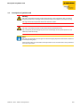


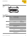

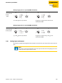

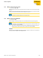


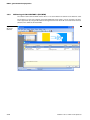
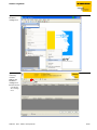
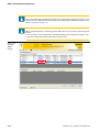
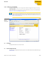


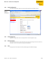

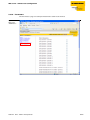


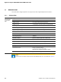


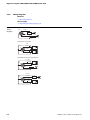


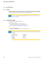
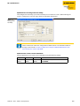

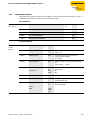
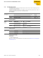

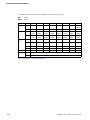

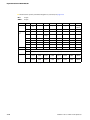
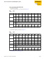
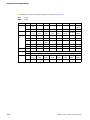
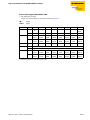
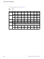

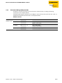

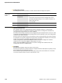

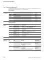
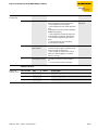
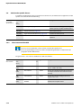
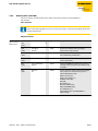
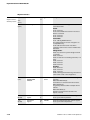

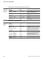


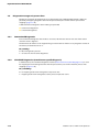
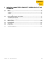
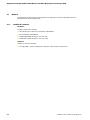
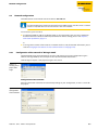
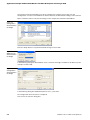
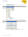

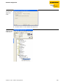

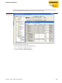
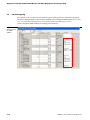
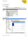

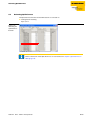


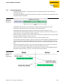


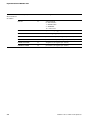
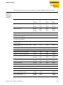
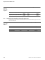
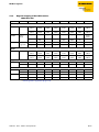


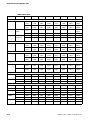
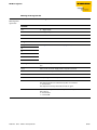
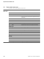

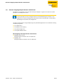


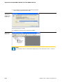


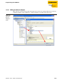
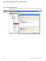


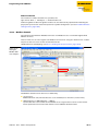
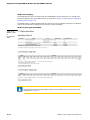
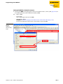

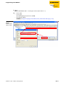
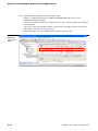

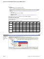


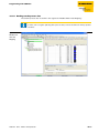
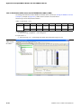


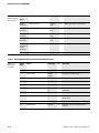

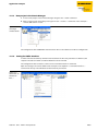


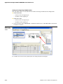
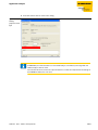
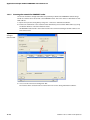

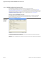
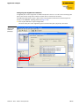

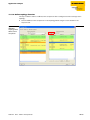
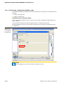
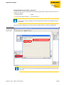


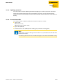
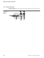


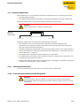


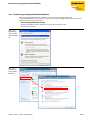

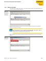


![[U4.53.31] Opérateur DYNA_ISS_VARI](http://vs1.manualzilla.com/store/data/006358565_1-9a1980e8e37a644a93155bf2f9c1ccbc-150x150.png)