1
BL20 –
USER MANUAL
MULTIPROTOCOL
Gateway
for ETHERNET
BL20-E-GW-EN
Sense it! Connect it! Bus it! Solve it!
All brand and product names are trademarks or registered trade marks of the owner
concerned.
Edition 07/2013
© Hans Turck GmbH, Muelheim an der Ruhr
All rights reserved, including those of the translation.
No part of this manual may be reproduced in any form (printed, photocopy, microfilm or any
other process) or processed, duplicated or distributed by means of electronic systems
without written permission of Hans Turck GmbH & Co. KG, Muelheim an der Ruhr.
Subject to alterations without notice
Table of Contents
1
About this manual
1.1
Documentation concept .................................................................................................................................1-2
1.1.1
Additional documentation .................................................................................................................................................................1-2
1.2
Description of symbols used ..........................................................................................................................1-3
1.3
General ............................................................................................................................................................1-4
1.3.1
1.3.2
Prescribed use .........................................................................................................................................................................................1-4
Notes concerning planning/ installation of this product ........................................................................................................1-4
1.4
List of revisions ................................................................................................................................................1-5
2
BL20-philosophy
2.1
The basic concept ............................................................................................................................................2-2
2.1.1
2.1.2
2.1.3
Flexibility ...................................................................................................................................................................................................2-2
Compactness ...........................................................................................................................................................................................2-2
Easy to handle .........................................................................................................................................................................................2-2
2.2
BL20 components ............................................................................................................................................2-3
2.2.1
2.2.2
2.2.3
2.2.4
2.2.5
2.2.6
2.2.7
2.2.8
2.2.9
2.2.10
Gateways ...................................................................................................................................................................................................2-3
Power distribution modules...............................................................................................................................................................2-4
Electronics modules (standard product line) ...............................................................................................................................2-5
ECO electronics modules.....................................................................................................................................................................2-6
Base modules...........................................................................................................................................................................................2-7
End plate....................................................................................................................................................................................................2-8
End bracket...............................................................................................................................................................................................2-8
Jumpers......................................................................................................................................................................................................2-9
Marking material.....................................................................................................................................................................................2-9
Shield connection gateway ............................................................................................................................................................. 2-10
3
Properties: gateway and I/O-modules
3.1
Function of the gateway .................................................................................................................................3-3
3.1.1
Version overview ....................................................................................................................................................................................3-3
3.2
Supported I/O-modules ..................................................................................................................................3-4
3.3
Technical data..................................................................................................................................................3-6
3.3.1
3.3.2
3.3.3
3.3.4
3.3.5
3.3.6
Top view BL20-E-GW-EN (< VN 03-00) ...........................................................................................................................................3-6
Top view BL20-E-GW-EN (≥ VN 03-00) ..........................................................................................................................................3-7
Block diagram..........................................................................................................................................................................................3-8
General technical data of a station .................................................................................................................................................3-9
Technical data for the push-in tension clamp terminals ..................................................................................................... 3-11
LED-displays .......................................................................................................................................................................................... 3-12
3.4
Connection options at the gateway............................................................................................................ 3-14
3.4.1
3.4.2
3.4.3
Power supply ........................................................................................................................................................................................ 3-14
Field bus connection via Ethernet-switch .................................................................................................................................. 3-14
Service interface .................................................................................................................................................................................. 3-14
3.5
Address assignment ..................................................................................................................................... 3-15
3.5.1
3.5.2
Default setting of the gateway....................................................................................................................................................... 3-15
Function of DIP-switches.................................................................................................................................................................. 3-16
D301173 0713 - BL20- Ethernet multiprotocol gateway
i
3.5.3
3.5.4
3.5.5
3.5.6
3.5.7
3.5.8
3.5.9
3.5.10
3.5.11
Resetting the IP-address, switch position "RESTORE".............................................................................................................3-17
Address setting via DIP-switches (20 to 27).................................................................................................................................3-18
Address setting via the mode DHCP.............................................................................................................................................3-19
Address setting via the mode BootP ............................................................................................................................................3-20
Address setting via the mode PGM...............................................................................................................................................3-21
Address setting via the mode PGM-DHCP (universal mode)...............................................................................................3-22
F_Reset (Reset to factory setting) ..................................................................................................................................................3-22
Addressing via I/O-ASSISTANT 3 (FDT/DTM) .............................................................................................................................3-23
Addressing via Web server (Version ≥ VN 03-00) ....................................................................................................................3-26
3.6
Synchronization of the station configuration ............................................................................................ 3-27
3.6.1
DIP-switch CFG .....................................................................................................................................................................................3-27
3.7
Web server - remote access/configuration (Version ≥ VN 03-00)............................................................. 3-28
3.7.1
3.7.2
3.7.3
3.7.4
3.7.5
3.7.6
3.7.7
3.7.8
3.7.9
IP address................................................................................................................................................................................................3-28
Access rights ..........................................................................................................................................................................................3-28
Login / password..................................................................................................................................................................................3-29
Network Configuration......................................................................................................................................................................3-29
Gateway Configuration .....................................................................................................................................................................3-30
Station Diagnostics .............................................................................................................................................................................3-30
Ethernet Statistics ................................................................................................................................................................................3-30
Links..........................................................................................................................................................................................................3-30
Change Admin Password..................................................................................................................................................................3-31
3.8
Status and Control Word of the BL20-stations........................................................................................... 3-32
3.8.1
3.8.2
Status Word............................................................................................................................................................................................3-32
Control Word.........................................................................................................................................................................................3-32
3.9
Parameters of the I/O-modules................................................................................................................... 3-33
3.9.1
3.9.2
3.9.3
3.9.4
Digital input modules ........................................................................................................................................................................3-33
Analog input modules .......................................................................................................................................................................3-33
Analog output modules ....................................................................................................................................................................3-42
Technology modules..........................................................................................................................................................................3-47
3.10
Diagnostic messages of the modules.......................................................................................................... 3-56
3.10.1
3.10.2
3.10.3
3.10.4
3.10.5
3.10.6
Power distribution modules ............................................................................................................................................................3-56
Digital input modules ........................................................................................................................................................................3-57
Analog input modules .......................................................................................................................................................................3-57
Digital output modules .....................................................................................................................................................................3-60
Analog output modules ....................................................................................................................................................................3-62
Technology modules..........................................................................................................................................................................3-63
4
Implementation of EtherNet/IP™
4.1
Diagnostic messages via the process data ................................................................................................... 4-2
4.1.1
4.1.2
Summarized Diagnostics .................................................................................................................................................................... 4-2
Scheduled Diagnostics ........................................................................................................................................................................ 4-2
4.2
Classes and Instances of the EtherNet/IP™-stations .................................................................................... 4-3
4.2.1
4.2.2
4.2.3
4.2.4
4.2.5
4.2.6
EtherNet/IP™ Standard Classes ......................................................................................................................................................... 4-3
Identity Object (0x01)........................................................................................................................................................................... 4-4
Assembly Object (0x04)....................................................................................................................................................................... 4-6
Connection Manager Object (0x06)................................................................................................................................................ 4-9
TCP/IP Interface Object (0xF5) ........................................................................................................................................................4-10
Ethernet Link Object (0xF6)..............................................................................................................................................................4-14
ii
D301173 0713 - BL20- Ethernet multiprotocol gateway
4.3
VSC-Vendor Specific Classes........................................................................................................................ 4-16
4.3.1
4.3.2
4.3.3
4.3.4
Class Instance of the VSCs................................................................................................................................................................ 4-16
Gateway Class (VSC 100, 64h) ......................................................................................................................................................... 4-17
Process Data Class (VSC102, 66h) .................................................................................................................................................. 4-20
Miscellaneous Parameters Class (VSC 126) ................................................................................................................................ 4-22
5
Application example: BL20-E-GW-EN with EtherNet/IP™ (Allen Bradley)
5.1
General .............................................................................................................................................................5-2
5.1.1
Used hard-/ software.............................................................................................................................................................................5-2
5.2
Network configuration....................................................................................................................................5-3
5.2.1
5.2.2
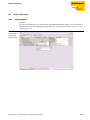
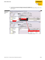
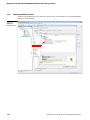
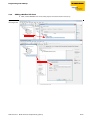
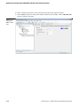
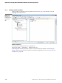
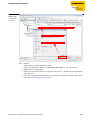
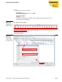
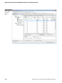
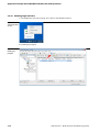
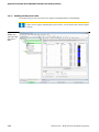
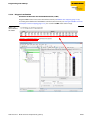
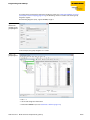
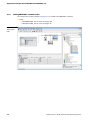
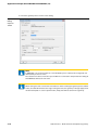
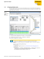
Configuration of the network in "RS Logix 5000" .......................................................................................................................5-3
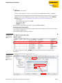
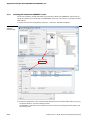
Downloading the I/O configuration................................................................................................................................................5-7
5.3
I/O data mapping.............................................................................................................................................5-9
5.4
Process data access ...................................................................................................................................... 5-11
5.4.1
5.4.2
Setting outputs .................................................................................................................................................................................... 5-11
Example program................................................................................................................................................................................ 5-12
6
Implementation of Modbus TCP
6.1
Common Modbus description ........................................................................................................................6-2
6.1.1
6.1.2
Protocol description..............................................................................................................................................................................6-3
Data model ...............................................................................................................................................................................................6-4
6.2
Implemented Modbus functions....................................................................................................................6-6
6.3
Modbus registers.............................................................................................................................................6-7
6.3.1
6.3.2
6.3.3
6.3.4
6.3.5
6.3.6
6.3.7
6.3.8
6.3.9
Structure of the packed in-/ output process data ................................................................................................................... 6-12
Register 0x100C: Gateway status................................................................................................................................................... 6-16
Register 0x1130h: Modbus-Connection-Mode ........................................................................................................................ 6-17
Register 0x1131: Modbus-Connection-Timeout...................................................................................................................... 6-17
Register 0x113C and 0x113D: Restore Modbus-connection parameters ....................................................................... 6-17
Register 0x113E and 0x113F: „Save Modbus-Connection-Parameters“.......................................................................... 6-18
Register 0x1140: Disable protocol................................................................................................................................................. 6-18
Register 0x1141: Active protocol................................................................................................................................................... 6-18
Register 0x2000 bis 0x207F: The Service-Object ..................................................................................................................... 6-19
6.4
Bit areas: mapping of input-discrete- and coil-areas ................................................................................ 6-22
6.5
Error behavior of outputs (watchdog) ........................................................................................................ 6-23
7
Application example: BL20-E-GW-EN for Modbus TCP (CoDeSys Win V3)
7.1
Used hard-/ software.......................................................................................................................................7-2
7.1.1
7.1.2
Hardware ...................................................................................................................................................................................................7-2
Software.....................................................................................................................................................................................................7-2
7.2
Network configuration....................................................................................................................................7-3
7.3
Programming with CoDeSys...........................................................................................................................7-4
7.3.1
7.3.2
7.3.3
7.3.4
Predefined feature sets ........................................................................................................................................................................7-4
Creating a new project .........................................................................................................................................................................7-5
Defining the communication settings............................................................................................................................................7-7
Adding the Ethernet Adapter ............................................................................................................................................................7-9
D301173 0713 - BL20- Ethernet multiprotocol gateway
iii
7.3.5
7.3.6
7.3.7
7.3.8
7.3.9
7.3.10
7.3.11
7.3.12
Adding the Modbus master .............................................................................................................................................................7-10
Adding a Modbus TCP slave ............................................................................................................................................................7-11
Programming (example program) ................................................................................................................................................7-13
CoDeSys: Global variables ................................................................................................................................................................7-14
Modbus channels.................................................................................................................................................................................7-15
Building, login and start ....................................................................................................................................................................7-26
Reading out the process data .........................................................................................................................................................7-28
Diagnosis evaluation ..........................................................................................................................................................................7-29
8
Implementation of PROFINET®
8.1
Address assignment ....................................................................................................................................... 8-2
8.2
GSDML-file....................................................................................................................................................... 8-3
8.3
Default-values ................................................................................................................................................. 8-3
8.4
Diagnosis in PROFINET® ................................................................................................................................. 8-4
8.4.1
8.4.2
Gateway Error codes ............................................................................................................................................................................ 8-4
Channel -specific error codes of the I/O-modules .................................................................................................................... 8-5
8.5
Parameterization .......................................................................................................................................... 8-10
8.5.1
8.5.2
8.5.3
Gateway parameters...........................................................................................................................................................................8-10
I/O-module-parameters ....................................................................................................................................................................8-13
Parameter "module parameterization"........................................................................................................................................8-13
8.6
Description of user data for acyclic services............................................................................................... 8-14
8.6.1
8.6.2
Description of the acyclic gateway user data............................................................................................................................8-14
Description of the acyclic module user data .............................................................................................................................8-15
9
Application example: BL20-E-GW-EN with PROFINET® (S7)
9.1
Application example ...................................................................................................................................... 9-2
9.1.1
9.1.2
9.1.3
9.1.4
9.1.5
9.1.6
9.1.7
9.1.8
9.1.9
9.1.10
General ...................................................................................................................................................................................................... 9-2
Example network ................................................................................................................................................................................... 9-2
New project in the Simatic Manager .............................................................................................................................................. 9-3
Setting the PG/PC-interface............................................................................................................................................................... 9-3
Installation of the GSDML-files.......................................................................................................................................................... 9-4
Adding PROFINET®-network nodes................................................................................................................................................. 9-8
Configuring the BL20-station ..........................................................................................................................................................9-11
Scanning the network for PROFINET® nodes.............................................................................................................................9-12
PROFINET® neighborhood detection via LLDP .........................................................................................................................9-14
Online topology detection...............................................................................................................................................................9-17
9.2
Diagnostics with Step 7 ................................................................................................................................ 9-18
9.2.1
9.2.2
Diagnostic messages in the hardware configuration.............................................................................................................9-18
Diagnostic telegram with error code ...........................................................................................................................................9-19
10
Guidelines for station planning
10.1
Module arrangement.................................................................................................................................... 10-2
10.1.1 Random module arrangement .......................................................................................................................................................10-2
10.1.2 Complete planning .............................................................................................................................................................................10-2
10.1.3 Maximum system extension............................................................................................................................................................10-3
10.2
Power supply................................................................................................................................................. 10-6
10.2.1 Power supply to the gateway..........................................................................................................................................................10-6
iv
D301173 0713 - BL20- Ethernet multiprotocol gateway
10.2.2
10.2.3
10.2.4
10.2.5
Module bus refreshing (BL20-BR-24VDC-D) .............................................................................................................................. 10-6
Creating potential groups................................................................................................................................................................ 10-7
C-rail (cross connection) ................................................................................................................................................................... 10-7
Direct wiring of relay modules ....................................................................................................................................................... 10-9
10.3
Protecting the service interface on the gateway ..................................................................................... 10-10
10.4
Plugging and pulling electronics modules............................................................................................... 10-10
10.5
Extending an existing station.................................................................................................................... 10-10
10.6
Firmware download ................................................................................................................................... 10-11
11
Guidelines for Electrical Installation
11.1
General notes................................................................................................................................................ 11-2
11.1.1
11.1.2
11.1.3
11.1.4
General .................................................................................................................................................................................................... 11-2
Cable routing ........................................................................................................................................................................................ 11-2
Lightning protection.......................................................................................................................................................................... 11-3
Transmission media............................................................................................................................................................................ 11-3
11.2
Potential relationships................................................................................................................................. 11-4
11.2.1 General .................................................................................................................................................................................................... 11-4
11.3
Electromagnetic compatibility(EMC ........................................................................................................... 11-5
11.3.1
11.3.2
11.3.3
11.3.4
11.3.5
Ensuring electromagnetic compatibility .................................................................................................................................... 11-5
Grounding of inactive metal components................................................................................................................................. 11-5
PE connection....................................................................................................................................................................................... 11-5
Earth-free operation ........................................................................................................................................................................... 11-5
Mounting rails....................................................................................................................................................................................... 11-6
11.4
Shielding of cables ....................................................................................................................................... 11-7
11.5
Potential compensation............................................................................................................................... 11-8
11.5.1 Switching inductive loads ................................................................................................................................................................ 11-8
11.5.2 Protection against Electrostatic Discharge (ESD) .................................................................................................................... 11-8
12
BL20-Approvals for Zone 2/ Division 2
13
Appendix
13.1
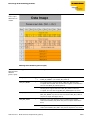
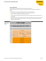
Data image of the technology modules ..................................................................................................... 13-2
13.1.1
13.1.2
13.1.3
13.1.4
13.1.5
1RS232/ 1RS485-module .................................................................................................................................................................. 13-2
SSI module ............................................................................................................................................................................................. 13-6
SWIRE-module....................................................................................................................................................................................13-13
Encoder/PWM-moduleBL20-E-2CNT-2PWM ...........................................................................................................................13-15
RFID-moule BL20-2RFID-S/ -A.......................................................................................................................................................13-15
13.2
Changing the IP address of a PC/ network interface card ....................................................................... 13-16
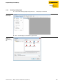
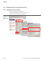
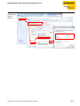
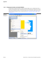
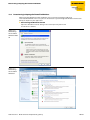
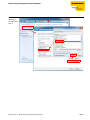
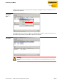
13.2.1 Changing the IP address in Windows ........................................................................................................................................13-16
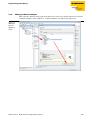
13.2.2 Changing the IP address via I/O-ASSISTANT V3 .....................................................................................................................13-18
13.3
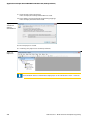
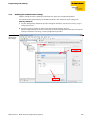
Deactivating/ adapting the firewall in Windows ..................................................................................... 13-19
13.4
Addressing via DHCP.................................................................................................................................. 13-22
13.5
Ident codes the BL20-modules ................................................................................................................. 13-24
14
Glossary
D301173 0713 - BL20- Ethernet multiprotocol gateway
v
15
vi
Index
D301173 0713 - BL20- Ethernet multiprotocol gateway
1
About this manual
1.1
Documentation concept ............................................................................................................................1-2
1.1.1
Additional documentation........................................................................................................................................................... 1-2
1.2
Description of symbols used .....................................................................................................................1-3
1.3
General .......................................................................................................................................................1-4
1.3.1
1.3.2
Prescribed use................................................................................................................................................................................... 1-4
Notes concerning planning/ installation of this product.................................................................................................. 1-4
1.4
List of revisions ...........................................................................................................................................1-5
D301173 0713 - BL20- Ethernet multiprotocol gateway
1-1
About this manual
1.1
Documentation concept
This manual contains all information about the gateways BL20-E-GW-EN of the product line BL20 .
Version < VN 03-00: gateway for Modbus TCP
Version ≥ VN 03-00: multiprotocol-gateway for Modbus TCP, EtherNet/IP™, PROFINET®
In addition to a short BL20-system description and the protocol-independent properties of the gateway
and if necessary of the I/O-modules (technical properties, diagnostics, parameters, etc.), the following
chapters contain two protocol-dependent chapters respectively.
The protocol-dependent chapters contain on the one hand the protocol-specific gateway-properties
and on the other hand an application example for the respective Ethernet-protocol, describing the
device's connection to automation devices.
EtherNet/IP™
– chapter 4, Implementation of EtherNet/IP™
– chapter 5, Application example: BL20-E-GW-EN with EtherNet/IP™ (Allen Bradley)
Modbus TCP
– chapter 6, Implementation of Modbus TCP
– chapter 7, Application example: BL20-E-GW-EN for Modbus TCP (CoDeSys Win V3)
PROFINET®
– chapter 8, Implementation of PROFINET®
– chapter 9, Application example: BL20-E-GW-EN with PROFINET® (S7)
Additionally, the manual contain protocol-independent guideline for station configuration, the
electrical installation, etc..
1.1.1
Additional documentation
BL20 I/O-modules (TURCK-documentation no.: German D300716; English D300717).
The bus-independent I/O-modules of the BL20-system as well as all bus independent information
as mounting, labeling etc. are described in a separate manual.
In addition to that, the manual contains a short description of the I/O-ASSISTANT, the project
planning and configuration software tool for TURCK I/O-systems BL20-E-2CNT-2PWM, (TURCK-documentation no.: German D301223; English D301224)
1-2
D301173 0713 - BL20- Ethernet multiprotocol gateway
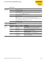
Description of symbols used
1.2
Description of symbols used
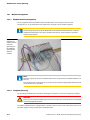
Warning
This sign can be found next to all notes that indicate a source of hazards. This can refer to
danger to personnel or damage to the system (hardware and software) and to the facility.
This sign means for the operator: work with extreme caution.
Attention
This sign can be found next to all notes that indicate a potential hazard.
This can refer to possible danger to personnel and damages to the system (hardware and
software) and to the facility.
Note
This sign can be found next to all general notes that supply important information about one
or more operating steps.
These specific notes are intended to make operation easier and avoid unnecessary work due
to incorrect operation.
D301173 0713 - BL20- Ethernet multiprotocol gateway
1-3
About this manual
1.3
General
Attention
Please read this section carefully. Safety aspects cannot be left to chance when dealing with
electrical equipment.
This manual includes all information necessary for the prescribed use of the BL20-E-GW-EN. It has been
specially conceived for personnel with the necessary qualifications.
1.3.1
Prescribed use
Appropriate transport, storage, deployment and mounting as well as careful operating and thorough
maintenance guarantee the trouble-free and safe operation of these devices.
Warning
The devices described in this manual must be used only in applications prescribed in this
manual or in the respective technical descriptions, and only with certified components and
devices from third party manufacturers.
1.3.2
Notes concerning planning/ installation of this product
Warning
All respective safety measures and accident protection guidelines must be considered
carefully and without exception.
1-4
D301173 0713 - BL20- Ethernet multiprotocol gateway
List of revisions
1.4
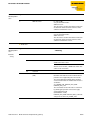
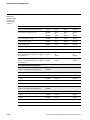
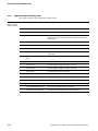
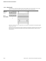
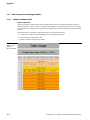
List of revisions
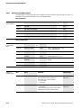
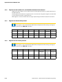
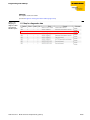
In comparison to the previous manual edition, the following changes/ revisions have been made.
Tabelle 1-1:
List of revisions
Chapter
Topic
new
Chap. 3
Version overview (page 3-3)
X
Top view BL20-E-GW-EN (< VN 03-00), page 3-6
X
Top view BL20-E-GW-EN (≥ VN 03-00), page 3-7
X
Chap. 7
changed
LED-displays (page 3-12)
X
Function of DIP-switches (page 3-16)
X
Addressing via IP Address Tool (page 3-27)
X
Diagnosis evaluation (page 7-29)
X
Note
The publication of this manual renders all previous editions invalid.
D301173 0713 - BL20- Ethernet multiprotocol gateway
1-5
About this manual
1-6
D301173 0713 - BL20- Ethernet multiprotocol gateway
2
BL20-philosophy
2.1
The basic concept ....................................................................................................................................... 2-2
2.1.1
2.1.2
2.1.3
Flexibility .............................................................................................................................................................................................2-2
Compactness .....................................................................................................................................................................................2-2
Easy to handle ...................................................................................................................................................................................2-2
2.2
BL20 components....................................................................................................................................... 2-3
2.2.1
Gateways .............................................................................................................................................................................................2-3
– ECO-gateways ...............................................................................................................................................................................2-3
– Gateways with integrated power supply ............................................................................................................................2-4
– Gateways without integrated power supply .....................................................................................................................2-4
Power distribution modules.........................................................................................................................................................2-4
Electronics modules (standard product line).........................................................................................................................2-5
ECO electronics modules...............................................................................................................................................................2-6
Base modules.....................................................................................................................................................................................2-7
End plate..............................................................................................................................................................................................2-8
End bracket.........................................................................................................................................................................................2-8
Jumpers ...............................................................................................................................................................................................2-9
Marking material ..............................................................................................................................................................................2-9
Shield connection gateway ....................................................................................................................................................... 2-10
2.2.2
2.2.3
2.2.4
2.2.5
2.2.6
2.2.7
2.2.8
2.2.9
2.2.10
D301173 0713 - BL20- Ethernet multiprotocol gateway
2-1
BL20-philosophy
2.1
The basic concept
BL20 is a modular I/O system for use in industrial automation. It connects the sensors and actuators in
the field with the higher-level master.
BL20 offers modules for practically all applications:
Digital input and output modules
Analog input and output modules
Technology modules (counters, RS232 interface...)
A complete BL20 station counts as one station on the bus and therefore occupies one fieldbus address
in any given fieldbus structure.
A BL20 station consists of a gateway, power distribution modules and I/O modules.
The connection to the relevant fieldbus is made via the bus-specific gateway, which is responsible for
the communication between the BL20 station and the other fieldbus stations.
The communication within the BL20 station between the gateway and the individual BL20 modules is
regulated via an internal module bus.
Note
The gateway is the only fieldbus-dependent module on a BL20 station. All other BL20
modules are not dependent on the fieldbus used.
2.1.1
Flexibility
All BL20 stations can be planned to accommodate the exact number of channels to suit your needs,
because the modules are available with different numbers of channels in block and slice design.
A BL20 station can contain modules in any combination, which means it is possible to adapt the system
to practically all applications in automated industry.
2.1.2
Compactness
The slim design of the BL20 modules (standard gateway 50.4 mm / 1.98 inch, ECO gateway 34 mm/ 1.34
inch, standard slice 12.6 mm / 0.49 inch, ECO slice 13 mm / 0.51 inch and block 100.8 mm / 3.97 inch)
and their low overall height favor the installation of this system in confined spaces.
2.1.3
Easy to handle
All BL20 modules of the standard line, with the exception of the gateway, consist of a base module and
an electronics module.
The gateway and the base modules are snapped onto a mounting rail. The electronics modules are
plugged onto the appropriate base modules.
The base modules of the standard line are designed as terminal blocks. The wiring is secured by tension
clamp or screw connection.
The electronics modules can be plugged or pulled when the station is being commissioned or for
maintenance purposes, without having to disconnect the field wiring from the base modules.
The ECO electronics modules combine base module and electronics module in one housing. All BL20ECO modules can be used with the standard products with tension clamp connection technology.
2-2
D301173 0713 - BL20- Ethernet multiprotocol gateway
BL20 components
2.2
2.2.1
BL20 components
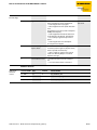
Gateways
The gateway connects the fieldbus to the I/O modules. It is responsible for handling the entire process
data and generates diagnostic information for the higher-level master and the software tool I/OASSISTANT.
ECO-gateways
The BL20-ECO gateways enlarge the product portfolio of BL20. They offer an excellent cost/
performance ratio.
Further advantages of the gateways in the ECO-housing:
At the moment available for PROFIBUS-DP, DeviceNet™, CANopen, Modbus TCP, EtherNet/IP™,
EtherCAT® and PROFINET®
Low required space: width 34 mm/ 1.34 inch minimal space requirements
Can be combined with all existing standard modules (with tension clamp connection technology)
and ECO modules
Simple wiring with "Push-in" tension clamp terminals, via DeviceNet™-Open Style Connector or via
Ethernet RJ45-connectors
Automatic bit rate detection for PROFIBUS-DP and DeviceNet™
Setting of fieldbus address and bus terminating resistor (PROFIBUS-DP, DeviceNet™, CANopen) via
DIP-switches
Service interface for commissioning with I/O-ASSISTANT 3 (FDT/DTM), without PLC)
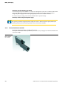
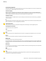
Figure 2-1:
Gateway
BL20-E-GW-EN
D301173 0713 - BL20- Ethernet multiprotocol gateway
2-3
BL20-philosophy
Gateways with integrated power supply
All standard gateways BL20-GWBR-××× as well as the BL20-gateways for DPV1 and Ethernet (BL20-GWDPV1, BL20-GW-EN, BL20-GW-EN-IP, BL20-GW-EN-PN, BL20-PG-EN and BL20-PG-EN-IP) offer an
integrated power supply unit for feeding the gateway and the connected I/O modules.
It is not necessary to supply each individual module with a separate voltage.
Gateways without integrated power supply
Note
The gateways without integrated power supply unit need an additional power supply module (bus
refreshing module) which feeds the gateway an the connected I/O modules.
2.2.2
Power distribution modules
The power supply for gateways and I/O modules is fed
to the power distribution modules; therefore, it is not necessary to supply each individual module with
a separate voltage.
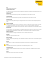
Figure 2-2:
Power distribution module
2-4
D301173 0713 - BL20- Ethernet multiprotocol gateway
BL20 components
2.2.3
Electronics modules (standard product line)
The standard electronics modules contain the I/O-functions of the BL20 modules (power distribution
modules, digital and analog input/output modules, and technology modules).
They are plugged onto the base modules and are not directly connected to the wiring
and can be plugged or pulled when the station is being commissioned or for maintenance purposes,
without having to disconnect the field wiring from the base modules.
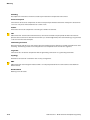
Figure 2-3:
Electronics
module in slice
design (left) and
in Block design
(right)
D301173 0713 - BL20- Ethernet multiprotocol gateway
2-5
BL20-philosophy
2.2.4
ECO electronics modules
New ECONOMY modules with a high signal density and exceptionally low channel price expand the
BL20 I/O bus terminal system.
Depending on type, up to 16 digital inputs and outputs can be connected on only 13 mm. This high
connection density considerably reduces the mounting width required for typical applications.
All advantages at a glance:
Space saving thanks to 16 channels on 13 mm/ 0.51 inch width
Cost saving thanks to electronics with integrated connection level
High signal density
Tool-less connection via "push-in" spring-type terminal technology for simple and fast mounting
Flexibility in combining them with standard I/O-modules in tension clamp technology, the
standard- and the ECO-gateways.
Simple assembly reduces error sources
Figure 2-4:
ECO I/O-module
2-6
D301173 0713 - BL20- Ethernet multiprotocol gateway
BL20 components
2.2.5
Base modules
The field wiring is connected to the base modules. These are constructed as terminals in block and slice
designs and are available in the following variations with either tension clamp or screw connections: 2/3-wire (2-channel), 4-wire (2-channel) and 4 x 2-/3-wire (4-channel).
Figure 2-5:
Base module
with tension
clamp connection
Figure 2-6:
Base module
with screw
connection
Figure 2-7:
Base module in
block design
D301173 0713 - BL20- Ethernet multiprotocol gateway
2-7
BL20-philosophy
2.2.6
End plate
An end plate on the right-hand side physically completes the BL20 station. An end bracket mounted
into the end plate ensures that the BL20 station remains secure on the mounting rail even when
subjected to vibration.
Figure 2-8:
End plate
2.2.7
End bracket
A second end bracket to the left of the gateway is necessary, as well as the one mounted into the end
plate to secure the station.
Figure 2-9:
End bracket
Note
The end plate and two end brackets are delivered with the gateway.
2-8
D301173 0713 - BL20- Ethernet multiprotocol gateway
BL20 components
2.2.8
Jumpers
Jumpers (QVRs) are used to bridge a connection level of a 4-wire base module. They can be used to
connect potentials in relay modules (bridging the relay roots); thus considerably reducing the amount
of wiring.
Figure 2-10:
Jumpers
2.2.9
Marking material
Labels: for labeling BL20 electronics modules.
Markers: for colored identification of connection levels of BL20 base modules.
Dekafix connector markers: for numbering the mounting slots on BL20 base modules.
Figure 2-11:
Marking material
D301173 0713 - BL20- Ethernet multiprotocol gateway
2-9
BL20-philosophy
2.2.10
Shield connection gateway
If the gateway is wired directly to the fieldbus, it is possible to shield the connection using a special
gateway-shielding connection attachment (BS3511/KLBUE4-31.5).
Figure 2-12:
Shield connection (gateway)
2-10
D301173 0713 - BL20- Ethernet multiprotocol gateway
3
Properties: gateway and I/O-modules
3.1
Function of the gateway............................................................................................................................... 3
3.1.1
Version overview ..................................................................................................................................................................................3
3.2
Supported I/O-modules ................................................................................................................................ 4
3.3
Technical data................................................................................................................................................ 6
3.3.1
3.3.2
3.3.3
3.3.4
3.3.5
3.3.6
Top view BL20-E-GW-EN (< VN 03-00) .........................................................................................................................................6
Top view BL20-E-GW-EN (≥ VN 03-00) ........................................................................................................................................7
Block diagram........................................................................................................................................................................................8
General technical data of a station ...............................................................................................................................................9
– Approvals and tests...................................................................................................................................................................... 11
Technical data for the push-in tension clamp terminals ................................................................................................... 11
LED-displays ........................................................................................................................................................................................ 12
3.4
Connection options at the gateway........................................................................................................... 14
3.4.1
3.4.2
3.4.3
Power supply ...................................................................................................................................................................................... 14
Field bus connection via Ethernet-switch................................................................................................................................ 14
Service interface ................................................................................................................................................................................ 14
3.5
Address assignment.................................................................................................................................... 15
3.5.9
3.5.10
3.5.11
3.5.12
– LED behavior................................................................................................................................................................................... 15
Default setting of the gateway..................................................................................................................................................... 15
Function of DIP-switches................................................................................................................................................................ 16
Resetting the IP-address, switch position "RESTORE" .......................................................................................................... 17
Address setting via DIP-switches (20 to 27) .............................................................................................................................. 18
Address setting via the mode DHCP .......................................................................................................................................... 19
Address setting via the mode BootP.......................................................................................................................................... 20
Address setting via the mode PGM ............................................................................................................................................ 21
Address setting via the mode PGM-DHCP (universal mode) ............................................................................................ 22
– PROFINET® ....................................................................................................................................................................................... 22
F_Reset (Reset to factory setting)................................................................................................................................................ 22
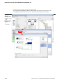
Addressing via I/O-ASSISTANT 3 (FDT/DTM)........................................................................................................................... 23
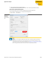
Addressing via Web server (Version ≥ VN 03-00).................................................................................................................. 26
Addressing via IP Address Tool .................................................................................................................................................... 27
3.6
Synchronization of the station configuration .......................................................................................... 28
3.6.1
DIP-switch CFG................................................................................................................................................................................... 28
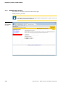
3.7
Web server - remote access/configuration (Version ≥ VN 03-00) ........................................................... 29
3.7.1
3.7.2
3.7.3
3.7.4
3.7.5
3.7.6
3.7.7
3.7.8
3.7.9
IP address ............................................................................................................................................................................................. 29
Access rights ....................................................................................................................................................................................... 29
Login / password............................................................................................................................................................................... 30
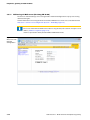
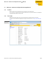
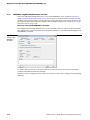
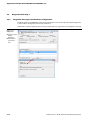
Network Configuration ................................................................................................................................................................... 30
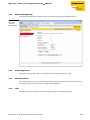
Gateway Configuration................................................................................................................................................................... 31
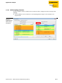
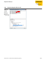
Station Diagnostics........................................................................................................................................................................... 31
Ethernet Statistics ............................................................................................................................................................................. 31
Links ....................................................................................................................................................................................................... 31
Change Admin Password ............................................................................................................................................................... 32
3.5.1
3.5.2
3.5.3
3.5.4
3.5.5
3.5.6
3.5.7
3.5.8
D301173 0713 - BL20- Ethernet multiprotocol gateway
3-1
Properties: gateway and I/O-modules
3.8
Status and Control Word of the BL20-stations..........................................................................................33
3.8.1
3.8.2
Status Word .........................................................................................................................................................................................33
– Meaning of the status bits..........................................................................................................................................................33
Control Word.......................................................................................................................................................................................33
3.9
Parameters of the I/O-modules .................................................................................................................34
3.9.1
3.9.2
3.9.3
3.9.4
Digital input modules ......................................................................................................................................................................34
Analog input modules .....................................................................................................................................................................34
Analog output modules ..................................................................................................................................................................43
Technology modules........................................................................................................................................................................48
3.10
Diagnostic messages of the modules.........................................................................................................57
3.10.1
3.10.2
3.10.3
3.10.4
3.10.5
3.10.6
Power distribution modules ..........................................................................................................................................................57
Digital input modules ......................................................................................................................................................................58
Analog input modules .....................................................................................................................................................................58
Digital output modules ...................................................................................................................................................................61
Analog output modules ..................................................................................................................................................................63
Technology modules........................................................................................................................................................................64
3-2
D301173 0713 - BL20- Ethernet multiprotocol gateway
Function of the gateway
3.1
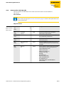
Function of the gateway
The BL20-E-GW-EN (> VN 03-00) is used as multiprotocol-interface between the BL20-system and the
Ethernet-protocols Modbus TCP, EtherNet/IP™ and PROFINET®.
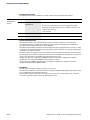
3.1.1
Version overview
Please observe, that the previous version of the gaetway did only support the Modbus TCP protocol.
Version < VN 03-00
BL20-gateway supports only the Ethernet protocol
– Modbus TCP
Version ≥ VN 03-00
BL20-gateway supports the Ethernet protocols
– Modbus TCP
– EtherNet/IP™
– PROFINET®
Note
The multiprotocol gateway replaces the Modbus TCP version and is fully compatible.
Only the LED-designation has changed. Please find detailed information under LED-displays
(page 3-12).
D301173 0713 - BL20- Ethernet multiprotocol gateway
3-3
Properties: gateway and I/O-modules
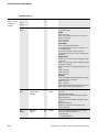
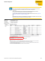
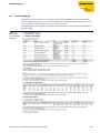
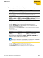
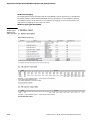
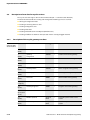
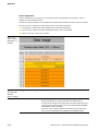
3.2
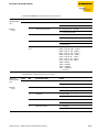
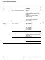
Supported I/O-modules
Table 3-1:
Module
List of supported
modules
EtherNet/IP™
Modbus TCP
PROFINET®
Digital input modules
BL20-2DI-24VDC-P
9
9
9
BL20-2DI-24VDC-N
9
9
9
BL20-2DI-120/230VAC
9
9
9
BL20-4DI-24VDC-P
9
9
9
BL20-4DI-24VDC-N
9
9
9
BL20-4DI-NAMUR
9
9
9
BL20-E-8DI-24VDC-P
9
9
9
BL20-16DI-24VDC-P
9
9
9
BL20-E-16DI-24VDC-P
9
9
9
BL20-32DI-24VDC-P
9
9
9
BL20-1AI-I(0/4…20MA)
9
9
9
BL20-2AI-I(0/4…20MA)
9
9
9
BL20-1AI-U(-10/0…+10VDC)
9
9
9
BL20-2AI-U(-10/0…+10VDC)
9
9
9
BL20-2AI-PT/NI-2/3
9
9
9
BL20-2AI-THERMO-PI
9
9
9
Analog input modules
9
BL20-2AI-H
BL20-4AI-U/I
9
9
9
BL20-E-4AI-TC
9
9
9
BL20-E-8AI-U/I-4AI-PT/NI
9
9
9
BL20-2DO-24VDC-0,5A-P
9
9
9
BL20-2DO-24VDC-0,5A-N
9
9
9
BL20-2DO-24VDC-2A-P
9
9
9
BL20-2DO-120/230VAC-0.5A
9
9
9
BL20-4DO-24VDC-0,5A-P
9
9
9
BL20-E-8DO-24VDC-0.5A-P
9
9
9
BL20-16DO-24VDC-0,5A-P
9
9
9
Digital output modules
3-4
D301173 0713 - BL20- Ethernet multiprotocol gateway
Supported I/O-modules
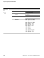
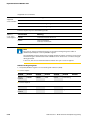
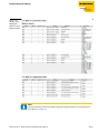
Table 3-1:
Module
List of supported
modules
EtherNet/IP™
Modbus TCP
PROFINET®
BL20-E-16DO-24VDC-0.5A-P
9
9
9
BL20-32DO-24VDC-0,5A-P
9
9
9
BL20-1AO-I(0/4…20MA)
9
9
9
BL20-2AO-I(0/4…20MA)
9
9
9
BL20-2AO-U(-10/0…+10VDC)
9
9
9
Analog output modules
9
BL20-2AO-H
9
9
9
BL20-2DO-R-NC
9
9
9
BL20-2DO-R-NO
9
9
9
BL20-2DO-R-CO
9
9
9
BL20-1RS232
9
9
9
BL20-1RS485/422
9
9
9
BL20-1SSI
9
9
9
BL20-E-1SWIRE
9
9
9
BL20-E-2CNT-2PWM
9
9
9
BL20-E-4AO-U/I
Relay modules
Technology modules
9
BL20-2RFID-A
9
9
9
BL20-BR-24VDC-D
9
9
9
BL20-BR-24 VDC-RED
9
9
9
BL20-PF-24VDC-D
9
9
9
BL20-PF-120/230VAC-D
9
9
9
BL20-2RFID-S
Power distribution modules
D301173 0713 - BL20- Ethernet multiprotocol gateway
3-5
Properties: gateway and I/O-modules
3.3
3.3.1
Technical data
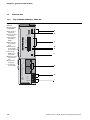
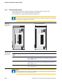
Top view BL20-E-GW-EN (< VN 03-00)
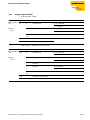
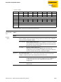
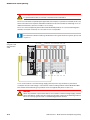
Figure 3-1:
Top view
BL20-E-GW-EN
(< VN 03-00)
IOs
ADDRESS
0
1
20
21
22
23
24
25
26
27
D
E
on
ETH2
F
G
ETH1
Slide top cover for configuration and service
Unlock end-bracket before dismounting
MS
UL
GNDL
H
USYS
GNDSYS
3-6
C
MODE
CFG
off
A
B
SERVICE
!
A LEDs for BL20
module bus
B service interface,
no function
C DIP-switch for
the fieldbusaddress
D DIP-switch for
the operation
mode
E DIP-switch for
the configuration acceptance
F LEDs for the
Modbus-communication
G EtherNet-switch
with EtherNetLEDs
H terminals for
field supply
I terminals for
system supply
GW
I
D301173 0713 - BL20- Ethernet multiprotocol gateway
Technical data
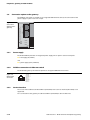
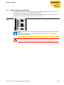
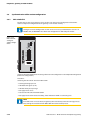
Top view BL20-E-GW-EN (≥ VN 03-00)
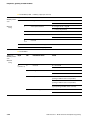
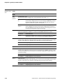
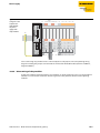
Figure 3-2:
Topview
BL20-E-GW-EN
(≥ VN 03-00)
GW
IOs
A
B
SERVICE
ADDRESS
0
1
20
21
22
23
24
25
26
27
C
D
E
MODE
CFG
off
on
ERR
ETH2
F
G
ETH1
Unlock end-bracket before dismounting
BUS
!
A LEDs for BL20
module bus
B service interface,
no function
C DIP-switch for
the fieldbusaddress
D DIP-switch for
the operation
mode
E DIP-switch for
the configuration acceptance
F LEDs for the
Ethernet-communication
G EtherNet-switch
with EtherNetLEDs
H terminals for
field supply
I terminals for
system supply
BL20-E-GW-EN
Slide top cover for configuration and service
3.3.2
UL
H
GNDL
USYS
GNDSYS
D301173 0713 - BL20- Ethernet multiprotocol gateway
I
3-7
Properties: gateway and I/O-modules
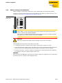
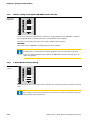
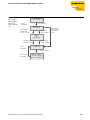
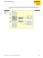
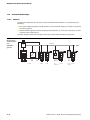
3.3.3
Block diagram
Figure 3-3:
Block diagram
BL20-E-GW-EN
Service USB
Module bus
CPU
Switch
5V
24 V
Eth1
Usys
Eth2
UL
Gateway
3-8
D301173 0713 - BL20- Ethernet multiprotocol gateway
Technical data
3.3.4
General technical data of a station
Attention
The auxiliary power supply must comply with the stipulations of SELV (Safety Extra Low
Voltage) according to IEC 364-4-41.
Table 3-2:
General technical data of a
station
Supply voltage/auxiliary voltage
Usys (nominal value)
provision for other modules
24 V DC
Isys (at max. system extension,
→ see chapter 10, from page 10-3)
approx. 600 mA
UL nominal value
24 V DC
ILmax,
maximum current from field supply
8A
permissible range
according to EN 61131-2 (18 to 30 V DC)
Residual ripple
according to EN 61 131-2
Voltage anomalies
according to EN 61 131-2
IMB (supply of module bus nodes)
400 mA
Connection technology
push-in tension clamps,
LSF from Weidmueller
Physical interfaces
Field bus
Ethernet
Transmission rate
10/100 Mbps
Passive fiber-optic-adapters can be
connected
current consumption max. 100 mA
Fieldbus connection technology
RJ45-female connector, RJ45-male connector
Fieldbus shielding connection
via Ethernet cable
Address setting
via DIP-switches (20 to 27)
service interface
Ethernet
Isolation voltages
UBL(Usys against service interface)
-
UETH (supply voltage against Ethernet)
500 V AC
UETH (supply voltage against Ethernet)
-
UETHETH (ETH1 against ETH2)
500 V AC
D301173 0713 - BL20- Ethernet multiprotocol gateway
3-9
Properties: gateway and I/O-modules
Ambient conditions
Ambient temperature
– tAmbient
0…+55 °C
– tStore
- 25…+85 °C
relative humidity according to
EN 61131-2/EN 50178
5 to 95 % (indoor), Level RH-2, no condensation
(storage at 45 °C, no function test)
Climatic tests
according to IEC 61131-2
Vibration resistance
10 to 57 Hz, constant amplitude 0.075 mm /
0.003 inch, 1g
yes
57 to 150 Hz
constant acceleration 1 g
yes
Mode of vibration
Frequency sweeps with a change in speed of 1
Octave/min
Period of oscillation
20 frequency sweeps per axis of coordinate
Shock resistant according to
IEC 68-2-27
18 shocks, sinusoidal half-wave 15 g peak value/11
ms, in each case in ± direction per space coordinate
Resistance to repetitive shock
IEC 68-2-29
1 000 shocks, half-sinus 25 g peak value/6 ms, in each
case in ± direction per space coordinate
Drop and topple
Height of fall (weight < 10 kg)
1.0 m
Height of fall (weight 10 to 40 kg)
0.5 m
Test runs
7
Device with packaging, electrically tested printed-circuit board.
A Using the device Electromagnetic compatibility (EMC) according to EN 50 082-2 (Industry)
in residential
areas can cause Static electricity according to EN 61 000-4-2
disturbances. In
– Discharge through air (direct)
8 kV
this case, additional measures
– Relay discharge (indirect)
4 kV
to suppress the
disturbance are
Electromagnetic HF fields according to EN 61 10 V/m
necessary.
000-4-3 and ENV 50 204
Conducted interferences induced by HF
fields according to EN 61 000-4-6
10 V
Fast transients (Burst) according to
EN 61 000-4-4
Emitted interference according to
EN 50 081-2 (industry)
3-10
according to EN 55 011 Class A A, group 1
D301173 0713 - BL20- Ethernet multiprotocol gateway
Technical data
Approvals and tests
Table 3-3:
Approvals and
tests for a BL20
station
Designation
Approvals
UL
CSA
in preparation
Tests (EN 61131-2)
Cold
DIN IEC 68-2-1, Temperature -25 °C / 185 °F, duration 96 h;
device not in use
Dry heat
DIN IEC 68-2-2, Temperature +85 °C / 185 °F, duration 96 h;
device not in use
Damp heat, cyclic
DIN IEC 68-2-30, temperature +55 °C / 131 °F, duration 2
cycles every 12 h; device in use
Pollution severity according to IEC 664 2
(EN 61 131-2)
Protection class according to IEC 529
3.3.5
IP20
Technical data for the push-in tension clamp terminals
Designation
Table 3-4:
Technical data
Push-in tension Protection class
clamp terminals Insulation stripping length
Max. wire range
IP20
8 mm + 1/ 0.32 inch + 0,039
0.14 to 1.5 mm2 / 0.0002 to 0.0023 inch2/ 26 to 16 AWG
Crimpable wire
"e” solid core H 07V-U
0.14 to 1.5 mm2 / 0.0002 to 0.0023 inch2/ 26 to 16 AWG
"f” flexible core H 07V-K
0.5 to 1.5 mm2 / 0.0008 to 0.0023 inch2/ 25 to 16 AWG
"f” with ferrules according to
DIN 46 228/1 (ferrules crimped gastight)
0.25 to 1.5 mm2 / 0.0004 to 0.0023 inch2/30 to 16 AWG
Danger
This device can cause radio disturbances in residential areas and in small industrial areas
(residential, business and trading). In this case, the operator can be required to take
appropriate measures to suppress the disturbance at his own cost.
D301173 0713 - BL20- Ethernet multiprotocol gateway
3-11
Properties: gateway and I/O-modules
3.3.6
LED-displays
Every BL20-E-GW-EN displays the following statuses via LEDs:
2 LEDs for the module bus communication (module bus-LEDs): GW and IOs
< VN 03-00:
1 LEDs for the field bus communication: MS
VN ≥ 03-00:
2 LEDs for the field bus communication: ERR and BUS
2 LEDs for the status of the Ethernet-connection at the Ethernet-ports ETH1/ ETH2:
Table 3-5:
LED-displays
LED
Status
Meaning
Remedy
GW
OFF
No power supply of the CPU.
Check the system power supply at the
gateway.
green
Firmware active, gateway ready
-
green
flashing,
1 Hz
Firmware not active
If LED “IOs“ red, firmware-download
necessary
green
flashing,
4 Hz
Firmware active, gateway
hardware error.
Replace the gateway.
red
CPU not ready, VCC too low →
possible causes:
– too many modules at the
gateway
– short-circuit in connected
module
– gateway hardware error.
– Check the system power supply at the
gateway and the cabling.
– Unmount excessively mounted
modules.
– Replace the gateway, if necessary.
red / green
flashing, 4 Hz
WINK-command active
OFF
No power supply of the CPU.
Check the system power supply at the
gateway.
green
The modules configured
correspond to the modules in
the station, communication
running.
-
green
flashing,
1 Hz
Station is in the Force Mode of
the I/O-ASSISTANT.
Deactivate the Force Mode of the I/OASSISTANT.
red
Hardware error, firmware not
running.
– Replace the gateway.
IOs
3-12
D301173 0713 - BL20- Ethernet multiprotocol gateway
Technical data
Table 3-5:
LED-displays
LED
Status
Meaning
IOs
red
flashing,
1 Hz
Incompatible deviation of
– Compare the configured list of
module list.
modules in your BL20-station to the
The gateway reports an error.
current configuration.
The communication to the field – Check the physical station for
bus is disturbed.
defective or incorrectly plugged
A trouble-free process data
electronic modules.
exchange is not assured.
red
flashing, 4 Hz
No communication
via the module bus.
– At least one module has to be
plugged and has to be able to
communicate with the gateway.
red/green
flashing
behavior similar to:
red
flashing,
1 Hz
–
OFF
No diagnostic message
–
red
Pending diagnostic message at – Check the station for diagnostic
messages.
the gateway or at one of the
connected modules.
OFF
Station is not supplied.
green
Displays the logical connection –
to a Master (1. Modbus TCPconnection)
green,
flashing
Gateway ready for operation
–
red
Gateway error:
– IP address conflict
– gateway in RESTORE-mode
– F_Reset activated
– Check the IP-addresses in the network
– Check the position of the DIP-switches
red + green
– auto-negotiation
and / or
– waiting for DHCP- / BootPaddress assignment.
–
ERR
BUS
(MS)
Remedy
– Check the voltage supply at the
gateway.
LEDs at female connectors ETH1/ETH2
green
yellow
OFF
No Ethernet link.
ON
Link
flashing
Ethernet Traffic
ON
100 Mbps
OFF
10 Mbps
D301173 0713 - BL20- Ethernet multiprotocol gateway
–
3-13
Properties: gateway and I/O-modules
3.4
Connection options at the gateway
ETH2
ETH1
Slide top cover for configuration and service
!
Figure 3-4:
Connection
options at the
gateway
Unlock end-bracket before dismounting
The fieldbus connection is realized via an integrated RJ45-Ethernet-switch, the connection of the
power supply via push-in tension clamps.
UL
GNDL
USYS
GNDSYS
3.4.1
Power supply
The BL20-E-GW-EN provides an integrated power supply unit an push-in tension clamps for:
Field supply (UL, GNDL)
and
system supply (USYS, GNDSYS)
3.4.2
Field bus connection via Ethernet-switch
The BL20-ECO-gateways for Ethernet provide an integrated RJ45-Ethernet-switch.
Figure 3-5:
RJ45 female
connector
87654321
3.4.3
1 = TX +
2 = TX –
3 = RX +
4 = n.c.
5 = n.c.
6 = RX –
7 = n.c.
8 = n.c.
Service interface
The access of the software I/O-ASSISTANT 3 (FDT/DTM) via the service-interface (Mini-USB) is not
supported.
For a connection to the gateway via I/O-ASSISTANT 3 (FDT/DTM) is done via Ethernet.
3-14
D301173 0713 - BL20- Ethernet multiprotocol gateway
Address assignment
3.5
Address assignment
LED behavior
During the start-up, the flashing LED "BUS" (red/green) displays that the station is waiting for address
assignment per DHCP/BOOTP/autonegotiation.
As soon as the address assignment is done, the LED flashes green and the station is ready for
communicating in the network.
3.5.1
Default setting of the gateway
The object provides the following control functions:
IP-address
Subnet mask
Default gateway
192.168.1.254
255.255.255.0
Note
The stations can be reset by the user to these default settings at any time. To reset the module,
set the three DIP-switches 20 to 27 on the gateway to "0" followed by apower-on reset.
Note
After every change of the address-mode, a voltage reset must be carried done.
D301173 0713 - BL20- Ethernet multiprotocol gateway
3-15
Properties: gateway and I/O-modules
3.5.2
Function of DIP-switches
The DIP-switches for address setting, operation mode setting and for the storage of the
stationconfiguration are located under the gateway’s upper label.
To set the DIP-switches, please pull the label from the gateway.
Note
Please observe, that the numbering of the DIP-switches under the label does not correspond
to the switches‘ designation on the label.
Figure 3-6:
DIP-switches at
the gateway
Top view with label:
Top view without label:
BL20-E-GW-EN
GW
IOs
SERVICE
0
1
ADDRESS
20
21
22
23
24
25
26
27
10
9
8
7
6
5
4
3
2
1
MODE
CFG
off
NO
on
ERR
BUS
Table 3-6:
Meaning of the
DIP-switches
Designation
Function
under label
Label
20 - 2 7
10 - 3
Address-switch for setting the last byte of the gateway's IP-address
(only, if "MODE" is OFF (see Table 3-7: Combinations of addressswitches (page 3-17)).
MODE
2
Depending on its setting, this switch changes the function of
address switches 20 - 27 (see Table 3-7:Combinations of addressswitches (page 3-17)).
CFG
1
Switching from "OFF" to "ON" activates the „Synchronization of the
station configuration“.
Note
The setting of DIP-switch 27 (CFG) and 26 (MODE) is also important for the firmware download.
Please read Firmware-Download (page 10-11).
3-16
D301173 0713 - BL20- Ethernet multiprotocol gateway
Address assignment
Table 3-7:
Combinations
of addressswitches
3.5.3
Addressswitches
2 0 - 27
(Value)
CFG
MODE
Name
Function
0
OFF
OFF
RESTORE
Restoring the Default setting of the gateway
(page 3-15).
1-254
OFF
OFF
Address
Setting the last byte of the gateway's IP-address.
Resetting the IP-address, switch position
"RESTORE" (page 3-17)
1
OFF
ON
DHCP
gateway-„Address setting via the mode DHCP“
2
OFF
ON
BOOTP
gateway-„Address setting via the mode BootP“
4
OFF
ON
PGM
gateway-„Address setting via the mode PGM“
8
OFF
ON
PGM-DHCP
gateway-„Address setting via the mode PGMDHCP (universal mode)“
16
OFF
-
-
reserved
32
OFF
ON
F_Reset
…
reserved
Resetting the IP-address, switch position "RESTORE"
With this setting the DIP-switches to "0" followed by a voltage reset, the module is set to the address
192.168.1.254 for IP-based services (seeDefault setting of the gateway (page 3-15)).
This setting allows for example the I/O-ASSISTANT 3 (FDT/DTM) to communicate with the station, the
device's WEB-server can be accessed using the IP-address 192.168.1.254.
Note
This setting is no operation mode! Please set the device to another mode after having reset
the IP address to the default values.
D301173 0713 - BL20- Ethernet multiprotocol gateway
3-17
Properties: gateway and I/O-modules
3.5.4
Address setting via DIP-switches (20 to 27)
Switch MODE has to be set to "OFF".
Addresses from 1 to 254 can be set.
The addresses 0 and 255 are used for Broadcast-messages in the subnet.
Note
All other network settings are stored in the module’s non-volatile EEPROM and can not be
changed.
The gateway’s field bus address results from the addition of the valences (20 to 27) of the active DIPswitches (position = 1).
Note
Pull the label upwards out of the housing in order to reach the DIP-switches.
Example:
Bus address 50 = 0×32 = 00110010
Figure 3-7:
Address setting
1
20
21
22
23
24
25
26
27
ADDRESS
0
MODE
CFG
off
on
Note
The internal module bus does not require any addressing.
Attention
The settings carried out via DIP-switches 20 to 27 are not stored in the module’s
EEPROM. Thus, they will get lost in case of a subsequent address-assignment via a BootP/
DHCP or PGM.
Attention
After changing the position of the rotary coding-switches, a voltage reset must be carried out
to store the new address.
3-18
D301173 0713 - BL20- Ethernet multiprotocol gateway
Address assignment
3.5.5
Address setting via the mode DHCP
Address setting is carried out by a DHCP-server in the network after the start-up of the gateway.
In order to activate the DHCP-mode, the DIP-switch MODE is set to "ON", the address-switches 20 to 27
to address "1" (see Table 3-7: Combinations of address-switches).
Figure 3-8:
DHCP mode
1
20
21
22
23
24
25
26
27
ADDRESS
0
MODE
CFG
off
on
Note
The IP address, as well as the default subnet mask assigned to the gateway by the DHCPserver, are stored in the module’s EEPROM.
If the gateway is subsequently switched to another address-mode, the settings (IP address,
subnet mask, etc) will be read from the module’s EEPROM.
Attention
After every change of the address-mode, a voltage reset must be carried done.
DHCP supports three mechanisms for IP address allocation:
In "automatic allocation", the DHCP-server assigns a permanent IP address to a client.
In "dynamic allocation", DHCP assigns an IP address to a client for a limited period of time. After this
time, or until the client explicitly relinquishes the address, the address can be re-assigned.
In "manual allocation", a client's IP address is assigned by the network administrator, and DHCP is
used simply to convey the assigned address to the client.
PROFINET®
Please assure, that in PROFINET® -applications, the address assigned via a BootP-server corresponds to
the address, which is assigned in the configuration tool.
D301173 0713 - BL20- Ethernet multiprotocol gateway
3-19
Properties: gateway and I/O-modules
3.5.6
Address setting via the mode BootP
Address setting is carried out by a BootP-server in the network after the start-up of the gateway.
In order to activate the BootP-mode, the DIP-switch MODE is set to "ON", the address-switches
20 to 27 to address "2" (see Table 3-7: Combinations of address-switches).
Figure 3-9:
BootP
ADDRESS
0
1
20
21
22
23
24
25
26
27
MODE
CFG
off
on
Note
The IP address, as well as the default subnet mask assigned to the gateway by the BootPserver, are stored in the module’s EEPROM.
If the gateway is subsequently switched to another address--mode, the settings (IP address,
subnet mask, etc) will be read from the module’s EEPROM.
PROFINET®
Please assure, that in PROFINET® -applications, the address assigned via a BootP-server corresponds to
the address, which is assigned in the configuration tool.
3-20
D301173 0713 - BL20- Ethernet multiprotocol gateway
Address assignment
3.5.7
Address setting via the mode PGM
The PGM-mode enables access of the software I/O-ASSISTANT (FDT/DTM) to the module’s network
settings (see also „Addressing via I/O-ASSISTANT 3 (FDT/DTM)“).
In order to activate the PGM-mode, the DIP-switch MODE is set to "ON", the address-switches 20 to 27
to address "4" (see Table 3-7: Combinations of address-switches).
Figure 3-10:
PGM
1
20
21
22
23
24
25
26
27
ADDRESS
0
MODE
CFG
off
on
Note
In the PGM-mode, all network settings (IP address, subnet mask, etc.) are read from the
module’s internal EEPROM.
Attention
After every change of the address-mode, a voltage reset must be carried done.
D301173 0713 - BL20- Ethernet multiprotocol gateway
3-21
Properties: gateway and I/O-modules
3.5.8
Address setting via the mode PGM-DHCP (universal mode)
Figure 3-11:
PGM-DHCP
0
1
ADDRESS
20
21
22
23
24
25
26
27
MODE
CFG
off
on
The device sends DHCP-requests until a IP-address is assigned (DHCP-server, PROFINET®-controller).
The assigned IP-address is stored to the device and the DCHP-client is stopped.
Even after a restart of the device, the device sends no further DHCP-requests.
PROFINET®
This mode assures a PROFINET®-compliant operation of the modules.
Note
If a DHCP-server is used within the network, problems may occur during IP-assignment.
In this case, both, the DHCP-server as well as the PROFINET®-controller (via DCP), try an IPaddress-assignment.
3.5.9
F_Reset (Reset to factory setting)
Figure 3-12:
F_Reset
ADDRESS
0
1
20
21
22
23
24
25
26
27
MODE
CFG
off
on
This mode sets all device-settings back to the default values and deletes all data in the device's internal
flash.
Note
This setting is no operation mode! Please set the device to another mode after having reset
the IP address to the default values.
3-22
D301173 0713 - BL20- Ethernet multiprotocol gateway
Address assignment
3.5.10
Addressing via I/O-ASSISTANT 3 (FDT/DTM)
The software-tool I/O-ASSISTANT 3 (FDT/DTM) enables direct access to the Ethernet-network via the
Ethernet cable.
The IP address, as well as the subnet mask of the TURCK Ethernet stations, can be changed accordingto
the application by using the Busaddress Management function of the BL Service Ethernet interface
(TCP/IP) in the software I/O-ASSISTANT 3 (FDT/DTM).
Figure 3-13:
Busaddress
management
D301173 0713 - BL20- Ethernet multiprotocol gateway
3-23
Properties: gateway and I/O-modules
Figure 3-14:
Searching
networkNodes in the
Busaddress
management
A Search function
in the Busaddress management
A
Note
The access of the IO-ASSISTANT to the station is only possible, if the station already has an IPaddress (see Address assignment (page 3-15))
and if it is operated in switch position PGM or PGM-DHCP-mode.
Note
When using Windows XP as operating system, difficulties may occur with system-integrated
firewall.
It may inhibit the access of PACTware™ (I/O-ASSISTANT V3) to the Ethernet-network. In this
case, please adapt your firewall respectively or deactivate it.
3-24
D301173 0713 - BL20- Ethernet multiprotocol gateway
Address assignment
Figure 3-15:
IP address
change
D301173 0713 - BL20- Ethernet multiprotocol gateway
3-25
Properties: gateway and I/O-modules
3.5.11
Addressing via Web server (Version ≥ VN 03-00)
The device's network settings can be changed under "Network Configuration" only by users having
administrator rights.
Further information concerning the web server of the FGEN-devices and it's use can be found under
Web server - remote access/configuration (Version ≥ VN 03-00) (page 3-29).
Note
The access of the IO-ASSISTANT to the station is only possible, if the station already has an IPaddress, Address assignment (page 3-15).
and if it is operated in switch position PGM or PGM-DHCP-mode.
Figure 3-16:
Web server with
Network
Configuration
3-26
D301173 0713 - BL20- Ethernet multiprotocol gateway
Address assignment
3.5.12
Addressing via IP Address Tool
Use the TURCK IP Address Tool for simple and fast changes in the IP-address of your device.
The software can be downloaded from www.turck.com in the „Download“ area.
The IP Address Tool can be used to:
search devices,
change IP-addresses,
reset devices
send WINK-commands.
Figure 3-17:
IP Address Tool
D301173 0713 - BL20- Ethernet multiprotocol gateway
3-27
Properties: gateway and I/O-modules
3.6
3.6.1
Synchronization of the station configuration
DIP-switch CFG
The DIP-switch "CFG" at the gateway serves to take-over the Current Configuration of the BL20station as Required Configuration to the gateway’s non-volatile memory.
Note
Storing the Current Configuration via SET-Taster is necessary in EtherNet/IP™ as well as in
Modbus TCP, in PROFINET® the referenced configuration is defined by the master.
Figure 3-18:
DIP-switch for
storing the
station configuration
GW
IOs
SERVICE
ADDRESS
0
1
20
21
22
23
24
25
26
27
MODE
CFG
off
on
ERR
BUS
Switching from OFF to ON starts the storage of the Current Configuration as the Required Configuration
(Reference configuration).
Procedure:
Switching the DIP-switch "CFG" from OFF to ON
→ Starting of storage process
→ LED IOs flashes green (1 Hz)
→ LED IOs shortly lits up orange
→ storage process active
→ set back the DIP-switch from ON to OFF
→ storage process terminated successfully, if the LEDs IOs and GW are constant green.
Note
If the DIP-switch is not set back, the gateway will continuously restart the storage process.
Only setting the switch back from ON to OFF will terminate this process.
3-28
D301173 0713 - BL20- Ethernet multiprotocol gateway
Web server - remote access/configuration (Version ≥ VN 03-00)
3.7
3.7.1
Web server - remote access/configuration (Version ≥ VN 03-00)
IP address
Open the web server by entering the device's IP-address in your web browser.
IF no IP-address is assigned to the device (DHCP-, BootP-server etc.), then the web server can be opened
using the default IP-address 192.168.1.254.
3.7.2
Access rights
Without administrator rights, data as general product data and diagnosis data are read only.
In order to achieve administrator rights, please log-on to the web server, see Login / password (page
3-29).
Figure 3-19:
Web server of
the BL20-station
D301173 0713 - BL20- Ethernet multiprotocol gateway
3-29
Properties: gateway and I/O-modules
3.7.3
Login / password
Login to the web server by using the default-password "password".
The default-password can be changed by the administrator at every time under Change Admin
Password (page 3-31) .
Note
A reset of the device to the default-settings using the switch position
900 "F_Reset" also causes a reset of the password to "password".
Figure 3-20:
Web server
"Home" screen
3.7.4
Network Configuration
On the "Network Configuration"-page, network-relevant settings can be changed.
Figure 3-21:
Web server
"Network
Configuration"
3-30
D301173 0713 - BL20- Ethernet multiprotocol gateway
Web server - remote access/configuration (Version ≥ VN 03-00)
3.7.5
Gateway Configuration
The "Gateway Configuration"-page serves for parameterizing the device's fieldbus interface.
Figure 3-22:
Web server
„Gateway
Configuration"
3.7.6
Station Diagnostics
Diagnostic messages of the device are displayed on the "Station Diagnostics"-page.
3.7.7
Ethernet Statistics
The page "Ethernet Statistics" shows information like the port-status, telegram and error counters etc.
The page can above all be useful for analyzing network problems.
3.7.8
Links
This page contains for example a link to the product page on the TURCK-homepage.
D301173 0713 - BL20- Ethernet multiprotocol gateway
3-31
Properties: gateway and I/O-modules
3.7.9
Change Admin Password
Please define an individual password for administrator rights.
Default password. „password“
Note
A reset of the device to the default-settings using the switch position "F_Reset" also causes
a reset of the password to "password".
Figure 3-23:
Change Admin
Password
3-32
D301173 0713 - BL20- Ethernet multiprotocol gateway
Status and Control Word of the BL20-stations
3.8
Status and Control Word of the BL20-stations
The Status as well as the Control Word are mapped into the station's process data.
EtherNet/IP™
In EtherNet/IP, the mapping can be disabled (see Gateway Class (VSC 100, 64h), and GW Status
Register (page 4-18)).
Modbus TCP → see Register 0x100C: Gateway status (page 6-16)
PROFINET® → see Diagnosis in PROFINET® (page 8-4)
3.8.1
Status Word
Status
Byte
Bit 7
Bit 6
Bit 5
Bit 4
Bit 3
Bit 2
Bit 1
Bit 0
0
UL
low
-
-
-
I/O Cfg
Warn.
-
-
Diag
Warn
1
-
FCE
-
MB
Wdg
I/O
CFG
I/O
COM
Usys
low
Usys
high
Meaning of the status bits
Table 3-8:
Meaning of the
status bits
3.8.2
Name
Meaning
Diag
Warn
Summarized diagnosis of the device. At least one I/O-module sends active diagnosis.
I/O Cfg
Warn.
The station configuration has changed.
UL
low
Load voltage too low (< 18 V DC).
Usys
high
System supply voltage too high (> 30 V DC).
Usys
low
System supply voltage too low (< 18 V DC).
I/O
COM
I/O Communication Lost Error
No Communication on the module bus.
I/O
CFG
I/O CfgModified Error
The I/O-configuration has be changed and is no longer compatible.
MB
Wdg
Modbus Watchdogs Error
A timeout occurred in the modbus-communication.
(only for Modbus TCP)
FCE
Force Mode Active Error
The Force Mode is activated, which means, the actual output values may no match the
ones defined and sent by the field bus.
Control Word
The Control Word has no function at the moment, it is reserves for further use.
D301173 0713 - BL20- Ethernet multiprotocol gateway
3-33
Properties: gateway and I/O-modules
3.9
3.9.1
Parameters of the I/O-modules
Digital input modules
BL20-4DI-NAMUR
Table 3-9:
Module parameters
Byte
A default
setting
0 to 3
3.9.2
Bit
Parameter name
Value
– Meaning
0
input filter x
0 = deactivate
– (input filter 0,25 ms) A
1 = activate
– (input filter 2,5 ms)
1
digital input x
0 = normal A
1 = inverted
2
Short circuit monitoring x
0 = deactivate A
1 = activate
3
Short circuit diagnosis x
0 = deactivate A
1 = activate
4
Open circuit monitoring x
0 = deactivate A
1 = activate
5
Open circuit diagnosis x
0 = deactivate A
1 = activate
6
Input on diagnostic x
0 = output substitute value A
1 = keep last value
7
Substitute value on diag x
0 = off A
1 = on
Analog input modules
BL20-1AI-I(0/4…20MA)
Table 3-10:
Module parameters
A default
setting
Byte
Bit
Parameter name
Value
0
0
current mode
0 = 0…20 mA A
1 = 4…20 mA
1
value representation
0 = Integer (15 bit + sign) A
1 = 12 bit (left-justified)
2
Diagnosis
0 = activate A
1 = deactivate
3-34
D301173 0713 - BL20- Ethernet multiprotocol gateway
Parameters of the I/O-modules
BL20-2AI-I(0/4…20MA) (1 byte per channel)
Table 3-11:
Module parameters
Byte
Bit
Parameter name
Value
0/1
0
current mode
0 = 0…20 mA A
1 = 4…20 mA
A default
setting
1
value representation
0 = Integer (15 bit + sign) A
1 = 12 bit (left-justified)
2
Diagnosis
0 = activate A
1 = deactivate
3
Channel
0 = activate A
1 = deactivate
BL20-1AI-U(-10/0…+10VDC)
Table 3-12:
Module parameters
Byte
Bit
Parameter name
Value
0
0
voltage mode
0 = 0…10 V A
1 = -10…+10 V
A default
setting
1
value representation
0 = Integer (15 bit + sign) A
1 = 12 bit (left-justified)
2
Diagnosis
0 = activate A
1 = deactivate
BL20-2AI-U(-10/0…+10VDC) (1 byte per channel)
Table 3-13:
Module parameters
Byte
Bit
Parameter name
Value
0/1
0
voltage mode
0 = 0…10 V A
1 = -10…+10 V
A default
setting
1
value representation
0 = Integer (15 bit + sign) A
1 = 12 bit (left-justified)
2
Diagnosis
0 = activate A
1 = deactivate
3
Channel
0 = activate A
1 = deactivate
D301173 0713 - BL20- Ethernet multiprotocol gateway
3-35
Properties: gateway and I/O-modules
BL20-2AI-PT/NI-2/3 (2 byte per channel)
Table 3-14:
Module parameters
Byte
Bit
Parameter name
Value
0/2
0
Mains suppression
0 = 50 Hz A
0 = 60 Hz
A default
setting
1
value representation
0 = Integer (15 bit + sign) A
1 = 12 bit (left-justified)
2
Diagnosis
0 = release A
1 = block
3
Channel
0 = activate A
1 = deactivate
1/3
7
to 4
element
0000 = Pt100, -200…850 °CA
0001 = Pt100, -200…150 °C
0010 = Ni100, -60…250 °C
0011 = Ni100, -60…150 °C
0100 = Pt200, -200…850 °C
0101 = Pt200, -200…150 °C
0110 = Pt500, -200…850 °C
0111 = Pt500, -200…150 °C
1000 = Pt1000, -200…850 °C
1001 = Pt1000, -200…150 °C
1010 = Ni1000, -60…250 °C
1011 = Ni1000, -60…150 °C
1100 = resistance, 0…100 Ω
1101 = resistance, 0…200 Ω
1110 = resistance, 0…400 Ω
1111 = resistance, 0…1000 Ω
0
Measurement mode
0 = 2 wire A
1 = 3 wire
3-36
D301173 0713 - BL20- Ethernet multiprotocol gateway
Parameters of the I/O-modules
BL20-2AI-THERMO-PI (2 byte parameters per channel)
Table 3-15:
Module parameters
Byte
Bit
Parameter name
Value
0/1
0
Mains suppression
0 = 50 Hz A
0 = 60 Hz
A default
setting
1
value representation
0 = Integer (15 bit + sign) A
1 = 12 bit (left-justified)
2
Diagnosis
0 = release A
1 = block
3
Channel
0 = activate A
1 = deactivate
7
to 4
element
0000 = Type K, -270…1370 °CA
0001 = Type B, +100…1820 °C
0010 = Type E, -270…1000 °C
0011 = Type J, -210…1200 °C
0100 = Type N, -270…1300 °C
0101 = Type R, -50…1760 °C
0110 = Type S, -50…1540 °C
0111 = Type T, -270…400 °C
1000 = ±50 mV
1001 = ±100 mV
1010 = ±500 mV
1011 = ±1000 mV
… = reserved
BL20-4AI-U/I (1 byte parameters per channel)
Table 3-16:
Module parameters
Byte
Bit
Parameter name
Value
0 to 3
0
range
0 = 0…10 V/ 0…20 mA A
1 = -10…+10 V/ 4…20 mA
A default
setting
1
value representation
0 = Integer (15 bit + sign) A
1 = 12 bit (left-justified)
2
Diagnosis
0 = release A
1 = block
3
Channel
0 = activate A
1 = deactivate
4
Operation mode
0 = voltage A
1 = current
D301173 0713 - BL20- Ethernet multiprotocol gateway
3-37
Properties: gateway and I/O-modules
BL20-4AI-U/I (1 byte parameters per channel)
Table 3-17:
Module parameters
Byte
Bit
Parameter name
0 to 3
0
reserved
1
value representation
A default
setting
Value
0 = Integer (15 bit + sign) A
1 = 12 bit (left-justified)
2
Diagnosis
0 = release A
1 = block
3
channel x
0 = activate A
1 = deactivate
4
3-38
element Kx
0000 = Type K, -270…1370 °CA
0001 = Type B, +100…1820 °C
0010 = Type E, -270…1000 °C
0011 = Type J, -210…1200 °C
0100 = Type N, -270…1300 °C
0101 = Type R, -50…1760 °C
0110 = Type S, -50…1540 °C
0111 = Type T, -270…400 °C
1000 = ±50 mV
1001 = ±100 mV
1010 = ±500 mV
1011 = ±1000 mV
1100 = Type K, -454…2498 °F
1101 = Type J, -346…2192 °F
1110 = Type C 0… 2315 °C
1111 = Type G 0… 2315 °C
D301173 0713 - BL20- Ethernet multiprotocol gateway
Parameters of the I/O-modules
BL20-2AIH-I
Table 3-18:
Module parameters
Byte
Bit
Parameter name
Value
A default
setting
0
(channel 1)
0
Channel
0 = activate A
1 = deactivate
1
short circuit diagnostics
0 = block
1 = release A
2
open circuit diagnostics
0 = block
1 = release A
3+4
Operation mode
0 = 0…20 mA
(polling of HART®-status not possible)
1 = 4…20 mA
(polling of HART®-status not possible)
2 = 4…20 mA HART® active A
Cyclic polling of HART®-status activated.
5+6
reserved
7
HART®-diagnostics
0 = release A
1 = block
1
(channel 1)
0+1
value representation
0 = Integer (15 bit + sign) A
1 = NE 43
2 = Extended Range
2+3
(channel 2)
4
similar to byte 0 + 1
HART®-Variable A
Defines the channel of which the HART®-variable
is read.
0
0 = channel 1
channel mapping
1 = channel 2
6+7
variable mapping
Defines which HART-variable of the connected
sensor is mapped into the module’s process data.
0= PV (primary variable)
1= SV (2nd variable)
2 = TV (3rd variable)
3 = QV (4th variable)
D301173 0713 - BL20- Ethernet multiprotocol gateway
3-39
Properties: gateway and I/O-modules
Table 3-18:
Module parameters
Byte
Bit
Parameter name
5
HART®-Variable B
Defines the channel of which the HART®-variable
is read.
0
0 = channel 1
channel mapping
Value
1 = channel 2
6+7
variable mapping
Defines which HART-variable of the connected
sensor is mapped into the module’s process data.
0= PV (primary variable)
1= SV (2nd variable)
2 = TV (3rd variable)
3 = QV (4th variable)
6
HART®-variable C
Defines the channel of which the HART®-variable
is read.
0
0 = channel 1
channel mapping
1 = channel 2
6+7
variable mapping
Defines which HART-variable of the connected
sensor is mapped into the module’s process data.
0= PV (primary variable)
1= SV (2nd variable)
2 = TV (3rd variable)
3 = QV (4th variable)
7
HART®-variable D
Defines the channel of which the HART®-variable
is read.
0
0 = channel 1
channel mapping
1 = channel 2
6+7
variable mapping
Defines which HART-variable of the connected
sensor is mapped into the module’s process data.
0= PV (primary variable)
1= SV (2nd variable)
2 = TV (3rd variable)
3 = QV (4th variable)
3-40
D301173 0713 - BL20- Ethernet multiprotocol gateway
Parameters of the I/O-modules
BL20-E-8AI-U/I-4PT/Ni (1 byte per channel)
Table 3-19:
Module parameters
Byte
Bit
Parameter
name
Value
Meaning
A default
setting
B In 3-wire measurement, only
the first of the
used channel
has too be
parameterized.
The parameterization of the
second channel
is ignored.
0 to 7
0 to 5
Operation
mode
000000
voltage, -10…10 V DC Standard A
000001
voltage …10 VDC, standard
000010
voltage, -10…10 VDC, NE 43
000011
voltage, 0…10 VDC, NE 43
000100
voltage, -10…10 VDC, Extended Range
000101
voltage, 0…10 VDC, Extended Range
000110
reserved
000111
reserved
001000
current, 0…20 mA, standard
001001
current, 4…20 mA, standard
001010
current, 0…20 mA, NE 43
001011
current, 4…20 mA, NE 43
001100
current, 0…20 mA, Extended Range
001101
current, 4…20 mA, Extended Range
001110
reserved
001111
reserved
010000
Pt 100, -200°C…850 °C, 2-wire
010001
Pt 100, -200°C…150 °C, 2-wire
010010
Pt 200, -200°C…850 °C, 2-wire
010011
Pt 200, -200°C…150 °C, 2-wire
010100
Pt 500, -200°C…850 °C, 2-wire
010101
Pt 500, -200°C…150 °C, 2-wire
010110
Pt 1000, -200°C…850 °C, 2-wire
010111
Pt 1000, -200°C…150 °C, 2-wire
011000
Pt 100, -200°C…850 °C, 3-wire B
011001
Pt 100, -200°C…150 °C, 3-wire B
011010
Pt 200, -200°C…850 °C, 3-wire B
011011
Pt 200, -200°C…150 °C, 3-wire B
011100
Pt 500, -200°C…850 °C, 3-wire B
011101
Pt 500, -200°C…150 °C, 3-wire B
D301173 0713 - BL20- Ethernet multiprotocol gateway
3-41
Properties: gateway and I/O-modules
Table 3-19:
Module parameters
Byte
Bit
Parameter
name
Value
Meaning
0 to 7
0 to 5
Operation
mode
011110
Pt 1000, -200°C…850 °C, 3-wire B
011111
Pt 1000, -200°C…150 °C, 3-wire B
100000
Ni 100, -60 °C…250 °C, 2-wire
100001
Ni 100, -60°C…150 °C, 2-wire
100010
Ni 1000, -60 °C…250 °C, 2-wire
100011
Ni 1000, -60°C…150 °C, 2-wire
100100
Ni 1000TK5000, -60 °C…250 °C, 2-wire
100101
reserved
100110
reserved
100111
reserved
101000
Ni 100, -60 °C…250 °C, 3-wire
101001
Ni 100, -60°C…150 °C, 3-wire
101010
Ni 1000, -60 °C…250 °C, 3-wire
101011
Ni 1000, -60°C…150 °C, 3-wire
101100
Ni 1000TK5000, -60 °C…250 °C, 3-wire
101101
reserved
101110
reserved
101111
reserved
110000
resistance, 0…250 Ω
110001
resistance, 0…400 Ω
110010
resistance, 0…800 Ω
110011
resistance, 0…2000 Ω
110100
resistance, 0…4000 Ω
110101
to
111110
reserved
111111
deactivated
6
7
3-42
value
0
representation
1
Kx
Integer (15 bit + sign) A
diagnostics Kx
0
release A
1
block
12 bit (left-justified)
D301173 0713 - BL20- Ethernet multiprotocol gateway
Parameters of the I/O-modules
3.9.3
Analog output modules
BL20-1AO-I(0/4…20MA)
Table 3-20:
Module parameters
Byte
Bit
Parameter name
Value
0
0
current mode
0 = 0…20 mA A
1 = 4…20 mA
A default
setting
1
value representation
0 = Integer (15 bit + sign) A
1 = 12 bit (left-justified)
2
to 7
reserved
1
Substitute value low byte
2
Substitute value high byte
BL20-2AI-I(0/4…20MA) (3 byte per channel)
Table 3-21:
Module parameters
Byte
Bit
Parameter name
Value
0/3
0
current mode
0 = 0…20 mA A
1 = 4…20 mA
A default
setting
1
value representation
0 = Integer (15 bit + sign) A
1 = 12 bit (left-justified)
2
reserved
3
Channel
0 = activate A
1 = deactivate
4
to 7
reserved
1/4
Substitute value low byte
2/5
Substitute value high byte
D301173 0713 - BL20- Ethernet multiprotocol gateway
3-43
Properties: gateway and I/O-modules
BL20-2AO-U(-10/0…+10VDC) (3 byte per channel)
Table 3-22:
Module parameters
Byte
Bit
Parameter name
Value
0/3
0
voltage mode
0 = 0…10 V A
1 = -10…+10 V
A default
setting
1
value representation
0 = Integer (15 bit + sign) A
1 = 12 bit (left-justified)
2
reserved
3
Channel
0 = activate A
1 = deactivate
4
to 7
reserved
1/4
Substitute value low byte
2/5
Substitute value high byte
BL20-2AOH-I
Table 3-23:
Module parameters
Byte
Bit
Parameter name
Value
0
(channel 1)
0
Channel
0 = activate A
A default
setting
1 = deactivate
1
Diagnosis
0 = block A
1 = release
3+4
Operation mode Kx
0 = 0…20 mA
(polling of HART®-status not possible)
1 = 4…20 mA
(polling of HART®-status not possible)
2 = 4…20 mA HART® active A
(cyclic polling of HART-status activate)
7
HART®-diagnostics Kx
0 = release A
1 = block
3-44
D301173 0713 - BL20- Ethernet multiprotocol gateway
Parameters of the I/O-modules
Table 3-23:
Module parameters
Byte
Bit
Parameter name
Value
1
(channel 1)
0+1
value representation Kx
0 = Integer (15 bit + sign) A
A default
setting
1 = NE 43
2 = Extended Range
6+7
2+3
(channel 1)
Behavior on module bus
error Ax
substitute value Ax
4 to 7
(channel 2)
similar to byte 0 to 3
8
HART®-Variable A
Defines the channel of which the HART®variable is read.
0
0 = channel 1
channel mapping
1 = channel 2
6+7
variable mapping
Defines which HART-variable of the
connected sensor is mapped into the
module’s process data.
0= PV (primary variable)
1= SV (2nd variable)
2 = TV (3rd variable)
3 = QV (4th variable)
9
HART®-Variable B
Defines the channel of which the HART®variable is read.
0
0 = channel 1
channel mapping
1 = channel 2
6+7
variable mapping
Defines which HART-variable of the
connected sensor is mapped into the
module’s process data.
0= PV (primary variable)
1= SV (2nd variable)
2 = TV (3rd variable)
3 = QV (4th variable)
D301173 0713 - BL20- Ethernet multiprotocol gateway
3-45
Properties: gateway and I/O-modules
Table 3-23:
Module parameters
Byte
Bit
Parameter name
Value
10
HART®-variable C
Defines the channel of which the HART®variable is read.
0
0 = channel 1
A default
setting
channel mapping
1 = channel 2
6+7
variable mapping
Defines which HART-variable of the
connected sensor is mapped into the
module’s process data.
0= PV (primary variable)
1= SV (2nd variable)
2 = TV (3rd variable)
3 = QV (4th variable)
11
HART®-variable D
Defines the channel of which the HART®variable is read.
0
0 = channel 1
channel mapping
1 = channel 2
6+7
variable mapping
Defines which HART-variable of the
connected sensor is mapped into the
module’s process data.
0= PV (primary variable)
1= SV (2nd variable)
2 = TV (3rd variable)
3 = QV (4th variable)
BL20-E-4AO-U/I (3 byte parameters per channel)
Table 3-24:
Module parameters
Byte
Bit
Parameter name Value
Meaning
A default
setting
0/3/6/9
0 to 3
Operation mode
Kx
000000
voltage, -10…10 V DC Standard A
000001
voltage …10 VDC, standard
000010
voltage, -10…10 VDC, NE 43
000011
voltage, 0…10 VDC, NE 43
000100
voltage, -10…10 VDC, Extended Range
000101
voltage, 0…10 VDC, Extended Range
000110
reserved
3-46
D301173 0713 - BL20- Ethernet multiprotocol gateway
Parameters of the I/O-modules
Table 3-24:
Module parameters
Byte
Bit
4
5
6+7
Parameter name Value
Meaning
000111
reserved
001000
current, 0…20 mA, standard
001001
current, 4…20 mA, standard
001010
current, 0…20 mA, NE 43
001011
current, 4…20 mA, NE 43
001100
current, 0…20 mA, Extended Range
001101
current, 4…20 mA, Extended Range
001110
reserved
001111
deactivated
value
representation Kx
0
Integer (15 bit + sign) A
1
12 bit (left-justified)
diagnostics Kx
0
release A
1
block
00
output substitute value
01
hold current value
10
output min. value
11
output max. value
substitute value
options
1/4/7/
10
substitute value
Ax low byte
2/5/8/
11
substitute value
Ax high byte
D301173 0713 - BL20- Ethernet multiprotocol gateway
3-47
Properties: gateway and I/O-modules
3.9.4
Technology modules
BL20-1RS232
Table 3-25:
Module parameters
Byte
Bit
Parameter name
Value
A default
setting
0
3
to 0
Data rate
0000 = 300 bps
0001 = 600 bps
0010 = 1200 bps
0100 = 2400 bps
0101 = 4800 bps
0110 = 9600 bps A
0111 = 14400 bps
1000 = 19200 bps
1001 = 28800 bps
1010 = 38400 bps
1011 = 57600 bps
1100 = 115200 bps
…
reserved
5, 4
reserved
6
DisableReducedCtrl
Constant setting:
The diagnostic messages are shown in Byte 6
of the process input data (independently from
“Diagnosis").
Byte 6 of the process output data contains 2
bits, with which the receive or transmit buffer
can be cleared.
Byte 7 contains the status or control byte. User
data are represented in Bytes 0 - 5.
7
Diagnosis
0 = release A
– Diagnostic activated:
This affects the separate fieldbus-specific
diagnostic message – not the diagnosis
embedded in the process input data.
0
1 = block
3-48
D301173 0713 - BL20- Ethernet multiprotocol gateway
Parameters of the I/O-modules
Table 3-25:
Module parameters
Byte
Bit
Parameter name
Value
A default
setting
1
0
Stop bits
0 = 1 bit A
1 = 2 bit
2.1
Parity
00 = none
01 = odd A
– The parity bit is set so that the total number
of bits (data bits plus parity bit) set to 1 is
odd.
10 = even
– The parity bit is set so that the total number
of bits (data bits plus parity bit) set to 1 is
odd.
3
Data bits
0=7A
– The number of data bits is 7.
1=8
– The number of data bits is 8.
1
4
to 5
Flow control
7.6
reserved
00 = none A
– Data flow control is switched off.
01 = XON/XOFF
– Software handshake (XON/XOFF) is
switched on.
10 = RTS/CTS
– Hardware handshake (RTS/CTS) is switched
on.
2
XON character
0 – 255 (17 A)
XON character:
This character is used to start the transmission
of data from the data terminal device if the
software handshake is active.
3
XOFF character
0 – 255 (19 A)
XOFF character
This character is used to start the transmission
of data from the data terminal device if the
software handshake is active.
D301173 0713 - BL20- Ethernet multiprotocol gateway
3-49
Properties: gateway and I/O-modules
BL20-1RS485/422
Table 3-26:
Module parameters
Byte
Bit
Parameter name
Value
A default
setting
0
3 to 0
Data rate
0000 = 300 bps
0001 = 600 bps
0010 = 1200 bps
0100 = 2400 bps
0101 = 4800 bps
0110 = 9600 bps A
0111 = 14400 bps
1000 = 19200 bps
1001 = 28800 bps
1010 = 38400 bps
1011 = 57600 bps
1100 = 115200 bps
…
reserved
4
Select RS485
0 = parameterization of the module as RS422
1 = parameterization of the module as RS485
0
5
reserved
6
DisableReducedCtrl
Constant setting:
The diagnostic messages are shown in Byte 6
of the process input data (independently from
“Diagnosis").
Byte 6 of the process output data contains 2
bits, with which the receive or transmit buffer
can be cleared.
Byte 7 contains the status or control byte. User
data are represented in Bytes 0 - 5.
7
Diagnosis
0 = release A
1 = block
1
0
Stop bits
0 = 1 bit A
1 = 2 bit
2.1
Parity
00 = none
01 = odd A
The parity bit is set so that the total number of
bits (data bits plus parity bit) set to 1 is odd.
10 = even
The parity bit is set so that the total number of
bits (data bits plus parity bit) set to 1 is odd.
3
Data bits
0=7A
The number of data bits is 7.
0=8A
The number of data bits is 8.
3-50
D301173 0713 - BL20- Ethernet multiprotocol gateway
Parameters of the I/O-modules
Table 3-26:
Module parameters
Byte
Bit
Parameter name
Value
2
XON character
0 – 255 (17 A)
only in the RS422-mode:
XON character:
This character is used to start the transmission
of data from the data terminal device if the
software handshake is active.
3
XOFF character
0 – 255 (19 A)
only in the RS422-mode:
XOFF character:
This character is used to start the transmission
of data from the data terminal device if the
software handshake is active.
Parameter name
Value
BL20-1SSI
Table 3-27:
Module parameters
Byte
A default
setting
0
Bit
– Meaning
4 to 0
reserved
5
Sensor idle data cable test
0 = activate A
ZERO test of data cable.
1 = deactivate
After the last valid bit, a ZERO test of the data
cable is not carried out.
1
7.6
reserved
3 to 0
Number of invalid bits
(LSB)
D301173 0713 - BL20- Ethernet multiprotocol gateway
0000 to 1111:
Number of invalid bits on the LSB side of the
position value supplied by the SSI encoder.
The meaningful word width of the position
value transferred to the module bus master is
as follows:
SSI_FRAME_LEN -INVALID_BITS_MSBINVALID_BITS_LSB.
The invalid bits on the LSB side are removed
by shifting the position value to the right,
starting with the LSB.
(Default 0 bit = 0×0).
INVALID_BITS_MSB +INVALID_BITS_LSB must
always be less than SSI_FRAME_LEN.
3-51
Properties: gateway and I/O-modules
Table 3-27:
Module parameters
Byte
Parameter name
Value
– Meaning
1
A default
setting
Bit
2
3
6 to 4
Number of invalid bits (MSB)
7
reserved
3 to 0
Data rate
7 to 4
reserved
5 to 0
Number of
data frame bits
6
reserved
7
Data type
000 to 111
Number of invalid bits on the LSB side of the
position value supplied by the SSI encoder.
The meaningful word width of the position
value transferred to the module bus master is
as follows:
SSI_FRAME_LEN - INVALID_BITS_MSB INVALID_BITS_LSB.
Number of invalid bits on the MSB side of the
position value supplied by the SSI encoder.
INVALID_BITS_MSB +INVALID_BITS_LSB must
always be less than SSI_FRAME_LEN.
Default: 0 = 0hex
0000 = 1000000 bps
0001 = 500000 bps A
0010 = 250000 bps
0011 = 125000 bps
0100 = 100000 bps
0101 = 83000 bps
0110 = 71000 bps
0111 = 62500 bps
…
reserved
00000 to 100000
Number of bits of the SSI data frame.
SSI_FRAME_LEN must always be greater than
INVALID_BITS.
Default: 25 = 19hex
binary coded A
SSI encoder sends data in binary code
GRAY coded
SSI encoder sends data in GRAY code
3-52
D301173 0713 - BL20- Ethernet multiprotocol gateway
Parameters of the I/O-modules
BL20-E-1SWIRE
Bit 7
Byte 1
Byte 2
Byte 3
Byte 4
Byte 5
Byte 6
Byte 7
Byte 8
Byte 9 24
Bit 6
Bit 5
Bit 4
Bit 3
reserved
free
free
MC
MNA
free
UAUXERR
TYPERR
TYPINFO
PKZERR
Bit 2
Bit 1
configura- Disable Cfg
tion
PKZINFO
Bit 0
free
SDERR
SDINFO
reserved
reserved (life guarding time until version VN 01-03)
SCDIAGS8
SCDIAGS7
SCDIAGS6
SCDIAGS5
SCDIAGS4
SCDIAGS3
SCDIAGS2
SCDIAGS1
SCDIAGS16
SCDIAGS15
SCDIAGS14
SCDIAGS13
SCDIAGS12
SCDIAGS11
SCDIAGS10
SCDIAGS9
reserved
reserved
Type designation slave 1 - 16
The following table shows the meaning of the parameter bits:
Table 3-28:
Module parameters
Parameter Value
name
Byte 1
A default
setting
Disable Cfg
configurati
on
If the physical structure of the SWIRE bus does not match the configuration stored in the
BL20-E-1SWIRE on power up (SW LED flashing), the physical structure of the SWIRE bus
must be stored in the BL20-E-1SWIRE.
0 = inactive A
Manual SWIRE configuration:
To store the physical structure of the SWIRE bus in the BL20-E-1SWIRE,
the CFG button of the BL20-E-1SWIRE must be pressed manually (only
functions if the SW LED is flashing).
1 = active
Automatic SWIRE configuration:
If the physical structure of the SWIRE bus does not match the
configuration stored in the BL20-E-1SWIRE on power up, the physical
structure is stored automatically in the BL20-E-1SWIRE.
PLC configuration check
If the PLC configuration check is activated, the configuration stored in the BL20-E1SWIRE is compared with the SET configuration stored in the PLC.
0 = active A
The configuration stored in BL20-E-1SWIRE is compared with the SET
configuration stored in the PLC. Only SWIRE slaves in the SWIRE bus are
accepted that have a device ID completely matching the SET
configuration.
1 = inactive
All slaves are mapped in 4Bit INPUT/ 4Bit OUTPUT without checking
the device ID.
D301173 0713 - BL20- Ethernet multiprotocol gateway
3-53
Properties: gateway and I/O-modules
Table 3-28:
Module parameters
Parameter Value
name
Byte 1
MNA
active/
passive
Configuration check
Bus or slave-oriented configuration check (without function if MC = 1)
0 = Bus based
A
1 = Slave
based
MC
SDINFO
If the PLC configuration check is activated, data exchange is only
started if the configuration stored in the BL20-E-1SWIRE fully matches
the SET configuration stored in the PLC. Modifying the bus during
operation causes the system to be aborted.
If the PLC configuration check is activated, data exchange is started
with all SWIRE slaves that match the SET configuration stored in the
PLC. The SWIRE slaves that do not match the SET configuration stored
in the PLC do not perform any data exchange.
Moeller conformance (from version VN 01-04)
Behavior of the BL20-E-1SWIRE in accordance with SWIRE Conformance criteria.
inactive A
Default behavior
active
The BL20-E-1SWIRE master responds according to the Moeller SWIRE
Conformance criteria (see manual for the IO-modules D300717).
Slave error field
Activate slave diagnostics info field SDERRSx. As soon as a slave on the bus clears its PKZ
bit, this is indicated as an individual error depending on the parameter setting.
active
Single diagnostics is activated
inactive
Single diagnostics is not activated
Byte 2
SDERR
PKZINFO
3-54
Group error - slave error
Activate slave diagnostics SDERRSx. Activate slave diagnostics SDERRSx. As soon as only
one slave on the bus sets its error bit, this is indicated as a group error depending on the
parameter setting.
0 = active A
Group diagnostics is activated
1 = inactive
Group diagnostics is not activated
PKZ error field
Activate slave diagnostics info field PKZERRSx. As soon as a slave on the bus clears its PKZ
bit, this is indicated as an individual error depending on the parameter setting.
0 = active A
Single diagnostics is activated
1 = inactive
Single diagnostics is not activated
D301173 0713 - BL20- Ethernet multiprotocol gateway
Parameters of the I/O-modules
Table 3-28:
Module parameters
Parameter Value
name
Byte 2
PKZERR
TYPINFO
TYPERR
Group PKZ error field
Activate slave diagnostics PKZERR. As soon as a slave on the bus clears its PKZ bit, this is
indicated as an individual error depending on the parameter setting.
0 = active A
Group diagnostics is activated
1 = inactive
Group diagnostics is not activated
Configuration error field
As soon as a slave on the bus does not match the set configuration and therefore cannot
be started, this is indicated as an individual error depending on the parameter set.
0 = active A
Single diagnostics is activated
1 = inactive
Single diagnostics is not activated
Group configuration error field
Activate slave diagnostics TYPERRSx. As soon as only one slave on the bus is incorrectly
configured, this is indicated as an error depending on the parameter setting.
0 = active A
Group diagnostics is activated
1 = inactive
Group diagnostics is not activated
Byte 2
UAUXERR
Byte 3
Error message Voltage UAUX Activate system diagnostics UAUXERR. UAUXERR will generate an error message as soon as
the power supply goes below a level at which the function of the relays is not
guaranteed.
0 = active A
Error message UAUXERR activated
1 = inactive
Error message UAUXERR not activated
reserved
Byte 4
reserved
(Lifeguardi
ng time
only up to
version
VN01-03)
Was up to version VN 01-03: Lifeguarding time of the SWIRE slaves. Lifeguarding time of
the SWIRE slaves
0x02-0xFF
0x64 A
Lifeguarding time of the SWIRE slaves
Setting of lifeguarding time of SWIRE slaves, timeout time up to
automatic reset of the slaves in the event of communication failure. (n
* 10ms) (Default 1s)
0xFF: 0xFF: Lifeguarding off
D301173 0713 - BL20- Ethernet multiprotocol gateway
3-55
Properties: gateway and I/O-modules
Table 3-28:
Module parameters
Parameter Value
name
Byte 5 - 6
SDDIAGSx
Byte 7 - 8
Input bit communication error, slave x
Slave diagnostics message from Byte 1 / Bit 7 is accepted in the feedback interface as Bit
4
0 = active A
SDDIAGSx is accepted
1 = inactive
SDDIAGSx is not accepted
reserved
Byte 9 to 24
Device ID,
slave x
TYPE setting for the LIN slave at position x on the SWIRE bus
0x20
SWIRE-DIL-MTB (: 0xFF)
0xFF
Basic setting (no slave)
BL20-E-2CNT-2PWM (see separate manual for the module, D301224, „BL20 – I/O-MODULES BL20-E2CNT-2PWM“, chapter 2)
BL20-2RFID-S (see RFID-documentation www.turck.de)
3-56
D301173 0713 - BL20- Ethernet multiprotocol gateway
Diagnostic messages of the modules
3.10
3.10.1
Diagnostic messages of the modules
Power distribution modules
BL20-BR-24VDC-D
Table 3-29:
BL20-BR24VDC-D
Diagnostic byte
n
Bit
Diagnosis
0
Module bus voltage warning
1
reserved
2
Undervoltage field supply
3
reserved
Bit
Diagnosis
0
reserved
1
reserved
2
Undervoltage field supply
BL20-PF-24VDC
Table 3-30:
BL20-PF-24VDC
Diagnostic byte
n
reserved
BL20-PF-120/230VAC-D
Table 3-31:
BL20-PF-120/
230VAC-D
Diagnostic byte
n
Bit
Diagnosis
0
reserved
1
reserved
2
Undervoltage field supply
reserved
D301173 0713 - BL20- Ethernet multiprotocol gateway
3-57
Properties: gateway and I/O-modules
3.10.2
Digital input modules
BL20-4DI-NAMUR
Table 3-32:
BL20-4DINAMUR
Diagnostic byte
n
3.10.3
Bit
Diagnosis
0
short circuit sensor 1
1
open circuit sensor 1
2
short circuit sensor 2
3
open circuit sensor 2
4
short circuit sensor 3
5
open circuit sensor 3
6
short circuit sensor 4
7
open circuit sensor 4
Analog input modules
BL20-1AI-I(0/4…20MA)
Table 3-33:
BL20-1AI-I(0/
4…20MA)
A Only in the measurement range
4 to 20 mA
Diagnostic byte
n (channel 1)
Bit
Diagnosis
0
measurement value range error A
1
Open circuit
BL20-2AI-I(0/4…20MA)
Table 3-34:
BL20-2AI-I(0/
4…20MA)
A Only in the measurement range
4 to 20 mA
Diagnostic byte
n
(channel 1)
n+1
(channel 2)
3-58
Bit
Diagnosis
0
measurement value range error A
1
Open circuit
0
measurement value range error A
1
Open circuit
D301173 0713 - BL20- Ethernet multiprotocol gateway
Diagnostic messages of the modules
BL20-1AI-U(-10/0…+10VDC)
Table 3-35:
Diagnostic byte
BL20-1AI-U
(-10/0…10VDC)
n (channel 1)
Bit
Diagnosis
0
Measurement value range error
BL20-2AI-U(-10/0…+10VDC)
Table 3-36:
Diagnostic byte
BL20-2AI-U
(-10/0…10VDC)
Bit
Diagnosis
n (channel 1)
0
Measurement value range error
n (channel 2)
0
Measurement value range error
BL20-2AI-PT/NI-2/3
Table 3-37:
BL20-2AI-PT/NI2/3
A threshold: 1 % of
the positive
measurement
range end value
B threshold:
5 Ω (loop resistance)
Diagnostic byte
n (channel 1)
Bit
Diagnosis
0
measurement value range error A
(Underflow diagnostics in temperature measurement ranges only)
1
Open circuit
2
Short circuit B
(in temperature measurement ranges only)
3 to 7
BL20-2AI-THERMO-PI
Table 3-38:
BL20-2AITHERMO-PI
A threshold:
1 % of the positive measurement range end
value
Diagnostic byte
n
Bit
Diagnosis
0
measurement value range error A
1
Open circuit
(in temperature measurement ranges only)
2 to 7
reserved
D301173 0713 - BL20- Ethernet multiprotocol gateway
3-59
Properties: gateway and I/O-modules
BL20-2AIH-I
Table 3-39:
BL20-2AIH-I
Diagnostic byte
n
Bit
Diagnosis
0
overflow
The measurement value exceeds the value ranges and the device is
not able to capture these values.
1
Open circuit
Displays an open circuit in the signal line.
2
Short circuit
Displays a short circuit in the signal line.
3
undervoltage
The measurement value is below the value ranges and the device is
not able to capture these values.
4
HART® status-error
The connected HART®-device set a bit in the HART® status-information
("status - polling").
5
HART® communication error
The channel does not allow communication with the HART®-device.
6
Invalid parameter
7
Hardware error
Shows common errors of the module hardware. The return analog
value in case of an error is "0".
Bit
Diagnosis
0
measurement value range error A
1
open circuit B
2 to 7
reserved
BL20-4AI-U/I
Table 3-40:
BL20-4AI-U/I
A threshold:
1% of the positive measurement range end
value, underflow diagnostics
only in value
range
4…20 mA
B threshold:
3 mA (only in
value range
4…20 mA)
3-60
Diagnostic byte
n
(channel 0)
to n + 3
(channel 3)
D301173 0713 - BL20- Ethernet multiprotocol gateway
Diagnostic messages of the modules
BL20-E-8AI-U/I-4AI-PT/NI
Table 3-41:
BL20-E-8AI-U/I4AI-PT/NI
Diagnostic byte
A thresholds:
value representation of the
module in manual D300716
n
(channel 0)
to n + 7
(channel 7)
3.10.4
Bit
Diagnosis
0
Measurement value range error (OoR) A
1
Wire break (WB) A
2
Short circuit (SC) A
3
Overflow/ underflow (OUFL) A
4 to 6
reserved
7
Hardware error
Digital output modules
BL20-2DO-24VDC-0.5A-P
Table 3-42:
BL20-2DO24VDC-0.5A-P
Diagnostic byte
n
Bit
Diagnosis
0
overcurrent (short-circuit channel 1)
1
overcurrent (short-circuit channel 2)
BL20-2DO-24VDC-0.5A-N
Table 3-43:
BL20-2DO24VDC-0.5A-N
Diagnostic byte
n
Bit
Diagnosis
0
overcurrent (short-circuit channel 1)
1
overcurrent (short-circuit channel 2)
BL20-2DO-24VDC-2A-P
Table 3-44:
BL20-2DO24VDC-2A-P
Diagnostic byte
n
Bit
Diagnosis
0
overcurrent (short-circuit channel 1)
1
overcurrent (short-circuit channel 2)
D301173 0713 - BL20- Ethernet multiprotocol gateway
3-61
Properties: gateway and I/O-modules
BL20-4DO-24VDC-0.5A-P
Table 3-45:
BL20-4DO24VDC-0.5A-P
Diagnostic byte
n
Bit
Diagnosis
0
overcurrent /short-circuit (1 ch. min)
BL20-16DO-24VDC-0.5A-P
Table 3-46:
BL20-16DO24VDC-0.5A-P
Diagnostic byte
n
Bit
Diagnosis
0
Overcurrent (short-circuit channel 1-4)
1
Overcurrent (short-circuit channel 5-8)
2
Overcurrent (short-circuit channel 9-12)
3
Overcurrent (short-circuit channel 13-16)
BL20-32DO-24VDC-0.5A-P
Table 3-47:
BL20-32DO24VDC-0.5A-P
Diagnostic byte
n
3-62
Bit
Diagnosis
0
Overcurrent (short-circuit channel 1-4)
1
Overcurrent (short-circuit channel 5-8)
2
Overcurrent (short-circuit channel 9-12)
3
Overcurrent (short-circuit channel 13-16)
4
Overcurrent (short-circuit channel 17-20)
5
Overcurrent (short-circuit channel 21-24)
6
Overcurrent (short-circuit channel 25-28)
7
Overcurrent (short-circuit channel 29-32)
D301173 0713 - BL20- Ethernet multiprotocol gateway
Diagnostic messages of the modules
3.10.5
Analog output modules
BL20-2AOH-I
Table 3-48:
BL20-2AOH-I
Diagnostic byte
n
Bit
Diagnosis
0
Value above upper limit
Display of a measurement range exceeding→ limit values according
to parameterization
1
Open circuit
Displays an open circuit in the signal line.
2
invalid value
The output value exceeds the values which the module is able to
interpret.
3
value below lower limit
Display of a measurement range underflow → limit values according
to parameterization
4
HART® status error
The connected HART®-device set a bit in the HART® status-information
("status - polling").
5
HART® communication error
The channel does not allow communication with the HART®-device.
6
Invalid parameter
7
Hardware error
Shows common errors of the module hardware. The return analog
value in case of an error is "0".
Bit
Diagnosis
0
Measurement value range error (OoR) A
1
reserved
2
reserved
3
Overflow/ underflow (OUFL) A
4 to 6
reserved
7
Hardware error
BL20-E-4AO-U/I
Table 3-49:
BL20-E-4AO-U/I
Diagnostic byte
A thresholds:
value representation of the
module in manual D300716
n
(channel 0)
to n + 3
(channel 3)
D301173 0713 - BL20- Ethernet multiprotocol gateway
3-63
Properties: gateway and I/O-modules
3.10.6
Technology modules
BL20-1CNT-24VDC
Table 3-50:
BL20-1CNT24VDC
Diagnostic byte
Bit
Diagnosis
n
0
Short-circuit / open circuit DO → ERR_DO
if bit 7=0 (counter
mode)
1
Short-circuit in sensor power supply, 24 V DC → ERR-24VDC
2
End of counter range wrong
3
Start of counter range wrong
4
Invert-DI+latch-retr. not perm.
It is not permitted to invert the level of the digital input when using the
latch-retrigger-function
5
Main count direction wrong
6
Operating mode wrong
7
Measurement mode
Bit = 0 Counter mode active
n
0
Short-circuit / open circuit DO → ERR_DO
If
bit 7 = 0
(measurement
mode)
1
Short-circuit in sensor power supply, 24 V DC → ERR-24VDC
2
Sensor pulse wrong
3
Integration time wrong
4
Upper limit wrong
5
Lower limit wrong
6
Operating mode wrong
7
Measurement mode
Bit = 1 measurement operation is active
Bit
Diagnosis
0
parameterization error
1
Hardware failure
2
Data flow control error
3
frame error
4
buffer overflow
BL20-1RS232
Table 3-51:
BL20-1RS232
Diagnostic byte
n
3-64
D301173 0713 - BL20- Ethernet multiprotocol gateway
Diagnostic messages of the modules
BL20-1RS485/422
Table 3-52:
BL20-1RS485/
422
Diagnostic byte
n
Bit
Diagnosis
0
parameterization error
1
Hardware failure
2
Data flow control error
(only in the RS422-mode)
3
frame error
4
buffer overflow
Bit
Diagnosis
0
SSI group diagnostics
1
Open circuit
2
sensor value overflow
3
sensor value underflow
4
parameterization error
BL20-1SSI
Table 3-53:
BL20-1SSI
Diagnostic byte
n
BL20-E-1SWIRE
Bit 7
Byte n
Bit 6
GENERALER USWERR
Bit 5
Bit 4
Bit 3
Bit 2
Bit 1
Bit 0
free
COMERR
free
RDYERR
free
SWERR
R
Byte n+1
free
UAUXERR
TYPERR
free
PKZERR
free
SDERR
free
Byte n+2
TYPERRS8
TYPERRS7
TYPERRS6
TYPERRS5
TYPERRS4
TYPERRS3
TYPERRS2
TYPERRS1
Byte n+3
TYPERRS16 TYPERRS15 TYPERRS14 TYPERRS13 TYPERRS12 TYPERRS11 TYPERRS10 TYPERRS9
TYPERR field
Slave diagnosis
Byte n+4
SDERRS8
SDERRS7
SDERRS6
SDERRS5
SDERRS4
SDERRS3
SDERRS2
SDERRS1
Byte n+5
SDERRS16
SDERRS15
SDERRS14
SDERRS13
SDERRS12
SDERRS11
SDERRS10
SDERRS9
Byte n+6
PKZERRS8
PKZERRS7
PKZERRS6
PKZERRS5
PKZERRS4
PKZERRS3
PKZERRS2
PKZERRS1
Byte n+7
PKZERRS16 PKZERRS15 PKZERRS14 PKZERRS13 PKZERRS12 PKZERRS11 PKZERRS10 PKZERRS9
PKZ field
D301173 0713 - BL20- Ethernet multiprotocol gateway
3-65
Properties: gateway and I/O-modules
The following table shows the meaning of the diagnostic bits:
Table 3-54:
Meaning of the
diagnostic bits
Designation Valu Meaning
e
Byte 1
SWERR
SWIRE MASTER
If the physical structure of the SWIRE bus does not match the configuration stored in
the BL20-E-1SWIRE, this bit indicates an error.
RDYERR
0
Data exchange The physical structure of the SWIRE bus was accepted and the
SWIRE bus is in operation.
1
Offline
The physical structure was not accepted, the SWIRE bus does
not start operation (SW LED flashing).
SPS SLAVE
This bit indicates an error if the configuration stored in the BL20-E-1SWIRE does not
match the SET configuration stored in the PLC.
COMERR
0
Data exchange No error present. The SWIRE bus is ready for data exchange.
1
Offline
The configuration stored in the BL20-E-1SWIRE was not
accepted. The data exchange is prevented (RDY LED flashing).
Communication SWIRE
A communication error is present, such as a slave is no longer reached, its internal
timeout has elapsed or communication is faulty. The master cannot carry out data
exchange with at least one slave.
USWERR
0
OK
No error present.
1
faulty
An error is present.
Voltage USW
Voltage fault in USW, voltage (17 VDC) for supplying the SWIRE slaves
GENERALERR
0
OK
No error present.
1
under voltage
An error is present.
Error message
The creation of a function block shows that systems/function blocks for the general
checking of a slave for any diagnostics messages present only check the first byte.
3-66
0
none
No diagnostics message present
1
present
One/several diagnostics messages present
D301173 0713 - BL20- Ethernet multiprotocol gateway
Diagnostic messages of the modules
Table 3-54:
Meaning of the
diagnostic bits
Designation Valu Meaning
e
Byte 2
SDERR
Communication SWIRE slave
If the parameter SDERRA is set for group diagnostics, this bit indicates an error as soon as
only one slave on the bus sets its SDERR.
PKZERR
0
OK
No error is present or diagnostics function has been
deactivated via the parameter setting.
1
faulty
An error is present.
Overcurrent protective circuit-breaker
If the parameter PKZERRA is set for group diagnostics, this bit indicates an error as soon
as only one PKZ of a slave has tripped.
TYPERR
0
OK
No PKZ error is present or diagnostics function has been
deactivated via the parameter setting.
1
Tripping
At least one PKZ has tripped.
configuration
If the TYPERR parameter is set with group diagnostics in the parameter setting, this
bitindicates an error as soon as a PLC configuration check detects differing slave
numbers,types or position of an SWIRE slave.
UAUXERR
0
OK
The PLC configuration check was positive (the configuration
stored in the BL20-E-1SWIRE matches the SET configuration
stored in the PLC) or the diagnostics function is deactivated via
the parameter setting.
1
faulty
A mismatch was determined in the PLC configuration check.
Voltage UAUX
If the UAUXERRA parameter is activated, AUXERR will generate an error message as soon as
the power supply goes below the level at which the function of the relays is not
guaranteed.
0
OK
Contactor supply voltage is o.k. (> 20 VDC) or diagnostics
function has been deactivated via this parameter.
1
under voltage
Contactor supply voltage is not o.k.
(< 18 VDC).
D301173 0713 - BL20- Ethernet multiprotocol gateway
3-67
Properties: gateway and I/O-modules
Table 3-54:
Meaning of the
diagnostic bits
Designation Valu Meaning
e
Byte 3.4
TYPERRSx
Device configuration, slave x
Info field for the individual indication of a configuration error as error message. Info
field for the individual indication of a configuration error as error message. If theTYPINFO
parameter is set with individual diagnostics, the error is indicated in this bit fieldas soon
as a PLC configuration check detects differing slave numbers, types or positionof an
SWIRE slave.
0
OK
No configuration error is present and the slave is in data
exchange mode or diagnostics function has been deactivated
via the parameter setting.
1
incorrect
Configuration error present and the slave is NOT in data
exchange mode.
Byte 5.6
SDERRSx
Communication, slave x
Info field for the individual indication of the release of the slave diagnostics as error
message. If the SDINFOA is set for single diagnostics, this bit field indicates the error as
soon as the slave diagnostic message of the slave Sx is triggered.
0
OK
No error is present or diagnostics function has been
deactivated via the parameter setting.
1
Offline
A diagnostics message is present.
Byte 7.8
PKZERRSx
Overcurrent protective circuit-breaker, slave x
Info field for the individual indication of the tripping a motor-protective circuit-breaker
(PKZ) as error message. If the PKZINFOA is set for single diagnostics, this bit field indicates
the error as soon as the PKZ of the slave Sx has tripped.
0
OK
The PKZ of the slave has not tripped or diagnostics function has
been deactivated via the parameter setting.
1
tripped
The PKZ of the slave has tripped
Note
The error messages UAUXERR, TYPERR, TYPERRSx, PKZERR, PKZERRSx, SDERR and SDERRSx can be
deactivated by a respective parameterization.
BL20-E-2CNT-2PWM (see separate manual for this module D301224)
BL20-2RFID-S (see RFID-documentation www.turck.de)
3-68
D301173 0713 - BL20- Ethernet multiprotocol gateway
4
Implementation of EtherNet/IP™
4.1
Diagnostic messages via the process data............................................................................................... 4-2
4.1.1
4.1.2
Summarized Diagnostics...............................................................................................................................................................4-2
Scheduled Diagnostics...................................................................................................................................................................4-2
4.2
Classes and Instances of the EtherNet/IP™-stations................................................................................ 4-3
4.2.1
4.2.2
4.2.3
4.2.4
4.2.5
4.2.6
EtherNet/IP™ Standard Classes ...................................................................................................................................................4-3
Identity Object (0x01) .....................................................................................................................................................................4-4
Assembly Object (0x04) .................................................................................................................................................................4-6
– Process data instances ...............................................................................................................................................................4-7
– Mapping of process data...........................................................................................................................................................4-8
Connection Manager Object (0x06) ..........................................................................................................................................4-9
TCP/IP Interface Object (0xF5).................................................................................................................................................. 4-10
Ethernet Link Object (0xF6) ....................................................................................................................................................... 4-14
4.3
VSC-Vendor Specific Classes ...................................................................................................................4-16
4.3.1
4.3.2
Class Instance of the VSCs.......................................................................................................................................................... 4-16
Gateway Class (VSC 100, 64h) ................................................................................................................................................... 4-17
– Class instance ............................................................................................................................................................................. 4-17
– Object Instance 1....................................................................................................................................................................... 4-17
– Object Instance 2....................................................................................................................................................................... 4-18
Process Data Class (VSC102, 66h)............................................................................................................................................ 4-20
– Class instance ............................................................................................................................................................................. 4-20
– Object instance 1, standard input process data (compressed) ............................................................................... 4-20
– Object Instance 3, diagnostic instance ............................................................................................................................. 4-21
– Object Instance 4, COS/CYCLIC instance.......................................................................................................................... 4-21
Miscellaneous Parameters Class (VSC 126) .......................................................................................................................... 4-22
– Instance 1 (port 1)/ Instance 2 (port 2) .............................................................................................................................. 4-22
4.3.3
4.3.4
D301173 0713 - BL20- Ethernet multiprotocol gateway
4-1
Implementation of EtherNet/IP™
4.1
Diagnostic messages via the process data
Besides the evaluation of diagnostic data via Explicit Messages, BL20 with EtherNet/IP™ offers the
possibility of mapping diagnostic data into the process data (see also the stations‘ process data
mappings (page 4-8 ff.).
2 different forms of diagnostic data handling are provided:
summarized diagnostics
Scheduled Diagnostics
4.1.1
Summarized Diagnostics
The summarized diagnostic data mode will send back 1 bit for each slice within the station.
This bit will be "0" if there are no diagnostic flags set on the slice. If there are any diagnostic events on
the device, the bit will be set to "1".
The diagnostic bits are placed at the end of the input data. The diagnostic data start WORD aligned (see
page 4-8).
Bit „I/O Diag Warn“
0 = OK, no diagnostics present
at least one module sends diagnostics (acc. to VSC 100, Gateway Class, Attr. 116, page 4-17)
4.1.2
Scheduled Diagnostics
If scheduled diagnostics is activated (Process Data Class (VSC102, 66h) (page 4-20)), the manufacturer
specific diagnostic bits are mapped into the station's process data(page 4-2 ff.).
The scheduled diagnostic data is placed at the end of the input data and after the summarized
diagnostic data (see page 4-8).
The scheduled diagnostic data is a time sliced module related data block, which holds diagnostic data
of all modules with active diagnostics using a round robin mechanism.
This diagnostic "window" visualizes a specific module diagnostic data for approx. 125 ms and changes
over to the next active diagnostics afterwards. This is done automatically by the gateway.
The data length for the scheduled diagnostics is set according to properties of the modules attached
tothe gateway.
word-
Byte
Data
0
0
slot-no. of the module which sends an emergency-frame.
1
Status process release:
bit 5 = 1: diagnostic active
bit 6 = 1: wrong module
bit 7 = 1 Module pulled
(acc. to VSC 100, Gateway Class, Attr. 116, page 4-17)
n
4-2
Module diagnostics from the module actually referenced by the
roundrobin mechanism.
D301173 0713 - BL20- Ethernet multiprotocol gateway
Classes and Instances of the EtherNet/IP™-stations
4.2
4.2.1
Classes and Instances of the EtherNet/IP™-stations
EtherNet/IP™ Standard Classes
The BL20-stations support the following EtherNet/IP™ Standard Classes in accordance with the CIP
specification.
Table 4-1:
EtherNet/IP™
Standard
Classes
Class Code
Object name
01 (0x01)
Identity Object (0x01)
04 (0x04)
Assembly Object (0x04)
06 (0x06)
Connection Manager Object (0x06)
245 (0xF5)
TCP/IP Interface Object (0xF5)
246 (0xF6)
Ethernet Link Object (0xF6)
D301173 0713 - BL20- Ethernet multiprotocol gateway
4-3
Implementation of EtherNet/IP™
4.2.2
Identity Object (0x01)
The following description of the Ethernet Link Object is taken from the CIP specification, Vol. 2, Rev. 2.1
by ODVA & ControlNet International Ltd. and adapted to BL20.
Class Attributes
Table 4-2:
Class Attributes
Attr. No.
Attribute name
Get/
Set
Type
Value
1 (0x01)
REVISION
G
UINT
1
2 (0x02)
MAX OBJECT INSTANCE
G
UINT
1
6 (0x06)
MAX CLASS ATTRIBUTE
G
UINT
7
7 (0x07)
MAX INSTANCE ATTRIBUTE
G
UINT
7
Object-instance 1 - instance attributes
Table 4-3:
Instance attributes, objectinstance 1
Attr. No.
Attribute name
Get/ Type
Set
Description
1 (0x01)
VENDOR
G
UINT
Contains the vendor ID.
TURCK = 48
2 (0x02)
PRODUCT TYPE
G
UINT
Indicates the general type of product.
Communications Adapter
12dez = 0x0C
3 (0x03)
PRODUCT CODE
G
UINT
Identifies a particular product within a device
type.
Default: 27247dec = 6A6F
4 (0x04)
REVISION
G
STRUCT
OF:
USINT
USINT
Revision of the item the Identity Object is
representing.
0x01
0x06
Major Minor
5 (0x05)
DEVICE STATUS
G
WORD
see Table 4-4: Device Status
6 (0x06)
SERIAL NUMBER
G
UDINT
Contains the ident-no. of the product (3 last
bytes of the MAC-ID).
7 (0x07)
PRODUCT NAME
G
STRUCT
OF:
LENGTH
NAME
4-4
USINT
STRING
[13]
D301173 0713 - BL20- Ethernet multiprotocol gateway
Classes and Instances of the EtherNet/IP™-stations
Device Status
Table 4-4:
Device Status
Name
Definition
0 to 1
reserved
Default = 0
2
Configured
TRUE = 1
→ The application of the device has been configured
(≠ default-settings).
3
reserved
Default = 0
4 to 7
Extended Device
Status
0011 = no I/O connection established
0110 = At least one I/O connection in run mode
0111 = At least one I/O connection established, all in IDLE
mode
All other settings = reserved
8 to 15
reserved
Default = 0
Bit
Common Services
Table 4-5:
Common services
Service code
Class
Instance
Service name
01 (0x01)
yes
yes
Get_Attribute_All
Returns a predefined list of the object‘s attributes.
05 (0x05)
no
yes
Reset
Starts the reset service for the device.
14 (0x0E)
yes
yes
Get_Attribute_Single
Returns the contents of a specified attribute.
16 (0x10)
no
no
Set_Attribute_Single
Modifies a single attribute.
D301173 0713 - BL20- Ethernet multiprotocol gateway
4-5
Implementation of EtherNet/IP™
4.2.3
Assembly Object (0x04)
Assembly Objects bind attributes of multiple objects to allow data to or from each object to be sent or
received over a single connection.
The following description of the Ethernet Link Object is taken from the CIP specification, Vol. 2, Rev. 2.1
by ODVA & ControlNet International Ltd. and adapted to BL20.
Class Attributes
Table 4-6:
Class Attributes
Attr. No.
Attribute name
Get/
Set
Type
Value
1 (0x01)
REVISION
G
UINT
2
2 (0x02)
MAX OBJECT INSTANCE
G
UINT
104
Instance Attributes
Table 4-7:
Instance
attribute
Attr. No.
Attribute name
Get/ Type
Set
3 (0x03)
DATA
S
ARRAY OF
BYTE
4 (0x04)
SIZE
G
UINT
Description
UINT Number of bytes in attr. 3
256 or variable
Common Services
Table 4-8:
Common services
4-6
Service code Class
Instance
Service name
01 (0x01)
yes
yes
Get_Attribute_All
14 (0x0E)
no
yes
Get_Attribute_Single
D301173 0713 - BL20- Ethernet multiprotocol gateway
Classes and Instances of the EtherNet/IP™-stations
Process data instances
Instance 101
Contains the station’s input data (static length 256 bytes).
2 Bytes status information (see page 3-28)
+ process data
Instance 102
Contains the station’s output data (static length 256 bytes).
2 Bytes Control data (mapped, but not defined)
+ process data
Instance 103 und Instance 104
In- and output assembly instances with variable assembly sizes. The assembly size is pre-calculated to
support the stations I/O-configuration, enabled diagnostics, etc.
input assembly instance: 103
output assembly instance: 104
The effective size of the Assembly Instance can be determined using the Assembly Object (instance
0×67, attribute 0x04) and can be from 2 to 496 bytes large.
D301173 0713 - BL20- Ethernet multiprotocol gateway
4-7
Implementation of EtherNet/IP™
Mapping of process data
The process data image of the BL20-gateways is depicted in WORD-format (16 bit).
The process data of successive modules of the same type, with process data of less than 1 word, are
grouped together until 16 bits of process data is reached.
The process data is written in a new word when:
16-bit input data is reached and further input modules follow
16-bit output data is reached and further output modules follow
An input module, whose process data length cannot be completely incorporated in the preceding
word, follows on from another input module
An output module, whose process data length cannot be completely incorporated in the
precedingword, follows on from another output module16-bit input data is reached and further
input modules follow
Table 4-9:
Data mapping
for
BL20-E-GW-EN
Produced Data
(word no.)
Input data
0
Status Word of the gateway
Mapping can be disabled using attr. 138 in VSC100, object instance
2, page 4-17)
1 to n
Input data of modules
An example mapping can be found in chapter 5, I/O data mapping
(page 5-9).
n+x
Summarized diagnostic data (page 4-2) of individual length (1 bit
per module which sends diagnostics).
Can be enabled/disabled using VSC102, Object instance 3, attr.
104, page 4-20 ff.
(x = the no. of following bytes depending on the no. of slices within
the station)
n+y
Scheduled diagnostic data ( page 4-2).. Can be enabled/disabled
using VSC102, Object instance 3, attr. 105, page 4-20 ff.
(y = data length for the scheduled diagnostics set according to the
properties of the modules attached to the gateway)
Consumed Data
(word no.)
Output data
0
Control word of the gateway. The mapping can be disabled using
attribute 139 "GW CONTROL REGISTER" in the Gateway Class (VSC
100), object instance 2 (see page 4-19).
1- n
Output data of modules
An example mapping can be found in chapter 5, I/O data mapping
(page 5-9).
Note
The data mapping can be structured individually. All parts except for the in- and out-put data
of the station can be enabled/ disabled independently from each other.
4-8
D301173 0713 - BL20- Ethernet multiprotocol gateway
Classes and Instances of the EtherNet/IP™-stations
4.2.4
Connection Manager Object (0x06)
This object is used for connection and connectionless communications, including establishing
connections across multiple subnets.
The following description of the Ethernet Link Object is taken from the CIP specification, Vol. 2, Rev. 2.1
by ODVA & ControlNet International Ltd. and adapted to BL20.
Common Services
Table 4-10:
Common services
Service code Class
Instance
Service name
84 (0x54)
no
yes
FWD_OPEN_CMD
(Opens a connection)
78 (0x4E)
no
yes
FWD_CLOSE_CMD
(Closes a connection)
82 (0x52)
no
yes
UNCONNECTED_SEND_CMD
D301173 0713 - BL20- Ethernet multiprotocol gateway
4-9
Implementation of EtherNet/IP™
4.2.5
TCP/IP Interface Object (0xF5)
The following description of the Ethernet Link Object is taken from the CIP specification, Vol. 2, Rev. 1.1
by ODVA & ControlNet International Ltd. and adapted to BL20.
Class Attributes
Table 4-11:
Class Attributes
Attr. No.
Attribute name
Get/
Set
Type
Value
1 (0x01)
REVISION
G
UINT
1
2 (0x02)
MAX OBJECT INSTANCE
G
UINT
1
3 (0x03)
NUMBER OF INSTANCES
G
UINT
1
6 (0x06)
MAX CLASS IDENTIFIER
G
UINT
7
7 (0x07)
MAX INSTANCE ATTRIBUTE
G
UINT
6
Object instance 1: instance attribute
Table 4-12:
Instance attributes, objectinstance 1
Attr. No.
Attribute name
Get/ Type
Set
Description
1 (0x01)
STATUS
G
DWORD
Interface status (see page 4-11, Table 4-14:
Interface Status)
2 (0x02)
CONFIGURATION
CAPABILITY
G
DWORD
Interface Capability Flag (see page 4-11, Table
4-15: Configuration Capability)
3 (0x03)
CONFIGURATION
CONTROL
G/S
DWORD
Interface Control Flag (see page 4-12, Table 416: Configuration Control)
4 (0x04)
PHYSICAL LINK
OBJECT
G
STRUCT
5 (0x05)
Path size
UINT
Number of 16bit words: 0x02
path
Padded
EPATH
0x20, 0xF6, 0x24, 0x01
INTERFACE
CONFIGURATION
G
Structure
of:
TCP/IP Network Interface Configuration (see
page 4-12)
IP address
G
UDINT
Current IP address
NETWORK MASK
G
UDINT
Current network mask
GATEWAY ADDR.
G
UDINT
Current default gateway
NAME SERVER
G
UDINT
0 = no name server address configured
UDINT
0 = no secondary name server address
configured
NAME SERVER 2
4-10
DOMAIN NAME
G
UDINT
0 = no Domain Name configured
6 (0x06)
HOST NAME
G
STRING
0 = no Host Name configured (see page 4-12)
12 (0x0C)
Quick Connect
G/S
BOOL
0 = deactivate
1 = activate
D301173 0713 - BL20- Ethernet multiprotocol gateway
Classes and Instances of the EtherNet/IP™-stations
Common Services
Table 4-13:
Common services
Service code Class
Instance
Service name
01 (0x01)
yes
yes
Get_Attribute_All
02 (0x02)
no
no
Set_Attribute_All
14 (0x0E)
yes
yes
Get_Attribute_Single
16 (0x10)
no
yes
Set_Attribute_Single
Interface Status
The Status attribute indicates the status of the TCP/IP network interface.
Refer to the state diagram, Figure 4-1: TCP/IP object state diagram (acc. to CIP Spec., Vol.2, Rev. 1.1)
for a description of object states as they relate to the Status attribute.
Table 4-14:
Interface Status
Bit(s)
Name
Definition
0-3
Interface Configuration
Status
Indicates the status of the Interface Configuration attribute:
0 = The Interface Configuration attribute has not been
configured
1 = The Interface Configuration attribute contains valid
configuration.
2 to 15: reserved
4 to 31
reserved
Configuration Capability
The Configuration Capability indicates the device’s support for optional network configuration
capability.
Table 4-15:
Configuration
Capability
Bit(s)
Name
Definition
Value
0
BOOTP Client
The device is capable of obtaining its
network configuration via BOOTP.
1
1
DNS Client
The device is capable of resolving host
names by querying a DNS server.
0
2
DHCP Client
The device is capable of obtaining its
network configuration via DHCP.
1
D301173 0713 - BL20- Ethernet multiprotocol gateway
4-11
Implementation of EtherNet/IP™
Configuration Control
The Configuration Control attribute is used to control network configuration options.
Table 4-16:
Configuration
Control
Bit(s)
Name
Definition
0-3
Startup
Configuration
Determines how the device shall obtain its initial configuration
at
0 = The device shall use the interface configuration values
previously stored (for example, in non-volatile memory or via
hardware switches, etc).
1 to 3: reserved
4
DNS Enable
Always 0.
5-31
reserved
Set to 0.
Interface Configuration
This attribute contains the configuration parameters required to operate as a TCP/IP node.
To modify the Interface Configuration attribute, get the Interface Configuration attribute first,
change the desired parameters, then set the attribute.
The TCP/IP Interface Object applies the new configuration upon completion of the Set service. If the
value of the Startup Configuration bits (Configuration Control attribute) is 0, the new configuration
is stored in non-volatile memory.
The device does not reply to the set service until the values are safely stored to non-volatile memory.
An attempt to set any of the components of the Interface Configuration attribute to invalid values
results in an error (status code 0x09) returned from the Set service.
If initial configuration is obtained via BOOTP or DHCP, the Interface Configuration attribute
components are all 0 until the BOOTP or DHCP reply is received.
Upon receipt of the BOOTP or DHCP reply, the Interface Configuration attribute shows the
configuration obtained via BOOTP/DHCP.
Host Name
The Host Name attribute contains the device’s host name.
The host name attribute is used when the device supports the DHCP-DNS Update capability and has
been configured to use DHCP upon start up.
The mechanism allows the DHCP client to transmit its host name to the DHCP server. The DHCP
server then updates the DNS records on behalf of the client.
4-12
D301173 0713 - BL20- Ethernet multiprotocol gateway
Classes and Instances of the EtherNet/IP™-stations
Figure 4-1:
TCP/IP object
state diagram
(acc. to CIP
Spec., Vol.2, Rev.
1.1)
Non-existent
Powerup/ Reset
Status =
0×00000000
Obtaining initial
configuration
BOOTP/DHCP
disabled and
stored config. valid
BOOTP OR
DHCP enabled
BOOTP/DHCP
disabled and
stored config.
valid
Waiting
for
configuration
Set_Attributes
request received
Status =
0×00000000
BOOTP/DHCP
response received
Applying
configuration
Configuration applied
Change interface
configuration
TCP/IP network
interface configured
Status = 0×00000001
D301173 0713 - BL20- Ethernet multiprotocol gateway
4-13
Implementation of EtherNet/IP™
4.2.6
Ethernet Link Object (0xF6)
The following description of the Ethernet Link Object is taken from the CIP specification, Vol. 2, Rev. 1.1
by ODVA & ControlNet International Ltd. and adapted to BL20.
Class Attributes
Table 4-17:
Class Attributes
Attr. No.
Attribute name
Get/
Set
Type
Value
1 (0x01)
REVISION
G
UINT
1
2 (0x02)
MAX OBJECT INSTANCE
G
UINT
1
3 (0x03)
NUMBER OF INSTANCES
G
UINT
1
6 (0x06)
MAX CLASS IDENTIFIER
G
UINT
7
7 (0x07)
MAX INSTANCE ATTRIBUTE
G
UINT
6
Instance Attributes
Table 4-18:
Instance attributes
Table 4-19:
Interface flags
4-14
Attr. No.
Attribute name
Get/ Type
Set
Description
1 (0x01)
INTERFACE SPEED
G
UDINT
Speed in megabits per second
(e.g., 10, 100, 1000, etc.)
2 (0x02)
INTERFACE FLAGS
G
DWORD
see Table 4-19: Interface flags
3 (0x03)
PHYSICAL
ADDRESS
G
ARRAY OF
USINT
Contains the interface’s MAC address
(TURCK: 00:07:46:××:××:××)
6 (0x06)
INTERFACE
CONTROL
2 WORD
Allows port-wise changes of the Ethernetsettings
7 (0x07)
INTERFACE TYPE
10 (0x0A)
INTERFACE LABEL
Bits
Name
Definition
Default value
0
Link Status
Indicates whether or not the Ethernet
802.3 communications interface is
connected to an active network.
0 = inactive link
1 = active link.
Depends on
application
1
Half / Full Duplex
0 = half duplex;
1 = full duplex
If the Link Status flag is 0, the value of the
Half/Full Duplex flag is indeterminate.
Depends on
application
D301173 0713 - BL20- Ethernet multiprotocol gateway
Classes and Instances of the EtherNet/IP™-stations
Table 4-19:
Interface flags
Bits
Name
Definition
Default value
2 to 4
Negotiation Status
Indicates the status of the automatic
duplex-negotiation (auto-negotiation)
0 = Auto-negotiation in progress
1 = Auto-negotiation and speed detection
failed.
Using default values for speed and duplex
(10Mbps/half duplex).
2 = Auto negotiation failed but detected
speed (default: half duplex). Half duplex
3 = Successfully negotiated speed and
duplex.
4 = Auto-negotiation not attempted.
Forced speed and duplex.
Depends on
application
5
Manual Setting
Requires Reset
0 = interface can activate changes to link
0
parameters (auto-negotiate, duplex mode,
interface speed) automatically
1 = device requires a Reset service to be
issued to its Identity Object in order to
adapt the changes
6
Local Hardware Fault
0 = interface detects no local hardware
fault
1 = a local hardware fault is detected
0
Common Services
Table 4-20:
Common
services
Service-Code Class
Instance
Service name
01 (0x01)
yes
yes
Get_Attribute_All
14 (0x0E)
yes
yes
Get_Attribute_Single
76 (0x4C)
no
yes
Enetlink_Get_and_Clear
D301173 0713 - BL20- Ethernet multiprotocol gateway
4-15
Implementation of EtherNet/IP™
4.3
VSC-Vendor Specific Classes
In addition to supporting the above named CIP Standard Classes, the BL20-stations support the vendor
specific classes described in the following.
Table 4-21:
VSC-Vendor
Specific Classes
4.3.1
Class Code Name
Description
dec.
(hex.)
100 (64h)
Gateway Class, page 4-17
Contains data and settings concerning the
fieldbus-specific part of the BL20-stations.
102 (66h)
Process Data Class, page 4-20
Contains process data
126 (1Ah)
Miscellaneous Parameters Class, page 4-22 Describes the EtherNet/IP™-Port
properties
Class Instance of the VSCs
Note
The class instance attributes are the same for each Vendor Specific Class.
The class-specific Object Instances and the corresponding attributes are explained in the
paragraphs for the different VSC.
The general VSC class instance attributes are defined as follows.
Table 4-22:
Class instance
4-16
Attr. No.
Attribute name
Get/ Type
Set
Description
100
(64h)
Class revision
G
UINT
States the revision number of the class
(maj. rel. *1000 + Min. Rel.).
101
(65h)
Max. instance
G
USINT
Contains the number of the highest instance
of an object created on this level in the class
hierarchy.
102
(66h)
# of instances
G
USINT
Contains the number of Object Instances
created in this class.
103
(67h)
Max. class
attribute
G
USINT
Contains the number of the last Class
Attribute to be implemented.
dec.
(hex.)
D301173 0713 - BL20- Ethernet multiprotocol gateway
VSC-Vendor Specific Classes
4.3.2
Gateway Class (VSC 100, 64h)
This class contains all information which refers to the whole station not to the different
I/O channels.
Class instance
Note
Please refer to paragraph Class Instance of the VSCs (page 4-16) for the description of the class
instance for the VSC.
Object Instance 1
Table 4-23:
Object Instance
1
Boot instance
Attr. No.
Attribute name
Get/ Type
Set
Description
100
(64h)
Max object
attribute
G
USINT
Contains the number of the last object
attribute to be implemented.
101
(65h)
Hardware revision G
STRUCT
Contains the hardware revision number of the
station (USINT Maj./USINT Min.)
102
(66h)
Firmware revision
G
STRUCT
Contains the firmware revision of the boot
firmware (maj./min.).
103
(67h)
Service tool ident
number
G
UDINT
Contains the BOOT ID number that serves as
an identification number for the software I/OASSISTANT
104
(68h)
Hardware
info
G
STRUCT
Contains station hardware information (UINT):
– count (number of the following entries)
– CLOCK FREQUENCY (kHz)
– MAIN FLASH (in kB)
– MAIN FLASH SPEED (ns)
– SECOND FLASH (kB)
– RAM (kB),
– RAM SPEED (ns),
– RAM data WIDTH (bit),
– SERIAL EEPRPOM (kbit)
– RTC SUPPORT (in #)
– AUTO SERVICE BSL SUPPORT (BOOL)
– HDW SYSTEM
dec.
(hex.)
D301173 0713 - BL20- Ethernet multiprotocol gateway
4-17
Implementation of EtherNet/IP™
Object Instance 2
Table 4-24:
Object instance
2, gateway
instance
4-18
Attr. No.
Attribute name
Get/ Type
Set
Description
109
(6Dh)
Status register 2
G
STRUCT
The Status Word contains general station
status information:
Station
– Bit 15: reserved
– Bit 14: "Force Mode Active Error" The Force
Mode is activated.
– Bit 13: reserved
– Bit 12: reserved
Internal bus
– Bit 11: "I/O Cfg Modified Error"
The configuration has been changed in an
incompatible way.
– Bit 10: "I/O Communication Lost Error"
Communication on the internal module bus
disturbed.
Voltage errors
– Bit 09: "Usys too low" System voltage too low
(< 18 VDC).
– Bit 08: "Usys too high" System supply voltage
too high (> 30 VDC).
– Bit 07: "UL too low" Load voltage too low (< 18
VDC).
– Bit 06: reserved
– Bit 05: reserved
– Bit 04: reserved
Warnings
– Bit 03: "I/O Cfg Modified Warning" The station
configuration has changed.
– Bit 02: reserved
– Bit 01: reserved
– Bit 00: "I/O Diags Active Warning" At least one
I/O-channel sends active diagnostics.
115
(73h)
ON IO
CONNECTION
TIMEOUT
G/S
ENUM
USINT
Reaction to the I/O connection exceeding the
time limit.
SWITCH IO FAULTED (0):
The modules are switched to Faulted State.
SWITCH IO OFF (1):
The gateway switches off the outputs of the
modules.
SWITCH IO HOLD (2):
No further changes to the I/O-data. The
outputs are held.
138
(0x8A)
GW Status
Register
Get/
Set
DWORD
Allows to enable/disable the status register
which is part of the input data.
0 = deactivated
1 = activated (default)
dec.
(hex.)
D301173 0713 - BL20- Ethernet multiprotocol gateway
VSC-Vendor Specific Classes
Table 4-24:
Object instance
2, gateway
instance
Attr. No.
Attribute name
Get/ Type
Set
Description
139
(0x8B)
GW Control
Register
Get/
Set
DWORD
Allows to enable/disable the control register
which is part of the output data.
0 = deactivated
1 = activated (default)
140
(0x8C)
Disable Protocols
Get/
Set
UINT
Deactivate the other Ethernet-protocols, if
necessary:
0 = EtherNet/IP™ (can not be disabled via
EtherNet/IP™-interface)
Bit 1 = Modbus/TCP
Bit 2 = PROFINET®
Bit 15 = web server
dec.
(hex.)
D301173 0713 - BL20- Ethernet multiprotocol gateway
4-19
Implementation of EtherNet/IP™
4.3.3
Process Data Class (VSC102, 66h)
This class contains the process-relevant information.
Class instance
Note
Please refer to paragraph Class Instance of the VSCs, page 4-16 for the description of the class
instance for the VSC.
Object instance 1, standard input process data (compressed)
Table 4-25:
Object instance
1, standard
input process
data (compressed)
Attr. No.
Attribute name
Get/
Set
Type
Description
100 (64h)
Max object
attribute
G
USINT
Contains the number of the last object
attribute to be implemented.
101 (65h)
Attribute list
G
ARRAY OF
USINT
List of all attributes that are supported by
this instance.
102 (66h)
Packed process
input data
G
ARRAY OF
WORD
Input process data, 16-bit aligned,
compressed.
103 (67h)
Process data byte
count
G
USINT
The number of bytes that are exchanged
with this Instance.
dec. (hex.)
Object instance 2, standard output process data (compressed)
Attr. No.
Table 4-26:
Object instance
dec. (hex.)
2, standard output process data 100 (64h)
(compressed)
4-20
Attribute name
Get/
Set
Type
Description
Max object
attribute
G
USINT
Contains the number of the last object
attribute to be implemented.
101 (65h)
Attribute list
G
ARRAY OF
USINT
List of all attributes that are supported by
this Instance.
102 (66h)
Packed process
input data
G/S
ARRAY OF
WORD
Output process data, 16-bit aligned,
compressed.
103 (67h)
Process data byte
count
G
USINT
The number of bytes that are exchanged
with this Instance.
D301173 0713 - BL20- Ethernet multiprotocol gateway
VSC-Vendor Specific Classes
Object Instance 3, diagnostic instance
Table 4-27:
Object Instance
3, diagnostic
instance
Attr. No.
Attribute name
Get/ Set Type
Description
104 (68h)
GW
summarized
diagnostics
G/S
BOOL
0 = disabled
1 = active
1 bit of diagnosis mapped at the end of the
input data image ( page 4-2).
Changes become valid after a start-up!
105 (69h)
GW
manufacturer
specific
diagnostics
(scheduled
diagnostics)
G/S
BOOL
0 = disabled
1 = active
The channel-specifc diagnostic bits are
mapped into the process input data (see
page 4-2).
Changes become valid after a start-up!
106 (6Ah)
reserved
dec. (hex.)
-
Object Instance 4, COS/CYCLIC instance
Table 4-28:
Object Instance
4, COS/CYCLIC
instance
Attr. No.
Attribute name
Get/
Set
Type
Description
COS data
mapping
G/S
ENUM
USINT
The actual data are loaded to the nonvolatile memory of the station.
Changes become valid after a start-up!
0 = standard: Data of COS message
→ input data.
1 = process input data (only the process
data input image is transferred to scanner)
2 to 7: reserved
dec.
(hex.)
104 (68h)
D301173 0713 - BL20- Ethernet multiprotocol gateway
4-21
Implementation of EtherNet/IP™
4.3.4
Miscellaneous Parameters Class (VSC 126)
Instance 1 (port 1)/ Instance 2 (port 2)
Table 4-29:
Object Instance
Attr. No.
A default
setting
4-22
Attribute name
Get/
Set
Type
Description
109 (6Dh)
Ethernet port
Parameters
G/S
DWORD
0 = Autonegotiate, AutoMDIX A
1 = 100BaseT, half duplex, linear topology
(AutoMDIX disabled)
2 = 10BaseT, full duplex, linear topology
(AutoMDIX disabled)
3 = 100BaseT, half duplex, linear topology
(AutoMDIX disabled)
4 = 100BaseT, full duplex, linear topology
(AutoMDIX disabled)
112 (70h)
IO controller
software revision
G
DWORD
The number of instances of this parameter
depends on the number of I/O controllers.
dec.
(hex.)
D301173 0713 - BL20- Ethernet multiprotocol gateway
5
Application example: BL20-E-GW-EN with EtherNet/IP™ (Allen Bradley)
5.1
General........................................................................................................................................................ 5-2
5.1.1
Used hard-/ software ......................................................................................................................................................................5-2
– Hardware.........................................................................................................................................................................................5-2
– Software...........................................................................................................................................................................................5-2
5.2
Network configuration .............................................................................................................................. 5-3
5.2.1
5.2.2
Configuration of the network in "RS Logix 5000".................................................................................................................5-3
– Configuration of the controller...............................................................................................................................................5-3
– Configuring the BL20-station ..................................................................................................................................................5-4
Downloading the I/O configuration..........................................................................................................................................5-7
5.3
I/O data mapping ....................................................................................................................................... 5-9
5.4
Process data access ..................................................................................................................................5-11
5.4.1
5.4.2
Setting outputs .............................................................................................................................................................................. 5-11
Example program.......................................................................................................................................................................... 5-12
D301173 0713 - BL20- Ethernet multiprotocol gateway
5-1
Application example: BL20-E-GW-EN with EtherNet/IP™ (Allen Bradley)
5.1
General
The following example shows detailed information about the connection of a BL20-station for
EtherNet/IP™ to an Allen Bradley PLC.
5.1.1
Used hard-/ software
Hardware
Hardware used in this example:
Allen Bradley PLC 1769-L30-ER/A Compact Logix5330ER Controller
BL20-E-GW-EN (> VN 03-00, IP: 192.168.1.16)
– Slot 1: BL20-2DI-24VDC-P
– Slot 2: BL20-4DI-24VDC-P
– Slot 3: BL20-1AI-U(-10/0…+10VDC)
– Slot 4: BL20-2AI-THERMO-PI
– Slot 5: BL20-2DO-24VDC-0.5A-P
– Slot 6: BL20-E-8DO-24VDC-0.5A-P
Software
Software used in this example:
RS Logix 5000 - used to configure the controller and the other network hosts
5-2
D301173 0713 - BL20- Ethernet multiprotocol gateway
Network configuration
5.2
Network configuration
BL20-stations are delivered in the address-mode "PGM-DHCP" and can be reached using IP-address
192.168.1.254 .
Note
In order to build up the communication between the BL20-station and a PLC/ PC or a network
interface card, both devices have to be hosts in the same network.
To achieve this, you have either:
to adjust the gateway‘s IP address via BootP, DHCP etc. for integrating it into your own network (for
detailed information about the different possibilities for address setting, please read chapter 3.5,
Address assignment (page 3-15), .
or
to change the IP address of the used PC or network interface card (for detailed information, please
read the , Changing the IP address of a PC/ network interface card (page 13-16).
5.2.1
Configuration of the network in "RS Logix 5000"
The EtherNet/IP™ hosts (PLC, EtherNet/IP™ interface, I/O stations) have to be configured using the
software "RSLogix 5000" (in this example version 15) from Rockwell Automation.
Start RS Logix and open a new project using the "File" menu.
Configuration of the controller
1 Enter the information related to the controller depending on your configuration, as well as a name
for the project.
Figure 5-1:
Configuration
of the controller
2 Your project will be opened offline.
D301173 0713 - BL20- Ethernet multiprotocol gateway
5-3
Application example: BL20-E-GW-EN with EtherNet/IP™ (Allen Bradley)
Configuring the BL20-station
3 Open the context menu by right-clicking "Ethernet" and select "New Module" in order to add the
BL20-station to the network.
4 Open "Communications" and select the entry "Generic Ethernet Module" to configure the station.
Figure 5-2:
Add generic
Ethernet module
5 Enter the necessary device information, like "Module name" and "Communication format" and
define the station‘s IP-address and the connection parameters.
6 In the Assembly Instances 103 and 104, please enter the connection parameters of the station.
Figure 5-3:
Configuring the
BL20station
5-4
D301173 0713 - BL20- Ethernet multiprotocol gateway
Network configuration
Note
If the variable Assembly Instances 103 and 104 (see page 4-6) are used, the Connection
Parameters have to be set according to the actual station configuration.
That means:
The in- and output sizes have to match the sizes definitely required by the station.
This required in- and output size can be determined as follows:
Create a station report for the station using the TURCK DTMs for BLxx (see also Figure 5-4:
EtherNet/IP™-report (PLC-configuration) (page 5-5))
OR
Read out the correct size of in- and output data via Assembly Class (0×04), Instance 0×67, Attr.
0x04 and Assembly Class (0x04), Instance 0x68, Attr. 0x04.
Figure 5-4:
EtherNet/IP™report (PLCconfiguration)
A Data to ente into
assembly
instances in RS
Logix
A
D301173 0713 - BL20- Ethernet multiprotocol gateway
5-5
Application example: BL20-E-GW-EN with EtherNet/IP™ (Allen Bradley)
7 In the "Connection" tab set the "Requested Packet Interval" (RPI) to 10 ms, which normally should
be the default setting. For BL20, the RPI should be set to 5 ms or higher.
Figure 5-5:
Set connection
options for the
gateway
8 The station is now added to the project tree.
Figure 5-6:
Project tree with
stations
5-6
D301173 0713 - BL20- Ethernet multiprotocol gateway
Network configuration
5.2.2
Downloading the I/O configuration
1 If the configuration of the network is completed, it can be downloaded to the controller by using for
example the "Communication → Download" command.
2 In the "Download" dialog box, start the download by pressing the "Download" button.
Figure 5-7:
Download of
the configuration
3 If an error message is generated, warning, that the communication path can not be found, please
open the "Path" menu (see Figure 5-8:), select your controller and press "Set Project Path" (see Figure
5-9:).
Figure 5-8:
Communication path
Figure 5-9:
Communication path
4 If the correct communication path is set, it is possible to download the configuration.
D301173 0713 - BL20- Ethernet multiprotocol gateway
5-7
Application example: BL20-E-GW-EN with EtherNet/IP™ (Allen Bradley)
5 Once the I/O configuration is downloaded and the controller is in "Run" or "Remote Run" mode, the
I/O-data mapping of the FGEN-stations is shown in the "Controller Tags":
Figure 5-10:
Controller Tags
The controller tags are divided into:
xxx: C - the station’s mapped configuration data
xxx: I - the station’s mapped input data
xxx: O - the station’s mapped output data
5-8
D301173 0713 - BL20- Ethernet multiprotocol gateway
I/O data mapping
5.3
I/O data mapping
Each station is now accessible via the controller tags for viewing input data and/or forcing outputs.
The data mapping depends on process data mappings of the configured FGEN-modules (see chapter
4, Assembly Object (0x04), Mapping of process data (page 4-8) ff.).
The detailed station data mapping can be found in the EtherNet/IP™-report, generated using the BL××PACTware-DTM.
Figure 5-11:
EtherNet/IP™report with data
mapping
D301173 0713 - BL20- Ethernet multiprotocol gateway
5-9
Application example: BL20-E-GW-EN with EtherNet/IP™ (Allen Bradley)
For the example station, the mapping in RS Logix looks as follows:
Figure 5-12:
Mapping of the
BL20-station
5-10
D301173 0713 - BL20- Ethernet multiprotocol gateway
Process data access
5.4
5.4.1
Process data access
Setting outputs
Example:
In order to set outputs "0" and "1" at slot 5 of the station (BL20-2DO-24VDC-0.5A-P, see example station),
bit 0 and bit 1 in data word 1 (BL20_E_GW_EN:I.Data [1]) have to be set (see above Figure 5-9:I/O data
mapping (page 5-9)).
Figure 5-13:
Setting outputs
at BL20-2DO24VDC-0.5A-P
D301173 0713 - BL20- Ethernet multiprotocol gateway
5-11
Application example: BL20-E-GW-EN with EtherNet/IP™ (Allen Bradley)
5.4.2
Example program
Figure 5-14:
Example
program
1 The counter counts upwards.
2 The counter value is mapped to the outputs of the two digital output modules in the station (slot 5
and slot 6).
5-12
D301173 0713 - BL20- Ethernet multiprotocol gateway
Process data access
3 The counter is set to „0“ by setting the variable „xReset“ (BOOL) to „1“.
„xReset“ has been defined and mapped to Bit BL20_E_GW_EN:I.Data[1].0 by building an Alias in the
Main Program.
Figure 5-15:
Definition and
mapping of
xReset
D301173 0713 - BL20- Ethernet multiprotocol gateway
5-13
Application example: BL20-E-GW-EN with EtherNet/IP™ (Allen Bradley)
5-14
D301173 0713 - BL20- Ethernet multiprotocol gateway
6
Implementation of Modbus TCP
6.1
Common Modbus description................................................................................................................... 6-2
6.1.1
6.1.2
Protocol description........................................................................................................................................................................6-3
Data model .........................................................................................................................................................................................6-4
6.2
Implemented Modbus functions............................................................................................................... 6-6
6.3
Modbus registers........................................................................................................................................ 6-7
6.3.1
Structure of the packed in-/ output process data ............................................................................................................. 6-12
– Packed input process data..................................................................................................................................................... 6-12
– Packed output process data.................................................................................................................................................. 6-13
– Data width of the I/O-modules in the modbus-register area ................................................................................... 6-14
Register 0x100C: Gateway status............................................................................................................................................. 6-16
Register 0x1130h: Modbus-Connection-Mode .................................................................................................................. 6-17
Register 0x1131: Modbus-Connection-Timeout................................................................................................................ 6-17
Register 0x113C and 0x113D: Restore Modbus-connection parameters................................................................. 6-17
Register 0x113E and 0x113F: „Save Modbus-Connection-Parameters“.................................................................... 6-18
Register 0x1140: Disable protocol .......................................................................................................................................... 6-18
Register 0x1141: Active protocol............................................................................................................................................. 6-18
Register 0x2000 bis 0x207F: The Service-Object ............................................................................................................... 6-19
– Indirect reading of registers .................................................................................................................................................. 6-20
– Indirect writing of registers ................................................................................................................................................... 6-21
6.3.2
6.3.3
6.3.4
6.3.5
6.3.6
6.3.7
6.3.8
6.3.9
6.4
Bit areas: mapping of input-discrete- and coil-areas ............................................................................6-22
6.5
Error behavior of outputs (watchdog)....................................................................................................6-23
D301173 0713 - BL20- Ethernet multiprotocol gateway
6-1
Implementation of Modbus TCP
6.1
Common Modbus description
Note
The following description of the Modbus protocol is taken from the Modbus Application
Protocol Specification V1.1 of Modbus-IDA.
Modbus is an application layer messaging protocol, positioned at level 7 of the OSI model, that provides
client/server communication between devices connected on different types of buses or networks.
The industry’s serial de facto standard since 1979, Modbus continues to enable millions of automation
devices to communicate. Today, support for the simple and elegant structure of Modbus continues to
grow.
The Internet community can access Modbus at a reserved system port 502 on the TCP/IP stack.
Modbus is a request/reply protocol and offers services specified by function codes. Modbus function
codes are elements of Modbus request/reply PDUs (Protocol Data Unit).
It is currently implemented using:
TCP/IP over Ethernet. (that is used for the BLxx-gateways for Modbus TCP and described in the
following)
Asynchronous serial transmission over a variety of media (wire: RS232, RS422, RS485, optical: fiber,
radio, etc.)
Modbus PLUS, a high speed token passing network.
Schematic representation of the Modbus Communication Stack (according to Modbus Application
Protocol Specification V1.1 of Modbus-IDA):
Figure 6-1:
Schematic
representation
of the Modbus
Communication Stack
Modbus Application Layer
Modbus TCP
TCP
IP
andere
Physical layer
6-2
Modbus plus
Master/Slave
Client/Server
Physical layer
Rsxxx
Physical layer
Ethernet
Physical layer
D301173 0713 - BL20- Ethernet multiprotocol gateway
Common Modbus description
6.1.1
Protocol description
The Modbus protocol defines a simple protocol data unit (PDU) independent of the underlying
communication layers.
The mapping of Modbus protocol on specific buses or network can introduce some additional fields on
the application data unit (ADU).
Figure 6-2:
Modbus telegram acc. to
Modbus-IDA
The Modbus application data unit is built by the client that initiates a Modbus transaction.
The function code indicates to the server what kind of action to perform.
The Modbus application protocol establishes the format of a request initiated by a client.
The field function code of a Modbus data unit is coded in one byte. Valid codes are in the range of 1...
255 decimal (128 – 255 reserved for exception responses).
When a message is sent from a Client to a Server device the function code field tells the server what kind
of action to perform. Function code "0" is not valid.
Sub-function codes are added to some function codes to define multiple actions.
The data field of messages sent from a client to server devices contains additional information that the
server uses to take the action defined by the function code. This can include items like discrete and
register addresses, the quantity of items to be handled, and the count of actual data bytes in the data
field.
The data field may be non-existent (= 0) in certain kinds of requests, in this case the server does not
require any additional information. The function code alone specifies the action.
If no error occurs related to the Modbus function requested in a properly received Modbus ADU the
data field of a response from a server to a client contains the data requested.
Figure 6-3:
Modbus data
transmission
(acc. to
Modbus-IDA)
D301173 0713 - BL20- Ethernet multiprotocol gateway
6-3
Implementation of Modbus TCP
If an error related to the Modbus function requested occurs, the field contains an exception code that
the server application can use to determine the next action to be taken.
Figure 6-4:
Modbus data
transmission
(acc. to
Modbus-IDA)
6.1.2
Data model
The data model distinguishes 4 basic data types:
Table 6-1:
Data types for
Modbus
Data Type
Object type Access
Comment
Discrete Inputs Bit
Read
This type of data can be provided by an I/O system.
Coils
Bit
Read-Write
This type of data can be alterable by an application
program.
Input
Registers
16-bit,
(word)
Read
This type of data can be provided by an I/O system.
Holding
Registers
16-bit,
(word)
Read-Write
This type of data can be alterable by an application
program.
For each of these basic data types, the protocol allows individual selection of 65536 data items, and the
operations of read or write of those items are designed to span multiple consecutive data items up to
a data size limit which is dependent on the transaction function code.
It’s obvious that all the data handled via Modbus (bits, registers) must be located in device application
memory.
Access to these data is done via defined access-addresses (see „Modbus registers“, page 6-7).
The example below shows the data structure in a device with digital and analog in- and outputs.
6-4
D301173 0713 - BL20- Ethernet multiprotocol gateway
Common Modbus description
BL20 devices have only one data block, whose data can be accessed via different Modbus functions.
The access can be carried out either via registers (16-bit-access) or, for some of them, via single-bitaccess.
Figure 6-5:
Picture of the
data memory of
the BL20
modules
D301173 0713 - BL20- Ethernet multiprotocol gateway
6-5
Implementation of Modbus TCP
6.2
Implemented Modbus functions
The BL20-gateways for Modbus TCP support the following functions for accessing process data,
parameters, diagnostics and other services.
Table 6-2:
Implemented
functions
Function codes
No.
Function
Description
1
Read Coils
Serves for reading multiple output bits.
2
Read Discrete Inputs
Serves for reading multiple input bits.
3
Read Holding Registers
Serves for reading multiple output registers.
4
Read Input Registers
Serves for reading multiple input registers.
5
Write Single Coil
Serves for writing a single output bit.
6
Write Single Register
Serves for writing a single output register.
15
Write Multiple Coils
Serves for writing multiple output bits.
16
Write Multiple Registers
Serves for writing multiple output registers.
23
Read/Write Multiple Registers
Reading and writing of multiple registers.
6-6
D301173 0713 - BL20- Ethernet multiprotocol gateway
Modbus registers
6.3
Modbus registers
Note
The Table 6-5:, page 6-14 shows the register mapping for the different Modbus addressing
methods.
Table 6-3:
Modbus registers of the
module
Address (hex.)
Access A
Description
A ro = read only
rw = read/write
0x0000 to 0x01FF
ro
packed process data of inputs
(process data length of the modules
→ see Table 6-5: Data width of the I/O-modules)
0x0800 to 0x09FF
rw
packed process data of outputs (process data length of
the modules
→ see Table 6-5: Data width of the I/O-modules)
0x1000 to 0x1006
ro
gateway identifier
0x100C
ro
Gateway status (see Table 6-6: Register 100Ch: Gateway
status)
0x1010
ro
process image length in bit for the intelligent output
modules
0x1011
ro
process image length in bit for the intelligent input
modules
0x1012
ro
process image length in bit for the intelligent output
modules
0x1013
ro
process image length in bit for the intelligent input
modules
0x1017
ro
Register-mapping-revision
(always 1, if not, mapping is incompatible with this
description)
0x1018 to 0x101A
ro
group diagnostics of I/O-modules 0 to 32 (1 bit per I/O
module)
0x1020
ro
watchdog, actual time [ms]
0x1120
rw
watchdog predefined time [ms] (default: 0), see also
Error behavior of outputs (watchdog) (page 6-23))
0x1121
rw
Watchdog reset register
0x1130
rw
Modbus connection mode register, page 6-17
0x1131
rw
Modbus connection timeout in sec. (Def.: 0 = never),
page 6-17
0x113C to 0x113D
rw
Modbus parameter restore, page 6-17
(reset of parameters to default values)
D301173 0713 - BL20- Ethernet multiprotocol gateway
6-7
Implementation of Modbus TCP
Table 6-3:
Modbus registers of the
module
6-8
Address (hex.)
Access A
Description
0x113E to 0x113F
rw
Modbus parameter save, page 6-18
(permanent storing of parameters)
0x1140 (VN 03-00 and
higher)
rw
Disable Protocol, page 6-18
0x1141 (VN 03-00 and
higher)
ro
Active Protocol, page 6-18
0x2000 to 0x207F
rw
service-object, request-area, page 6-19
0x2080 to 0x20FF
ro
service-object, response-area, page 6-19
0x2400
ro
System voltage USYS [mV]
0x2401
ro
Load voltage UL [mV]
0x2405
ro
load current IL [A]
0x27FE
ro
no. of entries in actual module list
0x27FF
rw
no. of entries in reference module list
0x2800 to 0x283F
rw
Reference module list
(max. 32 modules per station × 2 registers for module-ID)
0x2A00 to 0x2A3F
ro
Actual module list
(max. 32 modules per station × 2 registers for module-ID)
0x8000 to 0x8400
ro
process data inputs
(max. 32 modules per station × 32 registers for moduleID)
0x9000 to 0x9400
rw
process data outputs
(max. 32 modules per station × 32 registers for moduleID)
0xA000 to 0xA400
ro
Diagnosis
(max. 32 modules per station × 32 registers for moduleID)
0xB000 to 0xB400
rw
Parameters
(max. 32 modules per station × 32 registers for moduleID)
D301173 0713 - BL20- Ethernet multiprotocol gateway
Modbus registers
The following table shows the register mapping for the different Modbus addressing methods
Table 6-4:
Mapping of
BL20-E-GW-EN
Modbus registers (holding
registers)
Description
Hex
Decimal
5-digit
Modicon
packed input data
0x0000
to
0x01FF
0
to
511
40001
to
40512
400001
to
400512
packed output data
0x0800
to
0x09FF
2048
to
2549
42049
to
42560
402049
to
402560
gateway identifier
0x1000
to
0x1006
4096
to
4102
44097
to
44103
404097
to
404103
Gateway status
0x100C
4108
44109
404109
process image length in bit for the
intelligent output modules
0x1010
4112
44113
404113
process image length in bit for the
intelligent input modules
0x1011
4113
44114
404114
process image length in bit for the digital
output modules
0x1012
4114
44115
404115
process image length in bit for the digital
input modules
0x1013
4115
44116
404116
Register-mapping-revision
0x1017
4119
44120
404120
group diagnostics of I/O-modules 1 to 32
(1 bit per I/O module)
0x1018 to
0x1019
4120 to
4121
44121 to
44122
404121 to
404122
watchdog, actual time
0x1020
4128
44129
404129
watchdog, predefined time
0x1120
4384
44385
404385
Watchdog reset register
0x1121
4385
44386
404386
Modbus connection mode register
0x1130
4400
44401
404401
Modbus connection timeout in sec.
0x1131
4401
44402
404402
Modbus parameter restore
0x113C to
0x113D
4412 to
4413
44413 to
44414
404413 to
404414
Modbus parameter save
0x113E
to
0x113F
4414
to
4415
44415 to
44416
404415 to
404416
service-object, request-area,
0x2000
to
0x207F
8192
to
8319
48193
to
48320
408193 to
408320
D301173 0713 - BL20- Ethernet multiprotocol gateway
6-9
Implementation of Modbus TCP
Table 6-4:
Mapping of
BL20-E-GW-EN
Modbus registers (holding
registers)
Description
Hex
Decimal
5-digit
Modicon
Disable protocol (VN 03-00 and higher)
0x1140
4416
44417
404417
Active protocol (VN 03-00 and higher)
0x1141
4417
44418
404418
service-object, response-area,
0x2080
to
0x20FF
8320
to
8447
48321
to
48448
408321
to
408448
System voltage USYS [mV]
0x2400
9216
49217
409217
Load voltage UL [mV]
0x2401
9217
49218
409218
load current IL [A]
0x2405
9221
49222
409222
no. of entries in actual module list
0x27FE
10238
-
410239
no. of entries in reference module list
0x27FF
10239
-
410240
Reference module list
(max. 32 modules per station × 2 registers
for module-ID)
0x2800 to
0x283F
10240
to
10303
-
410241
to
410304
Actual module list
(max. 32 modules per station × 2 registers
for module-ID)
0x2A00 to
0x2A3F
10752 to
10815
-
410753 to
410816
Slot-related address assignment
Process data inputs (max. 32 modules per
station × 32 registers for module-ID)
slot 1
0x8000
32768
-
432769
slot 2
0x8020
32800
-
432801
slot 3
0x8040
32832
-
432833
…
…
…
…
…
slot 32
0x83E0
33760
Process data outputs (max. 32 modules per
station × 32 registers for module-ID)
6-10
0x8000 to
0x8400
433761
0x9000 to
0x9400
slot 1
0x9000
36864
-
436865
slot 2
0x9020
36896
-
436897
slot 3
0x9040
36928
-
436929
…
…
…
…
…
slot 32
0x93E0
37856
-
437857
D301173 0713 - BL20- Ethernet multiprotocol gateway
Modbus registers
Table 6-4:
Mapping of
BL20-E-GW-EN
Modbus registers (holding
registers)
Description
Hex
Diagnostics (max. 32 modules per station
× 32 registers for module-ID)
0xA000 to
0xA400
Decimal
5-digit
Modicon
slot 1
0xA000
40960
-
440961
slot 2
0xA020
40991
-
440992
slot 3
0xA040
41023
-
441024
…
…
…
…
…
slot 32
0xA3E0
41983
-
441984
Parameters (max. 32 modules per station ×
32 registers for module-ID)
0xB000 to
0xB400
slot 1
0xB000
45056
-
445057
slot 2
0xB020
45088
-
445089
slot 3
0xB040
45120
-
445121
…
…
…
…
…
slot 32
0xB3E0
46048
-
446049
D301173 0713 - BL20- Ethernet multiprotocol gateway
6-11
Implementation of Modbus TCP
6.3.1
Structure of the packed in-/ output process data
In order to assure a largely efficient access to the process data of a station, the module data are
consistently packed and mapped to a coherent register area.
The I/O-modules are divided into digital and intelligent modules (analog modules, serial interfaces).
Note
For the data mapping, the BL20-1SWIRE-modules are not considered as intelligent modules.
Their process data is mapped into the register area for the digital in- and output modules
Both module types are mapped in separate register ranges.
The data mapping always starts with the mapping of the intelligent modules. Each module occupies as
many Modbus registers as necessary, depending on it’s data width. At least one register is occupied. A
RS232-module, for example, occupies 4 consecutive registers (8 bytes) in the input and in the output
area.
The data byte arrangement is done according to the physical order in the station, from the left to the
right.
The data of the intelligent modules are followed by the data of the digital modules, also
structuredaccording to their physical appearance in the station. The Modbus registers for the digital
data are filled up to 16 bit. This means on the one hand that one Modbus register can contain data of
different digitalmodules and on the other hand that the data of one digital module can be distributed
over multipleregisters. Bit 0 of a digital module is thus not necessarily located on a word limit.
Note
An example in chapter 7, page 7-16ff. describes the data mapping.
Additionally, the software I/O-ASSISTANT offers the possibility to create a mapping table for
every station.
Packed input process data
input register area: 0x0000 to 0x01FF
0x0000
0x01FF
intelligent modules,
input data
digital
Input modules
status/
diagnosis
free
Note
Independent of the I/O-configuration, an access to all 512 registers is always possible.
Registers that are not used send "0".
6-12
D301173 0713 - BL20- Ethernet multiprotocol gateway
Modbus registers
Status/ diagnosis
The area "status/diagnosis" comprises a maximum of 9 registers.
The first register contains a common gateway-/station-status.
The following registers (max. 8) contain a group diagnostic bit for each I/O-module which shows
whether a diagnostic message is pending for the relevant module or not.
Status/ diagnosis
n + 0x0000
Gateway status
(reg. 100Ch)
n + 0x0008
group diagnosis I/O-modules 0...127
(register 0x1018 to 0x101F)
Packed output process data
output register area: 0x0800 to 0x09FF
0x0800
0x09FF
intelligent modules,
output data
Digital output modules
free
Note
Independent of the I/O-configuration, an access to all 512 registers is always possible.
Registers that are not used send "0" answering a read access, write accesses are ignored.
D301173 0713 - BL20- Ethernet multiprotocol gateway
6-13
Implementation of Modbus TCP
Data width of the I/O-modules in the modbus-register area
The following table shows the data width of the BL20-I/O-modules within the modbus register area and
the type of data alignment.
Table 6-5:
Module
Data width of
the I/O-modules
Process input
Process output
Alignment
BL20-2DI-x
2 Bit
-
bit by bit
BL20-4DI-x
4 Bit
-
bit by bit
BL20-E-8DI-x
8 Bit
-
bit by bit
BL20-16DI-x
16 Bit
-
bit by bit
BL20-E-16DI-x
16 Bit
-
bit by bit
BL20-32DI-x
32 Bit
-
bit by bit
BL20-2DO-x
-
2 Bit
bit by bit
BL20-4DO-x
-
4 Bit
bit by bit
BL20-E-8DO-x
-
8 Bit
bit by bit
BL20-16DO-x
-
16 Bit
bit by bit
BL20-E-16DO-x
-
16 Bit
bit by bit
BL20-32DO-x
-
32 Bit
bit by bit
– digital inputs
– digital outputs
– Analog input modules
BL20-1AI-x
1 word
word by word
BL20-2AI-x
2 word
word by word
BL20-2AIH-I
12 word
word by word
BL20-4AI-x
4 word
word by word
BL20-E-4AI-TC
4 word
word by word
BL20-E-8AI-U/I-4AI-PT/NI
8 word
word by word
– Analog outputs
BL20-1AO-x
1 word
word by word
BL20-2AO-x
2 word
word by word
2 word
word by word
4 word
word by word
BL20-2AOH-I
BL20-E-4AO-U/I
6-14
8 word
D301173 0713 - BL20- Ethernet multiprotocol gateway
Modbus registers
Table 6-5:
Module
Data width of
the I/O-modules
A The process data – Technology modules
of the SWIREBL20-1RS×××
modules is
mapped into the
register area for BL20-1SSI
the digital inBL20-E-2CNT-2PWM
and output
modules.
BL20-E-SWIRE A
BL20-2RFID-S
Process input
Process output
Alignment
4 word
4 word
word by word
4 word
4 word
word by word
12 word
12 word
word by word
4 word
4 word
word by word
12 word
12 word
word by word
– Power distribution modules
BL20-BR-×
-
BL20-PF-×
-
D301173 0713 - BL20- Ethernet multiprotocol gateway
6-15
Implementation of Modbus TCP
6.3.2
Register 0x100C: Gateway status
This register contains a general gateway/ station status.
Table 6-6:
Register 100Ch:
Gateway status
Bit
Name
Description
15
reserved
-
14
Force Mode Active Error
The Force Mode is activated, which means, the actual
output values may no match the ones defined and sent by
the field bus.
13
reserved
-
12
Modbus Wdog Error
A timeout occurred in the modbus-communication.
Gateway
Module bus
11
I/O Cfg Modified Error
The I/O-configuration has be changed and is no longer
compatible.
10
I/O Communication Lost
Error
No Communication on the module bus.
Voltage errors
9
Usys too low
System supply voltage too low (< 18 V DC).
8
Usys too high
System supply voltage too high (> 30 V DC).
7
UL too low
Load voltage too low (< 18 V DC).
6
reserved
-
5
reserved
-
4
reserved
-
Warnings
6-16
3
I/O Cfg Modified Warning
The station configuration has changed.
0
I/O Diags Active Warning
At least one I/O-module sends active diagnosis.
D301173 0713 - BL20- Ethernet multiprotocol gateway
Modbus registers
6.3.3
Register 0x1130h: Modbus-Connection-Mode
This register defines the behavior of the Modbus connections:
Table 6-7:
Register
0x1130h:
ModbusConnectionMode
Bit
Name
– Description
15 to 2
reserved
1
MB_ImmediateWritePermission
– 0: With the first write access, a write authorization for the respective Modbus-connection
is requested. If this request fails, an exception response with exception-code 01h is
generated. If the request is accepted, the write access is executed and the write
authorization remains active until the connection is closed. A
– 1: The write authorization for the respective Modbus-connection is already opened during
the establishment of the connection. The first Modbus-connection thus receives the write
authorization, all following connections don’t (only if bit 0 = 1).
A default
setting
0
MB_OnlyOneWritePermission
– 0: all Modbus-connections receive the write authorization A
– 1: only one Modbus-connection can receive the write permission. A write permission is
opened until a Disconnect. After the Disconnect the next connection which requests a
write access receives the write authorization.
6.3.4
Register 0x1131: Modbus-Connection-Timeout
This register defines after which time of inactivity a Modbus-connection is closed through a Disconnect.
6.3.5
Register 0x113C and 0x113D: Restore Modbus-connection parameters
Register 0x113C and 0x113D are used to reset the parameter registers 0x1120 and 0x1130 to 0x113B to
default.
For this purpose, write 0x6C6F to register 0×113E. To activate the reset of the registers, write 0×6164
("load") within 30 seconds in register 0×113D.
Both registers can also be written with one single request using the function codes FC16 and FC23.
The service resets the parameters without saving them. This can be achieved by using a following
"save" service.
D301173 0713 - BL20- Ethernet multiprotocol gateway
6-17
Implementation of Modbus TCP
6.3.6
Register 0x113E and 0x113F: „Save Modbus-Connection-Parameters“
Registers 0x113E and 0x113F are used for permanent storing the parameters in registers 0x1120 and
0x1130 to 0x113B.
For this purpose, write 0x7361 to register 0×113E. To activate the saving of the registers, write 0×7665
("save") within 30 seconds in register 0×113F.
Both registers can also be written with one single request using the function codes FC16 and FC23.
6.3.7
Register 0x1140: Disable protocol
Note
This register is only valid for BL20-E-GW-EN with multiprotocol-functionality, meaning, for
gateways with VN 03-00 and higher.
Bit 7
Bit 6
Bit 5
Bit 4
Bit 3
Bit 2
-
-
-
-
-
PROFINET
deactivate
Bit 15
Bit 14
Bit 13
Bit 12
Bit 11
Bit 10
Bit 9
Bit 8
-
-
-
-
-
-
Web-Server deactivate
6.3.8
Bit 1
reserved
Bit 0
EtherNet/IP
deactivate
Register 0x1141: Active protocol
Note
This register is only valid for BL20-E-GW-EN with multiprotocol-functionality, meaning, for
gateways with VN 03-00 and higher.
Bit 7
Bit 6
Bit 5
Bit 4
Bit 3
-
-
-
-
-
Bit 15
Bit 14
Bit 13
Bit 12
Bit 11
Bit 10
Bit 9
Bit 8
-
-
-
-
-
-
Web-Server active
6-18
Bit 2
Bit 1
Modbus
TCP
active
PROFINET
active
Bit 0
EtherNet/IP
active
D301173 0713 - BL20- Ethernet multiprotocol gateway
Modbus registers
6.3.9
Register 0x2000 bis 0x207F: The Service-Object
The service-object is used to execute one-time or acyclic services. It is an acknowledge service which
may serve, for example, to parameterize an I/O-module.
0x2000
0x2080
0x20FF
service request area
service response area
The service request area allows write access, the service response area only read access.
service request area
0x2000
0x2001
0x2002
0x2003
0x2004
0x2005
0x207F
Servicenumber
reserved
ServiceCode
Index/ addr
Data-RegCount
optional data
(0...122 registers)
The register service no. in the request area can contain a user defined value which is deleted after the
execution of the service.
The register service code specifies which service is requested.
The register index/addr is optional and the meaning depends on the particular service.
The register data-reg-count contains, depending on the service, the number (0 to 122) of the
transferred or of the requested data registers.
Depending on the service, the optional data area can contain additional parameters and/or other
data to be written.
Service-response-area
0x2080
0x2081
0x2082
0x2083
0x2084
0x2085
0x20FF
Servicenumber
result
ServiceCode
Index/ Addr
Data-RegCount
optional data
(0...122 registers)
After the execution of a request, the registers service-no., service code and index/addr in the
response area contain a copy of the values in the request area.
Note
The service no. is thus used for a simple handshake on the application level. The application
increases the service no. with every request. The service is blocked, until the service number
in the request area matches the service number in the response area.
The register result shows whether the execution was successful or not.
The register data-reg-count contains the number of data registers (0 to 122).
The optional data area can contain, depending on the service, the requested data.
D301173 0713 - BL20- Ethernet multiprotocol gateway
6-19
Implementation of Modbus TCP
Supported service numbers:
Table 6-8:
Service-Code
Supported
service numbers 0x0000
Meaning
no function
0x0003
indirect reading of registers
0x0010
indirect writing of registers
A service request may have the following results:
Table 6-9:
results of the
service request
Service-Code
Meaning
0x0000
error free execution of service
0xFFFE
service parameters
incorrect/ inconsistent
0xFFFF
service code unknown
Note
The services "indirect reading of registers" and "indirect writing of registers" offer an
additional possibility to access any Modbus register.
Current Modbus-masters support only a limited number of register-areas that can be read or
written during the communication with a Modbus-server. These areas can not be changed
during operation.
In this case, the services mentioned above enables non-cyclic access to registers.
Indirect reading of registers
1...122 (Count) Modbus-registers are read starting with address x (Addr).
service-request
0x2000
0x2001
0x2002
0x2003
0x2004
0x2005
Servicenumber
0x0000
0x0003
Addr
Count
no meaning
0x207F
service response
6-20
0x2080
0x2081
0x2082
0x2083
0x2084
0x2085
0x20FF
Servicenumber
result
0x0003
Addr
Count
register contents
D301173 0713 - BL20- Ethernet multiprotocol gateway
Modbus registers
Indirect writing of registers
1 to 122 ( Count) Modbus-registers are read, starting with address Addr.)
service-request
0x2000
0x2001
0x2002
0x2003
0x2004
0x2005
0x207F
Servicenumber
0x0000
0x0010
Addr
Count
register contents
service response
0x2080
0x2081
0x2082
0x2083
0x2084
0x2085
Servicenumber
result
0x0010
Addr
Count
no meaning
D301173 0713 - BL20- Ethernet multiprotocol gateway
0x20FF
6-21
Implementation of Modbus TCP
6.4
Bit areas: mapping of input-discrete- and coil-areas
The digital in- and outputs can be read and written (for outputs) as registers in the data area of the
packed in- and output process data.
Note
In the packed process data, the digital I/O data are stored following the variable in- and
output data area of the intelligent modules, which means they are stored with a variable
offset, depending on the station’s I/O-configuration.
In order to set for example a single output (single coil), the following functions are available for reading
and writing single bits:
FC1 („Read Coils“)
FC2 („Read Discrete Inputs“)
FC 5 („Write Single Coil“)
FC15 („Write Multiple Coils“)
Data mapping in the input-discrete- and coil-areas:
Mapping Mapping: input-discrete-area
All digital inputs are stored in this area (offset "0").
Mapping Mapping: Coil-area
All digital outputs are stored in this area (offset "0").
6-22
D301173 0713 - BL20- Ethernet multiprotocol gateway
Error behavior of outputs (watchdog)
6.5
Error behavior of outputs (watchdog)
In case of a failure of the Modbus communication, the outputs’ behavior is as follows, depending on the
defined time for the Watchdog (register 0x1120 (page 6-7)):
watchdog = 0 ms (default)
→ outputs hold the momentary value
watchdog > 0 ms
→ outputs switch to 0 after the watchdog time has expired
Note
Please observe that changes in the watchdog time have to be saved per save-command (see
Register 0x113E and 0x113F: „Save Modbus-Connection-Parameters“ (page 6-18)).
Note
Setting the outputs to predefined substitute values is not possible in Modbus TCP. Eventually
parameterized substitute values will not be used.
D301173 0713 - BL20- Ethernet multiprotocol gateway
6-23
Implementation of Modbus TCP
6-24
D301173 0713 - BL20- Ethernet multiprotocol gateway
7
Application example: BL20-E-GW-EN for Modbus TCP (CoDeSys Win V3)
7.1
Used hard-/ software..................................................................................................................................... 2
7.1.1
7.1.2
Hardware.................................................................................................................................................................................................2
Software...................................................................................................................................................................................................2
7.2
Network configuration ................................................................................................................................. 3
7.3
Programming with CoDeSys ........................................................................................................................ 4
7.3.1
7.3.2
7.3.3
Predefined feature sets ......................................................................................................................................................................4
Creating a new project.......................................................................................................................................................................5
Defining the communication settings..........................................................................................................................................7
– Gateway definition ..........................................................................................................................................................................7
– Setting the communication path...............................................................................................................................................8
Adding the Ethernet Adapter ..........................................................................................................................................................9
Adding the Modbus master .......................................................................................................................................................... 10
Adding a Modbus TCP slave.......................................................................................................................................................... 11
Programming (example program).............................................................................................................................................. 13
– Small example program ............................................................................................................................................................. 13
CoDeSys: Global variables.............................................................................................................................................................. 14
– Global variable list ........................................................................................................................................................................ 14
Modbus channels.............................................................................................................................................................................. 15
– Modbus data mapping ............................................................................................................................................................... 16
– Setting the Modbus-channels (examples) and data mapping..................................................................................... 18
Building, login and start.................................................................................................................................................................. 26
Reading out the process data....................................................................................................................................................... 28
Diagnosis evaluation........................................................................................................................................................................ 29
– Evaluation of the Status word of the BL20-Station (%IW1) ........................................................................................... 29
– Evaluation of the group diagnosis.......................................................................................................................................... 30
– Evaluation of the module diagnosis information.............................................................................................................. 32
7.3.4
7.3.5
7.3.6
7.3.7
7.3.8
7.3.9
7.3.10
7.3.11
7.3.12
D301173 0713 - BL20- Ethernet multiprotocol gateway
7-1
Application example: BL20-E-GW-EN for Modbus TCP (CoDeSys Win V3)
7.1
7.1.1
Used hard-/ software
Hardware
BL20-E-GW-EN, VN 03-00 (IP-address 192.168.1.16)
– BL20-2DI-24VDC-P
– BL20-4DI-24VDC-P
– BL20-1AI-U(-10/0…+10VDC)
– BL20-2AI-THERMO-PI
– BL20-2DO-24VDC-0.5A-P
– BL20-E-8DO-24VDC-0.5A-P
7.1.2
Software
CoDeSys 3.4, SP3, Patch 1
PLC:
CoDeSys Control Win V3 (3.4.3.10)
7-2
D301173 0713 - BL20- Ethernet multiprotocol gateway
Network configuration
7.2
Network configuration
BL20-stations are delivered in the address-mode "PGM-DHCP" and can be reached using IP-address
192.168.1.254 .
Note
In order to build up the communication between the BL20-station and a PLC/ PC or a network
interface card, both devices have to be hosts in the same network.
To achieve this, you have either
to adjust the gateway‘s IP address via BootP, DHCP etc. for integrating it into your own network (for
detailed information about the different possibilities for address setting, please read chapter 3.5,
Address assignment, page 3-15.
or
to change the IP address of the used PC or network interface card (for detailed information, please
read the Changing the IP address of a PC/ network interface card, page 13-16.
D301173 0713 - BL20- Ethernet multiprotocol gateway
7-3
Application example: BL20-E-GW-EN for Modbus TCP (CoDeSys Win V3)
7.3
Programming with CoDeSys
Open CoDeSys via "Start → All programs → 3S CoDeSys → CoDeSys → CoDeSys V 3.4“.
7.3.1
Predefined feature sets
In this example, CoDeSys is run with the "Professional feature set" not with the "Standard feature set".
This setting has influence on different CoDeSys functions and can be changed via "Tools → Options..."
in the "Features" under "Predefined feature sets...". For further information concerning this topic, please
read the CoDeSys online help.
Figure 7-1:
Predefined feature sets
7-4
D301173 0713 - BL20- Ethernet multiprotocol gateway
Programming with CoDeSys
7.3.2
Creating a new project
1 Create a new CoDeSys-project using the "File → New project" command.
Figure 7-2:
New project
2 Select "Standard project" and define a project name.
Figure 7-3:
Standard project
D301173 0713 - BL20- Ethernet multiprotocol gateway
7-5
Application example: BL20-E-GW-EN for Modbus TCP (CoDeSys Win V3)
3 Select the PLC used in the project.
In this example, the CoDeSys Control Win V3 is used.
4 Please define also your preferred programming language.
In this example, Structured Text is used.
Figure 7-4:
Selection of
CoDeSys
Control Win V3
5 The new project is created.
6 In CoDeSys, the project tree is build up as follows:
Figure 7-5:
Project tree
Note
If the window "devices" should not be displayed, it can be activated via "View → Devices".
7-6
D301173 0713 - BL20- Ethernet multiprotocol gateway
Programming with CoDeSys
7.3.3
Defining the communication settings
Double-clicking the "Device (CoDeSys Control Win V3)" opens the corresponding editors.
The communication path (Gateway) to the HMI is defined in the "Communication Settings" tab.
Gateway definition
1 Use the "Add gateway"-button to open the dialog box "Gateway" and, where necessary, assign a
new gateway name.
2 Keep the setting "localhost" or define an IP-address for the gateway instead.
When using the setting "localhost“, the CoDeSys-communication-gateway of the PC, on which this
CoDeSys-installation is running, is used as programming interface.
Figure 7-6:
Communication settings
D301173 0713 - BL20- Ethernet multiprotocol gateway
7-7
Application example: BL20-E-GW-EN for Modbus TCP (CoDeSys Win V3)
Setting the communication path
1 Mark the gateway and scan the network via the respective button.
2 The network card of your PC will be found and set as active path.
Figure 7-7:
Setting the communication
path
7-8
D301173 0713 - BL20- Ethernet multiprotocol gateway
Programming with CoDeSys
7.3.4
Adding the Ethernet Adapter
Open again the context menu by right-clicking the Device entry. In the dialog "Add Device" select the
3S Ethernet Adapter under "fieldbusses → Ethernet Adapter" and add it to the project tree.
Figure 7-8:
Adding the
Ethernet
Adapter as
device
D301173 0713 - BL20- Ethernet multiprotocol gateway
7-9
Application example: BL20-E-GW-EN for Modbus TCP (CoDeSys Win V3)
7.3.5
Adding the Modbus master
A right-click on the Ethernet-master opens the context menu. Select "Add Device" and add the Modbus
TCP-master to the network.
Figure 7-9:
Adding the
Modbus master
7-10
D301173 0713 - BL20- Ethernet multiprotocol gateway
Programming with CoDeSys
7.3.6
Adding a Modbus TCP slave
1 Now, add the Modbus TCP slaves to the project and rename them if necessary.
Figure 7-10:
Selecting a slave
D301173 0713 - BL20- Ethernet multiprotocol gateway
7-11
Application example: BL20-E-GW-EN for Modbus TCP (CoDeSys Win V3)
2 Again, a double-click onto the slave in the project tree opens the respective editors.
3 In the "Modbus TCP Slave“"-tab, set the nodes IP-address (in this example: address 192.168.1.16 ).
All other settings can be kept.
Figure 7-11:
Setting the IP
address at the
slave
7-12
D301173 0713 - BL20- Ethernet multiprotocol gateway
Programming with CoDeSys
7.3.7
Programming (example program)
The programming is done under PLC-PRG in the project tree. This example is programmed in
Structured Text (ST) as defined under Creating a new project (page 7-5).
Small example program
1 The counter counts
2 Counter-reset via setting the variable "xReset" (BOOL) to "1".
"xReset" has been defined in the global variables (see also page page 7-14)
Note
The status of process values is only shown in the process image if a program refers to them or
if the function "Always update variables" in the "MobusTCPSlave I/O Mapping" (see „Reading
out the process data“, page 7-28) is enabled.
Figure 7-12:
Example program
D301173 0713 - BL20- Ethernet multiprotocol gateway
7-13
Application example: BL20-E-GW-EN for Modbus TCP (CoDeSys Win V3)
7.3.8
CoDeSys: Global variables
Global variables are defined either in the Global Variable List (see page 7-14) or directly in the I/O
Mappings of the single stations.
Figure 7-13:
Example for
the definition of
a global variable
Global variable list
The creation of a "Global Variable List" is possible, too:
right-click to "APPL → Add object → Global Variable List".
Define the global variables The global variables are also automatically exported when building the
project, if they have been chosen for export in the symbol configuration. (see also Predefined feature
setsFigure 7-1:, page 7-4).
7-14
D301173 0713 - BL20- Ethernet multiprotocol gateway
Programming with CoDeSys
7.3.9
Modbus channels
The communication between Modbus TCP master and Modbus slaves is realized through defined
Modbus channels.
These channels are set in the register-tab "Modbus Slave Channel" using the "Add Channel..." button.
The process data of a slave can then be monitored under
"ModbusTCPSlave I/O Mapping" (see 7.3.11, „Reading out the process data“, page 7-28)
Figure 7-14:
Setting the
Modbus channels, examples
The Modbus communication channels are defined by:
"Access Type":
Modbus function code, which defines the access method (bit- or word wise, read or write).
"READ Register" or "WRITE Register" →"Offset":
Specification of the start address for the Modbus Slave's register that has to be read or written.
These specifications have to be taken from the slave's Modbus documentation!
D301173 0713 - BL20- Ethernet multiprotocol gateway
7-15
Application example: BL20-E-GW-EN for Modbus TCP (CoDeSys Win V3)
Modbus data mapping
The mapping for the input and output data of a BL20-Modbus-station depends on it's configuration.
The TURCK-software "I/O-ASSISTANT (FDT/DTM" offer the possibility to create a Modbus-report for
each Modbus-station, which shows the in-and output data mapping as well as the parameter- and
diagnostic data mappings for the respective station.
Modbus mapping (I/O-ASSISTANT)
Figure 7-15:
Modbus report Mapping of inand output data
7-16
D301173 0713 - BL20- Ethernet multiprotocol gateway
Programming with CoDeSys
Figure 7-16:
Modbus report Mapping of
parameter and
diagnostic data
Note
Detailed information about the modbus registers of the BL20-stations can be found in the
descriptions in chapter 6.3.
D301173 0713 - BL20- Ethernet multiprotocol gateway
7-17
Application example: BL20-E-GW-EN for Modbus TCP (CoDeSys Win V3)
Setting the Modbus-channels (examples) and data mapping
1 Writing of %QW0 and mapping of the counter value (VAR "Counter", see PLC_PRG, page 7-13) to
the output byte of the station (%QW0).
1.1
Write: %QW0
– Access Type:
Write Single Register (function code 06)
– Write Register, Offset:
0x0800 (see below)
The process output data of the station can be found in register 0×0800.
Figure 7-17:
Mapping of output data acc. to
Modbus-report
Figure 7-18:
Modbus channel, counter
value, FC06
7-18
D301173 0713 - BL20- Ethernet multiprotocol gateway
Programming with CoDeSys
1.2
Mapping: counter value to %QW0
– The mapping of the counter value (VAR "Counter") to the station 's output register is done the
the "ModbusTCPSlave I/O Mapping".
Double click the field "variable" in the respective line. Use the "..."-button to open the dialog box
"Input Assistant" .
– Select the variable to be mapped. As "Counter" been defined in PLC_PRG, see Programming
(example program), it can be found there.
Figure 7-19:
Mapping of the
counter value to
%QW0
– Confirm with "OK". The counter value is now mirrored to %QW0 of the station and given out.
D301173 0713 - BL20- Ethernet multiprotocol gateway
7-19
Application example: BL20-E-GW-EN for Modbus TCP (CoDeSys Win V3)
2 Read:
Bit 0 in register 0x0003 has to be read out
(→ reset the counter (with „xReset“ = 1)
2.1
Read: %IW0
– Access Type:
Read Holding Registers (function code 03)
– Read Register, Offset:
0x0003 (see below)
Figure 7-20:
Mapping of
input data acc.
to Modbusreport
7-20
D301173 0713 - BL20- Ethernet multiprotocol gateway
Programming with CoDeSys
Figure 7-21:
Modbus channel, read "xReset", FC03
2.2
Mapping:
"xReset" (global variable) to %IX0.0 in %IW0
– "xReset" is mapped to the first bit in %IW0 of BL20-2DI-24VDC-P . This is done in the
"ModbusTCPSlave I/O Mapping".
– Double click the field "variable" in the respective line. Use the "..."-button to open the dialog box
"Input Assistant" .
– Select the variable to be mapped. "xReset" can be found in the global variables as it has been
defined there, see CoDeSys: Global variables.
D301173 0713 - BL20- Ethernet multiprotocol gateway
7-21
Application example: BL20-E-GW-EN for Modbus TCP (CoDeSys Win V3)
– Confirm with "OK". A "1" at bit %IX0.0 will now reset the counter to zero.
Figure 7-22:
Mapping of
"xReset" to bit
%IX0.0
7-22
D301173 0713 - BL20- Ethernet multiprotocol gateway
Programming with CoDeSys
3 Read:
→Reading the station's Status Word
– Access Type:
Read Holding Registers (function code 03)
– Read Register, Offset:
0x0004 (see below)
– The station's Status Word is read from register 0×0004 and displayed in &IW1 in the
ModbusTCPSlave I/O Mapping.
Figure 7-23:
Status Word
mapping acc. to
Modbus-report
Figure 7-24:
Setting the
Modbus channel for reading
the status word
D301173 0713 - BL20- Ethernet multiprotocol gateway
7-23
Application example: BL20-E-GW-EN for Modbus TCP (CoDeSys Win V3)
Figure 7-25:
Status Word in
the process
image
7-24
D301173 0713 - BL20- Ethernet multiprotocol gateway
Programming with CoDeSys
4 Write:
Parameters of the station
→
Disable channel diagnosis at channel 1 at slot 3 of the station BL20-1AI-U(-10/0…+10VDC)
Writing parameters is normally done once during the program start and is thus not set as a "normal"
Modbus channel under "ModbusSlave Channel", but as an Initialization channel under "Modbus
Slave Init" (see Figure 7-27: Setting the initialization channel for the parameterization).
– Access Type:
Write Single Register (function code 06)
– Write Register, Offset:
0xB040 (see below)
The parameters of the station can be found in register 0xB040 to 0xB060.
Parameterization of the station
The example parameterization will be the disabling of the channel diagnosis at channel 1, slot 3 of the
station (Register 0×B040, Bit 2).
The parameter register is build up as follows:
Figure 7-26:
Assignment of
parameter registers
A 22 = 4 will be written to register 0×B040, which results from the station's the parameter byte
assignment.
Figure 7-27:
Setting the initialization channel for the
parameterization
D301173 0713 - BL20- Ethernet multiprotocol gateway
7-25
Application example: BL20-E-GW-EN for Modbus TCP (CoDeSys Win V3)
7.3.10
Building, login and start
1 The WIN V3-PLC has to be running. This is done in the Windows-task bar:
Figure 7-28:
Starting the WIN
V3-PLC
o
2 Building the program:
Figure 7-29:
Building the
program
7-26
D301173 0713 - BL20- Ethernet multiprotocol gateway
Programming with CoDeSys
3 Login:
Figure 7-30:
Login
4 Start the program:
Figure 7-31:
Starting the
program
D301173 0713 - BL20- Ethernet multiprotocol gateway
7-27
Application example: BL20-E-GW-EN for Modbus TCP (CoDeSys Win V3)
7.3.11
Reading out the process data
The station's process data are shown in the register tab "ModbusTCPSlave I/O Mapping".
Note
In order assure a regular updating of the process data, activate the function "Always update
variables".
Figure 7-32:
Modbus TCP
Slave I/O image
with process
data
7-28
D301173 0713 - BL20- Ethernet multiprotocol gateway
Programming with CoDeSys
7.3.12
Diagnosis evaluation
Evaluation of the Status word of the BL20-Station (%IW1)
Register 0x0004 contains the Status-word of the Station (see Modbus data mapping (page 7-16)).
According to the definition of the Modbus communication channel (see Setting the Modbus-channels
(examples) and data mapping (page 7-18), it is read from %IW1 of the station image.
Figure 7-33:
Status Word of
the station
D301173 0713 - BL20- Ethernet multiprotocol gateway
7-29
Application example: BL20-E-GW-EN for Modbus TCP (CoDeSys Win V3)
The message has to be interpreted as follows:
Status-register
→ %IW 1, bit 0 = 1
→ status message: „DiagWarn“ = active diagnosis
at least one module at the gateway sends a diagnostic message (see also Register 0x100C: Gateway
status (page 6-16)).
Register
Byte
Bit 7
Bit 6
Bit 5
Bit 4
Bit 3
Bit 2
Bit 1
Bit 0
0x0004
0
UL
low
-
-
-
I/O Cfg
Warn.
-
-
Diag
Warn
1
-
FCE
-
MB
Wdg
I/O
CFG
I/O
COM
Usys
low
Usys
high
Evaluation of the group diagnosis
In order to identify the modules, which send diagnostic information, the group diagnosis register is
read out. The group diagnosis register always follows the Status word of the gateway in the register
mapping. Its position thus depends on the station configuration.
In this example, the group diagnosis register is register 0×0005. It contains on bit per module in the
BL20-station, which displays whether the module sends diagnostic information or not.
The order of the bits in the registers corresponds to the order of the I/O-modules within the BL20station.
Figure 7-34:
Group diagnosis
register
7-30
D301173 0713 - BL20- Ethernet multiprotocol gateway
Programming with CoDeSys
According to the examples for setting the modbus channels (see Setting the Modbus-channels
(examples) and data mapping (page 7-18)), the following channel is add to read out the group
diagnosis register.
Read Holding Registers (FC3), register 0×0005, length 1
Figure 7-35:
Channel for
reading out the
group diagnosis
In the example, the group diagnosis is in %IW2:
Figure 7-36:
group diagnosis
→ bit 3 = 1
→ slot 4 sends diagnosis information
→ BL20-2AI-THERMO-PI (see also Used hard-/ software (page 7-2))
D301173 0713 - BL20- Ethernet multiprotocol gateway
7-31
Application example: BL20-E-GW-EN for Modbus TCP (CoDeSys Win V3)
Evaluation of the module diagnosis information
The diagnosis data of module BL20-2AI-THERMO-PI at slot 4 of the example station can be found in
registers 0×A060 to 0×A07F (see also Modbus TCP-report (Figure 7-16: Modbus report - Mapping of
parameter and diagnostic data (page 7-17)), whereby only register 0×A060 contains diagnosis
information.
According to the examples for setting the modbus channels (see Setting the Modbus-channels
(examples) and data mapping (page 7-18)), the following channel is add to read out the module
diagnosis.
Read Holding Registers (FC3), register 0×A060, length 1:
Figure 7-37:
Diagnosis channel
%IW3 in the I/O image of the example station shows the diagnosis information available at slot4:
Figure 7-38:
Diagnosis data
at slot 4
7-32
D301173 0713 - BL20- Ethernet multiprotocol gateway
Programming with CoDeSys
Meaning:
Bit 1: Open circuit at channel 1
(see also Diagnostic messages of the modules (page 3-56))
Figure 7-39:
Mapping of
diagnosis data
according to
Modbus report
D301173 0713 - BL20- Ethernet multiprotocol gateway
7-33
Application example: BL20-E-GW-EN for Modbus TCP (CoDeSys Win V3)
7-34
D301173 0713 - BL20- Ethernet multiprotocol gateway
8
Implementation of PROFINET®
8.1
Address assignment................................................................................................................................... 8-2
8.2
GSDML-file .................................................................................................................................................. 8-3
8.3
Default-values ............................................................................................................................................ 8-3
8.4
Diagnosis in PROFINET®............................................................................................................................. 8-4
8.4.1
8.4.2
Gateway Error codes ......................................................................................................................................................................8-4
Channel -specific error codes of the I/O-modules ..............................................................................................................8-5
– Meaning of the error codes for the BL20 I/O-modules...................................................................................................8-5
8.5
Parameterization .....................................................................................................................................8-10
8.5.1
8.5.2
8.5.3
Gateway parameters.................................................................................................................................................................... 8-10
– Description of the gateway-parameters........................................................................................................................... 8-10
I/O-module-parameters.............................................................................................................................................................. 8-13
Parameter "module parameterization" ................................................................................................................................. 8-13
8.6
Description of user data for acyclic services ..........................................................................................8-14
8.6.1
8.6.2
Description of the acyclic gateway user data ..................................................................................................................... 8-14
Description of the acyclic module user data....................................................................................................................... 8-15
D301173 0713 - BL20- Ethernet multiprotocol gateway
8-1
Implementation of PROFINET®
8.1
Address assignment
Note
In PROFINET®, the connected device is not identified by it’s IP address, but recognized and
addressed by it’s device name.
The selection of a device name for a special IO device can thus be compared to the setting of
the PROFIBUS address for a DP slave.
The device name can be freely chosen.
Note
It is not necessary to address the station’s internal module bus.
8-2
D301173 0713 - BL20- Ethernet multiprotocol gateway
GSDML-file
8.2
GSDML-file
You can download the actual GSDML file for the gateway BL20-E-GW-PN “GSDML-V××-Turck-BL20×××.xml“ from our Homepage www.turck.com.
8.3
Default-values
Default-values:
IP-address
192.168.1.254
subnet mask:
255.255.255.0
Name:
Note
When storing the device name or the IP address or when resetting the gateway to the default
values, the GW-LED switches to orange.
During this time, the gateway’s voltage supply must not be interrupted. In case of a power
failure, faulty data will be stored in the gateway.
Note
Resetting the gateway is only possible when the station is not connected to the fieldbus (no
AR active). (no AR active).
D301173 0713 - BL20- Ethernet multiprotocol gateway
8-3
Implementation of PROFINET®
8.4
Diagnosis in PROFINET®
In PROFINET®, critical events (diagnostic messages) are reported acyclically as alarms.
In addition to information as slot-number, subslot-number, channel type etc., the diagnostic telegrams
contain error codes which define the diagnostic event more precisely.
The error codes are interpreted by the PLC-software or respective function block, so that the diagnostic
messages are normally displayed as plain text.
You will find an example of a diagnostic telegram in chapter 9, under Diagnostic telegram with error
code (page 9-19).
Please read the following sections, for the meaning of the error codes of the gateway and the I/Omodules.
8.4.1
Gateway Error codes
Table 8-1:
gateway
error codes
Value (dec.)
Diagnostics meaning for the gateway
Error codes (1 to 9 according to the standards)
2
Undervoltage:
Undervoltage channel 0: Undervoltage at USYS
Channel 1: Undervoltage at UL
Error codes (16 to 31 manufacturer specific)
8-4
16
Parametrization error/ configuration error
– Station configuration changed
→ The configuration is currently deviating from the reference list of modules.
Process data can still be exchanged with the module bus stations which are at
present connected to the module bus. The constellation of the module bus station
that is set in the configuration software of the corresponding controller serves as a
reference.
– Master configuration error
→ Display: Configuration error/ Parameterizing error at channel 1
→ The actual list of modules has been altered in such a manner, that no process
data can be exchanged with the module bus stations which are at present
connected to the module bus.
– Station configuration error
→ Display: Configuration error/ Parameterizing error at channel 0
→ The gateway could not prepare the station’s configuration to be read out.
22
behavior at communication loss
– Module bus error
→ Communication with the module bus station on the module bus is not possible.
D301173 0713 - BL20- Ethernet multiprotocol gateway
Diagnosis in PROFINET®
8.4.2
Channel -specific error codes of the I/O-modules
The channel-specific diagnostic messages of the I/O-modules using error codes are defined as follows:
Table 8-2:
Value (dec.)
channel-specific
error codes
Diagnosis
Error codes (1 to 9 according to the standards)
1
Short circuit
2
Under voltage
4
overload
5
over temperature
6
wire break
7
overshoot upper limit
8
undershoot lower limit
9
error
Error codes (16 to 28 manufacturer specific)
16
Parametrization error/ configuration error
After a validity check, the parameter data are (partially) rejected by the module.
Check the context of parameters. Check the context of parameters.
21
hardware failure
The module detected a hardware failure. Exchange the module.
22
behavior at communication loss
The module detected a communication problem at its ports, e. g. RS232/485/422, SSI
or other interface. Check the connection or the function of the attached devices.
23
Direction error
The direction is detected to be wrong. Check the parameterization or the control
interface versus use case.
24
User software error
The module detected an user application software error. Cold-junction compensation error
Re-initialize user the application software of the module.
25
Cold-junction compensation error
The module detected a defect or missing cold-junction compensation.
26
Overload sensor supply
The module detected a load dump at the sensor supply.
28
Common error
The module detected an error. Refer to the I/O-module manuals for a more detailed
description of possible errors. Error types can depend on the operation mode and
the parameterization.
Meaning of the error codes for the BL20 I/O-modules
The gateway changes the diagnostic messages sent by the BL20 I/O-modules to PROFINET® error codes.
D301173 0713 - BL20- Ethernet multiprotocol gateway
8-5
Implementation of PROFINET®
The following table shows, which module message will be changed to which error code.
Table 8-3:
Error codes /
module diagnostics
PROFINET® Error code
possible module diagnostics
No. Text
(dec.)
I/O module
diagnostic message of the module
1
BL20-2AIH-I
Short circuit
BL20-4DI-NAMUR
overcurrent
BL20-BR-24VDC
channel 0: Undervoltage at USYS
channel 1: Undervoltage at UL
BL20-PF-24VDC
channel 1: Undervoltage at UL
BL20-E-1SWIRE
voltage USW, USWERR
BL20-2RFID-x
transceiver voltage supply error
2
Short circuit
Under voltage
3
overvoltage
not sent
4
overload
BL20-BR-24VDC-D
overcurrent
BL20-PF-120/230VAC-D
BL20-xDO-24VDC-0.5A-×
BL20-E-1SWIRE
Overcurrent protective circuit-breaker,
PKZERR
BL20-2RFID-×
Ident-overcurrent (supply of transceiver is
switched-off)
BL20-4AI-U/I
short circuit (SC)
BL20-E-8AI-U/I-4AI-PT/NI
BL20-2AI-PT/NI-2/3
BL20-E-2CNT-2PWM
5
8-6
over temperature
short-circuit at channel
CH2 = P1_DIAG
CH4 = P2_DIAG
CH3 = D1_DIAG
CH5 = D2_DIAG
not sent
D301173 0713 - BL20- Ethernet multiprotocol gateway
Diagnosis in PROFINET®
Table 8-3:
Error codes /
module diagnostics
PROFINET® Error code
possible module diagnostics
No. Text
(dec.)
I/O module
diagnostic message of the module
6
BL20-×AI-I(0/4...20MA)
open circuit
open circuit
BL20-2AI-PT/NI-2/3
BL20-2AI-THERMO-PI
BL20-2AIH-I
BL20-4AI-U/I
BL20-E-8AI-U/I-4AI-PT/NI
BL20-E-4AI-TC
BL20-2AOH-I
BL20-4DI-NAMUR
7
overshoot upper
limit
BL20-×AI-×
Measurement value range error (OoR)
BL20-2AI-PT/NI-2/3
BL20-2AI-THERMO-PI
BL20-E-4AI-TC
BL20-4AI-U/I
BL20-E-8AI-U/I-4AI-PT/NI
8
undershoot lower
limit
BL20-2AIH-I
overflow
BL20-E-4AO-U/I
Measurement value range error (OoR)
BL20-2AOH-I
Value above upper limit
BL20-1SSI
sensor value overflow
BL20-×AI-×
Measurement value range error (OoR)
BL20-2AI-PT/NI-2/3
BL20-2AI-THERMO-PI
BL20-E-4AI-TC
BL20-4AI-U/I
BL20-E-8AI-U/I-4AI-PT/NI
BL20-2AIH-I
undervoltage
BL20-E-4AO-U/I
Measurement value range error (OoR)
BL20-2AOH-I
value below lower limit
BL20-1SSI
sensor value underflow
D301173 0713 - BL20- Ethernet multiprotocol gateway
8-7
Implementation of PROFINET®
Table 8-3:
Error codes /
module diagnostics
PROFINET® Error code
possible module diagnostics
No. Text
(dec.)
I/O module
diagnostic message of the module
9
BL20-E-8AI-U/I-4AI-PT/NI
overflow/ underflow OUFL
error
BL20-E-4AO-U/I
16
parameterization
error
BL20-2AOH-I
invalid value
BL20-E-1SWIRE
PLC SLAVE, RDYerr
BL20-1RS×××
parameterization error
BL20-1SSI
21
hardware failure
BL20-2RFID-×
invalid parameter
BL20-E-2CNT-2PWM
parameter error at channel
CH0 = CNT1_PAR _ERR
CH1 = CNT2_PAR _ERR
CH2 = PWM1_PAR _ERR
CH4 = PWM2_PAR _ERR
BL20-E-8AI-U/I-4AI-PT/NI
Hardware error
BL20-2AIH-I
BL20-E-4AI-TC
BL20-E-4AO-U/I
BL20-2AOH-I
22
24
25
27
8-8
behavior at
communication
loss
User software
error
BL20-2RFID-×
transceiver hardware error
BL20-1RS×××
Hardware error
BL20-2AIH-I
communication error error
BL20-2AOH-I
BL20-E-1SWIRE
Communication SWIRE slave (SDERR)
BL20-2RFID-×
parameter not supported by transceiver
BL20-2AIH-I
Invalid parameter
BL20-2AO-H
BL20-2RFID-×
software error
Cold-junction
compensation
error
BL20-2AI-THERMO-PI
no Pt1000-sensor found
unknown error
BL20-E-2CNT-2PWM
BL20-E-4AI-TC
Hardware error
D301173 0713 - BL20- Ethernet multiprotocol gateway
Diagnosis in PROFINET®
Table 8-3:
Error codes /
module diagnostics
PROFINET® Error code
possible module diagnostics
No. Text
(dec.)
I/O module
diagnostic message of the module
28
BL20-2AIH-I
HART® status error
BL20-E-4AI-TC
Measurement value range error
BL20-2AOH-I
HART® status error
BL20-E-1SWIRE
general error message, GENERR
BL20-1SSI
SSI group diagnostics
BL20-E-1SWIRE
SWIRE MASTER (SWERR)
TYPE ERROR (TYPEERR)
29
Common error
configuration
error
D301173 0713 - BL20- Ethernet multiprotocol gateway
8-9
Implementation of PROFINET®
8.5
Parameterization
8.5.1
Gateway parameters
The BL20-gateways for PROFINET® occupie 4 parameter bytes.
Description of the gateway-parameters
Table 8-4:
gateway
parameters
Byte Bit parameters
A default
setting
0
Value
Meaning
Byte 0
bit 0, bit 1 Output behavior if one module is missing
00
output 0 A
The gateway switches the outputs of modules to "0".
No error information is transmitted. No error
information is transmitted.
01
output substitute
value
The gateway switches the outputs of all modules to
"0" (with the exception of analog output modules).
Error information is transmitted to the analog output
modules. Depending on their configuration, these
modules set their outputs either to "0" or to a default
value, or to maintain the original values. The nonconfigured analog output modules set their outputs
to "0".
10
hold current value The gateway maintains the actual output settings of
all modules (with the exception of analog output
modules). Error information is transmitted to the
analog output modules. Depending on their
configuration, these modules set their outputs either
to "0" or to a default value, or to maintain the original
values. The non-configured analog output modules
set their outputs to "0".
11
exchange process
data
The gateway carries on exchanging process data
with the other module bus stations. No error
information is transmitted.
bit 2, bit 3 Output behavior if one module is wrong
8-10
00
output 0 A
The gateway switches the outputs of modules to "0".
No error information is transmitted. No error
information is transmitted.
01
output substitute
value
The gateway switches the outputs of all modules to
"0" (with the exception of analog output modules).
Error information is transmitted to the analog output
modules. Depending on their configuration, these
modules set their outputs either to "0" or to a default
value, or to maintain the original values. The nonconfigured analog output modules set their outputs
to "0".
D301173 0713 - BL20- Ethernet multiprotocol gateway
Parameterization
Table 8-4:
gateway
parameters
Byte Bit parameters
0
A default
setting
Value
Meaning
bit 2, bit 3 Output behavior if one module is wrong
10
hold current value The gateway maintains the actual output settings of
all modules (with the exception of analog output
modules). Error information is transmitted to the
analog output modules. Depending on their
configuration, these modules set their outputs either
to "0" or to a default value, or to maintain the original
values. The non-configured analog output modules
set their outputs to "0".
11
exchange process
data
The gateway carries on exchanging process data
with the other module bus stations. No error
information is transmitted.
bit 4, bit 5 Output behavior at communication loss
1
00
output 0 A
The gateway switches the outputs of modules to "0".
No error information is transmitted. No error
information is transmitted.
01
output substitute
value
The gateway switches the outputs of all modules to
"0" (with the exception of analog output modules).
Error information is transmitted to the analog output
modules. Depending on their configuration, these
modules set their outputs either to "0" or to a default
value, or to maintain the original values. The nonconfigured analog output modules set their outputs
to "0".
11
hold current value The gateway maintains the actual output settings of
all modules (with the exception of analog output
modules). Error information is transmitted to the
analog output modules. Depending on their
configuration, these modules set their outputs either
to "0" or to a default value, or to maintain the original
values. The non-configured analog output modules
set their outputs to "0".
Bit 0: reserved
Bit 1: Disable all diagnosis
0
inactive A
Diagnostic messages and alarms are generated.
1
active
Diagnostic messages and alarms are not generated.
D301173 0713 - BL20- Ethernet multiprotocol gateway
8-11
Implementation of PROFINET®
Table 8-4:
gateway
parameters
A default
setting
Byte Bit parameters
1
Value
Meaning
Bit 2: Disable output power diagnosis
0
inactive A
A monitoring of the field supply VO (from the
gateway and the Power-Feeding modules) is
activated.
If this parameter is set but the parameter
"Diagnostics from modules" (see bit 1) deactivated,
then only the voltage supply at the gateway is
monitored. The voltage supply with VO at is not
monitored at the power feeding modules.
1
active
An possible over- or undervoltage for VO is not
monitored.
Bit 3: reserved
Bit 4: I/O-ASSISTANT Force Mode disable
0
inactive A
-
1
active
The I/O-ASSISTANT is not able to access the gateway
via Force Mode.
Bit 5: reserved
Bit 6: Startup also if configuration does not match
0
inactive A
Changes in the station configuration are stored in the
gateway following a power-on reset.
1
active
If the static configuration is deactivated, a dynamic
configuration take-over is realized directly following
station configuration changes (important for acyclic
parameterization).
Bit 7: reserved
2
Bit 0: EtherNet/IP deactivated
0
inactive A
1
active
Explicit deactivating of the other Ethernetprotocols as well as of the web server.
Bit 1: Modbus TCP deactivated
0
inactive A
1
active
Bit 2 to Bit 7: reserved
3
Bit 0 to Bit 6: reserved
Bit 7: Web server deactivated
8-12
0
inactive A
1
active
Explicit deactivating of the web server
D301173 0713 - BL20- Ethernet multiprotocol gateway
Parameterization
8.5.2
I/O-module-parameters
The decription of the signle I/O-module-parameters is protocol-independent and can thus be found in
chapter 3.9, Parameters of the I/O-modules (page 3-33).
8.5.3
Parameter "module parameterization"
Each parameterizable module, gets the additional parameter "module parameterization" via the
GSDML-file of the gateway.
Note
This parameter is not part of the module parameters, but is only important for the
communication between gateway and the modules.
This parameter extension is always necessary, even if the module is parameterized via a IOsupervisor.
"module parameterization" activated
The module receives its parameter settings from the controller, IO-supervisor, I/O-ASSISTANT or
similar.
In this case, parameter changes which were done in the meantime for example by a configuration
tool or similar will be overwritten with the valid parameter data set.
"module parameterization" deactivated
Changes in the parameter settings are ignored for the respective module. The stored parameter
data will be used.
Note
If the "module parameterization" is activated and a module is replaced by a new one, the
gateway has to be operated with active USYS, in order to keep the module’s parametersettings for the new module.
UL has to be switched-off and the station has to be separated from the field bus. Now, the
gateway sends the parameters defined for the old module, into the new module.
D301173 0713 - BL20- Ethernet multiprotocol gateway
8-13
Implementation of PROFINET®
8.6
Description of user data for acyclic services
The acyclic data exchange is done via Record Data CRs (CR→ Communication Relation).
Via these Record Data CRs the reading and writing of the following services is realized:
Writing of configuration data
Reading and writing of device data
Reading of diagnostic data
Reading of I/O data
Reading of Identification Data Objects (I&M functions)
Reading of differences between the expected and the actually plugged modules
8.6.1
Description of the acyclic gateway user data
Table 8-5:
Index
Gateway Application Instance
Name
Data Type
r/w
Comment
1
(0x01)
Gateway parameters
WORD
r/w
Parameter data of the module
2
(0x02)
gateway
Designation
STRING
r
Product name of the gateway
3
(0x03)
Gateway revision
STRING
r
Firmware-revision of the gateway
4
(0x04)
Vendor-ID
WORD
r
Ident number for TURCK
5
(0x05)
Gateway-Name
STRING
r
Name assigned to the gateway
6
(0x06)
Gateway type
STRING
r
Device type of the gateway
7
(0x07)
Device-ID
WORD
r
Ident number of the gateway
8 (0x08) to
23 (0x17)
reserved
24
(0x18)
Gateway diagnosis
WORD
r
Diagnosis data of the gateway
025
reserved
(0x19) to 31
(0x1F)
8-14
32
(0x20)
Module input list
Array of
BYTE
r
List of all input channels in the
station
33
(0x21)
Module output list
Array of
BYTE
r
List of all output channels in the
station
D301173 0713 - BL20- Ethernet multiprotocol gateway
Description of user data for acyclic services
Table 8-5:
Index
Gateway Application Instance
8.6.2
Name
Data Type
r/w
Comment
34
(0x22)
Module diag. list
Array of
BYTE
r
List of all module diagnosis
messages
35
(0x23)
Module parameter list
Array of
BYTE
r
List of all module parameters
36
(0x24) to
45039
(0xAFEF)
reserved
45040
(0xAFF0)
I&M0-functions
r
Identification & Maintenance
45041
(0xAFF1)
I&M1-functions
STRING[54]
r/w
not supported
45042
(0xAFF2)
I&M2-functions
STRING[16]
r/w
45043
(0xAFF3)
I&M3-functions
STRING[54]
r/w
45044
(0xAFF4)
I&M4-functions
STRING[54]
r/w
45045
(0xAFF5)
I&M5-functions
28672
(0x7000)
Gateway parameters
WORD
r/w
activating/ deactivating the
Ethernet-protocols (see also
Gateway parameters (page 8-10))
Description of the acyclic module user data
Table 8-6:
Module user
data
Index
Name
Data type
r/w
Comment
1
(0x01)
Module parameter
specific
r/w
Parameter of the module
2
(0x02)
Module type
ENUM
UINT8
r
Module type
3
(0x03)
Module version
UINT8
r
Firmware-revision of the module
4
(0x04)
Module ID
DWORD
r
Ident number of the module
5
reserved
(0x05)
to 18 (0x12)
D301173 0713 - BL20- Ethernet multiprotocol gateway
8-15
Implementation of PROFINET®
19
(0x13)
Input data
specific
r
Input data of the respective module
specific
r/w
Output data of the respective
module
20
reserved
(0x14) to 22
(0x16)
23
(0x17)
Output data
24 (0x18) to reserved
31 (0x1F)
32 (0x20) to Profile-specific
255 (0xFF)
8-16
These indices are reserved for the data of several module
profiles (e. g. RFID). The definitions of the profile indices
can be found in the respective module descriptions.
D301173 0713 - BL20- Ethernet multiprotocol gateway
9
Application example: BL20-E-GW-EN with PROFINET® (S7)
9.1
Application example.................................................................................................................................. 9-2
9.1.1
9.1.2
9.1.3
9.1.4
9.1.5
9.1.6
9.1.10
General.................................................................................................................................................................................................9-2
Example network .............................................................................................................................................................................9-2
New project in the Simatic Manager.........................................................................................................................................9-3
Setting the PG/PC-interface .........................................................................................................................................................9-3
Installation of the GSDML-files....................................................................................................................................................9-4
Adding PROFINET®-network nodes...........................................................................................................................................9-8
– Adding a BL20-gateway and configuring the BL20-station .........................................................................................9-9
Configuring the BL20-station ................................................................................................................................................... 9-11
Scanning the network for PROFINET® nodes ...................................................................................................................... 9-12
– Device name assignment BL20-gateway ......................................................................................................................... 9-13
PROFINET neighborhood detection via LLDP..................................................................................................................... 9-14
– Necessary setting of the PROFINET®-controller ............................................................................................................. 9-14
– Configuring the neighborhood detection....................................................................................................................... 9-15
Online topology detection ........................................................................................................................................................ 9-17
9.2
Diagnostics with Step 7 ...........................................................................................................................9-18
9.2.1
9.2.2
Diagnostic messages in the hardware configuration ...................................................................................................... 9-18
Diagnostic telegram with error code .................................................................................................................................... 9-19
9.1.7
9.1.8
9.1.9
D301173 0713 - BL20- Ethernet multiprotocol gateway
9-1
Application example: BL20-E-GW-EN with PROFINET® (S7)
9.1
9.1.1
Application example
General
In order to configure the connection of a BL20 multi-protocol gateway for PROFINET® to a Siemens PLC
S7, the software package "SIMATIC Manager" version 5.5 from Siemens is used.
9.1.2
Example network
Siemens PLC S7, CPU 315-2 PN/DP, 6ES7 315-2EH14-0AB0, V3.2
– device name: pn-io
– IP address: 192.168.1.112
FGEN-IOM88-5001
– device name: turck-fgen-107
– IP-address: not assigned, yet
FGEN-XSG16-5001
– device name: turck-fgen-90
– IP-address: not assigned, yet
BL20-E-GW-EN
Gateway for connecting PROFINET® to the BL20 example station (see Table 9-1: Example station).
– Device name: not assigned, yet
– IP-address: not assigned, yet
Table 9-1:
Module
Example station
9-2
Data width
Process input
Process output
GW
BL20-E-GW-EN
1
BL20-2DI-24VDC-P
2 Bit
-
2
BL20-4DI-24VDC-P
4 Bit
-
3
BL20-2AI-U(-10/0…+10VDC)
4 Byte
-
4
BL20-2AI-THERMO-PI
4 Byte
5
BL20-2DO-24VDC-0.5A-P
2 Bit
6
BL20-E-8DO-24VDC-0.5A-P
8 Bit
D301173 0713 - BL20- Ethernet multiprotocol gateway
Application example
9.1.3
New project in the Simatic Manager
1 Create a new project in the Simatic Manager using the "File →New"-command
2 Add a Simatic station to the project using the "Insert → station..."-command. In this example a
"Simatic 300 station" is used.
Figure 9-1:
Selecting a
Simatic station
The configuration of the PROFINET®-network is then done in the software's hardware configuration
9.1.4
Setting the PG/PC-interface
In order to be able to build up communication between the PLC and your PG/PC via Ethernet, the
respective interface/ network card of the PG/PC has to be activated.
The configuration of the interface is done via the "Set PG/PC Interface" command.
Open this dialog in the Simatic software for example via the "Options → Set PG/PC Interface..." command or directly in the Windows Control Panel for your PG/PC.
Figure 9-2:
Command "Set
PG/PC Interface..."
D301173 0713 - BL20- Ethernet multiprotocol gateway
9-3
Application example: BL20-E-GW-EN with PROFINET® (S7)
9.1.5
Installation of the GSDML-files
1 In the hardware configuration "HW config", open the "Options→ Install GSD file" command in order
to install new GSD-files.
Figure 9-3:
GSD files
install
2 Define the directory for the TURCK GSDML-files by browsing the directories and add the BL20
PROFINET® gateway to the hardware catalog.
Figure 9-4:
Install GSD files
9-4
D301173 0713 - BL20- Ethernet multiprotocol gateway
Application example
The new gateway can now be found under "PROFINET IO → Additional Field Devices → I/O → TURCK".
Figure 9-5:
BL20 gateway in
the hardware
catalog
3 Chose the profile rack "RACK-300" for the Siemens CPU from the catalog and add it to the network
window.
D301173 0713 - BL20- Ethernet multiprotocol gateway
9-5
Application example: BL20-E-GW-EN with PROFINET® (S7)
4 After this, select the Siemens CPU from the hardware catalog. In this example a CPU 315-2 PN/DP,
version 6ES7 315-2EH14-0AB0 (V 3.2). is used.
Figure 9-6:
Selecting the
CPU
5 In the dialog "Properties Ethernet Interface", define the IP address and the subnet mask for the S7
CPU and add the subnet using the "New..." button.
Figure 9-7:
Properties
Ethernet interface
9-6
D301173 0713 - BL20- Ethernet multiprotocol gateway
Application example
Figure 9-8:
Add new
Ethernet subnet
D301173 0713 - BL20- Ethernet multiprotocol gateway
9-7
Application example: BL20-E-GW-EN with PROFINET® (S7)
9.1.6
Adding PROFINET®-network nodes
The nodes of the example network (see page 9-2) are added to the PROFINET® as follows:
FGEN
– FGEN-IOM88-5001, device name: turck-fgen-107
– FGEN-XSG16-5001, device name: turck-fgen-90
Figure 9-9:
Add network
node
9-8
D301173 0713 - BL20- Ethernet multiprotocol gateway
Application example
Adding a BL20-gateway and configuring the BL20-station
Now, the BL20-gateway is selected from the Hardware Catalog and added to the configuration
BL20-E-GW-EN
– Device name: not assigned, yet
– IP-address: not assigned, yet
1 Select the gateway under "PROFINET IO → Additional Field Devices→ I/O → TURCK → BL20" and
add it to the Ethernet-network.
Figure 9-10:
Select BL20
gateway
2 A double-click on the gateway-symbol opens the dialog "Properties TURCK".
D301173 0713 - BL20- Ethernet multiprotocol gateway
9-9
Application example: BL20-E-GW-EN with PROFINET® (S7)
3 Enter the gateway’s device name in this dialog.
Figure 9-11:
Dialog:
Properties
TURCK
Note
In PROFINET®, the connected device is not identified by it’s IP address, but recognized and
addressed by it’s device name.
The selection of a device name for a special IO device can thus be compared to the setting of
the PROFIBUS address for a DP slave.
Note
When storing the device name or the IP address or when resetting the gateway to the default
values, the GW-LED switches to orange. During this time, the gateway’s voltage supply must
not be interrupted. In case of a power failure, faulty data will be stored in the gateway.
9-10
D301173 0713 - BL20- Ethernet multiprotocol gateway
Application example
9.1.7
Configuring the BL20-station
After the assignment of the device name, the I/O modules, which are connected to the BL20 gateway,
are added to the station. They have to be selected from the Hardware Catalog in the same order as they
appear physically in the station.
Figure 9-12:
Add I/Omodules to the
station
Add a station
1 Save your hardware configuration via "Station → Save and Compile"
2 and download it to the PLC via "PLC → Download..." command.
The hardware configuration is completed.
Note
If changes in the configuration of a node are made after the download of the
configuration and the starting of the PLC, PROFINET® requires a reset fo the respective
device.
This can be done following different ways:
Hardware reset:
– F_RESET at the gateway (see also F_Reset (Reset to factory setting) (page 3-22)
Software reset:
– HW Config: "PLC → Ethernet →Edit Ethernet Node...→ Browse", select a node and
execute the reset in the dialog box "Edit Ethernet Node..." via "Reset".
– other PROFINET®-tool (PST-tool from Siemens, etc.)
D301173 0713 - BL20- Ethernet multiprotocol gateway
9-11
Application example: BL20-E-GW-EN with PROFINET® (S7)
9.1.8
Scanning the network for PROFINET® nodes
The Simatic hardware configuration offers the possibility to browse the PROFINET® network using a
broadcast command in order to find active PROFINET® nodes. The active nodes are identified via their
MAC address.
1 Open the respective dialog box by using "PLC → Ethernet →Edit Ethernet Node".
Figure 9-13:
Configure
Ethernet node
2 Browse the network for active network nodes identified by means of their MAC address, by using
the button "Browse" in the field "Ethernet node".
All PROFINET® nodes found in the network answer the command sending their MAC address and
their device name.
9-12
D301173 0713 - BL20- Ethernet multiprotocol gateway
Application example
3 Select a node and close the dialog with "OK".
The features of the selected node are now shown in the in the dialog "Edit Ethernet Node".
Device name assignment BL20-gateway
If necessary, the deivce name can now be changed to the needs of the application.
In this example, the following name is assigned to the BL20-gateway:
Device name:
turck-bl20-e-1
Figure 9-14:
Adaptation of
the Ethernet
node configuration
Note
Here, you can also assign an application specific device name to the devices which were
found.
Please observe, that the device name assigned here has to be similar to the device name
assigned to the node in the properties dialog box (see Figure 9-11: Dialog: Properties TURCK).
If this is not guaranteed, the PLC will not be able to clearly identify the node!
D301173 0713 - BL20- Ethernet multiprotocol gateway
9-13
Application example: BL20-E-GW-EN with PROFINET® (S7)
9.1.9
PROFINET® neighborhood detection via LLDP
Due to the neighborhood detection, there is no previous PROFINET® name assignment (see Device
name assignment BL20-gateway (page 9-13) is necessary for a new device of the same type and with
an identical process data width in case of a device exchange. The device name and the IP-address will
be assigned to the new device by the neighbor-device configured before (see Configuring the neighborhood detection (page 9-15)).
Necessary setting of the PROFINET®-controller
The neighborhood detection without using a PC or removable media can only be executed if the function "Support device replacement without exchangeable medium" is activated within the properties of
the PROFINET®-controller.
Figure 9-15:
Settings of the
PROFINET®controller
In case of a device exchange, a new device thus not receives the device name from the removable
medium or the PG but from the IO-controller.
The device name is assigned by means of the devices' port interconnections configured in the topology
definition.
9-14
D301173 0713 - BL20- Ethernet multiprotocol gateway
Application example
Configuring the neighborhood detection
A neighbor-port can be assigned to each Ethernet-port of a device. In case of a device exchange, this
port is then used to assign the IP-address and the device name to the new device.
The definition of the partner-port is done either in the properties of the devices' Ethernet-ports or
directly in the PROFINET® Topology Editor (seepage 9-16).
Partner-port definition via port-configuration.
Selection of the port at the neighboring device to which this port is physically connected.
Figure 9-16:
Partner-port
definition
(Example)
D301173 0713 - BL20- Ethernet multiprotocol gateway
9-15
Application example: BL20-E-GW-EN with PROFINET® (S7)
Neighborhood-assignment using the Topology Editor.
The assignment of neighboring devices is done either in the tabular or the graphical view.
The copper ports of the devices are shown in green, the fiber-optic-ports in orange.
Figure 9-17:
PROFINET®
Topology Editor
A Example: copper
port
B fiber optic port
C Example: copperconnection
B
A
C
9-16
D301173 0713 - BL20- Ethernet multiprotocol gateway
Application example
9.1.10
Online topology detection
The Step 7 software allows an offline/online comparison of the configured and the actually present
topology.
1 Start the "Offline/ online comparison" in the Topology Editor using the "Start"-button in the
respective tab.
Figure 9-18:
PROFINET®
Topology Editor
Offline/ online
comparison
D301173 0713 - BL20- Ethernet multiprotocol gateway
9-17
Application example: BL20-E-GW-EN with PROFINET® (S7)
9.2
9.2.1
Diagnostics with Step 7
Diagnostic messages in the hardware configuration
The BL20 gateways for PROFINET® show gateway diagnostics and channel-specific module diagnostics
in the hardware configuration of the Step 7-software.
Furthermore a special help text, which clearly specifies the error, is given for each diagnostic message:
Figure 9-19:
Diagnostics
A channel-specific
module
diagnostics
B manufacturer
specific help
texts
A
B
9-18
D301173 0713 - BL20- Ethernet multiprotocol gateway
Diagnostics with Step 7
9.2.2
Diagnostic telegram with error code
Figure 9-20:
Diagnostic
message
A slot-no.
B subslot-no.
C error code
D plaint text diagnostic message
C
A
B
D
D301173 0713 - BL20- Ethernet multiprotocol gateway
9-19
Application example: BL20-E-GW-EN with PROFINET® (S7)
9-20
D301173 0713 - BL20- Ethernet multiprotocol gateway
10 Guidelines for station planning
10.1
Module arrangement ...............................................................................................................................10-2
10.1.1
10.1.2
10.1.3
Random module arrangement................................................................................................................................................. 10-2
Complete planning....................................................................................................................................................................... 10-2
Maximum system extension ..................................................................................................................................................... 10-3
10.2
Power supply ............................................................................................................................................10-6
10.2.1
10.2.2
10.2.3
10.2.4
10.2.5
Power supply to the gateway ................................................................................................................................................... 10-6
Module bus refreshing (BL20-BR-24VDC-D) ........................................................................................................................ 10-6
Creating potential groups.......................................................................................................................................................... 10-7
C-rail (cross connection) ............................................................................................................................................................. 10-7
Direct wiring of relay modules ................................................................................................................................................. 10-9
10.3
Protecting the service interface on the gateway.................................................................................10-10
10.4
Plugging and pulling electronics modules ..........................................................................................10-10
10.5
Extending an existing station ...............................................................................................................10-10
10.6
Firmware download ...............................................................................................................................10-11
D301173 0713 - BL20- Ethernet multiprotocol gateway
10-1
Guidelines for station planning
10.1
10.1.1
Module arrangement
Random module arrangement
The arrangement of the I/O-modules within a BL20 station can basically be chosen at will.
Nevertheless, it can be useful with some applications to group certain modules together.
Note
A mixed usage of gateways of the BL20 ECO and the BL20 standard product line and I/O
modules of both product lines (base modules with tension clamp terminals) is possible
without any problems.
Figure 10-1:
Example of a
station structure
with ECO
gateway (here
for CANopen),
ECO and standard I/O
modules
Note
Next to the gateway, only base modules with tension clamp terminals and ECO-modules can
be used.
Base modules with screw terminals can only be used, if a power supply module (BR or PF) with
screw terminals was set before.
10.1.2
Complete planning
The planning of a BL20 station should be thorough to avoid faults and increase operating reliability.
Attention
If there are more than two empty slots next to one another, the communication is interrupted
to all following BL20 modules.
The power to BL20 systems is supplied from a common external source. This avoids the occurrence of
potential compensating currents within the BL20 station.
10-2
D301173 0713 - BL20- Ethernet multiprotocol gateway
Module arrangement
10.1.3
Maximum system extension
The maximum number of modules connected to the gateway BL20-E-GW-EN depends on the
following:
The station extension may not exceed the maximum number of 32 modules.
Die maximum number of 192 communications bytes, which are transferred via the module bus
from the gateway to the modules may not be exceeded (see below Table 10-1: Communication
bytes and nominal current consumption of the BL20-modules).
If the maximum sum of the modules’ nominal current consumptions (see below Table 10-1:
Communication bytes and nominal current consumption of the BL20-modules) right to the
gateway (max. sum Σ IMB = 400 mA) is reached, a Bus Refreshing module has to be used in order to
provide the module bus voltage.
To the right of the Bus Refreshing module, the sum of the modules’ current consumptions can
amount to 1,5 A.
Attention
Ensure that a sufficient number of Bus Refreshing and Power Feeding modules are used if the
system is extended to its maximum.
Note
If the system limits are exceeded, the software I/O-ASSISTANT 3 (FDT/DTM) generates an error
message when the user activates the command "Verify station".
For the calculation of the maximum system extension, the following table contains an overview about
the modules’ nominal current consumptions.
Communication bytes
(on the module bus)
Nominal current
consumption at the
module bus
BL20-PF-24VDC-D
2
28 mA
BL20-PF-120/230VAC-D
2
25 mA
BL20-2DI-24VDC-P
1
28 mA
BL20-2DI-24VDC-N
1
28 mA
BL20-2DI-120/230VAC
1
28 mA
BL20-4DI-24VDC-P
1
29 mA
BL20-4DI-24VDC-N
1
28 mA
BL20-4DI-NAMUR
5
40 mA
BL20-E-8DI-24VDC-P
1
15 mA
BL20-E-16DI-24VDC-P
2
15 mA
BL20-16DI-24VDC-P
2
45 mA
Table 10-1:
Module
Communication bytes and
nominal current
consumption of
the BL20modules
D301173 0713 - BL20- Ethernet multiprotocol gateway
10-3
Guidelines for station planning
Table 10-1:
Module
Communication bytes and
nominal current
consumption of
the BL20modules
10-4
Communication bytes
(on the module bus)
Nominal current
consumption at the
module bus
BL20-32DI-24VDC-P
4
30 mA
BL20-1AI-I(0/4…20MA)
3
41 mA
BL20-2AI-I(0/4…20MA)
5
35 mA
BL20-1AI-U(-10/0…+10VDC)
3
41 mA
BL20-2AI-U(-10/0…+10VDC)
5
35 mA
BL20-2AI-PT/NI-2/3
5
45 mA
BL20-2AI-THERMO-PI
5
45 mA
BL20-4AI-U/I
9
30 mA
BL20-E-8AI-U/I-4AI-PT/NI
9
50 mA
BL20-2DO-24VDC-0.5A-P
2
32 mA
BL20-2DO-24VDC-0.5A-N
2
32 mA
BL20-2DO-24VDC-2A-P
2
33 mA
BL20-2DO-120/230VAC-0.5A
2
35 mA
BL20-4DO-24VDC-0.5A-P
2
30 mA
BL20-E-8DO-24VDC-0.5A-P
2
15 mA
BL20-E-16DO-24VDC-0.5A-P
2
25 mA
BL20-16DO-24VDC-0.5A-P
3
120 mA
BL20-32DO-24VDC-0.5A-P
5
30 mA
BL20-1AO-I(0/4…20MA)
4
39 mA
BL20-2AO-I(0/4…20MA)
7
40 mA
BL20-2AO-U(-10/0…+10VDC)
7
43 mA
BL20-E-4AO-U/I
9
50 mA
BL20-2DO-R-NC
1
28 mA
BL20-2DO-R-NO
1
28 mA
BL20-2DO-R-CO
1
28 mA
BL20-E-2CNT/2PWM
9
30 mA
BL20-1RS232
9
140 mA
BL20-1RS485/422
9
60 mA
D301173 0713 - BL20- Ethernet multiprotocol gateway
Module arrangement
Communication bytes
(on the module bus)
Nominal current
consumption at the
module bus
BL20-1SSI
9
50 mA
BL20-2RFID-×
9
30 mA
BL20-E-1SWIRE
9
60 mA
Table 10-1:
Module
Communication bytes and
nominal current
consumption of
the BL20modules
D301173 0713 - BL20- Ethernet multiprotocol gateway
10-5
Guidelines for station planning
10.2
10.2.1
Power supply
Power supply to the gateway
The gateway BL20-E-GW-EN offers an integrated power supply (see also Power supply (page 3-14)).
10.2.2
Module bus refreshing (BL20-BR-24VDC-D)
The number of BL20 modules, which can be supplied via the internal module bus by the gateway or a
Bus Refreshing module depends on the modules’ nominal current consumptions at the module bus
Table 10-1: Communication bytes and nominal current consumption of the BL20-modules, page 10-3).
Attention
The sum of the nominal current consumptions (seeTable 10-1: Communication bytes and
nominal current consumption of the BL20-modules, page 10-3) of the used BL20 modules
may not exceed 400 mA.
If a Bus Refreshing module is mounted, the sum of the current consumptions which follow the
Bus Refreshing module must not exceed 1,5 A.
Note
The Bus Refreshing modules which are used in a station with BL20-E-GW-EC have to be
combined with the base modules BL20-P3T-SBB-B or BL20-P4T-SBBC-B (tension clamp) or
with the base modules BL20-P3S-SBB-B or BL20-P4S-SBBC-B (screw terminals).
With the system supply, it must be ensured that the same ground potential and ground connections
are used. Compensating currents flow via the module bus if different ground potentials or ground
connections are used, which can lead to the destruction of the Bus Refreshing module.
All Bus Refreshing modules are connected to one another via the same ground potential.
The power to the module bus is supplied via the connections 11 and 21 on the base module.
If the power supply from the module bus is not guaranteed, the software I/O-ASSISTANT 3 (FDT/DTM)
generates an error message if the user activates the DTM "Additional functions → Verify station".
10-6
D301173 0713 - BL20- Ethernet multiprotocol gateway
Power supply
10.2.3
Creating potential groups
Power Feeding modules can be used to create potential groups. The potential isolation of potential
groups to the left of the respective power distribution modules is provided by the base modules.
Note
The system can be supplied with power independent of the potential group formation.
When using a digital input module for 120/230 V AC, it should be ensured that a potential group is
created in conjunction with the Power Feeding module BL20-PF-120/230VAC-D.
Attention
It is not permitted to use modules with 24 V DC and 120/230 V AC field supply in a joint
potential group.
10.2.4
C-rail (cross connection)
The C-rail runs through all base modules. The C-rail of the base modules for power distribution modules
is mechanically separated; thus potentially isolating the adjoining supply groups.
Access to the C-rail is possible with the help of base modules with a C in their designation (for example,
BL20-S4T-SBCS). The corresponding connection level is indicated on these modules by a thick black
line. The black line is continuous on all I/O modules.
On power distribution modules, the black line is only above the connection 24. This makes clear that
the C-rail is separated from the adjoining potential group to its left.
Figure 10-2:
C-rail
(front view)
Figure 10-3:
C-rail
(side view)
D301173 0713 - BL20- Ethernet multiprotocol gateway
10-7
Guidelines for station planning
Warning
It is permitted to load the C-rail with a maximum of 24 V. Not 230 V!
The C-rail can be used as required by the application, for example, as a protective earth (PE). In this case,
the PE connection of each power distribution module must be connected to the mounting rail via an
additional PE terminal, which is available as an accessory.
The C-rail is not interrupted by the modules of the BL20-ECO-products. It is connected through the
modules’ connection level. But, an access to the C-rail is not possible.
Note
For information about introducing a BL20 station into a ground reference system, please read
chapter 10.
Figure 10-4:
Using the C-rail
as a protective
earth
8 DI
PF 2 DO ECO 2 DO 2 DI
PF 2 DO 2 DI 2 DO 2 DI
GW
IOs
SERVICE
ADDRESS
0
PE
1
20
21
22
23
24
25
26
27
MODE
CFG
off
on
TS
ERR
ETH2
11
ETH1
Unlock end-bracket before dismounting
!
Slide top cover for configuration and service
BUS
UL
GNDL
USYS
GNDSYS
21 11
1
2
21 3
4
5
12 22 12 22
6
7
8
13 23 13 23
9
10
11
14 24
12
13
SBBC SBC 14
15
16
11
21 11
21 11
21 11
21 11
21 11
21 11
21
12
22 12
22 12
22 12
22 12
22 12
22 12
22
13
23 13
23 13
23 13
23 13
23 13
23 13
23
C-rail (PE)
C-rail (PE)
14
SBC
SBB
24
SBBC SBC
14
24
SBBC SBC
SBB
C-rails can be used for a common voltage supply (24 V DC) when relay modules are planned. To
accomplish this, the load voltage is connected to a Power Feeding module with the BL20-P4x-SBBC
base module. All the following relay modules are then supplied with power via the C-rail.
Attention
When relay modules are planned and the C-rail is used for a common voltage supply, a further
power distribution module must be used for the potential isolation to the following modules.
The C-rail can only again be used as a PE following potential isolation.
10-8
D301173 0713 - BL20- Ethernet multiprotocol gateway
Power supply
PF
8 DI
2 DO ECO 2 DO 2 DI
PF
NO
NC
NO
NC
GW
IOs
SERVICE
0
ADDRESS
Figure 10-5:
Using the C-rail
as protective
earth and for
the power
supply with
relay modules
PE
1
20
21
22
23
24
25
26
27
MODE
CFG
off
on
TS
ERR
ETH2
ETH1
Unlock end-bracket before dismounting
!
Slide top cover for configuration and service
BUS
21 11
12
22
13
23
UL
GNDL
USYS
GNDSYS
1
2
3
4
5
12 22 6
7
8
13 23 9
10
11
12
13
SBC 14
15
16
11
14
24
SBBC
21
11
21 11
21 11
21 11
21 11
21 11
21 11
21
12
22 12
22 12
22 12
22 12
22 12
22 12
22
13
23 13
23 13
23 13
23 13
23 13
23 13
23
14
24 14
24 14
24
C-rail (PE)
SBC
SBB
SBBC
C-rail (24 V DC)
24 14
SBCS
24 14
SBCS
SBCS
SBCS
Cross-connecting relay module roots is achieved by the use of jumpers. The corresponding wiring
diagram including the jumpers can be found the manuals for BL20 I/O modules (German: D300716,
English: D300717).
10.2.5
Direct wiring of relay modules
As well as the options mentioned above, relay modules can be wired directly. In this case, base modules
without C-rail connections should be chosen to guarantee the potential isolation to the adjoining
modules.
D301173 0713 - BL20- Ethernet multiprotocol gateway
10-9
Guidelines for station planning
10.3
Protecting the service interface on the gateway
During operation, the label protecting the service interface and the DIP-switches must remain in place
due to EMC and ESD requirements.
10.4
Plugging and pulling electronics modules
BL20 enables the pulling and plugging of electronics modules without having to disconnect the field
wiring. The BL20 station remains in operation if an electronics module is pulled. The voltage and current
supplies as well as the protective earth connections are not interrupted
Attention
If the field and system supplies remain connected when electronics modules are plugged or
pulled, short interruptions to the module bus communications can occur in the BL20 station.
This can lead to undefined statuses of individual inputs and outputs of different modules.
10.5
Extending an existing station
Attention
Please note that extensions to the station (mounting further modules) should be carried out
only when the station is in a voltage-free state.
10-10
D301173 0713 - BL20- Ethernet multiprotocol gateway
Firmware download
10.6
Firmware download
The firmware download to BL20-E-GW-EN (< VN 03-00) using the software I/O-ASSISTANT 3 (FDT/DTM)
can only be executed via Ethernet.
The download using the USB-interface is not supported.
More information is available in the program’s online help.
Attention
- The station should be disconnected from the fieldbus when downloading.
- Firmware must be downloaded by authorized personnel only.
- The field level must be isolated.
D301173 0713 - BL20- Ethernet multiprotocol gateway
10-11
Guidelines for station planning
10-12
D301173 0713 - BL20- Ethernet multiprotocol gateway
11 Guidelines for Electrical Installation
11.1
General notes ...........................................................................................................................................11-2
11.1.1
11.1.2
11.1.3
11.1.4
General.............................................................................................................................................................................................. 11-2
Cable routing .................................................................................................................................................................................. 11-2
– Cable routing inside and outside of cabinets................................................................................................................. 11-2
– Cable routing outside buildings.......................................................................................................................................... 11-3
Lightning protection.................................................................................................................................................................... 11-3
Transmission media...................................................................................................................................................................... 11-3
11.2
Potential relationships ............................................................................................................................11-4
11.2.1
General.............................................................................................................................................................................................. 11-4
11.3
Electromagnetic compatibility(EMC.......................................................................................................11-5
11.3.1
11.3.2
11.3.3
11.3.4
11.3.5
Ensuring electromagnetic compatibility .............................................................................................................................. 11-5
Grounding of inactive metal components........................................................................................................................... 11-5
PE connection................................................................................................................................................................................. 11-5
Earth-free operation..................................................................................................................................................................... 11-5
Mounting rails ................................................................................................................................................................................ 11-6
11.4
Shielding of cables ...................................................................................................................................11-7
11.5
Potential compensation ..........................................................................................................................11-8
11.5.1
11.5.2
Switching inductive loads.......................................................................................................................................................... 11-8
Protection against Electrostatic Discharge (ESD) .............................................................................................................. 11-8
D301173 0713 - BL20- Ethernet multiprotocol gateway
11-1
Guidelines for Electrical Installation
11.1
11.1.1
General notes
General
Cables should be grouped together, for example: signal cables, data cables, heavy current cables,
power supply cables.
Heavy current cables and signal or data cables should always be routed in separate cable ducts or
bundles. Signal and data cables must always be routed as close as possible to ground potential surfaces
(for example support bars, cabinet sides etc.).
11.1.2
Cable routing
Correct cable routing prevents or suppresses the reciprocal influencing of parallel routed cables.
Cable routing inside and outside of cabinets
To ensure EMC-compatible cable routing, the cables should be grouped as follows:
Various types of cables within the groups can be routed together in bundles or in cable ducts.
Group 1:
shielded bus and data cables
shielded analog cables
unshielded cables for DC voltage ≤ 60 V
unshielded cables for AC voltage ≤ 25 V
Group 2:
unshielded cables for DC voltage > 60 V and ≤ 400 V
unshielded cables for AC voltage> 25 V and ≤ 400 V
Group 3:
unshielded cables for DC and AC voltages > 400 V
The following group combination can be routed only in separate bundles or separate cable ducts (no
minimum distance apart):
Group 1/Group 2
The group combinations:
Group 1/Group 3 and Group 2/Group 3
must be routed in separate cable ducts with a minimum distance of 10 cm apart. This is equally valid for
inside buildings as well as for inside and outside of switchgear cabinets.
11-2
D301173 0713 - BL20- Ethernet multiprotocol gateway
General notes
Cable routing outside buildings
Outside of buildings, cables should be routed in closed (where possible), cage-type cable ducts made
of metal. The cable duct joints must be electrically connected and the cable ducts must be earthed.
Danger
Observe all valid guidelines concerning internal and external lightning protection and
grounding specifications when routing cables outside of buildings.
11.1.3
Lightning protection
The cables must be routed in double-grounded metal piping or in reinforced concrete cable ducts.
Signal cables must be protected against overvoltage by varistors or inert-gas filled overvoltage
arrestors. Varistors and overvoltage arrestors must be installed at the point where the cables enter the
building.
11.1.4
Transmission media
For a communication via Ethernet, different transmission media can be used:
coaxial cable
10Base2 (thin coax),
10Base5 (thick coax, yellow cable)
optical fiber (10BaseF)
twisted two-wire cable (10BaseT) with shielding (STP) or without shielding (UTP)
Note
TURCK offers a variety of cable types for fieldbus lines as premoulded or bulk cables with
different connectors.
The ordering information on the available cable types can be taken from the BL20-catalog.
D301173 0713 - BL20- Ethernet multiprotocol gateway
11-3
Guidelines for Electrical Installation
11.2
11.2.1
Potential relationships
General
The potential relationship of a Ethernet system realized with BL20 modules is characterized by the
following:
The system supply of gateway and I/O-modules as well as the field supply are realized via one power
feed at the gateway.
All BL20 modules (gateway, Power Feeding and I/O-modules), are connected capacitively via base
modules to the mounting rails.
The block diagram shows the arrangement of a typical BL20 station with Ethernet gateway.
Figure 11-1:
Block diagram
of a BL20 station
with
PROFINET®gateway
Service USB
Module bus
CPU
Switch
Logik
5V
Logik
...
24 V
Eth1
Usys
Eth2
Gateway
11-4
Logik
5
24
Usys
UL
Output
Intput
Logik
...
UL
Bus
Refreshing
...
UL
Output
Power Output
Feeding
D301173 0713 - BL20- Ethernet multiprotocol gateway
Electromagnetic compatibility(EMC
11.3
Electromagnetic compatibility(EMC
BL20 products comply in full with the requirements pertaining to EMC regulations. Nevertheless, an
EMC plan should be made before installation.
Hereby, all potential electromechanical sources of interference should be considered such as galvanic,
inductive and capacitive couplings as well as radiation couplings.
11.3.1
Ensuring electromagnetic compatibility
The EMC of BL20 modules is guaranteed when the following basic rules are adhered to:
Correct and large surface grounding of inactive metal components.
Correct shielding of cables and devices.
Proper cable routing – correct wiring.
Creation of a standard reference potential and grounding of all electrically operated devices.
Special EMC measures for special applications.
11.3.2
Grounding of inactive metal components
All inactive metal components (for example: switchgear cabinets, switchgear cabinet doors, supporting
bars, mounting plates, tophat rails, etc.) must be connected to one another over a large surface area
and with a low impedance (grounding). This guarantees a standardized reference potential area for all
control elements and reduces the influence of coupled disturbances.
In the areas of screw connections, the painted, anodized or isolated metal components must be
freed of the isolating layer. Protect the points of contact against rust.
Connect all free moving groundable components (cabinet doors, separate mounting plates, etc.) by
using short bonding straps to large surface areas.
Avoid the use of aluminum components, as its quick oxidizing properties make it unsuitable for
grounding.
Warning
The grounding must never – including cases of error – take on a dangerous touch potential.
For this reason, always protect the ground potential with a protective cable.
11.3.3
PE connection
A central connection must be established between ground and PE connection (protective earth).
11.3.4
Earth-free operation
Observe all relevant safety regulations when operating an earthfree system.PE connection
D301173 0713 - BL20- Ethernet multiprotocol gateway
11-5
Guidelines for Electrical Installation
11.3.5
Mounting rails
All mounting rails must be mounted onto the mounting plate with a low impedance, over a large
surface area, and must be correctly earthed. Use corrosion-resistant mounting rails
Figure 11-2:
Mounting
options
A TS 35
B mounting rail
C mounting plate
Mount the mounting rails over a large surface area and with a low impedance to the support system
using screws or rivets.
Remove the isolating layer from all painted, anodized or isolated metal components at the connection
point. Protect the connection point against corrosion (for example with grease; caution: use only
suitable grease).
11-6
D301173 0713 - BL20- Ethernet multiprotocol gateway
Shielding of cables
11.4
Shielding of cables
Shielding is used to prevent interference from voltages and the radiation of interference fields by
cables. Therefore, use only shielded cables with shielding braids made from good conducting materials
(copper or aluminum) with a minimum degree of coverage of 80 %.
The cable shield should always be connected to both sides of the respective reference potential (if no
exception is made, for example, such as high-resistant, symmetrical, analog signal cables). Only then
can the cable shield attain the best results possible against electrical and magnetic fields.
A one-sided shield connection merely achieves an isolation against electrical fields.
Attention
When installing, please pay attention to the following...
- the shield should be connected immediately when entering the system,
- the shield connection to the shield rail should be of low impedance,
- the stripped cable-ends are to be kept as short as possible,
- the cable shield is not to be used as a bonding conductor.
The insulation of the shielded data-cable should be stripped and connected to the shield rail when the
system is used in stationary operation The connection and securing of the shield should be made using
metal shield clamps. The shield clamps must enclose the shielding braid and in so doing create a large
surface contact area. The shield rail must have a low impedance (for example, fixing points of 10 to 20
cm apart) and be connected to a reference potential area.
The cable shield should not be severed, but routed further within the system (for example, to the
switchgear cabinet), right up to the interface connection.
Note
Should it not be possible to ground the shield on both sides due to switching arrangements
or device specific reasons, then it is possible to route the second cable shield side to the local
reference potential via a capacitor (short connection distances). If necessary, a varistor or
resistor can be connected parallel to the capacitor, to prevent disruptive discharges when
interference pulses occur.
Note
A further possibility is a double-shielded cable (galvanically separated), whereby the
innermost shield is connected on one side and the outermost shield is connected on both
sides.
D301173 0713 - BL20- Ethernet multiprotocol gateway
11-7
Guidelines for Electrical Installation
11.5
Potential compensation
Potential differences can occur between installation components that are in separate areas if these
are fed by different supplies,
have double-sided conductor shields which are grounded on different installation components.
A potential-compensation cable must be routed to the potential compensation.
Warning
Never use the shield as a potential compensation.
A potential compensation cable must have the following characteristics:
Low impedance. In the case of compensation cables that are routed on both sides, the
compensation line impedance must be considerably smaller than that of the shield connection
(max. 10 % of shield connection impedance).
Should the length of the compensation cable be less than 200 m, then its cross-section must be at
least 16 mm2 /0.025 inch2. If the cable length is greater than 200 m, then a cross-section of at least
25 mm2 / 0.039 inch2 is required.
The compensation cable must be made of copper or zinc coated steel.
The compensation cable must be connected to the protective conductor over a large surface area
and must be protected against corrosion.
Compensation cables and data cables should be routed as close together as possible, meaning the
enclosed area should be kept as small as possible.
11.5.1
Switching inductive loads
In the case of inductive loads, a protective circuit on the load is recommended.
11.5.2
Protection against Electrostatic Discharge (ESD)
Attention
Electronic modules and base modules are at risk from electrostatic discharge when
disassembled. Avoid touching the bus connections with bare fingers as this can lead to ESD
damage.
11-8
D301173 0713 - BL20- Ethernet multiprotocol gateway
12 BL20-Approvals for Zone 2/ Division 2
Note
The Zone 2 - approval certificates for BL20 can be found in a separate manual for approvals
D301255 under www.turck.de.
D301173 0713 - BL20- Ethernet multiprotocol gateway
12-1
BL20-Approvals for Zone 2/ Division 2
12-2
D301173 0713 - BL20- Ethernet multiprotocol gateway
13 Appendix
13.1
Data image of the technology modules .................................................................................................13-2
13.1.1
13.1.4
13.1.5
1RS232/ 1RS485-module............................................................................................................................................................ 13-2
– Process input data .................................................................................................................................................................... 13-2
– Process output data ................................................................................................................................................................. 13-4
SSI module....................................................................................................................................................................................... 13-6
– Process input data .................................................................................................................................................................... 13-6
– Process output data ...............................................................................................................................................................13-11
SWIRE-module..............................................................................................................................................................................13-13
– SWIRE in Modbus ....................................................................................................................................................................13-13
– Process input data .................................................................................................................................................................13-13
– Process output data ..............................................................................................................................................................13-14
Encoder/PWM-moduleBL20-E-2CNT-2PWM .....................................................................................................................13-15
RFID-moule BL20-2RFID-S/ -A.................................................................................................................................................13-15
13.2
Changing the IP address of a PC/ network interface card...................................................................13-16
13.2.1
13.2.2
Changing the IP address in Windows ..................................................................................................................................13-16
Changing the IP address via I/O-ASSISTANT V3...............................................................................................................13-18
13.3
Deactivating/ adapting the firewall in Windows.................................................................................13-19
13.4
Addressing via DHCP .............................................................................................................................13-22
13.5
Ident codes the BL20-modules.............................................................................................................13-24
13.1.2
13.1.3
D301173 0713 - BL20- Ethernet multiprotocol gateway
13-1
Appendix
13.1
13.1.1
Data image of the technology modules
1RS232/ 1RS485-module
Process input data
Process input data is data from the connected field device that is transmitted via the BL××-1RS×××module to the PLC. The BL××-1RS×××-module sends the data, received by the device, into a 128-byte
receive-buffer. The module then transmits the data segmented via the module bus and the gateway to
the PLC.
The transmission is realized in a 8-byte format which is structured as follows:
1 status byte is required to ensure trouble-free transmission of the data.
1 byte contains the diagnostics data.
6 bytes are used to contain the user data.
Figure 13-1:
Process input
data of
RS××× modules
13-2
D301173 0713 - BL20- Ethernet multiprotocol gateway
Data image of the technology modules
Table 13-1:
Meaning of the
data bits
(process input)
Designation
Valu Description
e
BufOvfl;
FrameErr;
HndShErr;
HwFailure;
PrmErr
0255
Diagnostic information (correspond to the diagnostic information in the
diagnosis telegram).
These diagnostics are always displayed and independent to the setting of the
parameter „Diagnostics".
STAT
0-1
1: The communication with the data terminal equipment (DTE) is not
disturbed.
0: The communication with the data terminal equipment (DTE) is disturbed. A
diagnosis message is generated if the parameter "Diagnostics" is set to "0" =
release. The diagnostic data show the cause of the communication
disturbance.
The user has to set back this bit in the process output data by using STATRES.
TX_CNT_ACK
0-3
The value TX_CNT_ACK is a copy of the value TX_CNT. The value TX_CNT was
transferred together with the last data segment of the process output data.
The value TX_CNT_ACK is a confirmation of successful acceptance of the data
segment using TX_CNT.
RX_CNT
0-3
This value is transferred together with every data segment. The RX_CNT
values are sequential: The RX_CNT values are sequential:
00->01->10->11->00…
(decimal: 0->1->2->3->0…)
Errors in this sequence show the loss of data segments.
RX_BYTE_CNT
0-7
Number of the valid bytes in this data segment.
D301173 0713 - BL20- Ethernet multiprotocol gateway
13-3
Appendix
Process output data
Process output data are data which are sent from the PLC via the gateway and the BL××-1RS×××module to a connected field device.
The data received from the PLC are loaded into the 64-bit transmit-buffer in the BL××-1RS×××-module.
The transmission is realized in a 8-byte format which is structured as follows:
1 control byte is required to ensure trouble-free transmission of the data.
1 byte contains, signals to start the flushing of transmit- and receive buffer.
6 bytes are used to contain the user data.
Figure 13-2:
Process output
data of RS×××modules
Designation
Table 13-2:
Meaning of the
data bits
(process output)
STATRES
13-4
Valu Description
e
0-1
This bit is set to reset the STAT bit in the process input data.
With the change from 1 to 0 the STAT bit is reset (from 0 to 1).
If this bit is 0, all changes in TX_BYTE_CNT, TX_CNT and RX_CNT_ACK
are ignored. The clearing of the receive and transmit buffer by RXBUF
FLUSH/TXBUF FLUSH is possible.
The value 1 or the transition from 0 to 1 disables the clearing of the
receive and transmit buffer by the RXBUF FLUSH/TXBUF FLUSH.
D301173 0713 - BL20- Ethernet multiprotocol gateway
Data image of the technology modules
Table 13-2:
Designation
Meaning of the
data bits
(process output)
Valu Description
e
RXBUF FLUSH
0-1
The RXBUF FLUSH bit is used for clearing the receive buffer.
If STATRES = 1:
A request with RXBUF FLUSH = 1 will be ignored.
If STATRES = 0:
RXBUF FLUSH = 1 will clear the receive buffer.
TXBUF FLUSH
0-1
The TXBUF FLUSH bit is used for clearing the transmit buffer.
If STATRES = 1:
A request with TXBUF FLUSH = 1 will be ignored.
If STATRES = 0:
TXBUF FLUSH = 1 will clear the receive buffer.
RX_CNT_ACK
0-3
The value RX_CNT_ACK is a copy of the value RX_CNT. The value
TX_CNT was transferred together with the last data segment of the
process output data.
RX_CNT_ACK has to be set analog to RX_CNT (in the status byte).
RX_CNT_ACK is an acknowledge for the successful transmission of the
data segment with RX_CNT. New data can now be received.
TX_CNT
0-3
This value is transferred together with every data segment. The
TX_CNT values are sequential: The TX_CNT values are sequential:
00->01->10->11->00…
(decimal: 0->1->2->3->0…)
Errors in this sequence show the loss of data segments.
TX_BYTE_CNT
0-7
Number of the valid bytes in this data segment.
D301173 0713 - BL20- Ethernet multiprotocol gateway
13-5
Appendix
13.1.2
SSI module
Process input data
The field input data is transferred from the connected field device to BL20-1SSI-module.
The process input data is the data that is transferred by the BL20-1SSI-module via a gateway to the PLC.
The transmission is realized in a 8-byte format which is structured as follows:
4 bytes are used for representing the data that was read from the register with the address stated at
REG_RD_ADR.
When necessary, 1 byte represents the register address of the read data and an acknowledgement
that the read operation was successful.
1 byte can be used to transfer status messages of the SSI encoder. This byte also contains an
acknowledgement that the write operation to the register was successful and indication of an active
write operation.
1 byte contains the results of comparison operations with the SSI encoder value.
1 byte contains messages concerning the communication status between the BL20-1SSI module
and the SSI encoder, as well as other results of comparison operations.
The following table describes the structure of the 8 x 8 bits of the process input data.
STS (or ERR) contains non-retentive status information, i.e. the bit concerned indicates the actual status.
FLAG describes a retentive flag that is set in the event of a particular event. The bit concerned retains
the value until it is reset.
13-6
D301173 0713 - BL20- Ethernet multiprotocol gateway
Data image of the technology modules
Figure 13-3:
Process input
data of the SSImodule
Meaning of the data bits (process input)
Table 13-3:
Meaning of the
data bits
(process input)
Designation
Value Description
REG_RD_DATA
0…
232-1
Content of the register to be read if REG_RD_ABORT=0.
If REG_RD_ABORT =1, then REG_RD_DATA=0.
REG_RD_ABORT
0
The reading of the register defined in REG_RD_ADR has been
accepted and executed. The content of the register can be found in
the user data (REG_RD_DATA, byte 0-3).
1
Reading of the register defined in REG_RD_ADR has not been
accepted. The user data range (REG_RD_DATA Bytes 0-3) is zero.
REG_RD_ADR
0…63
Address of the register to be read. If the read operation is successful
(REG_RD_ABORT = 0), the user data is located in REG_RD_DATA of
the process input data (bytes 0 to 3).
REG_WR_ACEPT
0
Writing the user data from the process output to the register
addressed with REG_WR_ADR in the process output could not be
done.
1
Writing the user data from the process output to the register
addressed with REG_WR_ADR in the process output was successful.
D301173 0713 - BL20- Ethernet multiprotocol gateway
13-7
Appendix
Table 13-3:
Meaning of the
data bits
(process input)
Designation
Value Description
REG_WR_AKN
0
No modification of the data in the register bank by process output,
i.e. REG_WR = 0.
A write job would be accepted with the next telegram of process
output data.
(handshake for data transmission to the register.)
1
A modification of the register contents by a process output was
initiated, which means REG_WR = 1.
A write job would not be accepted with the next telegram of process
output data.
0
These four bits transfer the status bits of the SSI encoder with the
status messages of the SSI module. With some SSI encoders, the
status bits are transferred together with the position value.
SSI_STS3
1
SSI_STS2
0
1
SSI_STS1
0
1
SSI_STS0
0
1
STS_UP (LED UP)
0
The SSI encoder values are decremented or the values are constant.
1
The SSI encoder values are incremented.
STS_DN
(LED DN)
0
The SSI encoder values are incremented or the values are constant.
1
The SSI encoder values are decremented.
REL_CMP2
0
A comparison of the register contents has produced the following
result:
(REG_SSI_POS) < (REG_CMP2)
1
A comparison of the register contents has produced the following
result:
(REG_SSI_POS) ≥ (REG_CMP2)
0
Default status, i.e. the register contents have not yet matched
(REG_SSI_POS) = (REG_CMP2) since the last reset.
1
The contents of the registers match (REG_SSI_POS) = (REG_CMP2).
This marker must be reset with CLR_CMP1 = 1 in the process output
data.
FLAG_CMP2
13-8
D301173 0713 - BL20- Ethernet multiprotocol gateway
Data image of the technology modules
Table 13-3:
Meaning of the
data bits
(process input)
Designation
Value Description
STS_CMP2
0
A comparison of the register contents has produced the following
result:
(REG_SSI_POS) ≠ (REG_CMP1)
1
A comparison of the register contents has produced the following
result:
(REG_ SSI_POS) = (REG_CMP2)
0
A comparison of the register contents has produced the following
result:
(REG_SSI_POS) < (REG_CMP1)
1
A comparison of the register contents has produced the following
result:
(REG_ SSI_POS) ≥ (REG_CMP1)
0
Default status, i.e. the register contents have not yet matched
(REG_SSI_POS) = (REG_CMP1) since the last reset.
1
The contents of the registers match (REG_SSI_POS) = (REG_CMP1).
This marker must be reset with CLR_CMP1 = 1 in the process output
data.
0
A comparison of the register contents has produced the following
result:
(REG_SSI_POS) ≠ (REG_CMP1)
1
A comparison of the register contents has produced the following
result:
(REG_ SSI_POS) = (REG_CMP1)
0
The SSI encoder is read cyclically.
1
Communication with the SSI encoder is stopped as STOP = 1
(process output) or
ERR_PARA = 1.
0
The parameter set of the module has been accepted.
1
Operation of the module is not possible with the present parameter
set.
0
A comparison of the register contents has produced the following
result: (REG_SSI_POS) ≥ (REG_LOWER_LIMIT)
1
A comparison of the register contents has produced the following
result: (REG_SSI_POS) < (REG_LOWER_LIMIT)
0
A comparison of the register contents has produced the following
result: (REG_SSI_POS) ≤ (REG_UPPER_LIMIT)
1
A comparison of the register contents has produced the following
result: (REG_SSI_POS) > (REG_UPPER_LIMIT)
REL_CMP1
FLAG_CMP1
STS_CMP1
STS_STOP
ERR_PARA
STS_UFLW
STS_OFLW
D301173 0713 - BL20- Ethernet multiprotocol gateway
13-9
Appendix
Table 13-3:
Meaning of the
data bits
(process input)
Designation
Value Description
ERR_SSI
0
SSI encoder signal present.
1
SSI encoder signal faulty. (e.g. due to a cable break).
0
No enabled status signal is active (SSI_STSx = 0).
1
At least one enabled status signal is active (SSI_STSx = 1)
SSI_DIAG
13-10
D301173 0713 - BL20- Ethernet multiprotocol gateway
Data image of the technology modules
Process output data
Field output data is output from an BL20-1SSI-module to a field device.
The process output data is the data that is transferred by the PLC via a gateway to the BL20-1SSI
module.
The transmission is realized in a 8-byte format which is structured as follows:
1 byte contains a Stop bit for interrupting communication with the encoder.
1 byte is used for controlling the comparison operations.
1 byte contains the register address of the data to be written to bytes 0 to 3 of this telegram and a
write request.
1 byte contains the register address for the data that is to be read with the next response telegram.
4 bytes are used for representing the data that is to be written to the register with the address
specified at REG_WR_DATA.
Figure 13-4:
Process output
data of the SSImodule
D301173 0713 - BL20- Ethernet multiprotocol gateway
13-11
Appendix
Meaning of the data bits (process output)
Table 13-4:
Designation
Meaning of the
data bits
(process output)
Description
REG_WR_DATA
0… 232-1
Value which has to be written to the register with the address
REG_WR_ADR.
REG_RD_ADR
0…63
Address of the register which has to be read. If the reading was
successful (REG_RD_ABORT = 0), the user data can be found in
REG_RD_DATA in the status interface (bytes 4-7).
REG_WR
0
Default status, i.e. there is no request to overwrite the content of the
register with the address stated at REG_WR_ADR with
REG_WR_DATA. Bit REG_WR_AKN is reset (0) if necessary.
1
Request to overwrite the content of the register with address
REG_WR_ADR with REG_WR_DATA.
REG_WR_ADR
0…63
Address of the register, which has to be written with
REG_WR_DATA.
CLR_CMP2
0
Default status, i.e. no reset of FLAG_CMP2 active.
1
Reset of FLAG_CMP2 active.
0
Default status, i.e. the data bits REL_CMP2, STS_CMP2 and
FLAG_CMP2 always have the value 0, irrespective of the actual SSI
encoder value.
1
Comparison active, i.e. the data bits REL_CMP2, STS_CMP2 and
FLAG_CMP2 always have a value based on the result of the
comparison with the SSI encoder value.
0
Default status, i.e. reset of FLAG_CMP1 not active.
1
Reset of FLAG_CMP1 active.
0
Default status, i.e. the data bits REL_CMP1, STS_CMP1 and
FLAG_CMP1 always have the value 0, irrespective of the actual SSI
encoder value.
1
Comparison active, i.e. the data bits REL_CMP1, STS_CMP1 and
FLAG_CMP1 always have a value based on the result of the
comparison with the SSI encoder value.
0
Request to read the SSI encoder cyclically
1
Request to interrupt communication with the encoder
EN_CMP2
CLR_CMP1
EN_CMP1
STOP
13-12
Value
D301173 0713 - BL20- Ethernet multiprotocol gateway
Data image of the technology modules
13.1.3
SWIRE-module
SWIRE in Modbus
In Modbus, the process data of SWIRE-modules are mapped to the data area for digital In- and output
modules not to the data area for intelligen modules (see chapter 6.3, page 6-7 ff.)
Process input data
Byte
Bit 7
Bit 6
Bit 5
n -1
Bit 3
Bit 2
Bit 1
Bit 0
(Data from modules to the left)
n
SWIRE Slave 2
SD2
PKZ-ST2
n +1
SWIRE Slave 1
SI2
SD1
SWIRE Slave 4
SD4
PKZ-ST4
n +2
PKZ-ST6
n +3
SI4
SD3
PKZ-ST8
n +4
SI6
PKZST10
n +5
PKZST12
n +6
SI8
PKZST14
n +7
PKZST16
n+8 ff.
SI5
PKZ-ST7
SI7
SWIRE Slave 9
SI10
SD9
PKZ-ST9
SI9
SWIRE Slave 11
SI12
SD11
PKZST11
SI11
SWIRE Slave 13
SI14
SD13
SWIRE Slave 16
SD16
PKZ-ST5
SD7
SWIRE Slave 14
SD14
SI3
SWIRE Slave 7
SWIRE Slave 12
SD12
PKZ-ST3
SD5
SWIRE Slave 10
SD10
SI1
SWIRE Slave 5
SWIRE Slave 8
SD8
PKZ-ST1
SWIRE Slave 3
SWIRE Slave 6
SD6
Table 13-5:
Data bits
Bit 4
PKZST13
SI13
SWIRE Slave 15
SI16
SD15
PKZST15
SI15
(Data from modules to the right)
Design. Status
Comment
SIx
Switch status, relay x
SIx supplies the switch status of the contactor coil of the SWIRE bus slave as a
feedback signal. SIx makes it possible to check whether the set switch status was
executed by a mechanical connection. This must take into account the time delay
between the setting of an output, a mechanical execution and the subsequent
feedback signal.
0
off
Off
Contactor coil is switched off
1
on
On
Contactor coil is switched on
D301173 0713 - BL20- Ethernet multiprotocol gateway
13-13
Appendix
Table 13-5:
Data bits
Design. Status
Comment
PKZSTx
Switch status, PKZ x
0
off
Off
The motor-protective circuit breaker is off or has tripped
1
on
On
The motor-protective circuit breaker is switched on
SCx
Communication error, slave x
Setting the parameter SCDIAGSx sets the SCx-bit in the process input data. The
information is provided as status information in the PLC for the user.
0
ON ON LINE
LINE
Status of slave x:
1
OFF OFF LINE
LINE
Status of slave x: diagnostics available
Process output data
Byte
Bit 7
Bit 6
Bit 5
Bit 3
Bit 2
Bit 1
SWIRE Slave 1
SWIRE Slave 2
SO2
n +1
SWIRE Slave 4
SO1
SWIRE Slave 3
SO4
n +2
SWIRE Slave 6
SO3
SWIRE Slave 5
SO6
n +3
SWIRE Slave 8
SO5
SWIRE Slave 7
SO8
n +4
SWIRE Slave 10
SO7
SWIRE Slave 9
SO10
n +5
SWIRE Slave 12
SO9
SWIRE Slave 11
SO12
n +6
SWIRE Slave 14
SO11
SWIRE Slave 13
SO14
n +7
SWIRE Slave 16
SO13
SWIRE Slave 15
SO16
n+8 ff.
13-14
Bit 0
(Data from modules to the left)
n -1
n
Bit 4
SO15
(Data from modules to the right)
D301173 0713 - BL20- Ethernet multiprotocol gateway
Data image of the technology modules
Table 13-6:
Data bits
Design. Status
Comment
SOx
relay x
SOx is transferred as the switch status of the contactor coil from the SWIRE
bus master to the appropriate SWIRE bus slave.
13.1.4
0
off
Off
Contactor not switched on
1
on
On
Contactor switched on
Encoder/PWM-moduleBL20-E-2CNT-2PWM
Detailed information about the process image of the module can be found in separate manual,
D301224, „BL20 – I/O-MODULES BL20-E-2CNT-2PWM“, chapter 2)
13.1.5
RFID-moule BL20-2RFID-S/ -A
BL20-2RFID-S and BL20-2RFID-A (see RFID-documentation under www.turck.de)
D301173 0713 - BL20- Ethernet multiprotocol gateway
13-15
Appendix
13.2
13.2.1
Changing the IP address of a PC/ network interface card
Changing the IP address in Windows
The IP address is changed in the Control Panel:
in Windows 2000/Windows XP under "Network Connections",
in Windows 7 under "Network and Sharing Center".
Figure 13-5:
Changing the IP
address in
Windows 2000/
XP
13-16
D301173 0713 - BL20- Ethernet multiprotocol gateway
Changing the IP address of a PC/ network interface card
Figure 13-6:
Changing the IP
address in
Windows 7
D301173 0713 - BL20- Ethernet multiprotocol gateway
13-17
Appendix
13.2.2
Changing the IP address via I/O-ASSISTANT V3
The Busaddress Management DTM in the software I/O-ASSISTANT (access via: "Additional functions →
Busaddress Management") offers the possibility to browse the whole Ethernet network for connected
nodes and to change their IP address as well as the subnet mask according to the application (see also ).
Further information about this issue can be found under Adressierung über I/O-ASSISTANT 3 (FDT/
DTM) (page 4-12).
Figure 13-7:
Busaddress
Management
13-18
D301173 0713 - BL20- Ethernet multiprotocol gateway
Deactivating/ adapting the firewall in Windows
13.3
Deactivating/ adapting the firewall in Windows
When using the Windows Firewall, problems may occur while changing IP addresses
via the I/O-ASSISTANT. In this case, you can deactivate the system integrated Windows firewall completely or adapt it to your application.
Deactivating the Windows firewall
Open the "Windows Firewall" dialog in the control panel of your PC and
deactivate it as follows:
Figure 13-8:
Deactivating
the Firewall in
Windows 2000/
XP
Figure 13-9:
Deactivating
the Firewall in
Windows 7
D301173 0713 - BL20- Ethernet multiprotocol gateway
13-19
Appendix
Adapting the Windows firewall
The firewall remains active, the option "Don’t allow exceptions" it deactivated:
Figure 13-10:
Adapting the
Firewall in Windows 2000/ XP
13-20
D301173 0713 - BL20- Ethernet multiprotocol gateway
Deactivating/ adapting the firewall in Windows
Figure 13-11:
Adapting the
Firewall in Windows 7
D301173 0713 - BL20- Ethernet multiprotocol gateway
13-21
Appendix
13.4
Addressing via DHCP
In this application example, the IP address is set via DHCP using the software tool "BootP/DHCP-Server"
version 2.3.2.0 from Rockwell Automation.
Figure 13-12:
BootP-Server
from Rockwell
Automation
Addresses in the range from 1 to 254 can be allocated. The addresses 0 and 255 are reserved for
broadcast messages in the subnet.
Hinweis
The rotary coding switches on the gateway must be set to "300" = BootP, "400" = DHCP or
"600" = PGM-DHCP in order to enable the BootP/DHCP-Mode.
(see also chapter 3, section Adressierung (page 3-9)).
After having been connected to the network, the BL20 sends DHCP requests to the server using its
MAC-ID.
Figure 13-13:
DHCP-request
of the device
13-22
D301173 0713 - BL20- Ethernet multiprotocol gateway
Addressing via DHCP
A double click on the request-entry opens the "New Entry" dialog box in which an IP address can be
assigned to the s MAC-ID.
Figure 13-14:
Setting the IP
address via
DHCP
The BootP/DHCP-Server sends the IP Address via BootP/DHCP to the device and, after a few seconds,
the stations answers with its new IP address when having stored it.
Figure 13-15:
Set IP address
Achtung
The device looses it's IP-address in case of a power-reset, if the BootP/DHCP-server is shut
down.
D301173 0713 - BL20- Ethernet multiprotocol gateway
13-23
Appendix
13.5
Ident codes the BL20-modules
Each module is identified by the gateway using a unique identifier.
Table 13-7:
Module
ident codes
Module
ident code
Digital input modules
BL20-2DI-24VDC-P
0x210020x×
BL20-2DI-24VDC-N
0x220020x×
BL20-2DI-120/230VAC
0x230020x×
BL20-4DI-24VDC-P
0x410030x×
BL20-4DI-24VDC-N
0x420030x×
BL20-4DI-NAMUR
0x015640x×
BL20-E-8DI-24VDC-P
0x610040x×
BL20-16DI-24VDC-P
0x810050x×
BL20-E-16DI-24VDC-P
0x820050x×
BL20-32DI-24VDC-P
0xA10070x×
Analog input modules
BL20-1AI-I(0/4…20MA)
0x012350x×
BL20-2AI-I(0/4…20MA)
0x225570x×
BL20-1AI-U(-10/0…+10VDC)
0x011350x×
BL20-2AI-U(-10/0…+10VDC)
0x235570x×
BL20-2AI-PT/NI-2/3
0x215770x×
BL20-2AI-THERMO-PI
0x215570x×
BL20-2AIH-I
0x2179C0x×
BL20-4AI-U/I
0x417790x×
BL20-E-4AI-TC
0x427790x×
BL20-E-8AI-U/I-4AI-PT/NI
0x6199B0x×
Digital output modules
13-24
BL20-2DO-24VDC-0,5A-P
0x212002××
BL20-2DO-24VDC-0,5A-N
0x222002××
BL20-2DO-24VDC-2A-P
0x232002××
BL20-2DO-120/230VAC-0.5A
0x250002××
BL20-4DO-24VDC-0,5A-P
0x013003××
BL20-E-8DO-24VDC-0.5A-P
0x610004××
D301173 0713 - BL20- Ethernet multiprotocol gateway
Ident codes the BL20-modules
Table 13-7:
Module
ident codes
Module
ident code
BL20-16DO-24VDC-0,5A-P
0x413005××
BL20-E-16DO-24VDC-0.5A-P
0x820005××
BL20-32DO-24VDC-0,5A-P
0x614007××
Analog output modules
BL20-1AO-I(0/4…20MA)
0x010605××
BL20-2AO-I(0/4…20MA)
0x220807××
BL20-2AO-U(-10/0…+10VDC)
0x210807××
BL20-2AO-H
0x217AB7××
BL20-E-4AO-U/I
0x417A09××
Relay modules
BL20-2DO-R-NC
0x230002××
BL20-2DO-R-NO
0x220002××
BL20-2DO-R-CO
0x210002××
technology modules
BL20-1RS232
0x014799××
BL20-1RS485/422
0x024799××
BL20-1SSI
0x044799××
BL20-E-1SWIRE
0x169C99××
BL20-E-2CNT-2PWM
0x017BCCxx
BL20-2RFID-A
0x017977××
BL20-2RFID-S
0x2179CC××
Power distribution modules
BL20-BR-24VDC-D
0x013000x×
BL20-BR-24VDC-RED
0x440030x×
BL20-PF-24VDC-D
0x023000x×
BL20-PF-120/230VAC-D
0x053000x×
D301173 0713 - BL20- Ethernet multiprotocol gateway
13-25
Appendix
13-26
D301173 0713 - BL20- Ethernet multiprotocol gateway
14 Glossary
A
Acknowledge
Acknowledgment of a signal received.
Active metal component
Conductor or conducting component that is electrically live during operation.
Address
Identification number of, e.g. a memory position, a system or a module within a network.
Addressing
Allocation or setting of an address, e. g. for a module in a network.
ARP
Used to definitely allocate the hardware addresses (MAC-IDs) assigned worldwide to the IP addresses of the
network clients via internal tables.
Analog
Infinitely variable value, e. g. voltage. The value of an analog signal can take on any value, within certain limits.
Automation device
A device connected to a technical process with inputs and outputs for control. Programmable logic controllers
(PLC) are a special group of automation devices.
B
Baud
Baud is a measure for the transmission speed of data. 1 Baud corresponds to the transmission of one bit per
second (bit/s).
Baud rate
Unit of measurement for measuring data transmission speeds in bit/s.
Bidirectional
Working in both directions.
Bonding strap
Flexible conductor, normally braided, that joins inactive components, e. g. the door of a switchgear cabinet to the
cabinet main body.
Bus
Bus system for data exchange, e. g. between CPU, memory and I/O levels. A bus can consist of several parallel
cables for data transmission, addressing, control and power supply.
Bus cycle time
Time required for a master to serve all slaves or stations in a bus system, i.e. reading inputs and writing outputs.
Bus line
Smallest unit connected to a bus, consisting of a PLC, a coupling element for modules on the bus and a module.
D301173 0713 - BL20- Ethernet multiprotocol gateway
14-1
Glossary
Bus system
All units which communicate with one another via a bus.
C
Capacitive coupling
Electrical capacitive couplings occur between cables with different potentials. Typical sources of interference are,
for example, parallel-routed signal cables, contactors and electrostatic discharges.
Check-back interface
The check-back interface is the interface from the counter module to the internal module bus. The bits and bytes
are converted by the gateway from the respective type of communication applicable to the fieldbus in to the
module-specific bits and bytes.
Coding elements
Two-piece element for the unambiguous assignment of electronic and base modules.
Configuration
Systematic arrangement of the I/O-modules of a station.
Control interface
The control interface is the interface from the internal module bus to the counter module. The commands and
signals directed to the counter module are converted by the gateway from the respective type of communication
applicable to the fieldbus in to the module-specific bits and bytes.
CPU
Central Processing Unit. Central unit for electronic data processing, the processing core of the PC.
D
DHCP
Client-Server-protocol which reduces the effort of assigning IP addresses or other parameters. Serves for dynamic
and automatic configuration of devices.
Digital
A value (e. g. a voltage) which can adopt only certain statuses within a finite set, mostly defined as 0 and 1.
DIN
German acronym for German Industrial Standard.
E
EIA
Electronic Industries Association – association of electrical companies in the United States.
Electrical components
All objects that produce, convert, transmit, distribute or utilize electrical power (e. g. conductors, cable, machines,
control devices).
EMC
Electromagnetic compatibility – the ability of an electrical part to operate in a specific environment without fault
and without exerting a negative influence on its environment.
14-2
D301173 0713 - BL20- Ethernet multiprotocol gateway
EN
German acronym for European Standard.
ESD
Electrostatic Discharge.
F
Field power supply
Voltage supply for devices in the field as well as the signal voltage.
Fieldbus
Data network on sensor/actuator level. A fieldbus connects the equipment on the field level. Characteristics of a
fieldbus are a high transmission security and real-time behavior.
Force Mode
Software mode which enables the user to set his plant to a required state by forcing certain variables on the input
and output modules.
G
GND
Abbreviation of ground (potential "0").
Ground
Expression used in electrical engineering to describe an area whose electrical potential is equal to zero at any
given point. In neutral grounding devices, the potential is not necessarily zero, and one speaks of the ground
reference.
Ground connection
One or more components that have a good and direct contact to earth.
Ground reference
Potential of ground in a neutral grounding device. Unlike earth whose potential is always zero, it may have a
potential other than zero.
H
Hexadecimal
System of representing numbers in base 16 with the digits 0… 9, and further with the letters A, B, C, D, E and F.
Hysteresis
A sensor can get caught up at a certain point, and then "waver" at this position. This condition results in the
counter content fluctuating around a given value. Should a reference value be within this fluctuating range, then
the relevant output would be turned on and off in rhythm with the fluctuating signal.
I
I/O
Input/output.
Impedance
Total effective resistance that a component or circuit has for an alternating current at a specific frequency.
D301173 0713 - BL20- Ethernet multiprotocol gateway
14-3
Glossary
Inactive metal components
Conductive components that cannot be touched and are electrically isolated from active metal components by
insulation, but can adopt voltage in the event of a fault.
Inductive coupling
Magnetic inductive couplings occur between two cables through which an electrical current is flowing. The
magnetic effect caused by the electrical currents induces an interference voltage. Typical sources of interference
are for example, transformers, motors, parallel-routed network and HF signal cables.
Intelligent modules
Intelligent modules are modules with an internal memory, able to transmit certain commands (e. g. substitute
values and others).
IP
Abbreviation for Internet-Protocol, protocol for the packet-oriented and connectionless transport of data packets
from a transmitter to a receiver crossing different networks.
L
Lightning protection
All measures taken to protect a system from damage due to overvoltages caused by lightning strike.
Low impedance connection
Connection with a low AC impedance.
LSB
Least Significant bit
M
Mass
All interconnected inactive components that do not take on a dangerous touch potential in the case of a fault.
Master
Station in a bus system that controls the communication between the other stations.
Modbus TCP
The Modbus protocol is part of the TCP/IP protocol.
The communication is realized via function codes, which are implemented into the data telegram. Modbus TCP
uses the Transmission Control Protocol (TCP) for the transmission of the Modbus user protocol in Ethernet-TCPIP networks.
Module bus
The module bus is the internal bus in a station. The modules communicate with the gateway via the module bus
which is independent of the fieldbus.
MSB
Most Significant bit
P
Ping
Implementation of an echo-protocol, used for testing whether a particular host is operating properly and is
reachable on the network from the testing host.
14-4
D301173 0713 - BL20- Ethernet multiprotocol gateway
PLC
Programmable Logic Controller.
Potential compensation
The alignment of electrical levels of electrical components and external conductive components by means of an
electrical connection.
Potential free
Galvanic isolation of the reference potentials in I/O-modules of the control and load circuits.
Potential linked
Electrical connection of the reference potentials in I/O-modules of the control and load circuits.
Protective earth
Electrical conductor for protection against dangerous shock currents. Generally represented by PE (protective
earth).
R
Radiation coupling
A radiation coupling appears when an electromagnetic wave hits a conductive structure. Voltages and currents
are induced by the collision. Typical sources of interference are for example, sparking gaps (spark plugs,
commutators from electric motors) and transmitters (e. g. radio), that are operated near to conducting structures.
Reaction time
The time required in a bus system between a reading operation being sent and the receipt of an answer. It is the
time required by an input module to change a signal at its input until the signal is sent to the bus system.
Reference potential
Potential from which all voltages of connected circuits are viewed and/or measured.
Repeater
Amplifier for signals transmitted via a bus.
Root-connecting
Creating a new potential group using a power distribution module. This allows sensors and loads to be supplied
individually.
RS 485
Serial interface in accordance with EIA standards, for fast data transmission via multiple transmitters.
S
Serial
Type of information transmission, by which data is transmitted bit by bit via a cable.
Setting parameters
Setting parameters of individual stations on the bus and their modules in the configuration software of the
master.
Shield
Conductive screen of cables, enclosures and cabinets.
D301173 0713 - BL20- Ethernet multiprotocol gateway
14-5
Glossary
Shielding
Description of all measures and devices used to join installation components to the shield.
Short-circuit proof
Characteristic of electrical components. A short-circuit proof part withstands thermal and dynamic loads which
can occur at its place of installation due to a short circuit.
Station
A functional unit or I/O components consisting of a number of elements.
T
TCP
Abbreviation for Transmission Control Protocol, connection-oriented transport protocol within the Internet
protocol suite. Certain error detection mechanisms (i.e. acknowledgements, time-out monitoring) can guarantee
a safe and error free data transport.
Terminating resistance
Resistor on both ends of a bus cable used to prevent interfering signal reflections and which provides bus cable
matching. Terminating resistors must always be the last component at the end of a bus segment.
To ground
Connection of a conductive component with the grounding connection via a grounding installation.
Topology
Geometrical structure of a network or the circuitry arrangement.
U
UDP
Abbreviation for User Datagram Protocol. UDP is an transport protocol for the connectionless data between
Ethernet hosts.
Unidirectional
Working in one direction.
14-6
D301173 0713 - BL20- Ethernet multiprotocol gateway
15
Index
A
acyclic services ............................................................. 8-14
Address assignment ..................................................... 3-15
address assignment ....................................................... 8-2
auxiliary power supply ................................................... 3-9
B
Base modules ................................................................. 2-7
basic concept ................................................................. 2-2
BL20 components .......................................................... 2-3
block diagram, station ................................................. 11-4
C
Cable routing ................................................................ 11-2
cable shield ................................................................... 11-7
classes
–Assembly Object .......................................................... 4-6
–Connection Manager Object ....................................... 4-9
–Ethernet Link Object .................................................. 4-14
–Ethernet/IP standard .................................................... 4-3
–Identity Object ............................................................. 4-4
–process data ............................................................... 4-20
–TCP/IP Interface Object .............................................. 4-10
–VSC-Vendor Specific Classes ...................................... 4-16
CoDeSys .......................................................................... 7-2
–communication path ................................................... 7-8
–communication settings .............................................. 7-7
–Ethernet-master ........................................................... 7-9
–feature sets ................................................................... 7-4
–Global variable list ..................................................... 7-14
–localhost ....................................................................... 7-7
–Modbus TCP-master .................................................. 7-10
–Net work configuration ............................................... 7-3
–PLC_PRG ..................................................................... 7-13
C-rail (cross connection) .............................................. 10-7
D
DHCP mode ................................................................ 13-22
Diagnosis ............................................................ 9-18, 9-19
diagnosis ........................................................................ 8-4
Diagnostic messages, modules ................................... 3-56
Division 2 ...................................................................... 12-1
E
earth-free operation ..................................................... 11-5
electrical installation .................................................... 11-2
electrostatic discharge ................................................. 11-8
EMC ............................................................................... 11-5
End bracket .................................................................... 2-8
End plate ......................................................................... 2-8
error code ..................................................................... 9-19
error codes
–gateway ........................................................................ 8-4
–I/O-modules ................................................................. 8-5
D301173 0713 - BL20- Ethernet multiprotocol gateway
F
firmware download .................................................... 10-11
Flexibility ......................................................................... 2-2
G
Gateway
–block diagram ............................................................... 3-7
–parameters ................................................................. 8-10
gateway
–address assignment ........................................... 3-15, 8-2
–function ........................................................................ 3-3
–LEDs ............................................................................ 3-12
–PGM-mode .................................................................. 3-21
–service-interface ......................................................... 3-14
–technical data ............................................................... 3-6
Gateway, parameters ................................................... 8-10
H
handling .......................................................................... 2-2
Hardware ................................................................ 5-2, 7-2
I
inductive loads, protective circuit ............................... 11-8
IP address, PC .............................................................. 13-16
L
lightning protection ..................................................... 11-3
M
maintenance ................................................................... 1-4
Modbus TCP
–register .......................................................................... 6-4
Module Application Instance ....................................... 8-15
module arrangement ................................................... 10-2
module diagnostics , channel specific ............... 9-18, 9-19
module order ................................................................ 10-2
mounting rail ................................................................ 11-6
N
Network configuration ................................................... 5-1
O
operation, safe ................................................................ 1-4
operation, trouble-free ................................................... 1-4
outputs, error behavior ................................................ 6-23
P
PE connection ............................................................... 11-5
potential compensation ............................................... 11-8
potential compensation cable ..................................... 11-8
potential groups ........................................................... 10-7
potential relationships ................................................. 11-4
prescribed use ................................................................ 1-4
process data .................................................................... 4-8
Process input
–RS××× ......................................................................... 13-2
15-1
Index
–SWIRE ........................................................................ 13-13
process input
–SSI ............................................................................... 13-6
Process out
–SWIRE ........................................................................ 13-14
Process output
–RS××× ......................................................................... 13-4
process output
–SSI ............................................................................. 13-11
product overview ........................................................... 2-1
S
shield ............................................................................ 11-7
Software ................................................................. 5-2, 7-2
storage ............................................................................ 1-4
supply voltage ...................................................... 3-9, 3-14
Symbols .......................................................................... 1-3
symbols .......................................................................... 1-3
T
Terminal Slot Class ....................................................... 4-18
transmission media ...................................................... 11-3
transport ......................................................................... 1-4
transport, appropriate ................................................... 1-4
U
use, prescribed ............................................................... 1-4
user data ....................................................................... 8-14
W
WIN 2000 .................................................................... 13-16
WIN NT ........................................................................ 13-16
WIN XP ........................................................................ 13-16
Z
Zone 2 ........................................................................... 12-1
15-2
D301173 0713 - BL20- Ethernet multiprotocol gateway
Hans Turck GmbH & Co. KG
45472 Mülheim an der Ruhr
Germany
Witzlebenstraße 7
Tel. +49 (0) 208 4952-0
Fax +49 (0) 208 4952-264
E-Mail [email protected]
Internet www.turck.com
D301173 0713
www.turck.com