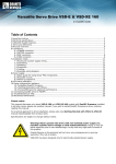
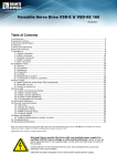
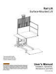
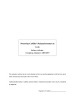
1
“Roy”
Royer Induction Heater Version 3.3
Manual Rev 1.01
This manual valid for units from serial number 001 until the present.
© 2012 Fluxeon Corp
All rights reserved.
No part of this manual may be reproduced in any manner without our express written
permission.
Hey you, Big Guy
Yeah, you, the guy who never reads the instructions. I'm talking to you.
I know what you're thinking – “This box only has three controls so how hard could it be
to operate, right?” It's not hard but it is different.
An induction heater is not a TV remote and you weren't born with the intuition to use it
properly so how 'bout grabbing a cold one, sitting down for a few minutes and reading
this manual? Heck, it's only 27 pages long and with lots of pretty pictures. Bet you can
read it in half an hour. That'll save us both a lot of hassle in the end and you'll learn how
to use your new heater most effectively.
Please Read The Instructions
Page 1 of 27 01/23/13
You'll make us Fluxeonians so happy!
Page 2 of 27 01/23/13
Safety Warnings
• Do not get wet. This unit is not water resistant. If the unit does get wet,
unplug it as quickly as possible and allow to thoroughly dry before trying to use it again. Low
heat (150 deg or less) is recommended to aid drying.
•
This equipment contains sensitive electronics. Do not use this instrument to drive nails, break
rocks or otherwise subject it to excessive shock or vibrations. Try not drop it any more than
necessary.
•
Do not heat pressurized or sealed vessels with this unit. No aerosol cans, air tanks, or any
container that is sealed. Yeah, it's fun to heat things until they blow up but please don't use Roy
for that purpose!
•
Do not heat anything flammable or anything that contains flammable materials or substances.
Automobile gas tanks, for example.
•
Do not use the radio frequency output for anything other than induction heating. No this isn't a
cute little ham radio transmitter!
•
Do not touch the output contacts when the unit is energized. The electricity won't shock you
but RF burns are possible.
•
Do not remove the 3rd wire safety prong. The earth ground is vital to this unit's operation.
•
Do not carry the unit by its cables.
•
Do not open the case. No user-serviceable parts inside. Warranty will be voided if the case is
opened.
•
Do not tamper with the circuit breaker.
•
This unit emits strong radio frequency (RF) energy. Please do not use it around other sensitive
electronic equipment. In the factory, that means don't plug it into the same power serving an
instrumentation, PLC or industrial PC cabinet.
•
Roy's case may get quite hot during extended operation. The over-temperature protection
triggers at 65 deg C (150 deg F). This is quite hot to the touch and can cause mild burns. If
Roy must be operated for an extended period then we suggest setting up a fan to blow on the
case.
•
If any of the cords become frayed or cut, please return the unit to the factory for replacement.
Page 3 of 27 01/23/13
Introduction
“Roy” is a general purpose induction heater that is designed to heat metals, primarily iron and steel
without contacting that metal. It does this without making any contact with the object being heated.
It's power output is adjustable. It contains comprehensive protection against damage from overload or
mis-use. It has a soft limit system whereby the computer warns the user when the unit is about to be
overloaded or become too hot.
It heats with high frequency electromagnetic waves. These waves are similar to the ones that bring you
radio and TV, the only difference being the frequency involved. Roy can do most jobs that a torch can
do but does it without flame or safety hazard. It operates on ordinary 120 volt line current.
Caution: If an extension cord is to be used, it should be a heavy duty cord capable of handling
up to 15 amps with low voltage drop. This would typically be a heavy duty cord of at least 12
gauge wire and no longer than 25 feet.
The Controls
This photo shows all the major features of the heater.
•
Circuit Breaker – The circuit breaker is the black rocker switch that says “on” and “off”. This
breaker controls the power to Roy and also protects it from overload. Turn the breaker on to
prepare for operation. When you turn the unit on all the LEDs will momentarily light while the
unit does its POST (Power On Self Test) to make sure that everything is OK and ready to run.
When the LEDs go out, the unit is ready for operation.
We recommend that the breaker remain off when the unit is not in use. This protects the
electronics from line voltage upsets that could damage the electronics.
•
Push Button – This button controls the heater. It has two modes of operation.
•
Mode 1 – “Push on-Push off.” If you push and then immediately release the button the
heater turns on and latches on. The “heat on” LED will illuminate. If you again press
the button and release it, the heat turns off and the LED goes out.
•
Mode 2 - “Press and hold”. If you press the button and hold it longer than 2 seconds, the
heater enters the “Press and Hold” mode. In this “momentary” mode the heater will stay
on until you release the button and then turn off.
Thus you have two options. “Press On, Press Off” is designed for longer heating operations
so that you don't have to constantly hold down the button. “Press and Hold” is designed
for shorter heating sessions.
Caution:To prevent inadvertent activation, please turn the circuit breaker off
when the unit is not in use.
Page 4 of 27 01/23/13
•
LEDS – There are 5 LEDs on the heater face. They are, from left to right,
•
Green - Indicates power is on. This LED should be on any time the breaker is turned
on and Roy is plugged in. If the green LED fails to come on when the breaker is set to
“ON” then the heater has a problem. Please contact Fluxeon. AFTER you check to
make sure the heater is plugged in, of course!
Amber - “Heat On”. When this LED is on, the heater is generating heat output. This
LED also indicates when the unit is overheating. If the internal electronics become too
hot, this LED will start flashing slowly, about twice a second. The heater automatically
backs down the heat output to control the rise in temperature when it is in this mode. If
the heater continues to get hotter, the unit will trip and the “Fault” light will flash the
“overheat” fault code.
Red – This is the fault indicator LED and also the indicator of near overload. When an
error occurs, this LED flashes a 2 digit code that indicates the fault. A list of fault codes
are contained in Appendix A. If you need to contact Fluxeon for technical support, we
will ask you for the fault code so please note it and write it down. Some codes will
happen fairly often such as 2,1 (heater overload) and 2,2 (heater overcurrent) while
others indicate that something has gone wrong within the heater.
When the load on the heater reaches about 90% of its maximum capability, the fault light
starts blinking slowly, about twice a second. At the same time, the power level knob is
locked in place and is not allowed to increase. The knob may be turned counter-clockwise
to decrease power but any further increase in the clockwise direction is ignored.
Page 5 of 27 01/23/13
The heater can still be overloaded by such things as moving the work coil relative to the
work, allowing the work coil to touch the work, etc. When that happens, the unit trips off on
overload as described above.
•
Power Knob - This knob sets the nominal power of the heater. It does not directly control the
heating level, only the relative power. For most jobs the knob will be set fully to the right (wide
open). Lower power settings are used for delicate and smaller jobs.
Note that the power knob is locked and cannot increase the power output once the heater has
reached about 90% of its full output. This is called a “soft limit” and is designed to allow you
to get nearly as much power as is possible from the heater without the risk of excessive overpower trips.
About Output Power
Roy is designed to output up to 1500 watts under good conditions. By “good conditions” we mean that
the load is well matched to the work coil and the work coil is properly sized. Generally, larger items
with two or three turns of welding cable will draw the full power. A small bolt surrounded by a work
coil consisting of a few turns of 10 gauge wire will not draw full power. It will draw enough power to
heat the object red-hot which is the objective.
This is the nature of a heater that is designed to heat many different items of many different sizes.
Larger induction heaters designed to the specific job at hand have the matching transformers and work
coils custom-designed for the specific load. Obviously a general purpose machine can't have that.
We've designed Roy to heat things ranging from stuck bolts to stuck pulleys and gears to small
gearboxes.
If you plug your Roy into a power meter such as a Kill-A-Watt, you will see power levels ranging from
about 600 watts for small nuts and bolts all the way up to 1700 watts for larger, well matched items.
1700 watts is where the overload trip is set. This range of power is normal.
If you have a special heating need that the standard Roy does not handle well then contact us. We'll
discuss your problem and may be able to build you a custom Roy, customized to your specific needs.
The custom solution may be nothing more than a MatchBox or TransBox.
Page 6 of 27 01/23/13
Power Factor Correction and the MatchBox
Some loads, particularly small ones, exhibit low power factors. That is, lots of current flows through
the work coil but relatively little power is delivered. To address this problem, one may add capacitors
in parallel with the work coil. For example, we can take a small object such as a half inch bolt with a 5
turn work coil from about 500 watts to over 1000 just by adding the correct amount of capacitance.
Determining the right amount of capacitance is somewhat complex and is something that we
recommend you let us do. We sell a “match box” that holds the capacitors and supports optional water
cooling of the work coil.
We will be publishing case studies on our website as experience accumulates. If one of the study work
coils substantially matches your situation then you can use that amount of capacitance and be fairly
close. Otherwise we strongly recommend that you contact us. We'll work with you to establish the
correct tuning.
Page 7 of 27 01/23/13
Familiarization
Now that you've read this manual and have learned what the controls do, it's a good idea to get familiar
with how Roy works before trying to use it on the job. There are two main classes of jobs:
•
Bulk heating.
•
Heating small objects to red heat.
Bulk heating involves heating something like a pulley or a gearbox so that it can be removed or opened
up easier. This usually involves wrapping a couple or three turns of the heavy Litz wire included in the
kit around the object and connecting it to the heater. Welding cable can also be used, though it will get
hot from self-heating.
Bulk Heating
For this familiarization exercise, find something in your shop that is cast iron or steel and weighs
several pounds. The jaws of your vice would be a good object. Wrap about 4 turns of the Litz cable
around this object and connect it to Roy's leads.
With the breaker off, plug in Roy. Turn the heat control knob all the way to the left. Close the breaker.
Observe that all the LEDS come on for a moment and then all but the power LED go out. The unit has
just performed its Power On Self Test (POST) where it verifies that everything inside is OK.
Push the “heat” button and notice that the “heat” LED comes on while the “heat rate” LED starts
flashing slowly. Slowly turn up the heat knob to about half way. Now the “heat rate” LED is flashing
fairly rapidly. Push the “heat” button again to turn the unit off. Carefully feel your vice or whatever
object you selected to heat. Notice how hot it got. Also notice that the heat did not spread beyond the
coils of wire. The localized heating is one of the great things about induction heating.
To learn about the dual mode “heat” button, press it again but this time hold it for 5 or 10 seconds.
This time the heater turned on when you pressed the button but turned off again when you released it.
The button “latches” when you press it for a second or less and becomes a momentary switch if held
longer than that.
Disconnect the Litz cable and put it away.
Red Heat
The other kind of heating involves heating an object to red heat, say,
in preparation for bending it or brazing it. In this type of operation,
the work coil does not touch the work for obvious reasons. We don't
want to melt the work coil.
To demonstrate this mode of operation, find a medium length bolt of
say, 3/8” diameter. Clamp it by its head in your vice. Mount the preformed sleeved work coil to the Roy's leads.
With Roy plugged in and the breaker closed, momentarily press the
“heat” button and turn the power knob all the way to the right. Notice that the “heat rate” LED is
flashing fairly rapidly. The work coil itself is getting hot. Now pass the work coil over the end of the
bolt and hold it there for awhile. The “heat rate” LED speeds up and in a few seconds, the bolt will
Page 8 of 27 01/23/13
first smoke and then get red hot. Move the coil along the bolt. Notice how the area being heated
moves with it. Only the area inside the coil receives much heat.
Press the “heat” button again to turn off Roy, let the work coil cool, disconnect it and put it away.
You've now finished the familiarization exercises and are ready to use Roy to do work.
Operation
Induction heating works by transformer action, causing a heavy current to flow in the work. This
heavy current, combined with hysteresis losses in ferrous materials, causes heat to form in the work
piece. Heat is transmitted by electromagnetic radio waves and not by thermal radiation or conduction.
No heating element is involved.
The coil that receives high frequency current from Roy and goes around the work piece is called the
“work coil”. This coil can be anything from a simple loop(s) of wire to several turns of copper tubing
or heavy solid wire bent to conform to the work piece to be heated.
Operation is simple. The object to be heated is wrapped with several turns of wire, or surrounded by
wire which is attached to the red leads on the heater. The pushbutton is pressed and heating starts. The
amount of power delivered to the work is determined by how many turns of wire are wrapped around
the work and the setting of the power knob. More turns generally equals more power.
Note: It is possible to overload the heater with too many turns. In the case of overload, the unit
will trip initially go into soft limit (red LED flashing slowly) and then if the load increases, it
will trip off-line, the red fault LED will flash the error code 2,1, 2,2 and/or the breaker may trip.
If this happens, remove one or more turns of wire from the work, reset the unit and try again.
You can also control overload with the power control knob. Turn the knob counter-clockwise a
bit to reduce the power setting.
It is best to choose the number of turns so that the heat control knob may remain fully to the
right (maximum output). This causes the heater to run cooler.
Note: When heating something new for the first time, especially when the object is large and/or
involves wrapping several turns of heavy cable around it, we recommend starting the heating
with the heat knob set to the minimum heat (fully counter-clockwise) when the “Heat” button is
pressed. Once the unit is on, gradually turn up the heat knob until the “Heat” LED is on almost
continuously. Starting out low and increasing the power in this manner will prevent nuisance
overload trips.
Wire – Any kind of wire of approximately 10 gauge and larger can be used. Because the wire is in
contact with the device being heated, we recommend the use of THHN, high temperature appliance
wire, Teflon insulated wire or fiberglass insulated wire. Teflon insulated, appliance and fiberglass
insulated wire may be conveniently purchased from Fluxeon. For very high temperature heating jobs,
bare copper wire, either by itself or sleeved with fiberglass/silicone sleeving is the preferred method.
Non-Contact Work Coils – While many heating applications can be done by simply wrapping some
wire directly around the work, sometimes it is necessary for the work coil to not touch the work. This
is especially the case when the work is to be heated red hot.
A good wire for this purpose is 10 gauge hard drawn copper like you can buy at the big box stores for
grounding wire. It should be annealed by heating red hot before trying to wind it around some object
that serves as the form. Otherwise the wire is too hard.
Page 9 of 27 01/23/13
Even better than solid wire is a finely stranded wire
called Litz wire. Litz wire reduces the skin effect of
the high frequency energy traveling through the wire.
This greatly reduces the heating in the work coil.
Every individual strand of Litz wire is insulated from
all the others. The only convenient method of
making contact with the end of the wire is to dip the
wire in a solder pot. The molten solder burns off the
insulation, tins the wire and turns it into one solid
mass.
For that reason, we strongly recommend that you
buy your Litz wire from Fluxeon in pre-cut and tinned lengths.
We make a special form of Litz wire for noncontact use. It contains a single heavy strand of
copper wire in addition to the Litz wire. This solid
strand causes the wire to hold its shape as it is bent
to form a coil or whatever.
In general with a non-contact coil, the more turns
of wire that can be put on the work the better.
Typical is from 4 to 8 turns. Most any object of
the correct diameter can be used for a form. Good forms include water pipe, electrical conduit (EMT)
and wooden dowels. Try to keep the inside diameter of the work coil as close to the outside diameter
of the work as you can. The closer the fit, the tighter the coupling and the faster the heating.
A good technique for winding the work coil is to wind it tightly around the form with the turns
touching and then working a screwdriver between each pair of coils to slightly spread them so that no
adjacent coils touch. This is much easier than trying to wind the coil while maintaining a gap between
turns.
Resetting the Heater
If the computer inside the heater detects a situation that is dangerous to the heater, it will trip the unit
and flash a 2 digit fault code. The meaning of these codes is listed in Appendix A and on the back of
the heater. The heater is non-functional as long as it is in the fault condition.
To reset the heater, either cycle the breaker off and back on or press and hold the heat button until the
“fault” light comes on steady. Release the button. In a couple of seconds, the heater will execute a
POST (all LEDs flash on and then off). It is then ready to operate again.
If you continue to get fault codes other than 2,1 and 2,2, especially when the unit isn't heating, please
contact us at [email protected] for assistance. Some faults require the heater to be returned for
warranty service.
Page 10 of 27 01/23/13
Coupling Techniques
This section demonstrates the various methods of coupling the energy from the heater into the work.
Contact Coupling – This
photo shows a typical
application – heating the hub
of a pulley to loosen it from a
rusted and seized shaft. In
this case, several strands of
small gauge wire are used
instead of one large wire.
(Though we show the small
wire here, a Litz wire would
work even better.) This is not
necessary but the several
small strands makes it easier
to wrap the wire tightly
around the work. The tighter
the wrapping, the more power
that is delivered to the work.
The more turns that are used,
the more power that is
delivered to the work.
Caution: It is possible to
overload the heater by
applying too many turns. If
this happens, simply remove
one or more turns from the
work and try again.
For larger objects, one can use ordinary #4 gauge or similar welding cable. It has a high temperature
neoprene jacket that can withstand heat up to about 500 degrees. The #4 gauge equivalent Litz wire
that Fluxeon sells does a much better job because it does not self-heat very much but sometimes you
have to make do. The same thing holds true for THHN wire. Not the best wire for the job but if it's
handy and something better isn't, then use it.
Page 11 of 27 01/23/13
Non-Contact Coupling – In some
cases, especially when small objects
are to be heated and/or they are to be
heated red hot, non-contact coupling is
used. In this case, the work coil is
would from rigid copper wire or tubing
and placed in close proximity to the
work. When Roy is energized, the
magnetic field from the work coil
causes current to flow in the work and
heat it.
This photo shows a typical example.
The work coil is wound from 10 gauge
bare copper wire. The wire is annealed
by heating it with a torch before
winding to make it easier to wind.
Most anything can be used as a form.
A socket wrench was used in this
instance. The coil should be sized to
fit as closely as possible around the
work. A close fit will result in more
power to the object. Generally, more
turns deliver more power to the load.
Caution: Do not let the adjacent turns of a bare coil
touch each other. This will act as a “shorted turn
secondary and will absorb all the electrical energy.
This photo shows what happens when turns short
together. In this instance, the wire got so hot from heat
radiated from the bolt that one turn sagged into the one
below it, causing the short circuit.
This won't harm Roy but it does stop the heating
process.
This problem can be eliminated by using sleeved wire.
Fluxeon sells the fiberglass/silicone sleeving for this
purpose.
Page 12 of 27 01/23/13
Spiral Coil – For heating large flat surfaces such as sheet metal, a spiral coil may be used.
This photo shows a spiral coil made from copper tubing. It may also be made from solid copper wire
or Litz wire. The number of turns and their spacing determine how much power is delivered to the
work. Generally more turns and closer spacing equal more power.
To use this coil, place a sheet of heat resistant insulating material such as fish paper between the coil
and the work. Energize the heater and optionally move the coil around in small circles to spread out
the heat.
You may make your own coils or you can buy them ready-made from Fluxeon. You may also buy fish
paper from us.
Conformal Heating – For odd-shaped pieces, a custom coil can be wound
around the work so that it conforms to the shape. This permits the heating of
odd shapes. This type of winding – using the appropriate heat resistant wire,
of course – would be useful , for example, for brazing a carbide cutter onto
the end of a tool steel square.
Page 13 of 27 01/23/13
Heating Non-Ferrous Metals
Ferrous magnetic metals (iron, steel and magnetic stainless) heat the best with induction heating. Nonmagnetic stainless steel less well. The light metals (aluminum, zinc, tin, etc) heat moderately well,
aluminum being the worst because of its high electrical conductivity. Copper heats the poorest because
it conducts electricity so well. It requires much higher currents to cause a given amount of heating in
aluminum and copper than it does steel.
The standard Roy will do a fair job on copper
and a fair to good job on aluminum. To get the
best results, get the work coil as close to the
work as possible and use as many turns as
possible. Here is a photo of a soldering job
being done by the standard Roy.
The coil liner that prevents the work from
contacting and shorting out the work coil is the
high temperature “slot paper” that we sell for
such purposes. It does not char or discolor at
soldering temperatures.
If you consistently need to heat these metals,
then please contact us. A “match box” and a
water cooled coil will do a much better job in
most situations. As mentioned earlier in this
manual, our assistance will normally be needed
to properly set up the match box.
Bare vs Insulated
In most instances the work coil can be made of bare copper, either wire or tubing. In some cases,
though, the work coil needs to be insulated because the work might contact the coil and short against
the turns. Insulated wire should always be used when the work coil is wound around and is in contact
with the work.
There are two options for insulation.
•
Insulated wire
•
Sleeved bare wire
Insulated wire such as THHN, high temperature appliance wire and Teflon insulated wire can be used
at moderate temperatures, up to a few hundred degrees. Fiberglass insulated wire will go a little higher.
Above that, either bare or sleeve insulated wire must be used.
The basic sleeving that we supply and recommend is a fiberglass/silicone composite. This sleeving is
used for motor winding and other high temperature applications. It is good up to red heat, though the
silicone degrades at the higher temperatures so the life is short.
Page 14 of 27 01/23/13
This photos shows a coil made of bare wire that has been sleeved with the fiberglass/silicone sleeving.
The sleeving should be considered a consumable since at high temperature its life is somewhat short.
Therefore be sure to keep an adequate supply on hand. Fluxeon sells this sleeving in various sizes.
It is useful to line the inside of the coil with high-temperature sheet insulation, such as ceramic or
fiberglass paper, or mica. Using these materials will protect the coil and the sleeving very well.
Fluxeon also sells custom-designed sprial coils. These coils are made to order and are normally coated
with a tough ceramic insulating and heat reflecting coating that greatly enhances performance. Contact
[email protected] for more information.
Duty Cycle
Roy is designed for MRO (Maintenance, Repair, Overhaul) type jobs and as such is not designed for
high duty cycle or repetitive heating tasks. It is designed to perform a heating cycle and then be
allowed to cool for some time before being used again. Think of Roy as you would an inexpensive
stick welder. These welders typically have duty cycles of 20% at full output. Roy is better than that
but he is not designed for even 50% duty cycle. Fluxeon offers heaters with higher duty cycle ratings
but they naturally cost more than this simple utility heater.
Thermal protection – Roy is equipped with thermal protection. The thermal protection turns off Roy
when the case temperature reaches approximately 55 deg C. If the unit trips on thermal overload then
Page 15 of 27 01/23/13
the “fault” LED will flash either 1,1 or 1,2 depending on what overheated. See Appendix A for what
these codes mean. After the unit is allowed to cool for awhile, reset the unit as described above.
Power Ramp Back - At a case temperature of about 50 deg C, Roy starts ramping back the power in
an effort to prevent an over-temperature trip. The power will continue to ramp back until the
temperature no longer rises. If this amount of power does not supply enough heat, simply turn the unit
off but leave the breaker on so that the fans can cool the unit.
External fans blowing on Roy's fins will greatly extend the run time. With high velocity air on both
sets of fins, the duty cycle approaches 100%.
Heating Lunch
We include this section because we know you're going to try it.
We want you to do it safely.
WARNING*WARNING*WARNING*WARNING
The can to be heated MUST be opened before
applying any heat from Roy. We have a video
that is posted on the Fluxeon web site showing
this can of water being brought to boil on the
sides in about 1 second! It could build up
enough pressure to burst a closed can and spray
you with hot contents in 5 seconds or less.
WARNING*WARNING*WARNING*WARNING
The safe way to do this is as follows:
•
Fully Open the can. That doesn't mean poke a few holes in it. That means remove the lid just
as shown above.
•
Wrap 4 or 5 turns of wire around the length of the can (spread out more than is shown in the
photo) and secure with tape or cable ties.
•
Set the power control all the way to minimum (fully counter-clockwise).
•
Press the heat on button.
•
Gradually turn up the power until the contents are sizzling against the sides. The heat rate LED
will be blinking maybe 4-5 times a second.
•
Grasp the can with a gloved hand (Caution: hot!) and rapidly stir with a spoon or fork using
the other hand. Even at modest power, the heat is being delivered to the food is vastly faster
than it could ever be done on a stove so the contents are going to get hot fast! Faster than you'll
be prepared for during your first few attempts.
•
When the food is hot enough, turn the unit off, remove the coil and enjoy your meal.
Page 16 of 27 01/23/13
•
To boil water, fill a can such as pictured above with water. Turn on Roy, press the heat button
and turn the heat control wide open. This will bring a can of water to a rolling boil in about 45
seconds.
Naturally, you may also heat food in a cast iron or steel pot. Aluminum doesn't work so well because
it is so electrically conductive. Wrap a few turns of cable around the outside and proceed as above.
Note that the sides and not the bottom get hot so vigorous stirring is necessary.
Please note that Fluxeon does not recommend cooking with Roy but since you're probably going
to try it anyway, we want you to know how to do it safely. This page is not an endorsement of Roy
Cooking.
Page 17 of 27 01/23/13
Technical Support
The Fluxeon crew is dedicated to supporting you the customer. The best way to get technical support
is to email [email protected]. For non-technical support questions, email [email protected]. We
try to respond to requests within the hour during business hours and within a day regardless.
For telephone support, call us at 901-290-3589. This call goes directly into voice mail that in turn
pages the person doing support at that moment. Someone will get back to you as quickly as possible.
We are a small company and telephone support takes up a lot of time so if your problem isn't a genuine
emergency, please use the email support. Even when you telephone us, the support ticket is probably
going to end up back in email so that you can send us photos and such, so you might as well start with
email in the first place.
Returns
If you need to return your unit for service (in warranty or out) then you must contact us for an RMA
number. Email is the best method of contact. Write the RMA number on the outside of the package in
large numbers so that it is easily visible. The RMA number lets us track your problems and associate
them with the machine when it arrives. Packages without RMA numbers may be returned to sender.
Limited Warranty
Fluxeon warrants that Roy will be free from defects in workmanship and materials for a period of 1 year from
the original sell date. If you bought Roy directly from us then we have a record of your purchase date. If you
bought it from a distributor, keep your receipt. You must be able to prove your purchase date to obtain warranty
service. If you buy the unit used, be sure to get a copy of the original receipt. The warranty transfers with the
unit but is still only valid for 1 year from the original sell date. If you did not buy your Roy from us and cannot
produce a receipt then the warranty period is 1 year from the date of manufacture.
If a warranty replacement becomes necessary, Fluxeon, at its sole discretion, may supply a refurbished, like-new
unit to replace the old one. If a warranty replacement is necessary, the warranty shall run the longer of either the
remaining original warranty or 90 days.
Your warranty is void if you break the seals on the case or if you abuse the unit. Our judgment on abuse is final.
We understand that Roy is likely to lead a rough life in the MRO environment. That's why we built it so rugged
and why we're lenient in defining abuse. Lenient but not push-overs. If you use Roy to chock the wheels of a
semi truck, don't expect us to replace the flattened mass for free.
We understand that you may be curious as to what is inside Roy. That's why we have photos of the interior on
our web site. Go to http://www.fluxeon.com to see the photos. We sealed the unit because there are lethal
voltages inside and we don't want you messing around and getting hurt. We are pretty flexible on our warranty
adjustments but there will be no exceptions ever! If the tamper seals are violated.
THIS WARRANTY IS YOUR ONLY REMEDY. ALL OTHER WARRANTIES - WHETHER EXPRESS,
IMPLIED OR STAUTORY - INCLUDING IMPLIED WARRANTIES OF FITNESS FOR A PARTICULAR
PURPOSE OR MERCHANTABILITY, ARE HEREBY DISCLAIMED. MANUFACTURER SHALL NOT BE
LIABLE FOR ANY SPECIAL, INDIRECT, INCIDENTAL OR CONSEQUENTIAL DAMAGES OR LOSSES,
ARISING FROM ANY CAUSE OR THEORY. Since some states or countries do not allow the exclusion or
limitation of an implied warranty or of incidental or consequential damages, this limitation of liability may not
apply to you.
Page 18 of 27 01/23/13
Appendix A
Fault Codes
The computer inside Roy is designed to look after him and protect him from various conditions that
could damage him. When conditions become such that operation is not safe, the computer turns Roy
off and flashes fault codes on the “Fault” (RED) LED. These codes consists of two digits. First digit is
flashed, a short pause, the second digit is flashed, a long pause and then it repeats as long as the power
is turned on. If you've ever dumped fault codes from an automobile's computer, you'll be right at home
here.
For example, suppose the problem was simple overload. That is, you applied too much load to the unit.
That's fault code 2,1, the sequence would be this
flash—flash--_-flash-----flash--flash----flash----- and so on.
These codes are very important for us to aid you when you need technical support. If you continue to
get a fault code, be sure to write it down before contacting Fluxeon.
To reset the machine and clear the fault, turn the breaker off and back on.
Page 19 of 27 01/23/13
Here is the table of codes and their meaning.
Code Number Blink Code
Cause
Remedy
1
1,1
The main Royer transistors have exceeded their allowable
temperature
Allow unit to cool then cycle power
2
1,2
Main heatsink has exceeded its allowable temperature
3
1,3
No load detected when heater “ON” button was pressed.
Allow unit to cool then cycle power
Check connections. Cycle power. If problem persists,
contact Fluxeon
4
1,4
Voltage regulator may be malfunctioning.
Cycle power. If problem persists, contact Fluxeon
5
1,5
6
1,6
Voltage regulator may be malfunctioning.
Cycle power. If problem persists, contact Fluxeon
7
2,1
Inverter is drawing too much current
Possible overload. Cycle power and reduce the load. If
problem persists, contact Fluxeon
8
2,2
Voltage regulator may be malfunctioning.
Cycle power. If problem persists, contact Fluxeon
9
2,3
Voltage regulator may be malfunctioning during POST.
Cycle power. If problem persists, contact Fluxeon
10
2,4
Potential problem with voltage regulator or inverter
Cycle power. If problem persists, contact Fluxeon
11
2,5
inadequate line voltage, operating on too small an
extension cord, other cause for low incoming voltage
Cycle power. If problem persists after fixing line voltage
problem, contact Fluxeon
2,6
Reduce the load on the heater by turning down the heat
control knob or removing turns. Cycle the breaker and try Cycle power. If problem persists after fixing overload
again
problem, contact Fluxeon
12
Page 20 of 27 01/23/13
Appendix B
Diagnostic Mode
Roy has a special diagnostic mode that will help us with troubleshooting problems. Roy keeps track of
various events such as fault codes and will dump them via the “fault” LED identically to the format
described above for automatic fault code reporting.
Diagnostic mode is entered by holding the pushbutton while applying power or any time during
the POST. Here is the step-by step.
1. Turn the circuit breaker OFF.
2. Hold down the HEAT button
3. While holding the button, turn on the circuit breaker
4. Continue holding the button until the FAULT LED comes on continuously.
5. Release the button.
6.
In about a second, the LED will start flashing the code.
(If you accidentally get in this mode by pressing the button too quickly after turning on the power,
simply turn off the breaker for a moment and turn it back on.)
You'll know you're in Diagnostic Mode when the Fault LED comes on continuously. The first submode is the serial number dump sub-mode.
Serial Number Dump
The serial number is a 10 digit number. When you release the pushbutton while the LED is solid on,
the unit will flash the serial number one digit at a time and then repeats the dump until the power is
turned off or the pushbutton is held in again. The digit “0” is represented by a short blink. So if the
serial number is:
0000001234
The output would be
>short blink< 0
long delay
>short blink< 0
long delay
>short blink< 0
long delay
>short blink< 0
long delay
>short blink< 0
long delay
>short blink< 0
Page 21 of 27 01/23/13
long delay
>long blink<
digit 1
long delay
>long blink<
digit 2
delay
>long blink<
long delay
>long blink< digit 3
delay
>long blink<
delay
>long blink<
long delay
>long blink<
digit 4
delay
>long blink<
delay
>long blink<
delay
>long blink<
longer delay
start over from the top
If at any time during the above sequence, you press and hold the pushbutton again, the red Fault LED
will come on solid again. When you release the button you will be in the Firmware Revision Number
Dump Mode.
Firmware Revision Number Dump
The firmware number consists of 6 or 8 digits in the format
aa.bbccdd
where
aa -
major revision code
bb -
minor revision code
cc -
feature revision code
dd -
special revision code.
Page 22 of 27 01/23/13
The digit zero is represented by a very short blink. So if the serial number is
01.0200
The sequence would be
>short blink<
delay
>long blink<
delay
>short blink<
delay
>long blink<
>long blink<
delay
>short blink<
delay
>short blink<
longer delay
repeat over from the top.
The decimal point is not flashed and is implied after the second digit. Normally what you'd do is enter
this sub-mode and then write down the flash count as they happen. Then let the sequence repeat to
check yourself. Finally, put the decimal after the second digit.
If at any time during the above sequence, you press and hold the pushbutton again, the red LED will
come on solid again. When you release the button you will be in the Fault Count Dump Mode.
Fault Count Dump Mode
Roy keeps track of faults as they happen and store the number of times each fault happens in nonvolatile memory. During the diagnosis of a problem, we may ask you to dump this memory. It dumps
exactly the same as above, the only difference being that there are 16 slots (or more depending on
firmware revision) and up to 256 blinks in each slot. If your machine has had lots of faults, then this
procedure will be one to pull up a comfortable chair along with a cup of java 'cuz you'll be there
awhile.
Putting Roy in any of these modes is perfectly OK and does not change a thing with him so feel free to
experiment and get used to the way the flasher works. That way you'll also recognize when you
accidentally get into diagnostic mode by pressing the heat button before the POST is finished (all the
LEDS have extinguished after power up.
Page 23 of 27 01/23/13
Specifications
Rated input power
1500 watts
Rated input Current
15 amps
Operating voltage
120 VAC +5%
Operating Frequency
60-80 kHz, depending on load
Ambient operating temperature
0 – 120 deg F
Storage Temperature
-10 – 160 deg F
Duty cycle
Approximately 30%. 3 – 5 minutes on, 7 – 10
minutes cooling time.
Maximum operating temperature
65 deg C.
Page 24 of 27 01/23/13
Appendix C
Auxiliary Connector
The Roy contains an auxiliary connector similar to this.
This connector is designed to permit the remote control of Roy and to discern its status. The pinouts
are as follows:
Pin Number
Function
1
Heat on indication
2
Power Level Out
3
Fault Out
4
Isolated Ground
5
Analog power control signal *
6
+15 volts, not isolated
7
+15 volts Isolated **
8
Pushbutton in
9
Spare out
*
Use of this signal requires the purchase of the optional analog isolation control board
**
This is designed to supply anode power to LEDs that are driven by the outputs
Page 25 of 27 01/23/13
The unit may be turned on by connecting pins 4 and 8 together. Technically, pin 8 is active low. That
is, it should be pulled low relative to the isolated ground to energize the machine. It is expected that
a contact closure or opto-isolator will be used. Pin 8 is +15 volts high when not activated.
Note: There is a 1uF capacitor connected in parallel with pins 4 and 8. This is designed to provide a
little surge of current when the contact is closed to prevent an insulating film from building up on the
switch. If you use a solid-state switch, be sure it can handle the surge current.
The various outputs are open collector (60ma max) outputs hooked in parallel with the front panel
LEDs. They are intended to permit the use of LEDs on a remote control. They may also be fed into a
computer or PLC but the software will have to contend with the same flashing as the LEDs do.
The opto-couplers are protected against reverse polarity by a reverse-biased diode in parallel with the
output transistor. This diode is rated at 1 amp. Please be careful to watch your polarity, as diodes
usually fail shorted.
Page 26 of 27 01/23/13
Office Address:
Fluxeon Corporation
4181 Avati Dr
San Diego, CA 92117
901-290-3589
Fax 815-550-1047
[email protected]
www.fluxeon.com
Page 27 of 27 01/23/13