1
Lumenera USB Camera
User’s Manual
Release 5.0
Lumenera Corporation • 7 Capella Court, Ottawa, ON, Canada • K2E 8A7 • (t) 1.613.736-4077 • (f) 1.613.736-4071 • www.lumenera.com
The contents of this document may not be copied nor duplicated in any form, in whole or in part, without prior written consent from Lumenera Corporation. Lumenera makes no
warranties as to the accuracy of the information contained in this document or its suitability for any purpose.
The information in this document is subject to change without notice.
Copyright © 2008 Lumenera Corporation. All rights reserved.
Sept 2008
Release 5.0
Lumenera USB Camera
User’s Manual
License Agreement (Software):
This Agreement states the terms and conditions upon which Lumenera Corporation
("Lumenera") offers to license to you (the "Licensee") the software together with all
related documentation and accompanying items including, but not limited to, the
executable programs, drivers, libraries, and data files associated with such programs
(collectively, the "Software").
The Software is licensed, not sold, to you for use only under the terms of this
Agreement.
Lumenera grants to you the right to use all or a portion of this Software provided that the
Software is used only in conjunction with Lumenera's family of products.
In using the Software you agree not to:
a) decompile, disassemble, reverse engineer, or otherwise attempt to derive the source
code for any Product (except to the extent applicable laws specifically prohibit such
restriction);
b) remove or obscure any trademark or copyright notices.
Limited Warranty (Hardware and Software):
ANY USE OF THE SOFTWARE OR HARDWARE IS AT YOUR OWN RISK. THE
SOFTWARE IS PROVIDED FOR USE ONLY WITH LUMENERA'S HARDWARE AND
OTHER RELATED SOFTWARE. THE SOFTWARE IS PROVIDED FOR USE "AS IS"
WITHOUT WARRANTY OF ANY KIND. TO THE MAXIMUM EXTENT PERMITTED BY
LAW, LUMENERA DISCLAIMS ALL WARRANTIES OF ANY KIND, EITHER EXPRESS
OR IMPLIED, INCLUDING, WITHOUT LIMITATION, IMPLIED WARRANTIES OR
CONDITIONS OF MERCHANTABILITY, QUALITY AND FITNESS FOR A
PARTICULAR PURPOSE. LUMENERA IS NOT OBLIGATED TO PROVIDE ANY
UPDATES OR UPGRADES TO THE SOFTWARE OR ANY RELATED HARDWARE.
Limited Liability (Hardware and Software):
In no event shall Lumenera or its Licensor's be liable for any damages whatsoever
(including, without limitation, incidental, direct, indirect, special or consequential
damages, damages for loss of business profits, business interruption, loss of business
information, or other pecuniary loss) arising out of the use or inability to use this
Software or related Hardware, including, but not limited to, any of Lumenera's family of
products.
Product Warranty
Lumenera Corporation warrants to the original purchaser that our cameras are
guaranteed to be free from manufacturing defects for a period of one (1) year from the
original date of purchase.
Page i
Copyright © 2008
Lumenera USB Camera
User’s Manual
Release 5.0
Should the unit fail during the warranty period, Lumenera will, at its option, repair or
replace the failed unit. Repaired or replaced units will be covered under warranty for the
remainder of the original one (1) year warranty period.
This warranty does not apply to units that, after being inspected by Lumenera, have
been found to have failed due to customer abuse, accidents, mishandling,
tampering/alteration, improper installation, improper power source, negligence, opening
of the enclosure, or if the serial number has been removed or damaged. This warranty
does not cover labor or incurred charges required in removing or installing the unit, any
business interruption, loss of profits/revenues, or any consequential damages.
Units returned to Lumenera beyond the warranty period will be repaired, if possible, and
all appropriate material and labor charges will apply.
Any returning product, specifically those being returned under warranty, must follow the
Returned Material Authorization (RMA) process. Any units being returned are to be
properly packaged (in original packing – if possible). Lumenera will not cover damage
sustained in shipping due to improper packing.
For RMA instructions, please refer to our website at www.lumenera.com.
RoHS/WEEE Compliance Statement
The Restriction of Hazardous Substances in Electrical and Electronic Equipment (RoHS)
Directive was passed into law by the European Union (E.U.). It affects manufacturers,
sellers, distributors and recyclers of electrical and electronic equipment containing lead,
cadmium, mercury, hexavalent chrome, polybrominated biphenyl (PBB) and
polybrominated diphenyl ether (PBDE). After July 1, 2006 the use of these materials will
be banned in new products sold in Europe. The RoHS Directive complements the WEEE
Directive. China is expected to adopt similar legislation within a similar timeline.
The Waste Electrical and Electronic Equipment Directive (WEEE) aims to reduce the
waste arising from electrical and electronic equipment and to improve the environmental
performance of all those involved in the life cycle of these products.
Lumenera is committed to protecting people and the environment and we are working on
identifying any materials used in our processes that could pose a potential hazard to our
employees, customers or the environment.
For this reason we are committed to have all our products comply with the RoHS and
WEEE directives. We are constantly improving our compliance with these directives. For
more information on our compliance or to track our progress please refer to our website.
Copyright © 2008
Page ii
Lumenera USB Camera
User’s Manual
Release 5.0
Table of Contents
LICENSE AGREEMENT (SOFTWARE): ................................................................................. I
LIMITED WARRANTY (HARDWARE AND SOFTWARE): ........................................................... I
LIMITED LIABILITY (HARDWARE AND SOFTWARE): .............................................................. I
PRODUCT WARRANTY ..................................................................................................... I
ROHS/WEEE COMPLIANCE STATEMENT ..........................................................................II
INTRODUCTION............................................................................................................. 1
1.1
THE LUMENERA USB CAMERA FAMILY .................................................................. 1
INSTALLING AND USING THE CAMERA..................................................................... 2
2.1
CAMERA AND SOFTWARE INSTALLATION ................................................................ 2
2.1.1
Minimum System Requirements ................................................................ 2
2.1.2
Camera Power Requirements ................................................................... 2
2.1.3
Installation Procedure ................................................................................ 2
2.1.4
Software Upgrade Procedure .................................................................... 4
2.2
TECHNICAL ASSISTANCE ...................................................................................... 4
2.3
USING THE INSTALLED SOFTWARE ........................................................................ 5
2.3.1
Drivers & INF ............................................................................................. 5
2.3.2
DirectShow Filters...................................................................................... 5
2.3.3
Application Software .................................................................................. 5
2.3.4
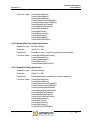
Software Development Kit (SDK)............................................................... 6
2.3.5
Documentation .......................................................................................... 6
2.3.6
Driver Only Installation Packages .............................................................. 6
2.4
USING LUCAM CAPTURE ...................................................................................... 7
2.4.1
Menu Items................................................................................................ 7
2.4.2
Buttons and Interface Controls .................................................................. 9
UNDERSTANDING YOUR CAMERA........................................................................... 13
3.1
SHUTTER TYPES ............................................................................................... 13
3.1.1
Rolling Shutter ......................................................................................... 13
3.1.2
Half Global Shutter .................................................................................. 13
3.1.3
Global Shutter.......................................................................................... 14
3.2
SCANNING MODE .............................................................................................. 15
3.2.1
Progressive Scan..................................................................................... 15
3.2.2
Interlaced Scan........................................................................................ 15
3.3
USE OF FLASH OR STROBE ................................................................................ 16
3.3.1
Flash with Rolling Shutter ........................................................................ 17
3.3.2
Flash with Half Global Shutter ................................................................. 17
3.3.3
Flash with Global Shutter......................................................................... 17
3.4
CAMERA MODES ............................................................................................... 17
3.4.1
Streaming Video ...................................................................................... 18
3.4.2
Snapshot (Asynchronous Trigger) ........................................................... 18
Page iii
Copyright © 2008
Lumenera USB Camera
User’s Manual
Release 5.0
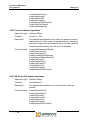
3.5
DATA FORMAT ................................................................................................... 18
3.6
SUBWINDOWING, SUBSAMPLING & BINNING ......................................................... 21
3.7
EXTERNAL I/O INTERFACE .................................................................................. 21
3.7.1
Standard LuCam Camera GPIO Interface Description ............................ 21
3.7.2
LuCam Large Format Camera GPIO Interface Description...................... 23
3.7.3
GPIO Descriptions and Signal Definitions for Mini Cameras ................... 24
3.7.4
Signal Definitions for All Cameras............................................................ 26
3.7.5
Taking a Single-Frame Snapshot with the Camera.................................. 27
3.8
EXTERNAL POWER............................................................................................. 28
3.9
LENS MOUNT .................................................................................................... 29
3.10 CAMERA IDS ..................................................................................................... 29
APPLICATION PROGRAMMING INTERFACE USER’S GUIDE ................................. 31
4.1
GENERAL OVERVIEW ......................................................................................... 31
4.2
BASIC TASKS .................................................................................................... 31
4.2.1
Connecting and Disconnecting ................................................................ 31
4.2.2
Query the Camera ................................................................................... 32
4.2.3
Preview Video .......................................................................................... 32
4.2.4
Adjusting the Video .................................................................................. 32
4.2.5
Configuring Video Format ........................................................................ 33
4.2.6
Grab Video Data ...................................................................................... 33
4.2.7
Take a Snapshot (or many)...................................................................... 34
4.2.8
Processing Images .................................................................................. 34
4.2.9
Save Image to Disk.................................................................................. 34
4.2.10 Setting and Getting Camera Properties ................................................... 35
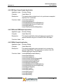
4.3
ADVANCED TASKS ............................................................................................. 36
4.3.1
Manage Your Own Video Display Window............................................... 36
4.3.2
Custom Color Correction Matrix............................................................... 36
4.3.3
Custom Look-Up-Tables (LUT) ................................................................ 37
4.3.4
Video Callback functions.......................................................................... 37
4.3.5
Snapshot Callback Functions................................................................... 37
4.3.6
Multiple Camera, Simultaneous Image Capture....................................... 37
4.3.7
Non-Volatile User Accessible Camera Memory ....................................... 38
4.4
SDK SAMPLE CODE DESCRIPTIONS .................................................................... 39
4.4.1
AutoLens Sample Application .................................................................. 39
4.4.2
AVISample Sample Application ............................................................... 40
4.4.3
BlankCamera Sample Application............................................................ 40
4.4.4
Callback Sample Application.................................................................... 41
4.4.5
CaptureToFile Sample Application........................................................... 42
4.4.6
ClickCrop Sample Application.................................................................. 43
4.4.7
CSharp Sample Application ..................................................................... 43
4.4.8
DirectShow Callback Sample Application ................................................ 44
4.4.9
DirectX Sample Application...................................................................... 44
4.4.10 DirectX Snapshot Sample Application ..................................................... 44
4.4.11 DualSlope Sample Application................................................................. 44
Copyright © 2008
Page iv
Release 5.0
Lumenera USB Camera
User’s Manual
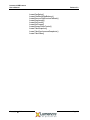
4.4.12
4.4.13
4.4.14
4.4.15
4.4.16
4.4.17
4.4.18
4.4.19
4.4.20
4.4.21
4.4.22
4.4.23
4.4.24
4.4.25
4.4.26
4.4.27
4.4.28
4.4.29
4.4.30
4.4.31
4.4.32
4.4.33
4.4.34
4.4.35
4.4.36
DX Control Net Sample Application ......................................................... 45
EnumFrameRates Sample Application .................................................... 45
FastSynchSnaps Sample Application ...................................................... 45
Flipping Sample Application .................................................................... 46
FrameRate Sample Application ............................................................... 46
Get16BitInfo Sample Application ............................................................. 47
GetRanges Sample Application ............................................................... 47
GPI Event Signalling Sample Application ................................................ 47
GpioTest Sample Application .................................................................. 47
Histogram Sample Application................................................................. 48
HwTrigCount Sample Application ............................................................ 49
InfinityTest Sample Application................................................................ 49
Lucam Capture Sample Application......................................................... 50
LucamX Sample Application.................................................................... 50
MonoCheck Sample Application .............................................................. 51
MultiSnapshot Sample Application .......................................................... 52
PermStorage Sample Application ............................................................ 52
ResetAndFF Sample Application ............................................................. 52
ScrollingPreview Sample Application....................................................... 53
Snapshot Sample Application.................................................................. 53
Threshold Sample Application ................................................................. 54
VB Picture Flip Sample Application ......................................................... 54
VB Sync Snaps Sample Application ........................................................ 55
VBlucamCOMSample Application ........................................................... 55
VBNet Sample Application....................................................................... 55
Page v
Copyright © 2008
Release 5.0
Lumenera USB Camera
User’s Manual
1
Introduction
1.1 The Lumenera USB Camera Family
Lumenera USB Cameras provide a quick and easy means of displaying and
capturing high quality video and images on any USB 2.0 equipped desktop,
laptop or embedded computer.
Designed with flexibility in mind, each camera model has its own distinct
advantage over the others, whether speed, resolution, image quality, sensitivity
or price. Because they are USB based, there is no need for a frame grabber.
Instead, a single cable provides power, full command and control and data
transfer at speeds of up to 24 MB/s (Lu series) or 48 MB/s (Lw series).
All cameras have a provision to be externally powered for cases where the USB
cable does not supply power (e.g. some USB cards on laptop computers.)
All cameras share the same simple, yet powerful API allowing easy migration
from one camera to another. Both board-level and enclosed cameras are
available. All cameras also have an optional external interface header for
hardware input and output signals and on-board memory for image buffering.
Page 1
Copyright © 2008
Lumenera USB Camera
User’s Manual
Release 5.0
2
Installing and Using the Camera
2.1 Camera and Software Installation
The Lumenera USB 2.0 High-Speed camera you have just purchased is
designed to operate out of the box with minimal set-up.
Note: Prior to plugging the camera into the computer, you must first install the
software.
The software can be found on the CD-ROM that shipped with your product.
2.1.1 Minimum System Requirements
•
Windows 2000 (Service Pack 4), or
•
Windows XP (Service Pack 2)
•
450 MHz Pentium III or higher (compatible)
•
128 MB RAM
•
USB 2.0 Port.
Note: A USB 2.0 Port is required. The camera will not work on a
standard USB 1.1 port.
2.1.2 Camera Power Requirements
The camera can typically run off of the USB bus. In some cases and/or camera
models, there may be a need to externally power the camera. Please refer to
Section 3.8 for more information on selecting the appropriate power supply for
your camera. If an incorrect external power supply is used, it could damage the
camera and void your warranty.
2.1.3 Installation Procedure
The Lumenera USB 2.0 High-Speed camera you have just purchased is
designed to operate straight out of the box. However, prior to plugging the
camera into the computer it is recommended that you first install the
software, which is included on the CD-ROM that shipped with your product.
Follow the steps below for simple installation:
Copyright © 2008
Page 2
Lumenera USB Camera
User’s Manual
Release 5.0
Installation Steps:
1. If you are using a 3rd party USB 2.0 PCI add-in card, please ensure
the add-in card is properly installed on your computer before
proceeding.
2. If you have purchased a developers kit and are using the supplied
USB 2.0 PCI add-in card, the drivers are built-in when using Windows
XP with Service Pack 2. Windows 2000 users should first upgrade to
Service Pack 4, and then go to the Windows upgrade site
(http://windowsupdate.microsoft.com) to obtain the USB 2 Host
controller drivers.
3. You must ensure you are logged into the computer with administrator
privileges prior to continuing the installation.
4. Close all application software that is running and then insert the Lumenera
Installer CD into your CD-ROM drive.
5. Double-click on “setup.exe”, or wait a few moments for the auto-play
function to load the setup program automatically.
6. Follow the onscreen prompts to install the software drivers and user
application.
7. After the software has been installed, plug the USB 2.0 Camera into a free
USB 2.0 High-Speed port.
8. Windows 2000 & XP Users:
a. The Window’s New Hardware Wizard will pop-up detecting a new
“Lumenera Unconfigured Device”. Select “Install the software
automatically” from the options that are presented to you and click
Next. A warning may appear notifying you that the drivers have not
been digitally signed by Microsoft. Click Continue Anyway to continue
with the driver installation. Then click Finish to install the drivers.
b. After a few seconds the Window’s New Hardware Wizard will pop-up
again (if it doesn’t, unplug and re-plug the camera device), detecting a
“Lumenera Mega 092 Camera” device. Select “Install the software
automatically” from the options that are presented to you and click
Next. A warning may appear notifying you that the drivers have not
been digitally signed by Microsoft. Click Continue Anyway to continue
with the driver installation. Then click Finish to install the drivers.
(Please Note: Depending on the camera model purchased the string
“Mega 092” may be different than noted above.
c. Important: Windows will ask you to re-run these steps each time you
plug the camera into a new USB 2.0 port. You must have administrator
privileges the first time the camera is used on any given USB 2.0 port.
Page 3
Copyright © 2008
Lumenera USB Camera
User’s Manual
Release 5.0
You may wish to repeat these installation steps at this time for all USB
2.0 ports.
9. Restart your computer
10. Run the LuCam Capture application software from your Start menu to
control the camera.
2.1.4 Software Upgrade Procedure
The Software Upgrade procedure is similar to the original software installation. If
you have installed a previous version of the software you should uninstall it prior
to running the Software Upgrade.
Note: Should the Uninstall Script identify that a reboot is required, please ensure
that you perform this step by rebooting your computer before installing the
Software Upgrade. Failure to do so could cause difficulties with any future
installations.
If you run the Software Upgrade without uninstalling the older version, it will
uninstall it for you. You will need to rerun the Software Upgrade to install the new
software.
2.2 Technical Assistance
If you need assistance with the installation or use of the software, or, if you need
help with general camera operation, please contact the Technical Assistance
Centre (TAC) via email at:
[email protected]
or by phone at +1-613-736-4077 (press 2 from the auto attendant)
To obtain the latest software release and other technical information you may
visit our technical support website at:
http://www.lumenera.com/support/index.php
Our support website contains technical information available to the general public
such as Frequently Asked Questions (FAQ’s). For our Lumenera customers we
provide a Knowledge Base with more product specific solutions and a Download
Centre for customers to obtain the most recent software releases.
As a customer, you will need to provide the TAC with some basic information to
gain access to the customer Knowledge Base and the Download Centre. Please
provide the following details via email to [email protected] to obtain a
user name and password:
•
Your name, Company Name, address and telephone number
Copyright © 2008
Page 4
Lumenera USB Camera
User’s Manual
Release 5.0
•
Your camera model and serial number
•
Your purchase information (e.g. did you purchase from an OEM or
distributor?)
•
Your SDK password that was provided to you and printed on the CD
jacket.
Upon providing the above information, you will receive your access information
via email from a TAC representative.
2.3 Using the Installed Software
All of the necessary software and device drivers are contained in an installation
program on the CD-ROM that comes with the camera.
The following files are installed when you run the installation program:
2.3.1 Drivers & INF
Files with a .sys extension are copied to …\SYSTEM32\DRIVERS folder in the
standard Windows folder on your system. There are two of these files for each
camera model supported by the software. The names of these files are
LucamXXX.sys and LuldrXXX.sys or LwcamXXX.sys and LwldrXXX.sys (the
XXX represents the 3 digit camera ID number.)
Files with a .inf extension are copied to …\INF folder in the standard Windows
folder of your system. There are up to two of these files for each camera model
supported by the software. The names of these files are LucamXXX.inf and
LuldrXXX.inf or LwcamXXX.inf and LwldrXXX.inf (the XXX represents the 3 digit
camera ID number.)
2.3.2 DirectShow Filters
Several DirectShow (or WDM) related files are installed in the …\SYSTEM folder
in the standard Windows folder on your system. These files all have a .ax
extension. Their names are:
Lutf.ax
Lucustom.ax
Lustrcfg.ax
2.3.3 Application Software
The LuCam Capture application (LuCam.exe) is installed in the directory selected
during the installation process. The default location is:
C:\Program Files\Lumenera Corporation\LuCam Software
Page 5
Copyright © 2008
Lumenera USB Camera
User’s Manual
Release 5.0
A shortcut to this application is added to the Start Menu at the location selected
during installation. The default location is:
Start > Programs > Lumenera > LuCam > LuCam.exe
2.3.4 Software Development Kit (SDK)
The LuCam Capture application source code, and the API libraries are installed
in folders called “Sample Code” and “SDK”, which are in the directory selected
during the installation process. The default location is:
C:\Program Files\Lumenera Corporation\LuCam Software
The source code consists of a complete Microsoft Visual C++ 6.0 project. The
libraries are also compatible with Visual Basic, Visual Basic.Net and Visual
C#.Net and Borland C++ Builder. Many additional sample code examples are
also available at that location.
If you wish to purchase the SDK, please contact your camera sales
representative.
2.3.5 Documentation
Documentation consisting of this User’s Manual, the API reference manual and
the latest available Application Notes and White Papers, are installed in a folder
called “Documentation” in the directory selected during the installation process.
The default location is:
C:\Program Files\Lumenera Corporation\LuCam Software
To obtain the latest documentation and other technical information you may visit
our Support website at:
http://www.lumenera.com/support/index.php
2.3.6 Driver Only Installation Packages
Included with the SDK are Driver Only installation packages that can be used to
install and run the specific camera models on any computer without the need to
install the complete software package. In each camera model directory you will
find the camera driver and .inf files, the DirectShow files and the API DLL files.
Also included in the directory, there is an installation batch file that can be used
to install these files or used as a reference for your own installation script and the
Microsoft regsvr32.exe application needed to register the Lutf.ax DirectShow
filter file. These packages are installed in a folder called “Driver Only
Installations” in the directory selected during the installation process. The default
location is:
C:\Program Files\Lumenera Corporation\LuCam Software\SDK
The files contained in these directories are the same ones used by the camera.
If, during your development, a camera file update is required, you should use the
Copyright © 2008
Page 6
Release 5.0
Lumenera USB Camera
User’s Manual
updated files as part of your installation package. You can replace the files in this
directory as necessary.
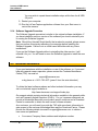
2.4 Using LuCam Capture
The LuCam Capture application is a simple demonstration program, that is easy
to use. The application is built using the SDK and provides an example of what
the API can do; however, it does not incorporate all of the available features of
the API. The complete source code for this application is available to those that
purchased the SDK.
Only one camera may be controlled by each instance of LuCam Capture, but
several instances of the application may be run simultaneously. If more than one
camera is detected by the application, a list of available camera serial numbers is
presented, allowing the user to select the camera they wish to control.
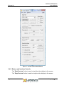
2.4.1 Menu Items
“Preview Frame Rate…” will display the average frame rate of the preview
window. The average is computed over the whole time span that the display has
been actively previewing since the last time Start Preview was pressed.
“Show Image Stats…” will display a window showing the average image
intensity for both the preview and snapshots. It takes into consideration the
current pixel depth. It also shows the average color pixel value in each mode.
When the “Update for …” options are selected, the average values are updated
with each new image received. Deselecting these options disables the updates.
“Move Capture Window to Origin” will move the capture window to the top left
corner of your desktop.
“Read/Write Registers…” will pop up a dialog allowing you to read and write
the registers of the camera. This is an advanced function and should not be
used without the advice of our technical support staff.
“Light Source” provides the option of selecting the ambient lighting source that
is being used so that the proper colour correction can be performed by the
camera. The visual impact resulting from the light source adjustment varies by
camera model, and in some cameras the impact is negligible.
“Enable Preview 16-bit Mode” will put the camera into 16-bit video preview
mode. The video preview window will only display the upper 8 bits but when you
hit the Capture button will capture 16-bit video frames. (The number of actual
valid data bits per pixel will vary by camera model. Refer to the camera
datasheet for the output options available for a specific model.)
“Monochrome Preview” puts the camera into monochrome mode.
Page 7
Copyright © 2008
Lumenera USB Camera
User’s Manual
Release 5.0
“Sharpen Captured Image” applies a sharpening algorithm to the image when
it’s captured (not in the live preview). If an image is currently being displayed,
this option will toggle the displayed image between sharpened and unsharpened.
“Image Averaging” averages 5 frames of video together to reduce random
image noise, when the Capture button is pressed. This option will produce
undesireable results when the field of view contains objects in motion.
“Image Summing” sums 5 frames of video together to produce a brighter
image, when the Capture button is pressed. This option will produce
undesireable results when the field of view contains objects in motion. The
resulting image will be 5 times brighter than the current preview images.
“Hue/Saturation…” pops up a dialog that allows you to adjust the hue and
saturation of the live preview.
“Display Video Properties…” pops up a “canned” dialog generated by the
LuCam API that allows you to adjust video properties (Exposure, Gain, Gamma,
Brigtness, Contrast).
Copyright © 2008
Page 8
Lumenera USB Camera
User’s Manual
Release 5.0
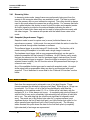
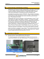
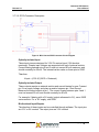
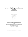
Figure 1 - LuCam Capture Main Window
2.4.2 Buttons and Interface Controls
The “Start Preview” button is used to start the video display to the screen.
The “Stop Preview” button is used to stop the video display to the screen.
Page 9
Copyright © 2008
Lumenera USB Camera
User’s Manual
Release 5.0
Video Frame Capture
The “Capture” button is used to grab a frame of video from the video stream and
display it on screen.
The “Save As…” button is used to save the image to disk in one of the available
formats.
The “Hide View” button will close the image display window.
The “Capture & Save Bayer Data” toggle button allows you to view and save the
raw Bayer data that comes from the camera, before it is processed into 24-bit
RGB data. (Color cameras only.) If a captured image is currently being
displayed, this button will toggle the image between raw Bayer and processed
24-bit data.
Video Image Control
The “Image Size” dropdown list provides the available video display resolutions.
The “Frame Rate” toggle buttons provide the selection of the available display
frame rates. Not all cameras have this capability.
The “Exposure” slider is used to adjust the video exposure time in milliseconds.
The “AEC” toggle button is used to toggle the Automatic Exposure Control (not
available for all cameras). When selected, the slider changes to “Luminance
Target” allowing you to select the average brightness that you want to maintain
as ambient lighting changes. The exposure will be automatically adjusted in an
attempt to maintain the average brightness.
The “Gain” slider is used to adjust the global gain of the camera for both video
mode and when using the Snapshot mode (described below). The gain value is
a multiplicative factor, so a value of 1 means no gain. The value of every pixel in
the image is multiplied by the gain value, resulting in an increase in image
brightness. When the gain setting is increased, any sensor noise will be
amplified, along with the image data, and the picture quality will be degraded.
The higher the gain, the more noticeable this is.
The “AGC” toggle button is used to toggle the Automatic Gain Control (not
available for all cameras). When selected, the slider changes to “Luminance
Target” allowing you to select the average scene brightness that you want to
maintain as ambient lighting changes. The gain will be automatically adjusted in
an attempt to maintain the average brightness.
Note: When both AEC and AGC are selected, if an increase in
brightness is required, exposure is adjusted up first until its limit is
reached and then gain is adjusted. When a decrease in brightness
is required, gain is adjusted down first until its limit is reached and
then exposure is adjusted. This maintains the best image quality.
Copyright © 2008
Page 10
Release 5.0
Lumenera USB Camera
User’s Manual
The “Gamma” value is applied to the image to make it look better on screen. It is
used to correct the non-linearity inherent in most CRT monitors. A value of 1
represents no gamma correction. Values less than one will make the image
appear darker while a value greater than one will make the image appear
brighter. For more information about Gamma and why it’s used, consult the
following reference: www.poynton.com/GammaFAQ.html
The “WB” button adjusts a camera’s color gain settings (white balance) of the
video preview, based on the overall image, using the gray world algorithm. It is
done in software by grabbing a video frame, analyzing it, adjusting the color
gains and repeating, until the colors in the image are balanced. That is, there is
an equal amount of Red, Blue and Green in the image. It is best to put a neutral
target (e.g. white or grey paper) in front of the camera before performing a color
balance. For best results, the image exposure time should be adjusted so that
the scene does not contain any saturated pixels (values at maximum brightness).
Snapshot Settings
The “Exposure” value controls the time between the start of image capture and
the data read-out for a snapshot, expressed in milliseconds.
The “Exposure Delay” value indicates the time in milliseconds between the
receiving the snapshot trigger input and the start of integration on the sensor.
The “Snapshot” button is used to grab an image from the camera using its
snapshot mode and half-global or global shutter (if available), and display it on
screen. (see Shutter Types and Camera Modes sections below for more
information about snapshot mode and global shutter)
The “Hide View” button will close the snapshot image display window.
The “Wait for HW Input Trigger” toggle is used to specify that the snapshot
should be hardware triggered using the HW trigger input of the camera’s external
header. With this option selected, when the “Snapshot” button is pressed, the
software will pause as the camera waits for the hardware trigger before returning
the image. There is a built-in time-out of 25 seconds after which time if the
hardware trigger has not occurred, the software will resume operation.
The “Use Strobe Trigger” toggle is used to specify that during the snapshot
exposure, the strobe trigger output should be fired.
The “Strobe Delay” value indicates the time in milliseconds between the rising
edge of strobe output and the rising edge of the strobe trigger pulse.
The “Save As…” button is used to save the snapshot image to disk in one of the
available formats.
The “16 Bits per Pixel” toggles the camera between 8 and 16-bit data mode for
snapshot capture.
Page 11
Copyright © 2008
Lumenera USB Camera
User’s Manual
Release 5.0
The “White Balance Gains for Strobe Snapshot” values allow you to set the
Red, Green and Blue gains to be used during the snapshot capture. This allows
you to white balance according to the strobe lighting that is being used. They are
only applied if the “Use Strobe Trigger” option is selected.
Copyright © 2008
Page 12
Release 5.0
Lumenera USB Camera
User’s Manual
3
Understanding Your Camera
3.1 Shutter Types
Depending on which camera model you have, the following electronic shutter
types may or may not be present. Check the table at the end of this section to
determine which camera model has which shutter type. These types are
selectable for the snapshot mode of the camera (described in a later section).
3.1.1 Rolling Shutter
With a rolling shutter the exposure process begins, whereby, rows of pixels in the
image sensor start exposing in sequence, starting at the top of the image and
proceeding row by row down to the bottom. At some later point in time, the
readout process begins, whereby, rows of pixels are read out in sequence,
starting at the top of the image and proceeding row by row down to the bottom in
exactly the same manner and at the same speed as the exposure process.
The time delay between a row starting to expose and a row being read out is the
integration time, also known as the exposure time. This integration time can be
varied from a single line (start exposure followed by a read out while the next line
is exposing) up to a full frame time (last line starts exposing at the bottom of the
image before reading starts at the top). In some cases, longer exposures can be
obtained by delaying the read out even longer (during which time, the entire array
is exposing).
Since the integration process moves through the image over some length of time,
skewing of moving objects may become apparent. For example, if a vehicle is
moving through the image during capture, light from the top of the vehicle will be
integrated at some earlier time than light from the bottom of the vehicle, causing
the bottom of the vehicle to appear slanted forward in the direction of motion.
For most slow moving objects or still image capture, this motion artifact is not
noticeable.
3.1.2 Half Global Shutter
With a half global shutter, the entire image array starts exposing at the same time
(globally). At some later point in time, the readout process begins, whereby;
Page 13
Copyright © 2008
Lumenera USB Camera
User’s Manual
Release 5.0
rows of pixels are read out in sequence, starting at the top of the image and
proceeding row by row down to the bottom (exactly like the rolling shutter case).
The time between the global start of integration and the start of readout is
defined as the exposure time. However, since during readout of the image, the
lines are still integrating (like rolling shutter), the actual image exposure differs
from the top to the bottom. The difference is the time taken to readout the image
and varies for each camera (70 ms is typical). Under bright ambient lighting
conditions, the image will appear brighter; the further down the image you go. A
half-global shutter is most effective when used under controlled lighting (eg.
strobe flash).
Because integration continues to occur during readout, the skewing motion
artifact can still occur.
3.1.3 Global Shutter
With a global shutter, the entire image array starts exposing at the same time
(globally). At some later point in time, the entire image array stops exposing at
the same time and the image is read out in sequence, starting at the top of the
image and proceeding row by row down to the bottom (sometimes odd rows are
read out first followed by the even rows). The difference from the other modes is
that during readout, the imager is no longer integrating light.
The time delay between the start of exposure and end of exposure is defined as
the exposure time and it represents the total amount of time that the image
integrates.
Because all the pixels start exposure at the same time, integrate over the same
interval, and stop exposing at the same time, there is no potential for motion
artifacts as there is in the other modes.
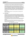
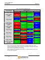
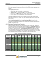
Table 1 - Shutter Types by Camera Model
Camera Model
Lu050, Lu055
Lu070, Lu075,
Lw070, Lw075,
Lm075
Lu080, Lu085,
Lm085
Lu100, Lu105
Lu110, Lu115
Lu120, Lu125
Lu130, Lu135,
Lw130, Lw135,
Lm135
Copyright © 2008
Rolling Shutter
Half Global Shutter
Global Shutter
Yes
No
Yes
No
No
Yes
No
No
Yes
Yes
Yes
Yes
Yes
No
No
No
No
Yes
No
No
Yes
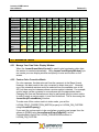
Page 14
Lumenera USB Camera
User’s Manual
Release 5.0
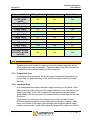
Camera Model
Lu160, Lu165,
Lw160, Lw165,
Lm165
Lu170, Lu175
Lu200, Lu205
Lw230, Lw235
Lu270, Lu275
Lw290, Lw295
Lu330, Lu335
Lu370, Lu375
Lw560, Lw565
Lw570, Lw575
Lw620, Lw625
Lw11050, Lw11056,
Lw11057, Lw11058,
Lw11059
Rolling Shutter
Half Global Shutter
Global Shutter
No
No
Yes
Yes
Yes
No
Yes
Yes
No
Yes
No
Yes
Yes
No
Yes
No
No
No
No
No
No
Yes
Yes
No
No
Yes
No
No
Yes
No
Yes
No
No
No
No
Yes
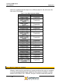
3.2 Scanning Mode
Depending on which model of camera you have, the frame integration will be
either progressive scan or interlaced. Check the table at the end of this section
to determine which camera model has which scan type.
3.2.1 Progressive Scan
In a progressive scan camera, the entire image is integrated (exposed) at one
point in time (for global shutters) or line-by-line from top to bottom (for rolling
shutters).
3.2.2 Interlaced Scan
In an interlaced scan camera, the entire image is made up of two fields. Each
field is made up of the odd lines of the image (odd field) or the even lines of the
image (even field). Each field is captured in a progressive manner (using a
global shutter), but the exposure for the second field is started after the first one
is read out.
When there is no movement of the object being viewed, you will not see a
difference between progressive and interlaced scan images. However, when
there is movement of the object, the interlaced scan image will exhibit image
artefacts known as the “comb” effect where the edges of the object look like the
Page 15
Copyright © 2008
Lumenera USB Camera
User’s Manual
Release 5.0
teeth of a comb because the object is in a different place for the odd versus the
even rows of the image.
Table 2 - Scan Mode by Camera Model
Camera Model
Scan Mode
Lu050, Lu055
Lu070, Lu075,
Lw070, Lw075,
Lm075
Lu080, Lu085,
Lm085
Lu100, Lu105
Lu110, Lu115
Lu120, Lu125
Lu130, Lu135,
Lw130, Lw135,
Lm135
Lu160, Lu165,
Lw160, Lw165,
Lm165
Lu170, Lu175
Lu200, Lu205
Lw230, Lw235
Lu270, Lu275
Lw290, Lw295
Lu330, Lu335
Lu370, Lu375
Lw560, Lw565
Lw570, Lw575
Lw620, Lw625
Lw11050, Lw11056,
Lw11057, Lw11058,
Lw11059
Progressive
Progressive
Progressive
Progressive
Progressive
Progressive
Progressive
Progressive
Progressive
Progressive
Progressive
Progressive
Progressive
Interlaced
Progressive
Interlaced
Progressive
Progressive
Progressive
3.3 Use of Flash or Strobe
A flash or strobe may be used with any camera model and the option is available
to provide a programmable trigger signal from the camera to the flash or strobe
device to tell it when to fire. However, the type of shutter mode being used will
Copyright © 2008
Page 16
Release 5.0
Lumenera USB Camera
User’s Manual
dictate what conditions will be required and how well flash photography will work
with the camera.
3.3.1 Flash with Rolling Shutter
The use of a flash with rolling shutter is only feasible for cameras that allow
exposures longer than frame read out time (typically about 70 ms). This is
because with exposures less than that, only a band across the imager is being
exposed at the same point in time and when the flash occurs, it will only
illuminate that region of the imager. The flash must be fired at the time when all
the pixels of the imager are simultaneously sensitive to light. The strobe signal
from the camera is generated at a user selectable delay from that point in time.
Generally, the ambient lighting should be low enough (i.e. dark) so that during
the overall exposure the ambient light will not contribute much to the overall
brightness of the image. This is particularly true if the flash is being used to “stop
the motion” of a fast-moving object, otherwise, blurring or skewing may occur.
For imaging still objects, this is not as much of a concern. In this case, you only
need to ensure that you are not overexposing the object with both a long
exposure and a flash.
3.3.2 Flash with Half Global Shutter
The use of a flash or strobe with an imager using a half global shutter is similar to
the rolling shutter case. However, because the imager starts at once exposing
all the pixels globally, the strobe signal from the camera is generated at a user
selectable delay from the start of exposure. It doesn’t have to first wait for the
rolling shutter to “open up” all the way, like for rolling shutter mode.
Again, the ambient lighting should be low enough so that during the image read
out where the imager is still sensitive, the ambient light will not contribute much
to the overall brightness of the image. This is a concern for both moving objects
where both blurring and skewing may occur, and still objects where you may
have uneven brightness from the top of the image to the bottom (as described in
the previous section.)
3.3.3 Flash with Global Shutter
The use of a flash or strobe with a global shutter has no limitations or concerns.
The strobe signal from the camera is generated at a user selectable delay from
the start of the exposure. Very short, global exposures can be used, so, there
will be no blurring or skewing or overexposure due to long exposures.
3.4 Camera Modes
The camera has two operating modes: Streaming Video, and Snapshot.
Page 17
Copyright © 2008
Lumenera USB Camera
User’s Manual
Release 5.0
3.4.1 Streaming Video
In streaming video mode, image frames are continuously being sent from the
camera to the computer where they are available for use. The data is pushed
from the camera, with no user intervention required. The rolling shutter is always
used in this mode where the camera has a rolling shutter. For cameras that have
only a global shutter, this shutter is used for both the video and snapshot modes.
An output signal is provided on the external header indicating the start of
exposure for each video frame and can be used to help synchronize events with
the video images. The camera will operate with the fastest frame rates in this
mode.
3.4.2 Snapshot (Asynchronous Trigger)
Snapshot mode is used to capture one (or more) individual frames in an
asynchronous manner. In this mode, the user must initiate the action to start the
image retrieval through either hardware or software.
The software trigger is provided using API function calls. The function call is
made causing the snapshot to be taken and a single image is returned.
The hardware input trigger (with a user programmable delay) can be used to
initiate the snapshot via the external I/O interface. An API function call is made
that puts the camera into this “wait for hardware trigger” state and then “blocks”
until the hardware trigger is received. Once the trigger is received (or the user
selected timeout occurs), the API function returns and passes back the image (or
a timeout error code).
Any of the available shutter types can be used with snapshot mode. An output
strobe signal with programmable delay can also be synchronized with each
snapshot. This is described in more detail in the “External I/O Interface” section
below.
3.5 Data Format
Data from the camera can be retrieved in one of two pixel formats. These
formats represent the bit depth in bits per pixel [bpp]. Either 8 bpp or 16 bpp can
be selected. For 16 bpp, not all of the bits are necessarily valid data bits.
Depending on the camera model, 10, 12 or 14 bits will be valid data, with the
remaining 6, 4, or 2 bits always set to zero. A completely dark pixel will have all
valid bits set to zero and a completely light-saturated pixel will have all valid bits
set to one. The valid data bits are stored most significant bit aligned in each
word. The words are in Big Endian byte order for Lu series cameras (most
significant byte is the first of each byte pair), and Little Endian byte order for Lw
series camera (least significant byte is first of each byte pair). The following
tables illustrate this point where the data for the first three pixels (completely
light-saturated) of an image are represented.
Copyright © 2008
Page 18
Lumenera USB Camera
User’s Manual
Release 5.0
Table 3 - Pixel Data Format for 16 bpp (10 valid data bits) for all Lu series cameras
Pixel
16-bit Word
Byte Order
Binary value
Hex value
Decimal value
Pixel 1
Pixel 2
Pixel 3
Word 1
Word 2
Word 3
Byte 1
Byte 2
Byte 3
Byte 4
Byte 5
Byte 6
LSB
MSB
LSB
MSB
LSB
MSB
11000000 11111111 11000000 11111111 11000000 11111111
0xC0
0xFF
0xC0
0xFF
0xC0
0xFF
192
255
192
255
192
255
Table 4 - Pixel Data Format for 16 bpp (10 valid data bits) for all Lw series cameras
Pixel
16-bit Word
Byte Order
Binary value
Hex value
Decimal value
Pixel 1
Pixel 2
Pixel 3
Word 1
Word 2
Word 3
Byte 1
Byte 2
Byte 3
Byte 4
Byte 5
Byte 6
MSB
LSB
MSB
LSB
MSB
LSB
11111111 11000000 11111111 11000000 11111111 11000000
0xFF
0xC0
0xFF
0xC0
0xFF
0xC0
255
192
255
192
255
192
For monochrome cameras, each byte (8bpp) or word (16bpp) represents one
complete pixel in the image.
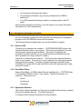
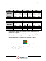
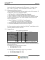
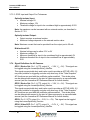
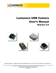
For color cameras, the data arrives from the camera in the raw Bayer format.
The imager in a color camera is a monochrome imager that has a Red, Green or
Blue color filter over each pixel. The arrangement of this color filter mosaic is
called the Bayer format. An example of this can be seen in Figure 1.
Figure 2 - Example of a 6x6 Pixel Area of Color Imager Mosaic Pattern
Each byte (8bpp) or word (16bpp) will be one of the three mosaic colors: Red,
Green or Blue. The order of these colors is camera model dependent and can
be found in the following Table.
Page 19
Copyright © 2008
Lumenera USB Camera
User’s Manual
Release 5.0
Table 5 - Bayer Data Color Mosaic Order
Camera Model
Lu050, Lu055
Lu070, Lu075,
Lw070, Lw075,
Lm075
Lu080, Lu085
Lm085
Lu100, Lu105
Lu110, Lu115
Lu120, Lu125
Lu130, Lu135,
Lw130, Lw135,
Lm135
Lu160, Lu165,
Lw160, Lw165,
Lm165
Lu170, Lu175
Lu200, Lu205
Lw230, Lw235
Lu270, Lu275
Lw290, Lw295
Lu330, Lu335
Lu370, Lu375
Lw560, Lw565
Lw570, Lw575
Lw620, Lw625
Lw11050, Lw11056,
Lw11057, Lw11058,
Lw11059
Pixel 1 Row 1
Red
Mosaic Order
Pixel 2 Row 1 Pixel 1 Row 2
Green 1
Green 2
Pixel 2 Row 2
Blue
Red
Green 1
Green 1
Blue
Green 1
Blue
Blue
Green 1
Green 1
Red
Green 1
Green 1
Red
Blue
Blue
Green 2
Green 2
Blue
Red
Green 2
Red
Red
Green 2
Green 2
Red
Green 1
Green 2
Blue
Red
Green 1
Green 2
Blue
Green 1
Blue
Red
Green 1
Green 1
Red
Green 1
Red
Green 1
Green 1
Red
Green 1
Green 1
Red
Blue
Green 1
Red
Green 1
Red
Red
Blue
Green 2
Green 2
Blue
Red
Green 2
Blue
Green 2
Blue
Blue
Green 2
Red
Blue
Green 2
Green 2
Blue
Green 2
Blue
Green 2
Green 2
Green 1
Red
Blue
Green 2
When using the LuCam Capture application to preview video from a color
camera or save images to disk, conversion of the data to standard 24-bit RGB
data is done by the software automatically.
When using the API (available with the SDK), you have complete control over
this conversion process.
Copyright © 2008
Page 20
Lumenera USB Camera
User’s Manual
Release 5.0
3.6 Subwindowing, Subsampling & Binning
Subwindowing, also known as region of interest (ROI), is the ability of the camera
to output a smaller image size (subwindow) than the whole imager array. An
imager that supports a maximum resolution of 1280x1024 pixels for example,
could output a subwindow of 640x480 pixels with the subwindow being
positioned nearly anywhere inside the 1280x1024. The subwindow is actually a
smaller field of view than the maximum resolution available. There are limitations
on the granularity of the subwindow size and on its position within the whole
array. The granularity is 8 pixels.
Subsampling, also known as decimation, is the throwing away of every nth pixel
or pixel pair in the image in the X and/or Y directions. For example, an imager
with a maximum resolution of 1280x1024 could throw away every second pixel in
both the X and Y directions and output an image that is 640x512 pixels, yet
covers the same field of view of the original full resolution. Not all cameras
support Subsampling. Those that do may support subsample levels of 2, 4 or 8.
Some cameras even allow different Subsampling in the X vs. the Y directions.
Binning is similar to Subsampling, except instead of throwing pixels away, pixel
values are combined in some fashion. They can be either summed (to provide
greater sensitivity) or averaged (to reduce noise). The resulting resolution would
be the same as for Subsampling, but the data from every pixel is used. Several
cameras support Binning with binning levels up to 8 by 8.
3.7 External I/O Interface
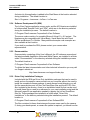
3.7.1 Standard LuCam Camera GPIO Interface Description
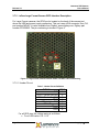
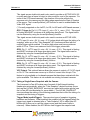
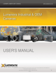
For board-level cameras, the External Interface Header can be found in the
corner of the PCB next to the silver USB connector. For enclosed cameras, it is
Figure 3 - External Header Location and Pin Numbering
Page 21
Copyright © 2008
Lumenera USB Camera
User’s Manual
Release 5.0
found on the side of the camera near the USB connector. It is a male, 2 mm
pitch, 16-pin (2 x 8) header. The pin numbering can be seen in Figure 2.
3.7.1.1 Recommended Mating Connectors
The following mating connectors have been tested to work with the cameras. All
of them are for 16-pin (2 x 8), 2mm pitch headers.
• AMP/Tyco P/N 2-111623-3 IDC Ribbon Cable Receptacle
• Molex GC/Waldom P/N 87568-1663 IDC Ribbon Cable Receptacle
• Molex GC/Waldom P/N 87568-1693 IDC Ribbon Cable Receptacle Locking
For above mating connectors, 1mm, 28AWG stranded, round conductor flat
cable is recommended.
•
•
•
Molex GC/Waldom 51110-1650 Wire Crimp Receptacle
o Female Crimp Terminal for above – P/N 50394-8100
Norcomp P/N 2564-16-01RP2 Vertical Dual Row Receptacle
Sullins P/N PPWN082AFCN Vertical Dual Row Receptacle
All of these connectors can be purchased from Digi-Key® (www.digikey.com) but
other parts suppliers may also carry them.
3.7.1.2 Header Pin-out
Table 6 - Header Pin-out Definition
SIGNAL
GPO1 / Strobe Out (AL)
GPO2 / Strobe Out (AH)
GPO3
GPO4 / Video SOF
GPI1 / Trigger In
GPI2
GPI3
GPI4
PIN #
1
3
5
7
9
11
13
15
PIN #
2
4
6
8
10
12
14
16
SIGNAL
GND
GND
GND
GND
GND
GND
GND
GND or VCC Output (opt.)*
None of the signals can supply much current. Maximum current draw should be
kept to less than 24 mA.
For all GPO pins, the voltage swing is as follows:
• For a LOW value: 0.0 - 0.1V
• For a HIGH value: 3.0 - 3.3V
For all GPI pins, the tolerated input voltage swing is as follows:
• For LOW input voltages: 0.0 - 0.5V
• For HIGH input voltages: 2.0 - 5.0V
Copyright © 2008
Page 22
Lumenera USB Camera
User’s Manual
Release 5.0
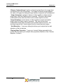
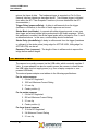
3.7.2 LuCam Large Format Camera GPIO Interface Description
For Large Format cameras, the GPIO port is located on the back of the camera just
above the USB and power supply connectors. This port uses a DIN connector from CUI,
part number MD-80. It is also available from Digikey, www.digikey.com, Digikey part
number CP2090ND. The pin numbering is shown in Figure 4.
4
Figure 4 - Large Format Camera External Header Location and Pin Numbering
3.7.2.1 Header Pin-out
Table 7 - Header Pin-out Definition
SIGNAL
GND
GPO1 / Strobe Out (AL)
GPO2 / Strobe Out (AH)
GPO3
GPO4 / Video SOF
GPI1 / Trigger In
GPI2
GPI3
PIN #
1
2
3
4
5
6
7
8
For all GPO pins, the voltage swing is as follows:
• For a LOW value: 0.0 - 0.1V
Page 23
Copyright © 2008
Lumenera USB Camera
User’s Manual
•
Release 5.0
For a HIGH value: 3.0 - 3.3V
For all GPI pins, the tolerated input voltage swing is as follows:
• For LOW input voltages: 0.0 - 0.5V
• For HIGH input voltages: 2.0 - 5.0V
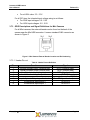
3.7.3 GPIO Descriptions and Signal Definitions for Mini Cameras
For all Mini cameras, the external header can be found on the back of the
camera near the Mini USB connector. It uses a standard RJ45 connector as
shown in Figure 5.
Figure 5 - Mini Camera External Header Location and Pin Numbering
3.7.3.1 Header Pin-out
Table 8 - Header Pin-out Definition
Pin
1
2
3
4
5
6
7
8
Function
optically-isolated output, negative lead
optically-isolated output, positive lead
optically-isolated input, negative lead
bi-directional input/output 0
ground
optically-isolated input, positive lead
bi-directional input/output 2
bi-directional input/output 1
Copyright © 2008
Signal
GPO1 (negative lead)
GPO1 (positive lead)
GPI1 (negative lead)
GPO/GPI2
ground reference for GPIO2-4
GPI1 (positive lead)
GPO/GPI4
GPO/GPI3
Page 24
Lumenera USB Camera
User’s Manual
Release 5.0
3.7.3.2 GPIO Connector Description
Figure 6 - Mini Camera GPIO Connector Circuit Diagram
Optically-Isolated Input
These input pins are designed for 3.3V-5V nominal input (12V absolute
maximum). Greater input voltages are supported with use of external resistor.
Current flowing between pins 6 and 3 must not exceed 50 mA maximum, and
should nominally be 20 mA. The internal resistor value on these pins is 220Ω.
Therefore,
Vinput = (0.02 A)*(220 Ω + Rexternal)
Optically-Isolated Output
These outputs require an external resistor and current biasing for use. Connect
pin 2 to a supply voltage, and place a resistor between pin 1 and Ground.
Measure the current output at pin 1. The current flowing between pins 2 and 1
must not exceed 50 mA, and should nominally be 20 mA.
For example, if biasing with a 5V supply (output referenced to 5V), use a 220Ω
series resistor. For a 12V supply, use 560Ω.
Bi-directional Input/Outputs
The direction of these inputs can be controlled through software. The input pins
are 3.3V or 5V nominal. The output pins are 3.3V nominal.
Page 25
Copyright © 2008
Lumenera USB Camera
User’s Manual
Release 5.0
3.7.3.3 GPIO Input and Output Port Tolerances
Optically-isolated Input:
• Nominal voltage: 5V
• Maximum voltage: 12V
• Threshold voltage for input to be considered high is approximately 0.55V
Note: the maximum can be increased with an external resistor, as described in
Section 3.7.3.2.
Optically-isolated Output:
• Output requires an external resistor
• Maximum voltage depends on the external resistor value
Note: Maximum current that can be provided from the output port is 50 mA.
Bi-directional I/O:
• Nominal voltage can be either 3.3V or 5V
• Maximum voltage: 5V
• Minimum threshold for input to be considered high is approximately 2V
• Maximum threshold for an input to be considered low is approximately
0.8V
3.7.4 Signal Definitions for All Cameras
GPO1 / Strobe Out: Pin 1, LVTTL output (Voh ~ 3.0V, Vol ~ 0V). This signal can
be toggled using the LucamGpioWrite() function.
This signal serves double duty and is also used to provide an ACTIVE LOW, 5.5
ms pulse (suitable for triggering a strobe unit) when any of the “Take Snapshot”
API functions are used with the useStrobe option enabled. This strobe pulse
can be delayed with respect to the start of frame exposure by a user selectable
amount (see the Lumenera API Reference Manual for further details).
GPO2 / Strobe Out: Pin 3, LVTTL output (Voh ~ 3.0V, Vol ~ 0V). This signal can
be toggled using the LucamGpioWrite() function.
This signal serves double duty and is also used to provide an ACTIVE HIGH, 5.5
ms pulse (suitable for triggering a strobe unit) when any of the “Take Snapshot”
API functions are used with the useStrobe option enabled. This strobe pulse
can be delayed with respect to the start of frame exposure by a user selectable
amount (see the Lumenera API Reference Manual for further details).
GPO3: Pin 5, LVTTL output (Voh ~ 3.0V, Vol ~ 0V). This signal can be toggled
using the LucamGpioWrite() function.
GPO4 / Video SOF: Pin 7, LVTTL output (Voh ~ 3.0V, Vol ~ 0V). This signal can
be toggled using the LucamGpioWrite() function.
Copyright © 2008
Page 26
Release 5.0
Lumenera USB Camera
User’s Manual
This signal serves double duty and is also used to provide an ACTIVE HIGH, 85
us pulse each time a frame is output in video mode for most of the cameras. For
some of the CCD based cameras*, the duration of the pulse reflects the
exposure set in the camera and the falling edge represents the Start of Readout
of the sensor. The LucamGpoSelect() API function is used to enable/disable the
Video SOF signal.
(* Currently supported on the Lw070, Lw130, Lw160 and Lw230 based cameras.)
GPI1 / Trigger In: Pin 9, LVTTL input (Vin min = 0V, Vin max = 3.3V). This signal
is floating and MUST be driven at all times when being used. The signal status
can be obtained by using the LucamGpioRead() function.
This signal serves double duty and is also used to receive an ACTIVE HIGH,
LVTTL input (Vin min = 0V, Vin max = 3.3V) pulse which will trigger the taking of a
snapshot, when any of the “Take Snapshot” API functions are used with the
useHwTrigger option enabled. The active high pulse must have a minimum
width of 0.5 us. There is no maximum limit to the trigger pulse width.
GPI2: Pin 11, LVTTL input (Vin min = 0V, Vin max = 3.3V). This signal is floating
and MUST be driven at all times when being used. The signal status can be
obtained by using the LucamGpioRead()function.
GPI3: Pin 13, LVTTL input (Vin min = 0V, Vin max = 3.3V). This signal is floating
and MUST be driven at all times when being used. The signal status can be
obtained by using the LucamGpioRead() function.
GPI4: Pin 15, LVTTL input (Vin min = 0V, Vin max = 3.3V). This signal is floating
and MUST be driven at all times when being used. The signal status can be
obtained by using the LucamGpioRead() function.
VCC Output: This optional feature allows the camera to output a 3.3 V DC signal
on Pin 16. The camera can source up to 50mA of current from this pin. This
feature is only available on Lw-based cameras that have been ordered with this
option available. This feature is not available on existing Lu-based cameras.
3.7.5 Taking a Single-Frame Snapshot with the Camera
The Lumenera LuCam API makes use of several of the External Interface
Header pins automatically, when the “Take Snapshot” related functions (those
that use the LUCAM_SNAPSHOT structure) are called with certain options (see
the LuCam API documentation for more details.) The LUCAM_SNAPSHOT
structure allows the setting of the following parameters that control the taking of a
snapshot and the timing of triggers:
Trigger Mode (useHwTrigger): There are two types of snapshot triggering,
hardware and software. When enabled, the snapshot will be triggered when the
trigger input signal is detected after a “Take Snapshot” API is called (the API
blocks until it times out or until the trigger occurs and the frame of data is
returned). When disabled, the API function itself triggers the snapshot and
Page 27
Copyright © 2008
Lumenera USB Camera
User’s Manual
Release 5.0
returns the frame of data. The hardware trigger is expected on Pin 9 of the
External Interface Header as described above. The software trigger is initiated
from within the API “Take Snapshot” functions (for more details see the API
documentation.)
Trigger Delay (exposureDelay): A delay in milliseconds from the trigger
(hardware or software) to the start of frame exposure can be set.
Strobe Mode (useStrobe): In concert with either triggering mode, a user may
also trigger an external strobe light synchronized to the frame exposure. When
this parameter is enabled, the strobe signal pulse will be initiated on Pins 1 and 3
as described above. In this case, a strobe delay should be defined.
Strobe Delay (strobeDelay): A delay in milliseconds from the trigger (hardware
or software) to the strobe pulse (rising edge for ACTIVE HIGH, falling edge for
ACTIVE LOW) can be set.
Exposure Time (exposure): The length of time in milliseconds to expose the
image before readout begins.
3.8 External Power
The camera is normally powered via the USB cable, which nominally supplies 5
Volts. A power adapter can also be used to power the camera, in cases where
the USB cable does not supply power (e.g. from a Laptop computer or nonpowered USB hub.)
The external power adapter must adhere to the following specifications:
For Lu series cameras
1. 6 Volts DC Regulated
2. 1000 mA Minimum Current Rating
3. 2.1 mm tip
4. Center positive (+)
For Lw series cameras
1. 5 Volts DC Regulated
2. 500 mA Minimum Current Rating
3. 2.1 mm tip
4. Center positive (+)
For large format cameras
1. 12 Volts DC Regulated
2. 2 A Minimum Current Rating
3. 2.1 mm tip
Copyright © 2008
Page 28
Lumenera USB Camera
User’s Manual
Release 5.0
4. Center positive (+)
3.9 Lens Mount
By default, the camera is equipped with an industry standard C-Mount lens
mount. A CS-Mount may be ordered as an option.
3.10
Camera IDs
Each camera has a unique camera ID that can be accessed through the LuCam
API interface. This ID can be useful to set specific camera functions in your
software. The LuCam Capture application displays this ID in its About dialog box.
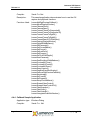
Below is a list of current camera IDs.
Camera Model
Lu050M, Lu055M (Discontinued)
Lu050C, Lu055C (Discontinued)
Lu056C (Discontinued)
Lu070M, Lu075M, Lu070C, Lu075C
Lw070M, Lw075M, Lw070C, Lw075C
Lm075M, Lm075C
Lu080M, Lu085M, Lu080C, Lu085C
Lm085M, Lm085C
Lu100M, Lu105M, Lu100C, Lu105C
Lu110M, Lu115M, Lu110C, Lu115C (Discontinued)
Lu120M, Lu125M, Lu120C, Lu125C
Lu130M, Lu135M, Lu130C, Lu135C
Lw130M, Lw135M, Lw130C, Lw135C
Lm135M, Lm135C
Lu160M, Lu165M, Lu160C, Lu165C
Lw160M, Lw165M, Lw160C, Lw165C
Lm165M, Lm165C
Lu170M, Lu175M, Lu170C, Lu175C
Lu176C
Lu200C, Lu205C
Lw230M, Lw235M, Lw230C, Lw235C
Lu270C, Lu275C
Lw290C, Lw295C
Lu330C, Lu335C
Lw330C, Lw335C
Lu370C, Lu375C
Lw570C, Lw575
Page 29
ID
0x091
0x095
0x093
0x08C
0x18C
0x28C
0x085
0x284
0x092
0x094
0x096
0x09A
0x19A
0x29A
0x08A
0x18A
0x28A
0x09E
0x082
0x097
0x180
0x08D
0x1CD
0x09B
0x19B
0x08B
0x1C5
Copyright © 2008
Lumenera USB Camera
User’s Manual
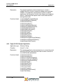
Camera Model
Lw620M, Lw625M, Lw620C, Lw625C
Lw11050C, Lw11056C, Lw11057C, Lw11058C, Lw11059C
InfinityX-21
Infinity1-1, Infinity 1
Infinity1-3, Infinity 3
Infinity1-5
Infinity1-6
Infinity 2
Infinity2-1
Infinity2-2
Infinity 4
Infinity2-3
Infinity3-1
Infinity4-4
Infinity4-11
Copyright © 2008
Release 5.0
ID
0x186
0x1C8
0x0A0
0x0A1
0x0A3
0x1Ac
0x1A6
0x0A2
0x1A2
0x1A7
0x0A4
0x1A4
0x1A5
0x1AB
0x1A8
Page 30
Lumenera USB Camera
User’s Manual
Release 5.0
4
Application Programming Interface
User’s Guide
4.1 General Overview
The LuCam API is composed of various functions that are used to control the
camera, query its state and acquire data from it. There are two groups of
functions, namely, a basic group and an advanced group.
The functions in the basic group are very simple to understand and use, and the
majority of an application’s functionality can be realized quickly using only these
functions.
The functions of the advanced group are more powerful and provide greater
flexibility and tighter control over the camera’s operation; however, they require a
more in-depth understanding of the inner workings of the camera. This
understanding can be gained from the information in the previous sections. If
you have questions that are not covered in this manual, you can e-mail our TAC
group at:
[email protected]
The following section provides guidance for performing specific and common
tasks using the LuCam API. The source code provided with the SDK contains
concrete examples of these tasks. For details and further information about
calling specific API functions, see the Lumenera USB Camera API Reference
Manual.
4.2 Basic Tasks
4.2.1 Connecting and Disconnecting
In order to communicate with a camera you must first open a connection to it and
obtain its handle. This handle is used as an input parameter to most of the other
API functions. The function used for this task is LucamCameraOpen(). When
you are completely finished with the camera, you should terminate the
connection using LucamCameraClose().
Page 31
Copyright © 2008
Lumenera USB Camera
User’s Manual
Release 5.0
Multiple cameras may be attached to the computer at one time. You can obtain
the number of cameras attached prior to connecting with any of them using the
LucamNumCameras() function. The LucamEnumCameras() function can be
used to obtain the unique serial numbers and camera type for all cameras
attached to the computer. Thus, it is possible for a specific camera to be
opened.
4.2.2 Query the Camera
Several functions exist to obtain information about the camera. To obtain the
version information for the camera, its driver and the API, you can use the
LucamQueryVersion() function.
To determine the USB connection type (e.g. USB2.0 or USB1.1) you can call
LucamQueryExternInterface().
To determine the available frame rates for the camera you can use the
LucamEnumAvailableFrameRates() function.
4.2.3 Preview Video
After a camera has been opened, a video preview can be displayed simply by
calling LucamStreamVideoControl(). This function takes three parameters; 1)
the handle to the camera, 2) a control flag (set to START_DISPLAY) and, 3) a
window handle (if NULL a window is automatically created for the video display).
More advanced applications may wish to create their own display window. The
handle to this window can be passed to the function and the video will be
previewed in it.
Pausing or stopping the preview can be achieved using the same function with
the control flag set to PAUSE_STREAM or STOP_STREAMING. When the
video stream is stopped, the display window is removed (unless you have
created your own display window.)
While video is previewing, the displayed frame rate can be obtained using the
function LucamQueryDisplayFrameRate().
4.2.4 Adjusting the Video
The API allows for the simple adjustment of several of the video properties by
providing the ability to pop up one of two pre-defined dialogs. These dialogs are
based on the DirectShow libraries. LucamDisplayPropertyPage() will pop up a
dialog for adjusting image properties (exposure, gain, etc.)
LucamDisplayVideoFormatPage() will pop up a dialog for adjusting the video
format (resolution, pixel bit depth, etc.)
Copyright © 2008
Page 32
Release 5.0
Lumenera USB Camera
User’s Manual
4.2.5 Configuring Video Format
At any time when the camera is not streaming video, you can configure the video
format using the LucamSetFormat() function. This will allow you to select the
following video properties:
1. Subwindow size
2. Subwindow position
3. Subsampling/binning mode
4. Pixel format
5. Video frame rate
There are some constraints and limitations on and associated with the above
properties.
1. The subwindow size is provided as the window width and height. Both the
width and height must be a multiple of 8.
2. The subwindow position is provided as the x and y coordinates of the top
left corner of the subwindow. Both x and y must be multiples of 8.
3. Subsampling must be the same for both x and y directions.
4. The pixel format is provided as LUCAM_PF_8 or LUCAM_PF_16 and
indicates the bit depth of the data. Using LUCAM_PF_16 doubles the
amount of data coming from the camera and will cause the maximum
frame rate to be cut in half. Although there are 16 bits per pixel in this
mode, only 10, 12, or 14 bits of data are valid (depending on the maximum
bit depth of the particular camera being used.)
5. The video frame rate provided may not be exactly as requested. The
closest smaller available rate will be provided.
4.2.6 Grab Video Data
As long as video streaming is turned on (with the LucamStreamVideoControl()
function), video data can be grabbed from the camera. The function to use for
this is LucamTakeVideo(). The number of frames must be specified as well as a
pointer to a buffer that will accept the data. The data returned from the camera is
in its raw form with each byte (for LUCAM_PF_8) or word (for LUCAM_PF_16)
returned from the camera representing a single pixel in the image. For color
cameras, the data is still in the Bayer format as described in a previous section.
It’s not necessary to be previewing the data to capture it. Grabbing video while
the preview is turned off is much more efficient and leaves the CPU free to do
other processing tasks.
Page 33
Copyright © 2008
Lumenera USB Camera
User’s Manual
Release 5.0
4.2.7 Take a Snapshot (or many)
Single snapshots can be taken using one of several functions. The
LucamTakeSnapshot() function can be used any time a camera is open to
asynchronously take a single snapshot using the camera’s snapshot mode.
Even if the camera is streaming video, the function will handle the stream,
stopping and then restarting it as necessary. The overhead associated with
managing the stream means this function is not extremely fast. However, it is a
very simple way to obtain snapshots when time is not critical.
For quicker snapshot capturing, individual functions exist to enable the snapshot
mode (LucamEnableFastFrames()), take snapshots
(LucamTakeFastFrames()) and then disable the snapshot mode
(LucamDisableFastFrames()) separately. The use of these functions helps
eliminate overhead associated with managing the streaming snapshot mode.
When the LucamEnableFastFrames() function is called, streaming is stopped,
and then snapshots can be captured repeatedly at a faster rate than with
LucamTakeSnapshot().
As with the LucamTakeVideo() functions, the data returned from the camera is
in its raw, unprocessed form.
4.2.8 Processing Images
For monochrome cameras, the data that arrives from the camera is ready for
user processing, display or capture to disk.
Data from color cameras, on the other hand, is in the raw Bayer format and will
typically need to be converted to 24-bit RGB before being user processed,
displayed or captured to disk. This conversion can be accomplished using the
LucamConvertFrameToRgb24() function.
The two additional functions LucamConvertFrameToRgb32() and
LucamConvertFrameToRgb48() are available to convert the raw Bayer data
into 32 and 48-bit RGB data respectively.
The LucamConvertBmp24ToRgb24() function will convert the byte order for
each pixel from .bmp file standard (or DIB, Device Independent Bitmap) Blue,
Green, Red (BGR) to the order Red, Green, Blue (RGB). Also the image is
flipped top to bottom so that the first row of data is found at the starting of the
buffer.
The color data can also be converted to 8-bit and 16-bit monochrome
(Greyscale) using the LucamConvertFrameToGreyscale8() and
LucamConvertFrameToGreyscale16() respectively.
4.2.9 Save Image to Disk
Saving images to disk can be accomplished with the LucamSaveImage() or
LucamSaveImageW() functions. Once a frame of data has been taken from the
camera (video or snapshot) it can be saved in one of several image formats.
Copyright © 2008
Page 34
Lumenera USB Camera
User’s Manual
Release 5.0
(For color cameras, first convert to 24-bit or 48-bit RGB to obtain a proper color
image.)
The available formats are:
1.
2.
3.
4.
Raw Data (.raw) - no header, no compression
Bitmap (.bmp) – Windows bitmap file, no compression
TIFF (.tif) – Tagged Image File Format, lossless compression
JPEG (.jpg) – JPEG compression, lossy compression
The JPEG and Bitmap formats are not capable of storing the camera output
when the camera is set to 16-bit. Only TIFF and Raw data formats support the
16-bit output.
The LucamSaveImageEx() and LucamSaveImageWEx() account for the
differences in Endianness between the Lu-based and Lw-based cameras when
saving 16-bit data to files.
4.2.10 Setting and Getting Camera Properties
Camera properties are items such as exposure, gain, contrast, etc. There are
only three functions associated with camera properties. LucamSetProperty() is
used to set the value of a camera property. LucamGetProperty() is used to get
the value of a camera property. LucamPropertyRange() will return the valid
range and default value for a given camera property. It is important to note that
not all properties are available for every camera supported by the API. The table
below indicates which properties are available for each camera model.
Table 9 – Property Availability By Camera Model
Property
Brightness
Contrast
Hue
Saturation
Sharpness
Gamma
Exposure
Gain
Red Gain
Blue Gain
Green1 Gain
Green2 Gain
Page 35
Lu050
Lu070,
Lw070,
Lm075
Lu080,
Lm085
Lu100
Lu110
Lu120
Lu130,
Lw130,
Lm130
Lu160,
Lw160,
Lm165
Lu170
Yes
Yes
Yes
Yes
No
Yes
Yes
Yes
Yes
Yes
Yes
Yes
Yes
Yes
Yes
Yes
No
Yes
Yes
Yes
Yes
Yes
Yes
Yes
Yes
Yes
Yes
Yes
No
Yes
Yes
Yes
Yes
Yes
Yes
Yes
Yes
Yes
Yes
Yes
No
Yes
Yes
Yes
Yes
Yes
No
No
Yes
Yes
Yes
Yes
No
Yes
Yes
Yes
Yes
Yes
Yes
Yes
Yes
Yes
Yes
Yes
No
Yes
Yes
Yes
Yes
Yes
Yes
Yes
Yes
Yes
Yes
Yes
No
Yes
Yes
Yes
Yes
Yes
Yes
Yes
Yes
Yes
Yes
Yes
No
Yes
Yes
Yes
Yes
Yes
Yes
Yes
Yes
Yes
Yes
Yes
No
Yes
Yes
Yes
Yes
Yes
Yes
Yes
Copyright © 2008
Lumenera USB Camera
User’s Manual
Property
Brightness
Contrast
Hue
Saturation
Sharpness
Gamma
Exposure
Gain
Red Gain
Blue Gain
Green1
Gain
Green2
Gain
Release 5.0
Lu200
Lw230
Lu270
Lw290
Lu330
Lu370
Lw560
Lw570
Lw620
Lw11050
Yes
Yes
Yes
Yes
No
Yes
Yes
Yes
Yes
Yes
Yes
Yes
Yes
Yes
No
Yes
Yes
Yes
Yes
Yes
Yes
Yes
Yes
Yes
No
Yes
Yes
Yes
Yes
Yes
Yes
Yes
Yes
Yes
No
Yes
Yes
Yes
Yes
Yes
Yes
Yes
Yes
Yes
No
Yes
Yes
Yes
Yes
Yes
Yes
Yes
Yes
Yes
No
Yes
Yes
Yes
Yes
Yes
Yes
Yes
Yes
Yes
No
Yes
Yes
Yes
Yes
Yes
Yes
Yes
Yes
Yes
No
Yes
Yes
Yes
Yes
Yes
Yes
Yes
Yes
Yes
No
Yes
Yes
Yes
Yes
Yes
Yes
Yes
Yes
Yes
No
Yes
Yes
Yes
Yes
Yes
No
Yes
Yes
Yes
Yes
Yes
Yes
Yes
Yes
Yes
No
Yes
Yes
Yes
Yes
Yes
Yes
Yes
Yes
Yes
4.3 Advanced Tasks
4.3.1 Manage Your Own Video Display Window
When the LucamStreamVideoControl() is used to start previewing video data,
the window is created automatically. Using LucamCreateDisplayWindow() you
can create your own display window and specify its size and location on the
screen.
4.3.2 Custom Color Correction Matrix
For color cameras, the data returned from the camera is in the Bayer format.
However, this data needs to be color corrected to obtain true color. Normally,
one of the standard matrices would be selected from the available ones in the
API, but there may be instances where a custom matrix is desired. For example,
a color image can be converted to monochrome with the appropriate matrix.
Changing the Hue and Saturation can also be performed using a custom matrix.
In order to apply a custom matrix, it must first be defined. This is done using the
LucamSetupCustomMatrix() function.
To make use of this custom matrix in video mode, you set the
LUCAM_PROP_CORRECTION_MATRIX property to LUCAM_CM_CUSTOM
using LucamSetProperty().
If you want the custom matrix to be used when converting raw images from the
camera to RGB24 using LucamConvertFrameToRgb24(), set the
CorrectionMatrix field of the LUCAM_CONVERSION structure to
LUCAM_CM_CUSTOM.
Copyright © 2008
Page 36
Release 5.0
Lumenera USB Camera
User’s Manual
4.3.3 Custom Look-Up-Tables (LUT)
The camera has a built-in 8-bit LUT, which is used by the Brightness, Contrast
and Gamma properties. You can provide your own customized LUT, which will
be applied to all data coming from the camera, using the
LucamSetup8bitsLUT() function. If you provide your own LUT, the Brightness,
Contrast and Gamma properties should not be used; otherwise they will
overwrite the custom LUT.
A separate LUT can be applied to individual color channels of a color camera,
using the LucamSetup8bitsColorLUT() function.
4.3.4 Video Callback functions
The Video Callback feature allows you to supply your own function that will be
called for every frame of data that arrives from the camera, giving you access to
the data stream for frame-by-frame processing. This can be used to provide a
graphic overlay, for example, or false color to a monochrome image etc.
There are two functions that can be used to register your callback. The first is
named LucamAddStreamingCallback(). The second is named
LucamAddRgbPreviewCallback(). The only difference between them is the
data format of the frame of data that is passed to them. The first function will be
passed the raw data as it comes out of the camera. The second function will be
passed the data after it has been processed into RGB data. (For monochrome
cameras, there will be no difference between the data passed for either function.)
The LucamQueryRgbPreviewPixelFormat() function can be used to determine
the bit depth of the RGB data (either 24 bpp or 32 bpp).
The callback function can be removed using either
LucamRemoveStreamingCallback() or LucamRemoveRgbPreviewCallback()
depending on which function was used to add it.
4.3.5 Snapshot Callback Functions
The Snapshot Callback feature allows you to supply your own function that will
be called for every snapshot frame that arrives from the camera, giving you
access to the snapshot stream for frame-by-frame processing. This can be used
to provide a graphic overlay, for example, or false color to a monochrome image
etc. The LucamAddSnapshotCallback() function can be used to register your
callback. The callback function can be removed by using the
LucamRemoveSnapshotCallback() function.
4.3.6 Multiple Camera, Simultaneous Image Capture
Several cameras can be connected to the same computer and used to capture
an image at the same time. This is accomplished using a set of three API
functions. LucamEnableSynchronousSnapshots() enables this mode for all
the cameras. LucamTakeSynchronousSnapshots() is used to perform the
Page 37
Copyright © 2008
Lumenera USB Camera
User’s Manual
Release 5.0
snapshot capture. LucamDisableSynchronousSnapshots() is used to disable
this mode for all the cameras.
4.3.7 Non-Volatile User Accessible Camera Memory
The camera contains a 1024-byte area of non-volatile memory that is useraccessible. The LucamPermanentBufferWrite() function can be used to write
arbitrary data to the memory area that won’t get erased when the camera is
powered down. The LucamPermanentBufferRead() function can be used to
read the memory area. There is a limit of 100,000 times that the memory area
can be overwritten reliably.
Copyright © 2008
Page 38
Lumenera USB Camera
User’s Manual
Release 5.0
4.4 SDK Sample Code Descriptions
Included in the SDK are several sample applications that demonstrate the use of
many LuCam API functions. This section describes the sample applications
provided.
If you have not purchased the SDK, compiled executables of all the sample
applications are provided “as-is” in the Sample Code directory.
4.4.1 AutoLens Sample Application
Application type: Windows Dialog
Compiler:
Visual C++.Net
Description:
This sample application demonstrates how to control the
lenses used with the Lw11059 based cameras. It provides
controls for the focus and iris of this lens.
Functions Used:
LucamAddRgbPreviewCallback()
LucamAdjustDisplayWindow()
LucamCameraClose()
LucamCameraOpen()
LucamConvertFrameToGreyscale8()
LucamConvertFrameToGreyscale16()
LucamConvertFrameToRgb24()
LucamConvertFrameToRgb48()
LucamDestroyDisplayWindow()
LucamDigitalWhiteBalance()
LucamDisableFastFrames()
LucamEnableFastFrames()
LucamGetCameraId()
LucamGetFormat()
LucamGetLastError()
LucamGetProperty()
LucamGetPropertyRange()
LucamOneShotAutoWhiteBalance()
LucamQueryVersion()
LucamRemoveRgbPreviewCallback()
LucamSaveImage()
LucamSetProperty()
LucamStreamVideoControl()
Page 39
Copyright © 2008
Lumenera USB Camera
User’s Manual
Release 5.0
4.4.2 AVISample Sample Application
Application type: Windows Dialog
Compiler:
Visual C++.Net
Description:
This sample application demonstrates how to use the AVI
capture and playback functions.
Functions Used:
LucamAddRgbPreviewCallback()
LucamAdjustDisplayWindow()
LucamCameraClose()
LucamCameraOpen()
LucamConvertFrameToGreyscale8()
LucamConvertFrameToGreyscale16()
LucamConvertFrameToRgb24()
LucamConvertFrameToRgb48()
LucamConvertRawAVIToStdVideo()
LucamDestroyDisplayWindow()
LucamDigitalWhiteBalance()
LucamDisableFastFrames()
LucamEnableFastFrames()
LucamGetCameraId()
LucamGetCurrentMatrix()
LucamGetFormat()
LucamGetLastError()
LucamGetProperty()
LucamGetPropertyRange()
LucamNumCameras()
LucamOneShotAutoWhiteBalance()
LucamPreviewAVIClose()
LucamPreviewAVIControl()
LucamPreviewAVIOpen()
LucamQueryVersion()
LucamRemoveRgbPreviewCallback()
LucamSaveImage()
LucamSetFormat()
LucamSetProperty()
LucamSetupCustomMatrix()
LucamStreamVideoControl()
LucamStreamVideoControlAVI()
LucamTakeSnapshot()
LucamTakeVideo()
LucamTakeVideoEx()
4.4.3 BlankCamera Sample Application
Application type: Windows Dialog
Copyright © 2008
Page 40
Lumenera USB Camera
User’s Manual
Release 5.0
Compiler:
Visual C++.Net
Description:
This sample application demonstrates how to use the AVI
capture and playback functions.
Functions Used:
LucamAddRgbPreviewCallback()
LucamAdjustDisplayWindow()
LucamCameraClose()
LucamCameraOpen()
LucamConvertFrameToGreyscale8()
LucamConvertFrameToGreyscale16()
LucamConvertFrameToRgb24()
LucamConvertFrameToRgb48()
LucamConvertRawAVIToStdVideo()
LucamDestroyDisplayWindow()
LucamDigitalWhiteBalance()
LucamGetCameraId()
LucamGetCurrentMatrix()
LucamGetFormat()
LucamGetLastError()
LucamGetProperty()
LucamGetTruePixelDepth()
LucamNumCameras()
LucamOneShotAutoWhiteBalance()
LucamPreviewAVIClose()
LucamPreviewAVIControl()
LucamPreviewAVIOpen()
LucamQueryVersion()
LucamRegisterEventNotification()
LucamRemoveRgbPreviewCallback()
LucamSaveImage()
LucamSetFormat()
LucamSetProperty()
LucamSetupCustomMatrix()
LucamStreamVideoControl()
LucamStreamVideoControlAVI()
LucamTakeSnapshot()
LucamTakeVideo()
LucamTakeVideoEx()
LucamUnregisterEventNotification()
4.4.4 Callback Sample Application
Application type: Windows Dialog
Compiler:
Page 41
Visual C++ .Net
Copyright © 2008
Lumenera USB Camera
User’s Manual
Release 5.0
Description:
This sample application demonstrates how to create a
callback function for both a snapshot callback and a preview
callback. The application measures the number of frames
captured by the computer for both video frames and snapshot
frames. It calculates the capture time of each frame and the
average frame rate.
Functions Used:
LucamAddRgbPreviewCallback()
LucamAddSnapshotCallback()
LucamCameraClose()
LucamCameraOpen()
LucamCreateDisplayWindow()
LucamDestroyDisplayWindow()
LucamDisableFastFrames()
LucamEnableFastFrames()
LucamGetCameraId()
LucamGetFormat()
LucamGetLastError()
LucamGetProperty()
LucamQueryVersion()
LucamRemoveRgbPreviewCallback()
LucamRemoveSnapshotCallback()
LucamStreamVideoControl()
4.4.5 CaptureToFile Sample Application
Application type: Windows Dialog
Compiler:
Visual C++.Net
Description:
This sample application demonstrates how to convert the pixel
data into ASCII text and saves this data to either a text file or
to an MS Excel® spreadsheet.
Functions Used:
LucamCameraClose()
LucamCameraOpen()
LucamConvetFrameToRgb24()
LucamConvertFrameToRgb48()
LucamDestroyDisplayWindow()
LucamGetFormat()
LucamGetLastError()
LucamGetProperty()
LucamSaveImage()
LucamSetProperty()
LucamStreamVideoControl()
LucamTakeVideo()
Copyright © 2008
Page 42
Lumenera USB Camera
User’s Manual
Release 5.0
4.4.6 ClickCrop Sample Application
Application type: Windows Dialog
Compiler:
Visual C++ .Net
Description:
This sample application demonstrates how to use the callback
function to apply an overlay to the video stream. Either a
rectangle or elliptical overlay can be selected and placed onto
the preview window. The size of the shapes can also be
defined. The position can be selected by clicking with the
mouse on a location in the preview window. A snapshot can
be taken based on the full field of view or just the overlay area.
Functions Used:
LucamAddRgbPreviewCallback()
LucamCameraClose()
LucamCameraOpen()
LucamDestroyDisplayWindow()
LucamDigitalWhiteBalance()
LucamGetFormat()
LucamGetLastError()
LucamGetProperty()
LucamOneShotAutoWhiteBalance()
LucamQueryVersion()
LucamRemoveRgbPreviewCallback()
LucamSaveImage()
LucamSetProperty()
LucamStreamVideoControl()
LucamTakeSnapshot()
4.4.7 CSharp Sample Application
Application type: Windows Dialog
Compiler:
Visual C#.Net
Description:
This sample application demonstrates how to access the
LuCamAPICOM object in a C# environment. This application
demonstrates how to preview video from the camera, take a
snapshot and save it to a file.
Functions Used:
LucamCameraClose()
LucamCameraOpen()
LucamConvetFrameToRgb24()
LucamDestroyDisplayWindow()
LucamGetFormat()
LucamGetProperty()
LucamSaveImage()
LucamSetFormat()
LucamSetProperty()
Page 43
Copyright © 2008
Lumenera USB Camera
User’s Manual
Release 5.0
LucamStreamVideoControl()
LucamTakeSnapshot()
4.4.8 DirectShow Callback Sample Application
Application type: Windows Dialog
Compiler:
Visual C++ .Net
Description:
This sample application demonstrates how to setup a callback
function using the camera’s DirectX interface. The callback
function applies a gamma function to the video data through a
LUT (Look Up Table).
Functions Used:
NA
4.4.9 DirectX Sample Application
Application type: Windows Dialog
Compiler:
Visual C++.Net
Description:
This sample application demonstrates how to access the
camera through its DirectX interface using Visual C++.Net. It
provides controls to start and stop the video stream, preview
the video data and control the demosaicing method, control
the exposure, gamma, contrast and brightness values. It also
demonstrates how to access the permanent buffer storage on
the camera.
Functions Used:
NA
4.4.10 DirectX Snapshot Sample Application
Application type: Windows Dialog
Compiler:
Visual C++ .Net
Description:
This sample application demonstrates how to acquire a
snapshot through the DirectX interface. It demonstrates how to
change the exposure and gains values, use the strobe output
and toggle the trigger input between a SW trigger and HW
trigger.
Functions Used:
NA
4.4.11 DualSlope Sample Application
Application type: Windows Dialog
Compiler:
Visual C++ .Net
Description:
This sample application demonstrates how to use the dual
slope feature of the Lu120 and Lw620 cameras.
Copyright © 2008
Page 44
Lumenera USB Camera
User’s Manual
Release 5.0
Functions Used:
LucamCameraClose()
LucamCameraOpen()
LucamConvetFrameToRgb24()
LucamConvetFrameToRgb48()
LucamDestroyDisplayWindow()
LucamGetCameraId()
LucamGetFormat()
LucamGetLastError()
LucamGetProperty()
LucamPropertyRange()
LucamQueryVersion()
LucamSaveImage()
LucamSetFormat()
LucamSetProperty()
LucamStreamVideoControl()
LucamTakeVideo()
LucamTakeSnapshot()
4.4.12 DX Control Net Sample Application
Application type: Windows Console
Compiler:
Visual C++.Net
Description:
This sample application is a console based application that
uses the DirectX interface of the camera.
Functions Used:
NA
4.4.13 EnumFrameRates Sample Application
Application type: Windows Console
Compiler:
Visual C++.Net
Description:
This sample application is a console based application that
lists the available frames rates for the camera.
Functions Used:
LucamCameraClose()
LucamCameraOpen()
LucamEnumAvailableFrameRates()
LucamGetCameraId()
LucamGetFormat()
LucamQueryVersion()
4.4.14 FastSynchSnaps Sample Application
Application type: Windows Dialog
Compiler:
Page 45
Visual C++ 6.0 and Visual C++ .Net
Copyright © 2008
Lumenera USB Camera
User’s Manual
Release 5.0
Description:
This sample application demonstrates how to do fast
synchronous snapshots from multiple cameras.
Functions Used:
LucamCameraClose()
LucamCameraOpen()
LucamConvetFrameToRgb24()
LucamDisableSynchronousSnapshots()
LucamEnableSynchronousSnapshots()
LucamGetLastError()
LucamQueryVersion()
LucamTakeSynchronousSnapshots()
LucamSaveImage()
4.4.15 Flipping Sample Application
Application type: Windows Dialog
Compiler:
Visual C++ .Net
Description:
This sample demonstrates how to flip and mirror the video
preview.
Functions Used:
LucamCameraClose()
LucamCameraOpen()
LucamDestroyDisplayWindow()
LucamGetCameraId()
LucamGetFormat()
LucamGetProperty()
LucamQueryVersion()
LucamSetFormat()
LucamSetProperty()
LucamStreamVideoControl()
4.4.16 FrameRate Sample Application
Application type: Windows Dialog
Compiler:
Visual C++ .Net
Description:
This sample demonstrates how to read the various available
frame rates.
Functions Used:
LucamCameraClose()
LucamCameraOpen()
LucamCreateDisplayWindow()
LucamDestroyDisplayWindow()
LucamGetCameraId()
LucamGetFormat()
LucamSetFormat()
LucamSetProperty()
LucamStreamVideoControl()
Copyright © 2008
Page 46
Lumenera USB Camera
User’s Manual
Release 5.0
4.4.17 Get16BitInfo Sample Application
Application type: Windows Console
Compiler:
Visual C++.Net
Description:
This sample application is a console based application that
provides information on the 16 bit mode of the camera such as
its bit depth and endianness.
Functions Used:
LucamCameraClose()
LucamCameraOpen()
LucamGetCameraId()
LucamGetFormat()
LucamGetTruePixelDepth()
LucamQueryVersion()
4.4.18 GetRanges Sample Application
Application type: Windows Dialog
Compiler:
Visual C++ .Net
Description:
This sample demonstrates how to read and write the camera
properties and get their value ranges.
Functions Used:
LucamCameraClose()
LucamCameraOpen()
LucamDestroyDisplayWindow()
LucamGetProperty()
LucamPropertyRange()
LucamSetProperty()
LucamStreamVideoControl()
4.4.19 GPI Event Signalling Sample Application
Application type: Windows Dialog
Compiler:
Visual C++ .Net
Description:
This sample application demonstrates how to link an event to
the camera’s GPI events.
Functions Used:
LucamCameraClose()
LucamCameraOpen()
LucamRegisterEventNotification()
LucamUnregisterEventNotification()
4.4.20 GpioTest Sample Application
Application type: Windows Dialog
Compiler:
Page 47
Visual C++ .Net
Copyright © 2008
Lumenera USB Camera
User’s Manual
Release 5.0
Description:
This sample application demonstrates how to read the GPI
port of the camera and write to the GPO port.
Functions Used:
LucamCameraClose()
LucamCameraOpen()
LucamCreateDisplayWindow()
LucamGetLastError()
LucamGpioRead()
LucamGpioWrite()
LucamGpoSelect()
LucamQueryVersion()
LucamStreamVideoControl()
4.4.21 Histogram Sample Application
Application type: Windows Dialog
Compiler:
Visual C++ .Net
Description:
This sample application demonstrates how to link an event to
the camera’s GPI events.
Functions Used:
LucamAddRgbPreviewCallback()
LucamAdjustDisplayWindow()
LucamCameraClose()
LucamCameraOpen()
LucamConvertFrameToRgb24()
LucamConvertFrameToRgb48()
LucamConvertRawAVIToStdVideo()
LucamDestroyDisplayWindow()
LucamDigitalWhiteBalance()
LucamGetCameraId()
LucamGetCurrentMatrix()
LucamGetFormat()
LucamGetLastError()
LucamGetProperty()
LucamGetTruePixelDepth()
LucamNumCameras()
LucamOneShotAutoWhiteBalance()
LucamQueryVersion()
LucamPreviewAVIClose()
LucamPreviewAVIControl()
LucamPreviewAVIOpen()
LucamRemoveRgbPreviewCallback()
LucamSaveImage()
LucamStreamVideoControl()
LucamStreamVideoControlAVI()
LucamSetFormat()
Copyright © 2008
Page 48
Lumenera USB Camera
User’s Manual
Release 5.0
LucamSetProperty()
LucamSetupCustomMatrix()
LucamStreamVideoControl()
LucamTakeVideo()
LucamTakeVideoEx()
4.4.22 HwTrigCount Sample Application
Application type: Windows Dialog
Compiler:
Visual C++ .Net
Description:
This sample demonstrates how to configure the camera to use
the HW trigger to capture snapshots.
Functions Used:
LucamAddSnapshotCallback()
LucamCameraClose()
LucamCameraOpen()
LucamCreateDisplayWindow()
LucamDestroyDisplayWindow()
LucamDisableFastFrames()
LucamEnableFastFrames()
LucamGetCameraId()
LucamGetFormat()
LucamQueryVersion()
LucamRemoveSnapshotCallback()
LucamSetFormat()
LucamStreamVideoControl()
4.4.23 InfinityTest Sample Application
Application type: Windows Dialog
Compiler:
Visual C++ .Net
Description:
This sample demonstrates how to capture DeltaVu type
snapshots with the InfinityX-21 camera.
Functions Used:
LucamBuildHighResImage()
LucamCameraClose()
LucamCameraOpen()
LucamConvertFrameToRgb24()
LucamCreateDisplayWindow()
LucamDestroyDisplayWindow()
LucamGetCameraId()
LucamQueryVersion()
LucamSaveImage()
LucamSetFormat()
LucamSetProperty()
Page 49
Copyright © 2008
Lumenera USB Camera
User’s Manual
Release 5.0
LucamStreamVideoControl()
LucamTakeVideo()
4.4.24 Lucam Capture Sample Application
Application type: Windows Dialog
Compiler:
Visual C++ .Net
Description:
This sample is the source code for the LuCam Capture
application that is included with the LuCam Software.
Functions Used:
LucamAddStreamingCallback()
LucamBuildHighResImage()
LucamCameraClose()
LucamCameraOpen()
LucamConvertBmp24ToRgb24()
LucamConvertFrameToRgb24()
LucamDestroyDisplayWindow()
LucamEnumCameras()
LucamGetCameraId()
LucamGetFormat()
LucamGetProperty()
LucamGetLastError()
LucamGetProperty()
LucamNumCameras()
LucamOneShotWhiteBalance()
LucamQueryExternalInterface()
LucamQueryDisplayFrameRate()
LucamQueryVersion()
LucamPropertyRange()
LucamReadRegister()
LucamRemoveRgbPreviewCallback()
LucamRemoveStreamingCallback()
LucamSaveImage()
LucamSaveImageEx()
LucamSaveImageW()
LucamSetFormat()
LucamSetProperty()
LucamSetupCustomMatrix()
LucamStreamVideoControl()
LucamTakeSnapshot()
LucamTakeVideo()
LucamWriteRegister()
4.4.25 LucamX Sample Application
Application type: Windows Dialog
Copyright © 2008
Page 50
Lumenera USB Camera
User’s Manual
Release 5.0
Compiler:
Visual C++ .Net
Description:
This sample application is similar to the LuCam Sample
application. This version adds support for the InfinityX-21
camera. This code may not support the same features as the
original LuCam Sample application.
Functions Used:
LucamAddStreamingCallback()
LucamBuildHighResImage()
LucamCameraClose()
LucamCameraOpen()
LucamConvertBmp24ToRgb24()
LucamConvertFrameToRgb24()
LucamDestroyDisplayWindow()
LucamEnumCameras()
LucamGetCameraId()
LucamGetFormat()
LucamGetProperty()
LucamGetLastError()
LucamGetProperty()
LucamNumCameras()
LucamOneShotWhiteBalance()
LucamQueryExternalInterface()
LucamQueryDisplayFrameRate()
LucamQueryVersion()
LucamPropertyRange()
LucamReadRegister()
LucamRemoveRgbPreviewCallback()
LucamRemoveStreamingCallback()
LucamSaveImage()
LucamSaveImageEx()
LucamSaveImageW()
LucamSetFormat()
LucamSetProperty()
LucamSetupCustomMatrix()
LucamStreamVideoControl()
LucamTakeSnapshot()
LucamTakeVideo()
LucamWriteRegister()
4.4.26 MonoCheck Sample Application
Application type: Windows Dialog
Compiler:
Visual C++ .Net
Description:
Example on how to check for mono or color versions of
camera
Page 51
Copyright © 2008
Lumenera USB Camera
User’s Manual
Functions Used:
Release 5.0
LucamCameraClose()
LucamCameraOpen()
LucamGetProperty()
4.4.27 MultiSnapshot Sample Application
Application type: Windows Dialog
Compiler:
Visual C++ .Net
Description:
This sample demonstrates how to take snapshots from
different cameras.
Functions Used:
LucamCameraClose()
LucamCameraOpen()
LucamConvertFrameToRgb24()
LucamCreateDisplayWindow()
LucamDestroyDisplayWindow()
LucamDisableFastFrames()
LucamEnableFastFrames()
LucamGetCameraId()
LucamGetFormat()
LucamGetLastError()
LucamQueryVersion()
LucamSaveImage()
LucamSetFormat()
LucamStreamVideoControl()
LucamTakeFastFrame()
4.4.28 PermStorage Sample Application
Application type: Windows Dialog
Compiler:
Visual C++ .Net
Description:
This sample demonstrates how to access and use the
permanent storage buffer on the camera.
Functions Used:
LucamCameraClose()
LucamCameraOpen()
LucamPermanentBufferRead()
LucamPermanentBufferWrite()
4.4.29 ResetAndFF Sample Application
Application type: Windows Console
Compiler:
Visual C++.Net
Description:
This sample application is a console based application that
demonstrates how to reset the camera and configure it to
perform Fast Frame snapshots.
Copyright © 2008
Page 52
Lumenera USB Camera
User’s Manual
Release 5.0
Functions Used:
LucamCameraClose()
LucamCameraOpen()
LucamCameraReset()
LucamConvertFrameToRgb24()
LucamConvertFrameToRgb48()
LucamDisableFastFrames()
LucamEnableFastFrames()
LucamGetCameraId()
LucamGetFormat()
LucamQueryVersion()
LucamSaveImage()
LucamSetProperty(()
LucamTakeFastFrame()
4.4.30 ScrollingPreview Sample Application
Application type: Windows Dialog
Compiler:
Visual C++ .Net
Description:
Example on how to create a scrolling preview window
Functions Used:
LucamAdjustDisplayWindow()
LucamCameraClose()
LucamCameraOpen()
LucamGetFormat()
LucamStreamVideoControl()
4.4.31 Snapshot Sample Application
Application type: Windows Dialog
Compiler:
Visual C++ .Net
Description:
This example demonstrates how to take snapshots.
Functions Used:
LucamCameraClose()
LucamCameraOpen()
LucamConvertFrameToRgb24()
LucamConvertFrameToRgb48()
LucamCreateDisplayWindow()
LucamDestroyDisplayWindow()
LucamDisableFastFrames()
LucamEnableFastFrames()
LucamForceTakeFastFrame()
LucamGetCameraId()
LucamGetFormat()
LucamGetLastError()
LucamGetProperty()
LucamGetTruePixelDepth()
Page 53
Copyright © 2008
Lumenera USB Camera
User’s Manual
Release 5.0
LucamQueryVersion()
LucamSaveImage()
LucamSetFormat()
LucamSetProperty()
LucamStreamVideoControl()
LucamTakeFastFrame()
LucamTakeSnapshot()
4.4.32 Threshold Sample Application
Application type: Windows Dialog
Compiler:
Visual C++ .Net
Description:
This sample demonstrates how to setup the camera to work in
threshold mode. In this mode, the camera will only return pixel
data that is higher than the threshold value. The data returned
include the pixel intensity and its X and Y coordinates.
Functions Used:
LucamAddStreamingCallback()
LucamCameraClose()
LucamCameraOpen()
LucamCreateDisplayWindow()
LucamDestroyDisplayWindow()
LucamGetFormat()
LucamGetLastError()
LucamGetProperty()
LucamSetFormat()
LucamSetProperty()
LucamStreamVideoControl()
4.4.33 VB Picture Flip Sample Application
Application type: Windows Dialog
Compiler:
Visual Basic 6.0
Description:
This sample demonstrates how to flip and mirror the video
preview.
Functions Used:
LucamCameraClose()
LucamCameraOpen()
LucamGetFormat()
LucamGetProperty()
LucamSetFormat()
LucamSetProperty()
LucamStreamVideoControl()
Copyright © 2008
Page 54
Lumenera USB Camera
User’s Manual
Release 5.0
4.4.34 VB Sync Snaps Sample Application
Application type: Windows Dialog
Compiler:
Visual Basic 6.0
Description:
This sample demonstrates how to do synchronous snapshot
captures from 2 cameras.
Functions Used:
LucamCameraClose()
LucamCameraOpen()
LucamDisableSynchronousSnapshots()
LucamEnableSynchronousSnapshots()
LucamGetLastError()
LucamTakeSynchronousSnapshots()
4.4.35 VBlucamCOMSample Application
Application type: Windows Dialog
Compiler:
Visual Basic.Net
Description:
This sample application demonstrates how to access the
camera features using the LuCamAPICOM COM object.
Functions Used:
NA
4.4.36 VBNet Sample Application
Application type: Windows Dialog
Compiler:
Visual Basic.Net
Description:
This sample application demonstrates how to access the
camera using VB.Net. This application is similar to the VB
Sample application described earlier.
Functions Used:
LucamAddRgbPreviewCallback()
LucamCameraClose()
LucamCameraOpen()
LucamConvertFrameToGreyscale8()
LucamConvertFrameToRgb24()
LucamDestroyDisplayWindow()
LucamDisplayPropertyPage()
LucamDisableSynchronousSnapshots()
LucamEnableSynchronousSnapshots()
LucamEnumCameras()
LucamGetFormat()
LucamGetLastError()
LucamGetProperty()
LucamGpioRead()
LucamGpioWrite()
Page 55
Copyright © 2008
Lumenera USB Camera
User’s Manual
Release 5.0
LucamGpoSelect()
LucamOneShotWhiteBalance()
LucamRemoveRgbPreviewCallback()
LucamSaveImage()
LucamSetFormat()
LucamSetPropert()
LucamStreamVideoControl()
LucamTakeSnapshot()
LucamTakeSynchronousSnapshots()
LucamTakeVideo()
Copyright © 2008
Page 56