1
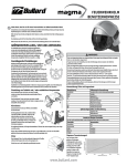
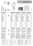
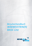
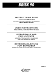
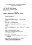
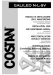
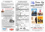
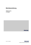
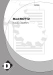
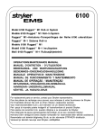
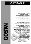
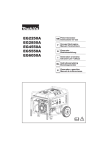
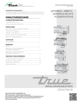
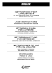
CE
CRONOS A3 - A0
USER MANUAL
READ CAREFULLY AND KEEP
GB
Cod.30438370
Pagina lasciata bianca appositamente. Blank page. Für künftige Einträge frei gelassene
Seite. Page laissée volontairement blanche. Pàgina dejada blanca expresamente.
Cod. 72004430 Pag. 1/1
MC - 27/03/2001
INDEX
INFORMATION ON MOVING THE CABINET,CABINET WEIGHT,POSITIONING
THE CABINET, SHELF AND DISPLAY PANS.................................................. 5
GENERAL DATES.................................................................................... 6
Cabinet noise level
Position of the drains............................................... 7
CABINET LABEL LEGEND.......................................................................... 8
GENERAL RECOMMENDATIONS................................................................. 10
Positioning the cabinet
Electrical connections and start-up
Preserving the product
Cleaning the cabinet................................................ 11
Cabinet maintenance
Instructions for the user
GLASS ASSEMBLY.................................................................................. 12
END WALL ASSEMBLY............................................................................. 15
MULTIPLEXIG OF CABINET....................................................................... 18
BUMPER RAIL ASSEMBLY......................................................................... 21
BACK SHELF EXTENSION ASSEMBLY......................................................... 23
THE SLIDING TRENCHER PLATFORM AND THE SCALE SHELF ASSEMBLY........ 24
LAE BIT 20 CONTROL PANEL.................................................................... 26
General description of the components
State of normal operation
User programming state............................................ 27
Numbers of times the cabinet must be defrosted
MANUAL SECTION RESERVED FOR INSTALLATION AND
ASSISTANCE PERSONNEL............................................................ 29
CLEANING OF THE CONDENSER................................................................ 31
SETTING OF WORKING PARAMETERS LAE BIT 20........................................ 32
Parameters modification
Parameters table
ELECTRICAL DIAGRAMS LEGEND.............................................................. 33
ELECTRICAL DIAGRAM LAE BIT 20............................................................ 35
GB - Cod. 72006680B Pag. 1/2
MC - 19/09/2005
ANGLES ELECTRICAL DIAGRAM................................................................ 36
GB - Cod. 72006680B Pag. 2/2
MC - 19/09/2005
CRONOS A3 - A0
INFORMATION FOR THE MOVING AND HANDLING THE CABINETS
The shaded part in the figure (
) and the symbol
labeled on back side of unit, indicates the gripping
area for lifting the unit with a fork-lift. The cabinet of: 1875, 2500, 3125 and 3750 mm can be handled by
inserting fork-lift prongs for a maximum depth of 730 mm from the back shelf. The cabinet of: 1250 mm, unit
not having enough space at the back for inserting the fork-lift prongs, must be lifted on pallet. If the unit is supplied
on a pallet or packing cage (both optional), handling is done by using these for lifting.
1875 - 2500 - 3125 - 3750
1250
WEIGHTH OF THE UNITS
Unit
Unit
Unit
Unit
Unit
Unit
CRONOS
1250 mm
1875 mm
2500 mm
3125 mm
3750 mm
AA90°mm
X A3
160 kg
215 kg
260 kg
315 kg
370 kg
-
A0
185 kg
NOTE: ALL THE MEASUREMENTS ARE QUOTED IN mm WITHOUT SIDES FITTED TO THE CABINETS.
POSITIONING THE CABINET
For transport and handling, the cabinet is supplied mounted on packing rods which are fitted to the feet of the
cabinet. Once the cabinet is in the final position within the store, remove the packing rods by unscrewing the
screws which fix the clips to the feet.
SHELF AND DISPLAY PANS
The maximum loads which can be supported are: on the middle shelf (optional) 8 kg/m ; for glass cover
20 kg/m, for display pans 90kg/m².
MAX 20 kg/m (Cronos A0 EC90°=0 kg/m)
MAX 90 kg/m²
GB - Cod. 72006670A Pag. 1/
3 MC - 07/07/2005
GENERAL INFORMATION
CRONOS A3 - CRONOS S A3 - CRONOS X A3 - CRONOS X S A3
Plug-in Cabinet with forced refrigerated air circulation for the displaying and the merchandising of meats, poultry,
cold cuts, dairy products and delicatessen. The unit is fully multiplexable and is also available with end walls (50
mm) or with a multiplexing kit.
Included : electronic control panel with automatic defrost, stainless steel display pans, paper holder, front bumper,
refrigerated back storage accessed by doors, ecoated evaporator with thermostatic valve, digital thermometer.
Supplied with superstructure not installed.
Available in the following models :
CRONOS A3 - refrigerated serve-over cabinet with lift-up glasses, without integral unit.
CRONOS S A3 - refrigerated self-service cabinet with lift-up glasses, without integral unit.
CRONOS X A3 - refrigerated serve-over cabinet with lift-up glasses, with integral unit.
CRONOS X S A3 - refrigerated self-service cabinet with lift-up glasses, with integral unit.
!! WARNING !!
The standard cabinet is supplied with a single extractable
tank for the collection of both defrost water and cleaning
water.
As an optional feature we are able to fit a second
automatic re-evaporation tank for the waste water.
For removal of this additional tank, it will be necessary to
remove the back panel of the cabinet.
BEFORE ELECTRICAL CONNECTION OF THE TANK FOR
AUTOMATIC RE-EVAPORATION OF THE WASTE WATER
(IF INSTALLED), IT IS NECESSARY TO CAREFULLY FILL
THE TANK WITH 2 LITRES OF WATER.
2
2l
CRONOS A0
Not refrigetared serve-over cabinet for the displaying and the merchandising of not perishable products. The
cabinet is multiplexable with multiplexing kit.
Included : 1 row of top canopy lighting with safety protection, stainless steel display pans, storage with
doors, switch for lighting, paper holder, front bumper. Supplied with superstructure not installed.
For the version A0 is available also outside corner 90° (EC90°).
Cronos A3
Cronos X A3
Cronos S A3
Cronos X S A3
Cronos A0
NOISE LEVEL OF THE CABINETS
The only sound emitted by the cabinet is that of the ventilator blades, which are necessary for cooling the cabinet
and eliminating condensation from the glass. The level registered by us, in accordance with the established
conditions set down by the EU Directive n. 89/392/CEE, is 55 ÷ 57 dBA.
GB - Cod. 72006670A Pag. 2/
3 MC - 07/07/2005
POSITIONS FOR WATER DRAIN, EVAPORATOR PIPES,
ELECTRIC CONTROL PANEL ON CABINETS
CRONOS X A3 - CRONOS A3 - CRONOS X S A3 - CRONOS S A3
1 : 50
Y
End wall
X
X = Washing water drain
Y = Defrost water drain
WARNING!
The measurements are expressed in mm, taking
the cabinet without end walls.
G
Position des pieds
W
Sortie eau
K
Sortie tubes évaporateur
E
Tableau de commande
pilote
L
T
G1
G2
G3
G4
G5
G6
W1
W2
W3
W4
K1
K2
E1
E2
1250
1088
25
40
1207
1224
120
730
972
1055
168
688
1229
188
195
420
1875
1088
25
40
1832
1849
120
730
1483
1748
168
688
1854
188
295
420
2500
1088
25
40
2457
2474
120
730
1795
1780
168
688
2479
188
295
420
3125
1088
25
40
3082
3099
120
730
2108
2333
168
688
3104
188
295
420
3750
1088
25
40
3707
3724
120
730
2488
2970
168
688
3729
188
295
420
CRONOS A0
EC90° Outside corner 90°
GB - Cod. 72006670A Pag. 3/
3 MC - 07/07/2005
TECHNICAL DATA FOR UNIT INSTALLATION
MADE IN ITALY
MODELLO:
MATRICOLA:
CODICE:
CONF.
VAR.:
ANNO DI COSTRUZIONE:
CLASSE CLIMAT. AMBIENTE EN 441:
CLASSE TEMPER. MOBILE EN 441:
POTENZA NOMINALE ASS.:
W
POTENZA ASS. SBRINAMENTO:
W
ALIMENTAZIONE
V
PH
Hz
ALTRI ASS:
W
V
A
W
V
A
W
V
A
CE
RoHS
FLUIDO FRIGORIG.:
LAMINAZIONE:
CAPACITA' CELLA:
SUPERFICIE ESPOSITIVA:
MAX PRESS. FUNZIONAMENTO:
CORRENTE NOMINALE:
CORRENTE SPUNTO:
UNITA' MOD:
W
V
W
V
W
V
Kg
L
M²
bar
A
A
A
A
A
RoHS
MADE IN ITALY
MODELE:
NUMERO DE SERIE:
CODE:
CONF.
SEZ.:
SEM. ANNEE DE FAB.:
CLASSE CLIMAT. AMBIANTE EN 441:
CLASSE TEMPER. MEUBLE EN 441:
PUISSANCE NOMINALES ABS.:
W
PUISSANCE ABS. DU DEGIVRAGE
W
TENSION:
V
PH
Hz
ABS. ACC.:
W
V
A
W
V
A
W
V
A
CE
Kg
L
M2
bar
W
V
V
V
RoHS
REFRIGERANT:
CT OU TXV:
V. RESERVE REFRIGEREE:
SURFACE D'EXPOSITION:
PRESSION MAXIMALE:
COURANT NOMINAL ABS.:
COURANT DEP. COMPRESSEUR:
MODELE DE UNITE:
W
V
W
V
W
V
Kg
L
M²
bar
A
A
A
A
A
The cabinet is compliant with RoHS European
Directive 2002/95/EC (only for plug-in cabinets).
KÄLTEMITTEL:
NUTZINHALT NACH DIN:
NUTZFLACHE NACH DIN:
ZUL.BETRIEBSÜBERDRUCK:
DICHTHEIT GEPRÜFT
V
Hz NENNAUFNAHME:
V
A
W
V
A
W
A TRÄGE
W
RoHS =
MADE IN ITALY
GERÄTE-NR.:
BAUJAHR:
KLIMAKLASSE NACH DIN8954:
FEUCHTIGKEITSSCHUTZ:
ERZEUGNIS - NR.
NENNSPANNUNG:
W
W
=
CE
GERÄTETYP:
The cabinet is subject to WEEE European Directive
2002/96/EC (only for plug-in cabinets).
The machine rating plate can be found near the electric control panel; in case of serve-over cabinets, otherwise
for wall cabinets and island-site cases it is placed inside the belly section. It contains all the information necessary
for identifying the unit and all the technical specifications which must be referred to for its correct installation and
consequent good operation.
Here below is an explanation on how to read the plate to obtain the necessary information:
GB - Cod. 72002520C Pag. 1/2
MC - 13/06/2006
Model of unit. Besides the name there are also the length in centimetres and the mark identifying the version.
Serial number of the cabinet (WHEN YOU REQUIRE A SPARE PARTS, YOU MUST ALWAYS INDICATE TOGETHER WITH THE
PRODUCT NUMBER).
Code for identifying the year of manufacture.
YEAR
ABB.
YEAR
ABB.
YEAR
1993
CG
1997
CA
2001
1994
CH
1998
CB
2002
1995
CI
1999
CC
2003
1996
CK
2000
DD
2004
ABB.
DE
DF
DG
DH
YEAR
2005
2006
2007
2008
ABB.
DI
DK
DA
DB
YEAR
2009
2010
2011
2012
ABB.
DC
ED
EE
EF
YEAR
2013
2014
2015
2016
ABB.
EG
EH
EI
EK
YEAR
2017
2018
2019
ABB.
EA
EB
EC
Climatic class. It is a number that indicates in what environmental conditions the unit functions correctly.
The number takes on the following meanings:
3 - the unit is suitable for operating with ambient temperature of 25°C and 60% relative humidity.
4 - the unit is suitable for operating with ambient temperature of 30°C and 55% relative humidity.
Temperature class of the unit. It is an abbreviation indicating the type of product that can be preserved during display.
The abbreviation takes on the following meanings:
L1 -
The unit is suitable for the preservation of frozen foods or industrial ice creams.
M1
- The unit is suitable for the preservation of fresh products among which meat and poultry.
M2
- The unit is suitable for the preservation of fresh products among which salamis and dairy products.
H
- The unit is suitable for the preservation of fresh products such as fruit and vegetables.
S
- The unit is suitable for the preservation of products with a special classification.
Maximum power absorbed by the unit, with full options installed, at its climatic class working conditions.
Electric power absorbed during defrosting of the unit evaporator.
Rated supply voltage, number oh phases and frequency the unit is suitable to function as. Before connecting the unit
electrically, check that it corresponds with that of the local mains electricity.
Electric power absorbed, rated voltage and current of the defrosting heaters, if provided with the unit.
Electric power absorbed, rated voltage and current of the demisting heaters.
Condensing unit model and/or type of compressor installed.
Type and quantity of refrigerant used in the cooling circuit of the unit.
Indicates if the evaporator is with capillary (CT) or thermostatic valve (TXV).
Net volume of the rear refrigerated storage (if installed).
Refrigerated display area available for displaying the goods.
Maximum operating pressure inside the cooling circuit of the unit.
Rated electrical power absorbed by the unit in normal operating conditions.
Rated electrical power absorbed by the unit during the compressor starting phase.
Electrical power absorbed, rated voltage and current of the lighting system of the unit.
Electrical power absorbed, rated voltage and current of the unit fans.
Electrical power absorbed, rated voltage and current of the of the condensing unit.
Cabinet level protection against humidity.
-Product number (WHEN YOU REQUIRE A SPARE PARTS, YOU MUST ALWAYS INDICATE TOGETHER WITH SERIAL NUMBER);
-configuration number.
Delayed fuse ampere.
Net volume usable of the cabinet.
Submitted to leak test.
Electrical power absorbed, rated voltage and current from other accessories electric installed (automatic re-evaporation of defrost
water, hot case, automatic overnight curtain etc.).
-Product number (WHEN YOU REQUIRE A SPARE PARTS, YOU MUST ALWAYS INDICATE TOGETHER WITH SERIAL NUMBER);
-configuration number;
-section number (indicated the position of multiplexed cabinet, starting from right hand for example A, B, C...).
GB - Cod. 72002520C Pag. 2/2
MC - 13/06/2006
GENERAL RECOMMENDATIONS FOR USE
-
-
-
-
-
-
POSITIONING THE UNIT
!WARNING! The cabinet must be positioned sheltered from sun and bad weather.
For unloading and handling of the unit with a fork-lift, refer to the gripping and lifting points indicated in this
pamphlet.
Once the unit has been positioned, remove the packing, including the bars fixed to the legs.
Check (on the rating plate) that the climatic class of the display case corresponds to that of the environment
in which it is to be installed.
The area where the display case is to be installed must be closed, avoiding contact by direct sunlight and
all the other sources of radiation like high-intensity incandescent light-bulbs, cookers and ovens, or radiating
bodies like heating system radiators.
Do not let drafts of over 0.2 m/sec hit the display case, so place it far from doors, windows, air conditioner
inlets/outlets.
For integral unit display cases:
a) Check that there is sufficient air exchange in the environment, even when the sales-room is closed.
b) Avoid blocking the air inlets to the condenser unit with products or other material placed on and around
the edges of the display case and with wall display cases keep it at least 5 centimetres from the wall.
For remote condenser unit cases, the unit set must avoid atmospheric agents, and the area must not be used
for storing material.
Remember that a rise in room temperature or an insufficient quantity of air to the condenser, not only
increases energy consumption, but also reduces the technical performance of the case with possible
deterioration of the products displayed.
Place the display case unit in a perfectly horizontal position, adjusting the level, if necessary, by turning the
screw feet of the case, and checking with a spirit-level. The unit must be perfectly level to operate correctly
and for the correct drainage of the water during defrosting; noisy vibrations of the motor are also avoided.
For cases with condensation collecting basins, make sure that these, and the drainage pipe, are positioned
correctly.
Before connecting the unit electrically it must be cleaned thoroughly using luke-warm water with neutral
detergents and then drying with a soft cloth.
!
ELECTRICAL CONNECTIONS AND START-UP
Electricity supply.
The electrical feeding plugs of accessories (i.e. electrical plugs) MUST BE CONNECTED TO SOCKETS WITH
SEPARATE SAFETY CIRCUIT BREAKER.
BEFORE ELECTRIC CONNECTION OF THE TANK FOR AUTOMATIC RE-EVAPORATION OF THE WATER
DISCHARGE (IF FITTED) IT IS NECESSARY TO SLOWLY POOR 2 LITRES OF WATER INSIDE IT. THIS OPERATION
IS NOT NECESSARY WITH INOX TANK.
The frequency and mains electricity supply voltage must correspond to what is on the case rating plate.
Check that the supply voltage at the socket is ± 10% the rated voltage at the moment the compressor is
started up.
Grounding of the case is obligatory.
Fitting an omni-polar power isolator switch with a contact gap of at least 3 mm, upstream of the socket is
recommended. This switch is obligatory when the load is over 1000 W or when the case is connected directly
without the use of a plug. In case of failure and to avoid having to switch off the whole circuit, it would be
advisable to replace the power isolator switch with a high sensitivity differential magneto-thermal cut-out
switch.
Start-up of the display case.
For global unit cases, check that the power isolator switch is open - in position 0, OFF or green - before
plugging in. Plug in and close the switch.
For remote unit cases initial start-up must be done by specialised personnel.
For the adjustment of operation parameters consult the instructions for use on the control panel.
Avoid setting temperatures lower than those corresponding to the category of the case; no extra benefit
would derive from it and the evaporator will become blocked.
The best sign of good operation is given by the temperature shown by the thermometer in the case.
The indications supplied by the graduated scales of the thermostats could differ from the reading on the
thermometer and therefore should not be retained valid for verifying the good operation of the case.
RECOMMENDATIONS FOR BEST PRESERVING THE PRODUCT
Product load
The display cases are suitable for displaying pre-refrigerated products that must come from the warehouses
at a temperature close to the ideal preservation temperature. The quality of the goods also depends on how
they had been treated before they arrived at the sales point. Frozen products must have a temperature that
GB - Cod. 72000020B Pag. 1/2
MC - 13/07/2005
-
-
-
-
-
-
-
-
is not above -18 °C. Loading products still to be cooled worsens all the operating conditions, with the risk of
damaging the goods already on display. So, when products come from the suppliers, they must immediately be
put in the display cases or in the cold rooms to avoid excessive loss of cold due to their standing in warm places.
To have the display case operate properly the product must be set out in such a way that the circulation of cold
) and avoid placing the
air is not impeded. So observe the red maximum load line on the display case (
product above it. The goods placed above this line are not cooled and could cause the formation of frost on the
evaporator, thus worsening the thermal conditions of those products placed correctly. Furthermore avoid blocking
the air-intake placed on the front part of the display shelf.
The drawers and doors of the service cases and the doors of the cabinets must be opened only for the time strictly
necessary for loading and unloading the products to avoid excessive loss of cold.
Keep all meat, even when sectioning, in cold-rooms. When the work goes on for more than two minutes put them
back in the cold-store to chill.
The units are equipped with an automatic daily defrosting system, factory pre-set according to need. In some cases
it may still be necessary to carry out manual defrosting by stopping the compressor with the appropriate control.
This is necessary when there is a loss or reduction of the cold air flow at the air outlet area. This means that the
evaporator is packed with ice and hinders the correct circulation of air.
For energy saving and a correct keeping of the product, it would be advisable to use covers or roller shutters
(optional), when the shop is closed.
CLEANING THE UNIT
The display case must be cleaned at regular intervals. Before starting cleaning, unplug the display case from
the mains supply. Do not use water under pressure for washing. Only use luke-warm water with alittle nonabrasive detergent, then drying the parts with a soft cloth. The frequency with which cleaning is carried out
varies according to the product on display. The maintenance of a display case used for preserving products
such as meat, salamis, and dairy products must include at least one weekly cleaning of the loaded area to
avoid the development and the accumulation of bacteria. A weekly wash is recommended for the the case
inside-bottom especially for units subjected to spilling of liquids or other food residues.
Daily cleaning with water and detergent must be done, even in the external areas which surround the display
area: this makes the display case more attractive and prevents dirt from forming.
Units for frozen food and ice-creams should have the case bottom cleaned at least once a month.
Cleaning the condenser.
This must be done, in normal conditions of use, at least once a month, using a vacuum cleaner and a brush
with hard bristles. It is best to use gloves, seeing that the small space between the fins could cause bruising.
A dirty condenser reduces the performance of the motor with a consequent increase in electricity
consumption.
In the units with the condenser collection basin, drain the water daily.
!
UNIT MAINTENANCE
At regular intervals, at least once a year, have qualified personnel check the perfect operation of the system,
making sure that there are no coolant leaks and that the state of maintenance of the electrical system is
completely safe.
When replacing burnt-out lamps unplug the unit or open the power isolator switch (position 0, OFF or green).
remove the transparent plastic protection from the lamp;
take the lamp at the two ends and turn it 90° until a slight click is heard, then remove it being careful not
to knock it against anything;
to fit the new lamp insert it and turn it as above and put back the plastic protection.
INSTRUCTIONS FOR THE USER
in the units equipped with a glass top, the glass top must be raised until it reaches maximum opening and
kept open only for the time strictly necessary for loading and unloading or for cleaning. In normal conditions
of use the glass must remain lowered. The two pistons with which each glass is equipped aid lifting and are
a safety measure against the glass top suddenly dropping shut. It is important therefore that their efficiency
is regularly checked.
An increased effort in opening the glass top means that the performance of one or both the pistons is
decreasing and that it is therefore necessary to replace them with the help of qualified personnel.
Avoid displaying goods on the canopy of glass tops that have no front support.
When cleaning the inside of the unit case, once the display shelves for the goods have been removed (using
the appropriate tool), be careful not to get hurt by the fins of the evaporator since they can be very sharp.
In those units with electrical defrosting be careful not to get burnt by the resistance elements that could still
be hot because you have only switched it off.
With units heated by infra red lamps take care not to get a burn from the hot parts such as the lamp holders
and the lamp itself.
GB - Cod. 72000020B Pag. 2/2
MC - 13/07/2005
CRONOS A3
MONTAGE DER AUFSATZ - GLASS ASSEMBLY - MONTAGE DE VITRINE
MONTAGGIO VETRINA - MONTAJE SOBRESTRUCTURA VIDRIADA.
30’
1
2
3
4
1
Cod. 72006810 Pag. 1/3
MC - 28/04/2004
5
6
7
8
9
10
Cod. 72006810 Pag. 2/3
MC - 28/04/2004
11
12
13
14
15
16
17
18
Cod. 72006810 Pag. 3/3
MC - 28/04/2004
CRONOS A3
SEITENWÄNDE MONTAGE - END WALL ASSEMBLY - MONTAGE JOUE
MONTAGGIO FIANCATA - MONTAJO LATERAL
5
8
4
3
9
7
6
2
1
10
15’
1
8 mm
N°
DESCRIPTION - DESCRIPTION - BAUTEIL - DESCRIZIONE - DESCRIPCION
1 Panoramascheibe - Panoramic end wall - Joue panoramique - Fiancata -
Costado.
Q.
M.
1
Seitenscheiben - Glass side - Joue vitrée - Vetro termopane - Lateral vidrio.
2
1
Seitenscheiben LS - Glass side LS - Joue vitrée LS - Vetro termopane LS - Lateral vidrio LS.
3
Befestigung Winkel - Holder profile - Support de fixation
Supporto fissaggio vetro - Soporte de fijado.
3
4
Schraube TPS 3,9x13 mm - Screw TPS 3,9x13 mm - Vis TPS 3,9x13 mm
Vite TPS 3,9x13 mm - Tornillos TPS 3,9x13 mm.
6
5
Gummi Profil 50x3 mm - Adhesive mousse 50x3 mm - Gomme isolante 50x3 mm
Gomma isolante 50x3mm - Engoma aislante 50x3 mm.
3 M.
6 Testina cappello - Head hat - Couverture chapeau - Kopf Zahlplatte - Cabeza superior
1
Schraube ZN TCEI 5x20 mm - Screw ZN TCEI 5x20 mm - Vis ZN TCEI 5x20 mm
Vite ZN TCEI 5x20 mm - Tornillos ZN TCEI 5x20 mm.
2
7
8 Scheiben ZN D. 5 - Washer ZN D. 5 - Rondelle ZN D. 5 - Rosetta ZN D. 5 - Arandela ZN D. 5
9
10
2
Schraube ZN TEC 6,3x60 mm - Screw ZN TEC 6,3x60 mm - Vis ZN TEC 6,3x60 mm
Vite ZN TEC 6,3x60 mm - Tornillos ZN TEC 6,3x60 mm.
3
Schraube ZN TC 4,8X19 mm - Screw ZN TC 4,8X19 mm - Vis ZN TC 4,8X19 mm
Vite ZN TC 4,8X19 mm - Tornillos ZN TC 4,8X19 mm.
2
Cod. 72006840 Pag. 1/3
MC - 07/05/2004
5
5
1
2
9
9
3
4
1
9
10
5
1
6
3
4
10
7
8
Cod. 72006840 Pag. 2/3
MC - 07/05/2004
6
8
7
6
9
10
2
11
12
Cod. 72006840 Pag. 3/3
MC - 07/05/2004
CRONOS
ZUSAMMENBAU DER KÜHLTHEKE - MULTIPLEXUNG OF CABINET
CANALISATION DU MEUBLE - CANALIZZAZIONE DEL MOBILE
CANALIZACION DEL MUEBLE
3
1
2
6
12
14
15’
10
1
9
11
8
13
15
17
7
16
4
N°
1
2
3
4
5
6
7
5
BAUTEIL - DESCRIPTION - DESCRIPTION - DESCRIZIONE - DESCRIPCION
Front Stoßblende - Front cover multiplexing - Couverture antérieur canalisation
Fascia canalizzazione anteriore - Cobertura faja canalizaciòn anterior
Hiterer Stoßblende - Rear cover multiplexing - Couverture postérieur canalisation
Fascia canalizzazione posteriore - Cobertura faja canalizaciòn posterior
Arbeitsplatte Stoßblende - Back shelf cover multiplexing - Couverture tablette de travail canalisation
Fascia canalizzazione piano lavoro - Cobertura faja canalizaciòn plano de trabajo
Erde Kabel - Earth cable - Fil de terre - Cavo terra - Cable de tierra
12
13
14
15
16
17 Mutter ZN M8 - Nut ZN M8 - Ècrou ZN M8 - Dado ZN M8 - Tuerca ZN M8
1
14
2
Schraube ZN TGS 2,9x9,5 mm - Screw ZN TGS 2,9x9,5 mm - Vis ZN TGS 2,9x9,5 mm
Vite ZN TGS 2,9x9,5 mm - Tornillos ZN TGS 2,9x9,5 mm.
Schraube ZN TE M8x120 mm - Screw ZN TE M8x120 mm - Vis ZN TE M8x120 mm
9
Vite ZN TE M8x120 mm - Tornillos ZN TE M8x120 mm.
Scheibe 8,4 mm - Washer 8,4 mm - Rondelle 8,4 mm
10
Rosetta 8,4 mm - Arandela 8,4 mm
Spannstift 4x40 mm (Für Zahlplatte Glaszwischenauslage)
Flexble pins 4x40 mm (For interim glass shelf top canopy overhead)
Fiche élastique 4x40 mm (Pour tablette supérieure etagère interédiarie)
Spina elastica 4x40 mm (Per plafoniera mensola intermedia)
Espina elàstica 4x40 mm (Por lámpara de cielo repisa intermedia)
Verbindungsplatte der Konsolen - Union plate - Plaque jonctin
Piastra di canalizzazione - Plaqueta uniòn
Spannstift 5x40 mm - Flexble pins 5x40 mm - Fiche élastique 5x40 mm
Spina elastica 5x40 mm - Espina elàstica 5x40 mm
Zylinderstift 4x40 mm - Split pins 4x40 mm - Fiche cylindrique 4x40 mm
Spina cilindrica 4x40 mm - Espina cilindrica 4x40 mm
Schraube ZN TE M6x16 mm - Screw ZN TE M6x16 mm - Vis ZN TE M6x16 mm
Vite ZN TE M6x16 mm - Tornillos ZN TE M6x16 mm.
1
6 M.
Zahnscheibe - Toothed washer - Rondelle denté - Rosetta dentata - Arandela lobulada
11 Mutter ZN M8 - Nut ZN M8 - Ècrou ZN M8 - Dado ZN M8 - Tuerca ZN M8
1
1
Gummi Profil 50x3 mm - Adhesive mousse 50x3 mm - Gomme isolante 50x3 mm
Gomma isolante 50x3mm - Engoma aislante 50x3 mm.
Schraube ZN TC 4,8x13 mm - Screw ZN TC 4,8x13 mm - Vis ZN TC 4,8x13 mm
Vite ZN TC 4,8x13 mm - Tornillos ZN TC 4,8x13 mm.
8
M. - Q.
4
3
6
3
2
1
2
3
3
1
Cod. 72006890 Pag. 1/3
MC - 19/05/2004
15
2
1
3
14
13
5
4
5
14
13
6
8
7
15
Cod. 72006890 Pag. 2/3
MC - 19/05/2004
9
9
9
9
11
10
9
10
16
17
12
11
7
6
6
2
1
13
6
14
3
15
4
16
7
16
Cod. 72006890 Pag. 3/3
MC - 19/05/2004
MONTAGE DER STOSSLEISTE - BUMPER RAIL ASSEMBLY - MONTAGE DE PARE-CHOCK
MONTAGGIO BATTICARRELLO - MONTAJE DE PARA GOLPES
1
15’
1
4
3
10
9
1
2
5
8
N°
1
7 6
BAUTEIL - DESCRIPTION - DESCRIPTION
DESCRIZIONE - DESCRIPCION
Stoßleiste - Bumper rail - Pare-chock - Tubo batticcarrello - Para golpes
Frontstütze - Front support - Support avant
Mensola frontale - Sostén anterior
Endkappe für Wagenabweiser - Bumper rail head - Testina batticarrello
3
Bouchon pare chock - Cabezal por para golpes
Gummi Stoßleiste - Bumper rail mousse - Gomme pare chock
4
Gomma batticcarrello - Engoma para golpes
Winkelteil für Stoßleiste - Bumper rail support profile
5 Angulaire support pare-chock - Angolare batticarrello
Angular para golpes
Schraube ZN TE M8x15 mm - Screw ZN TE M8x15 mm
6 Vis ZN TE M8x15 mm - Vite ZN TE M8x15 mm
Tornillos ZN TE M8x15 mm
Scheiben 8,4 mm - Washer 8,4 mm - Rondelle 8,4 mm
7
Rosetta 8,4 mm - Arandela 8,4 mm
Mutter ZN M8 - Nut ZN M8 - Ècrou ZN M8
8
Dado ZN M8 - Tuerca ZN M8
Schraube ZN TC 4,8x25 mm - Screw ZN TC 4,8x25 mm
9 Vis ZN TC 4,8x25 mm - Vite ZN TC 4,8x25 mm
Tornillos ZN TC 4,8x25 mm
Schraube ZN TC 3,9x13 mm - Screw ZN TC 3,9x13 mm
10 Vis ZN TC 3,9x13 mm - Vite ZN TC 3,9x13 mm
Tornillos ZN TC 3,9x13 mm
2
Q. / M.
1250
1875
2500
3125
3750
1
1
1
1
1
2
3
3
4
4
2
2
2
2
2
1,5 M.
2 M.
1
1
2
2
2
2
3
3
4
4
2
3
3
4
4
2
3
3
4
4
6
9
9
12
12
2
2
2
2
2
2,6 M. 3,2 M. 3,9 M.
Cod. 72007160 Pag. 1/3
MC - 15/11/2004
5
1
5
2
A
A
B
B
A
A
A
B
A
A
A
A
B
A
A
A
A
B
A
A
A
A
B
2
9
1
2
4
3
4
Cod. 72007160 Pag. 2/3
MC - 15/11/2004
1
3
6
1
5
6
1
10
3
6
7
8
7
8
9
10
ZUSAMMENBAU / MULTIPLEXING / CANALISATION / CANALIZZAZIONE / CANALIZACION
Spannstift 4x40 mm
Flexble pins 4x40 mm
Fiche élastique 4x40 mm
Spina elastica 4x40 mm
Espina elàstica 4x40 mm
Cod. 72007160 Pag. 3/3
MC - 15/11/2004
MONTAGE DER ARBEITSPLATTEN VERBREITERUNG - BACK SHELF EXTENSION ASSEMBLY
ASSEMBLAGE DE EXTENSION TABLETTE DE TRAVAIL - MONTAGGIO ESTENSIONE PIANO DI LAVORO
MONTAJE EXTENSIÓN PLANO DE TRABAJO
1
BAUTEIL - DESCRIPTION - DESCRIPTION
DESCRIZIONE - DESCRIPCION
N°
1
2
2
2
3
2
3
Arbeitsplatten Verbreiterung - Back shelf extension
Extension tablette de travail - Estensione piano di lavoro
Extensión plano de trabjo
Arbeitsplatten Verbreiterung für Stoßleiste
Back shelf extension support profile
Angulaire support Extension tablette de travail
Angolare Estensione piano di lavoro
Angular Extensión plano de trabjo
Schraube ZN TC 4,8x13 mm
Screw ZN TC 4,8x13 mm
Vis ZN TC 4,8x13 mm
Vite ZN TC 4,8x13 mm
Tornillos ZN TC 4,8x13 mm
Q. / M.
3
3
3
3
1250
1875
2500
3125
3750
1
1
1
1
1
2
2
3
3
3
10
10
15
15
15
2
2
2
2
1
3
3
1
1
2
3
3
4
5’
1
5
Cod. 72007190 Pag. 1/1
MC - 09/12/2004
MONTAGE DES VERSCHIEBBAREN SCHNEIDBRETTS - THE SLIDING TRENCHER PLATFORM ASSEMBLY
MONTAGE PLANCHE À DECOUPER COULISSANTE - MONTAGGIO TAGLIERE SCORREVOLE
MONTAJE TABLA DE CORTE CORREDIZA
1
2
MONTAGE DES WAAGENTISCH - THE SCALE SHELF ASSEMBLY - MONTAGE PORTE-BALANCE
MONTAGGIO PORTABILANCIA - MONTAJE PORTABALANZA
1
2
Cod. 72007200 Pag. 1/1
MC - 13/12/2004
CONTROL PANEL LAE BIT
Defrost pilot lamp
Defrost pilot lamp
Compressor operation pilot lamp
Compressor operation pilot lamp
Regulator operation pilot lamp
The Bit20 controller and the magneto-thermal main switch are situated inside the cabinet supply control panel.
On the rear panel of the special leg cover, there is a Bit12 keyboard fitted with operator interface, which contains
a 2-figure display, keyboard with 3 function keys and two bipolar switches.
GENERAL DESCRIPTION OF THE COMPONENTS
I - ON
Main magneto-thermal differential switch.
When “OFF” the switch is on “0” it disarms all the functions connected with the control panel; when
“ON” the switch is on “I” (if present).
0 - OFF
Bit20 regulator for controlling cabinet temperature.
Bit12 keyboard for setting and controlling the Bit20 regulator parameters.
STATE OF NORMAL OPERATION
During normal working, the display shows the actual temperature inside the cabinet, by using the keys the
following functions are controlled:
Display the set point value;
Programming key, to be used by a qualified person,
if it is pressed it increases the value associated with the parameter.
Programming key, to be used by a qualified person,
if it is pressed it decreases the value associated with the parameter.
This pushbutton works as a master switch and switches off the counter while leaving the lighting system
on (If included). This pushbutton lights up when pressed in the "ON" position.
This pushbutton switches the demisting fans on and lights up when pressed in the "ON" position (or
demisting heater). This pushbutton must be used whenever the counter is positioned in rooms
with excessive humidity in the air, to avoid misting of the front glasses (If included).
This pushbutton switches the top canopy lighting and the intermediate shelf lighting (if provided). When
pressed, the pushbutton goes into the "ON" position.
The display also shows, by lighting a led, the operation state of the compressor, of the ventilators and the
defrosting cycle.
GB - Cod. 72005680B Pag. 1/2
MC - 25/11/2004
USER PROGRAMMING STATE
The SET POINT, which governs the working temperature for the cabinet, has already been set in the factory
and is given in the parameter table. If this value needs changing, the user must press and keep pressed the
key
, the set value is displayed, pressing keys
to the required level.
To end the operation press the key
and
the displayed value can be increased decreased
. The operating temperature to be set on the electronic board must coincide
with that indicated by the producer of the goods on display (see recommended preservation temperatures on the
packing of the product).
NUMBER OF TIMES THE UNIT MUST BE DEFROSTED
The number of daily defrostings is already set in the factory, and they are evenly and automatically spread
throughout the day. Defrosting starts automatically each time the inside timer reaches the required temperature
to obtain the desired defrosting frequency. THE TIMER IS ZEROED WHEN THE CONTROLLER IS TURNED ON
AND WITH EACH SUCCESSIVE DEFROSTING START UP.
The number and time of daily defrostings change of the cabinet version and defrosting type:
KLEO X - OPALIA X
- Defrosting by simply stopping the refrigeration: 3 cycles maximum duration 60 minutes;
- Electric defrosting (optional): 3 cycles maximum duration 40 minutes;
MIDA X
- Defrosting by simply stopping the refrigeration: 3 cycles maximum duration 60 minutes;
- Electric defrosting: 3 cycles maximum duration 60 minutes;
NABUCCO STATIC FISH
- cabinet with automatic defrost: this cabinet does not need defrosting;
- cabinet with electric defrost (accessories): 3 cycles of 60 minutes;
NABUCCO STATIC MEAT
- cabinet with automatic defrost, only for cabinet with Glycol refrigerant: 3 cycles of 60 minutes;
- cabinet with electric defrost: 3 cycles of 60 minutes;
CRONOS, DORIS and GLYCOS
- cabinet with automatic defrost: 4 cycles maximum duration 60 minutes.
- cabinet with electric defrost (optional Cronos and Doris): 4 cycles maximum duration 30 minutes.
Should an immediate defrost be required, press keys
and
simultaneously for 2 seconds.
During the defrosting cycle, the display shows the last temperature taken before beginning the cycle.
GB - Cod. 72005680B Pag. 2/2
MC - 25/11/2004
Pagina lasciata bianca appositamente. Blank page. Für künftige Einträge frei gelassene
Seite. Page laissée volontairement blanche. Pàgina dejada blanca expresamente.
Cod. 72004430 Pag. 1/1
MC - 27/03/2001
DOCUMENTATION FOR EXCLUSIVE
USE OF THE INSTALLATION AND
ASSISTANCE PERSONELL
GB - Cod. 72004390 Pag. 1/1
MC - 19/03/2001
Pagina lasciata bianca appositamente. Blank page. Für künftige Einträge frei gelassene
Seite. Page laissée volontairement blanche. Pàgina dejada blanca expresamente.
Cod. 72004430 Pag. 1/1
MC - 27/03/2001
REINIGUNG DES KONDENSATORS - CLEANING OF THE CONDENSER - NETTOYAGE DU
CONDENSEUR - PULIZIA DEL CONDENSATORE - LIMPIEZA DEL CONDENSADOR
CRONOS - DORIS - GLYCOS
b
1
2
3
4
5
6
c
a
Cod. 72007560 Pag. 1/1
MC - 19/09/2005
SETTING OF WORKING PARAMETERS OF BIT LAE CONTROL PANEL
(Only for qualified personnel)
The chart has a non-volatile memory, which registers the work input through the parameters that can be
programmed using the front keys, with the chart working.
PARAMETERS MODIFICATION:
The display must be on normal working (showing the room temperature of the cabinet);
• Press
+
+
simultaneously for more than 4 seconds until the code “SP” appears;
• Release the keys and check the display shows "SP", code for the first parameter that can be changed;
• press and keep pressed the key
, to change the value associated with the parameter, and with keys
and
the displayed value can be increased or decreased to the required level;
• release the key
, the controller passes automatically to the next parameter;
• repeat the procedure from the beginning "press
and/or
..." to change the other parameter values.
To exit:
do not press any key for at least 60 seconds (TIME OUT).
PARAMETERS TABLE FOR CABINET WITH LAE BIT CONTROL PANEL
CRONOS A3
DORIS A3
72007000
72007010
01/10/2004
01/10/2004
SP
Main set point
U.M. aut.defrost elec.defrost
°C/°F
2
2
SL
Minimum set allowed
°C/°F
SH
Maximum set allowed
°C/°F
HY
Main thermostat delay
°C/°F
CR
Compressor stop
min
CF
Compressor safety run in case of probe failure 00=40%…01=100%
n°
DF
Defrosting frequency
n°
DT
Maximum defrosting duration
min
DL
Defrosting end temperature
DM
Type of defrost (00=Stop compr./01=Electric/02=Gas)
DR
Dripping time
min
TH
Display control during defrosting
min
TO
Offset of displayed temperature
°C/°F
TS
Slowdown of displayed temperature
°C/°F
–
–
-10
15
2
03
00
4
60
12
00
2
10
00
03
-10
15
2
03
00
4
30
12
01
2
10
00
03
GB - Cod. 72007000 Pag. 1/1
MC - 26/11/2004
LEGEND FOR THE PLUG IN ELECTRICAL DIAGRAMS
Terminals 6 to 8 = contact output N.O. MAX. 2A (remove jumper from terminals 5 and 6).
Terminals 8 to 10 = refrigeration output 230V 50Hz 1PH+N MAX. 2A.
Electric panel.
Lighting ballast box.
Control dash-board.
Display case length.
Lamps/ballast rated electrical powers.
Rated power referred to 230 Vac 50 Hz mains supply.
Refrigeration outlet max. 2A AC3.
Auxiliary outlet.
Alarm outlet.
Presence and features of electrical components or user elements.
Only fitted to ventilated cabinets.
Only fitted to counter service cabinets.
230 Vac 50 Hz supply, 1PH+N+Gnd.
Refrigerated unit control electric wiring diagram.
8-11 = N.O. clean contact refrigerator outlet (remove cable 32 in terminals 10 and 11).
8-9 = 230 Vac 50 Hz refrigeration outlet, max. 6A AC1.
AA
AC
A31
A58
A67
B15
B23
B24
B25
C01
D00
D14
E00
E02
E03
E10
F0G
F00
F03
F05
F001
F002
F14
F4A1
F4A2
K00
K001
K002
Open angle.
Closed angle.
Control card for refrigerated unit.
Display card.
Speed change for motor-driven fan.
Control level water switch.
Evaporator temperature probe.
Room temperature probe.
Temperature probe on the air suction circuit.
Lighting rephase capacitor.
Compressor 2 delaying device.
Timer.
Upper lighting.
Anterior front apron lighting - optional.
Interim shelf lighting.
Condenser unit.
A31 card primary fuse.
Refrigeration outlet fuse.
Fuse for R34-E00-E03-R11.
Fuse for auxiliaries M66-M111-M112.
Compressor 1 fuse.
Compressor 2 fuse.
Klixon for end defrost safety.
Compressor 1 high pressure pressure switch.
Compressor 2 high pressure pressure switch.
Remote switch for refrigeration outlet.
Compressor 1 remote switch.
Compressor 2 remote switch.
GB - Cod. 72000240C Pag. 1/2
MC - 31/05/2005
K11
L0_
M011
M012
M111
M112
M3A
M66
Q27
Q29
Q30
R-C
R11
R34
R37
S13
S17
S171
S172
S19
S4B
Remote control switch for defrosting heaters.
Fluorescent lamp ballast.
Motor driven compressor n° 1.
Motor driven compressor n° 2.
n° 1 Condenser unit fan.
n° 2 Condenser unit fan.
Demisting fans.
Evaporator motor driven fans.
Magneto-thermic switch for lights.
Magneto-thermic master switch E.M.F.
Differential magnetothermal switch.
Anti-noise filter.
Evaporator defrost resistance element.
Anti-fog resistance element.
Re-evaporation water heater.
Anti-fog resistance element switch.
Display case lighting switch.
Line n° 1 light switch.
Line n° 2 light switch.
Display case supply switch.
Night temperature thermostat (only with night cover) remove the cable that is between terminals 4
and 5.
S4I
Safety heater thermostat.
S44
End-defrost thermostat.
S45
Temperature thermostat.
SV1
Selector feeding re-evaporation resistance.
T1
Room temperature probe.
T2
Evaporator temperature probe.
T3
Temperature probe on the air suction circuit.
T3A
Controller supply transformer for refrigerated unit.
VMT Grounding screw.
V0
Fluorescent lamp.
W00 Flat.
XA
Terminal block for to be earth-wire wiring.
XF
Male faston on the control card.
XPE
Cabinet bar terminal block for ground cables.
XPQ
Connector between control panel-electric panel.
X2C
2 poles terminal.
X2I
Insulation derivation terminal.
X00
User connector terminal board.
X00_1 Display case supply terminal box.
X00_2 Terminal box for defrost resistance element outlet and condenser unit or solenoid valve.
L-N = refrigeration outlet. 220 Vac 50 Hz max. 2A (AC3).
X40
Power supply connection for re-evaporatin water heater.
X50
Plug for the re-evaporatin water heater.
X60
Display case supply plug. Connect to mains 220/230 Vac 50 Hz.
X61
Electric socket for cabinet multiplexing.
Y13
Liquid line solenoid valve.
Y15
Hot-gas defrost solenoid valve.
GB - Cod. 72000240C Pag. 2/2
MC - 31/05/2005
Pagina lasciata bianca appositamente. Blank page. Für künftige Einträge frei gelassene
Seite. Page laissée volontairement blanche. Pàgina dejada blanca expresamente.
Cod. 72004430 Pag. 1/1
MC - 27/03/2001