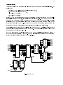
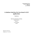
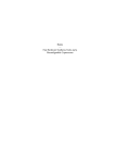
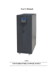
1
ABCD
Eidgenössische
Technische Hochschule
Zürich
Departement Informatik
Institut für
Computersysteme
Hans Eberle
Stephan Gehring
Stefan Ludwig
Niklaus Wirth
Tools for Digital Circuit
Design using FPGAs
May 1994
215
2
ETH Zürich
Departement Informatik
Institut für Computersysteme
Prof. Dr. N. Wirth
Authors' addresses:
Institut für Computersysteme, ETH Zentrum, CH−8092 Zürich, Switzerland
e−mail: eberle, gehring, ludwig, [email protected]
(c) 1994 Departement Informatik, ETH Zürich
3
Tools for Digital Circuit Design using FPGAs
H. Eberle, S. Gehring, S. Ludwig, N. Wirth
Preface
This collection of five papers describes concept and facilities of a system to aid in the design of digital
circuits. It is being used in classes and laboratories for circuit design, and also for the development of
prototype circuits in research projects.
The first paper by N. Wirth describes a basic formalism for the specification of digital circuits. It is called
Lola for Logic Language. Although its syntax mirrors that of programming languages, its "programs"
describe static circuits rather than dynamic processes. Its features encourage a structured design, allowing
components of the same type to be instantiated like structured variables in programming languages.
The second paper by S. Gehring gives an introduction to field programmable gate arrays, in particular the
Atmel 6000 architecture used in our laboratories. The Atmel 6002 features 32x32 fine−grained cells
organized in 8x8 blocks. Each cell implements routing or logic functions and contains a register. The
connection network is hierarchical and consists of neighbour connections and a bus structure consisting
of local and express busses.
The third paper by S. Ludwig explains the use of an editor for specifying implementations of circuits based
on a field programmable gate array (FPGA). The editor makes it possible to design a layout for a circuit
interactively. Individual components of the circuit are mapped onto the available FPGA cells visible on the
workstation's display. The editor displays the various possibilities offered by a selected cell in the form of
graphical menus.
The topic of the fourth paper by S. Gehring is a program which tests the compatibility of a layout with a
circuit specification formulated in Lola. This Checker is based on an abstract data structure which the Lola
compiler generates, as well as on the internal layout representation generated by the editor. This data
structure is also used by simplification, analysis, and simulation tools.
The final paper by H. Eberle and N. Wirth specifies the extension of the Ceres workstation containing the
gate array, an Atmel 6002 chip with 1024 cells. It is implemented as a small additional circuit board
interfacing directly with the Ceres processor bus like an I/O device. A few additional components are
connected to the FPGA, which are useful in various class exercises. These are a 32K x 8 SRAM, line drivers
for RS−232 and RS−485, a crystal oscillator, a DA and an AD converter, an electrically programmable PLD,
and a DRAM.
4
Lola: An Object−Oriented Logic Description Language
N. Wirth
Introduction
Lola is a notation (language) for specifying synchronous, digital circuits (logic). In many ways it resembles
a procedural programming language. However, Lola texts describe static circuits rather than dynamic
processes. The objects occurring in a description are variables representing signals, operators representing
gates, and composite structures of such objects.
1. Identifiers, Integers, Logical Values, and Comments
Identifiers are used to denote constants, variables, and types.
identifier =
integer =
LogicValue =
letter {letter | digit} ["'"].
digit {digit}.
" '0" | " '1".
Comments are sequences of characters enclosed by the brackets (* and *), and they may occur between
any two symbols within a Lola text.
2. Basic and Simple Types
Every variable in Lola has a type. It is either a basic, predefined type or a structured type defined in the
program text. The basic types are denoted by BIT, TS, or OC, which differ only in their rules governing
assignment. (TS denotes a tri−state bus, OC an open−collector bus). Variables of a basic type have a logic
value, denoted by '0 or '1.
SimpleType = BasicType | identifier ["(" ExpressionList ")"].
BasicType =
"BIT" | "TS" | "OC".
ExpressionList = expression {"," expression}.
3. Array types
Array types consist of an array of elements, all of which have the same type. A numeric expression
indicates the number of elements in the array. Elements are identified by an index value. Indices range
from 0 to the array's length minus 1.
type =
{ "[" expression "]" } SimpleType.
4. Constant Declarations
Constant declarations serve to introduce identifiers denoting a constant, numeric value.
ConstDeclaration = identifier ":=" expression ";".
5. Variable Declarations
Variable declarations serve to introduce identifiers denoting a logic variable and to associate it with a type.
All variables declared in an identifier list have the same type.
VarDeclaration =
IdList =
IdList ":" type ";".
identifier {"," identifier}.
5
6. Expressions
Expressions serve to combine variables with logical operators to define new values. The operators are the
negation, the logical conjunction (and), disjunction (or), and difference (xor). Operands are of any basic
type. Elements of an array are selected by an index: a.5, a.i. If the index is an expression, the form a[exp]
is used.
+
logical disjunction (or)
−
logical difference (exclusive or)
*
logical conjunction (and)
˜
negation (not)
A multiplexer is denoted by MUX(s: a, b) and is equal to ˜s*a + s*b. The abbreviation MUX(s1, s0: a, b, c,
d) stands for
MUX(s1: MUX(s0: a, b), MUX(s0: c, d)).
A register provides the means to specify a value depending on previous values in time (sequential circuit).
The value of REG(e, d) in the next clock cycle is equal to d in the current clock cycle, if e = '1. If e = '0, the
previous value is retained. e is called the register's enable signal. The clock signal does not appear
explicitly, but is assumed to be the same implied clock for all registers (synchronous circuit). The short
notation REG(d) stands for REG('1, d).
A latch, denoted by LATCH(e, d), is a storage element which holds a logic value while e = '0. If e = '1, the
value d is acquired (and the latch is transparent).
A basic SR−flipflop with (active−low) set and reset signals is expressed as SR(s', r').
Apart from logic expressions there exist numeric expressions. They follow the same rules of composition;
their operators are those of addition, subtraction, multiplication, division, and power of 2 denoted by ↑
(e.g. ↑4 = 16).
selector =
factor =
{"." identifier | "." integer | "[" expression "]"}.
identifier selector | LogicValue | integer |
"˜" factor | "↑" factor | "(" expression ")" |
"MUX" "(" expression ":" expression "," expression ")" |
"MUX" "(" expression "," expression ":" expression "," expression "," expression "," expression ")" |
"REG" "(" [expression ","] expression ")" |
"LATCH" "(" expression "," expression ")" |
"SR" "(" expression "," expression ")" .
term =
factor {("*" | "/" | "DIV" | "MOD") factor}.
expression = term {("+" | "−") term}.
Note that the selector parameter(s) of MUX is followed by a colon instead of a comma.
7. Assignments
Assignments serve to define a variable's value, which is specified as that of an expression. The form v := x
stands for "let v be equal to x". Hence, an assignment must be understood as a variable's definition (in
contrast to an identifier's declaration). v and x do not have the same roles, and this asymmetry is
emphasized by the use of the symbol := instead of the symmetric equal sign (=).
If a variable is of type BIT, the expression must be of any basic type, and only a single assignment
(definition) is allowed.
6
If the variable's type is TS, the statement must specify a condition (representing a tri−state gate).
Arbitrarily many assignment to the same variable are permitted. However, the value of the bus is defined
only if some condition's value is '1.
assignment =
condition =
identifier selector ":=" [condition "|"] expression.
expression.
If the variable's type is OC, arbitrarily many assignments to the same bus variable are permitted. The bus
value is '1, unless any one of the assigned expressions has the value '0 (wired−Or).
8. Control Statements
Statements are either assignments or composites of assignments, namely repeated or conditional
assignments.
relation =
IfStatement =
expression ("=" | "#" | "<" | "<=" | ">" | ">=") expression.
"IF" relation "THEN" StatementSequence
{"ELSIF" relation "THEN" StatementSequence}
["ELSE" StatementSequence]
"END" .
ForStatement = "FOR" identifier ":=" expression ".." expression "DO" StatementSequence "END" .
statement =
[assignment | UnitAssignment | IfStatement | ForStatement].
StatementSequence = statement {";" statement}.
The expressions in a for−statement must be numeric, and they specify the range of integer values which
the control variable assumes during the repetitions of the statement sequence. The identifier associated
with the control variable is considered as being local to the for−statement, i.e. does not exist in the
for−statement's context. The control variable typically serves as index to array variables.
9. Modules
A module specifies variables and a circuit involving these variables. A module may also contain definitions
of composite types. Modules are the textual units for compilation.
module = "MODULE" identifier ";"
{TypeDeclaration ";"}
["CONST" {ConstDeclaration}]
["IN" {VarDeclaration}]
["INOUT" {VarDeclaration}]
["OUT" {VarDeclaration}]
["VAR" {VarDeclaration}]
["BEGIN" StatementSequence]
"END" identifier "." .
Note that declarations introduce identifiers for variables, and statements define their values. The identifier
at the end of the module's declaration must match the one following the symbol MODULE.
Example: The following circuit represents an 8−bit binary adder with inputs x (x.0 ... x.7), y (y.0 ... y.7),
and the carry ci. Its outputs are the sum s (s.0 ... s.7) and the carry co.
MODULE Adder;
CONST N := 8;
IN x, y: [N] BIT; ci: BIT;
OUT s: [N] BIT; co: BIT;
VAR c: [N] BIT;
BEGIN
7
s.0 := x.0 − y.0 − ci; c.0 := (x.0 * y.0) + (x.0 − y.0)*ci;
FOR i := 1 .. N−1 DO
s.i := x.i − y.i − c[i−1]; c.i := (x.i − y.i) + (x.i − y.i) * c[i−1]
END ;
co := c[N−1]
END Adder.
10. Composite Types and Unit Assignments
In addition to basic types and array types, composite types can be declared. This facility may be compared
to record types in programming languages, and variables (instances) of such types correspond to
components of circuits, i.e. to objects being part of a circuit. A type declaration specifies a composite type,
of which instances are introduced by variable declarations. The heading of a type declaration contains up
to four sections:
1. The section headed by the symbol IN declares input signals to which no assignments within the type
declaration are permitted. The identifiers act as formal names for expressions specified externally in
unit assignments, where the expressions appear in the form of parameters. The types of the formal
names must be BIT or arrays thereof. The corresponding actual expressions must be of any basic type,
of be an array thereof.
2. The section headed by the symbol INOUT declares signals to which assignments within the type
declaration are permitted. As in the case of inputs, the identifiers act as formal names for signals
declared outside the type declaration. Their types must be TS or OC or arrays thereof.
3. The section headed by the symbol OUT declares actual variables. Their type must be BIT or an array
thereof. These output variables are accessible in the scope (type declaration) in which the composite
variable is declared. There they are denoted by the composite variable's identifier followed by the
output identifier as selector (the latter acting like a field identifier of a record). No assignments are
permitted outside the declaration in which the output is declared.
4. The section headed by the symbol VAR declares actual variables. They are not accessible outside the
type declaration.
Summary
IN
INOUT
OUT
VAR
allowed types
types of corresponding actual parameters
BIT
BIT, TS, OC
TS, OC
TS, OC
BIT
BIT, TS, OC, declared type
Consider the following example:
TYPE AddElem;
IN x, y, ci: BIT;
OUT z, co: BIT;
VAR h: BIT;
BEGIN h := x − y; z := h − ci; co := (x * y) + (h * ci)
END AddElem
A variable u of type AddElem (i.e. an instance of an AddElem) is introduced by the declaration:
u: AddElem
The inputs appear in the form of parameters (expressions) in a statement called unit assignment:
u(a, b, c)
8
The components of u are obtained by substitution of the actual expressions for the corresponding formal
identifiers:
u.h := a − b;
u.z := u.h − c;
u.co := (a * b) + (u.h * c)
An 8−bit adder with inputs X and Y can now be declared as consisting of 8 identical elements
U: [8] AddElem
defined by the following assignments:
U.0(X.0, Y.0, '0);
FOR i := 1 .. 7 DO U.i(X.i, Y.i, U[i−1].co) END
and the sum is represented by the variables U.0.z ... U.7.z . (end of example)
TypeDeclaration = "TYPE" identifier ["*"] ["(" IdList ")"] ";"
["CONST" {ConstDeclaration}]
["IN" {IdList ":" FormalType ";"}]
["INOUT" {IdList ":" FormalBusType ";"}]
["OUT" {VarDeclaration}]
["VAR" {VarDeclaration}]
["BEGIN" StatementSequence]
"END" identifier.
FormalType =
{"[" [expression] "]"} "BIT".
FormalBusType = {"[" [expression] "]"} ("TS" | "OC").
UnitAssignment = identifier selector "(" ExpressionList ")".
The number of bracket pairs in a formal type specifies the number of indices used for this parameter. If
an expression is specified, it indicates the length of the corresponding actual arrays given in unit
assignments. The identifier at the end of the declaration must match the one following the symbol TYPE.
11. Parametrized Types
Declared types can be supplied with parameters. They are numeric quantities and are used, for example,
to parametrize the dimension of arrays. Example:
TYPE Counter(N);
IN ci: BIT;
OUT co: BIT; q: [N] BIT;
VAR c: [N] BIT;
BEGIN q.0 := REG(q.0 − ci); c.0 := q.0 * ci;
FOR i := 1 .. N−1 DO q.i := REG(q.i − c[i−1]); c.i := q.0 * c[i−1] END ;
co := c[N−1]
END Counter
An instance u of a counter with 8 elements is declared as
u: Counter(8)
yielding the variables
u.co, u.q.0. ... , u.q.7 and u.c.0, .. , u.c.7
Note that u.c is local, i.e. not accessible outside the type declaration. A corresponding unit assignment
with enable signal e is now expressed by
9
u(e)
Implementation note: Currently, the actual parameters have to be repeated in unit assignments as specified in the
variable declaration, viz. u(8, e).
12. Lola Syntax
identifier = letter {letter | digit} ["'"].
integer = digit {digit}.
LogicValue = " '0" | " '1".
SimpleType = BasicType | identifier ["(" ExpressionList ")"].
BasicType = "BIT" | "TS" | "OC".
ExpressionList = expression {"," expression}.
type = { "[" expression "]" } SimpleType.
ConstDeclaration = identifier ":=" expression ";".
VarDeclaration = IdList ":" type ";".
IdList = identifier {"," identifier}.
selector = {"." identifier | "." integer | "[" expression "]"}.
factor = identifier selector | LogicValue | integer |
"˜" factor | "↑" factor | "(" expression ")" |
"MUX" "(" expression ":" expression "," expression ")" |
"MUX" "(" expression "," expression ":" expression "," expression "," expression "," expression ")" |
"REG" "(" [expression ","] expression ")" |
"LATCH" "(" expression "," expression ")" |
"SR" "(" expression "," expression ")" .
term = factor {("*" | "/" | "DIV" | "MOD") factor}.
expression = term {("+" | "−") term}.
assignment = identifier selector ":=" [condition "|"] expression.
condition = expression.
relation = expression ("=" | "#" | "<" | "<=" | ">" | ">=") expression.
IfStatement = "IF" relation "THEN" StatementSequence
{"ELSIF" relation "THEN" StatementSequence}
["ELSE" StatementSequence]
"END" .
ForStatement = "FOR" identifier ":=" expression ".." expression "DO" StatementSequence "END" .
statement = [assignment | UnitAssignment | IfStatement | ForStatement].
StatementSequence = statement {";" statement}.
module = "MODULE" identifier ";"
{TypeDeclaration ";"}
["CONST" {ConstDeclaration}]
["IN" {VarDeclaration}]
["INOUT" {VarDeclaration}]
["OUT" {VarDeclaration}]
["VAR" {VarDeclaration}]
["BEGIN" StatementSequence]
"END" identifier "." .
FormalType = {"[" [expression] "]"} "BIT".
FormalBusType = {"[" [expression] "]"} ("TS" | "OC").
TypeDeclaration = "TYPE" identifier ["*"] ["(" IdList ")"] ";"
["CONST" {ConstDeclaration}]
["IN" {IdList ":" FormalType ";"}]
["INOUT" {IdList ":" FormalBusType ";"}]
["OUT" {VarDeclaration}]
["VAR" {VarDeclaration}]
["BEGIN" StatementSequence]
"END" identifier.
UnitAssignment = identifier selector "(" ExpressionList ")".
10
13. Lola−Compiler Error Numbers
0
1
2
3
4
5
10
11
12
13
14
15
16
17
18
19
20
21
22
23
24
25
26
27
28
32
33
34
35
36
37
38
39
40
41
42
43
44
45
46
47
48
49
50
51
52
53
undefined identifier
multiple definition of identifier
field identifier not visible
identifier mismatch
field identifier undefined
identifier expected
MODULE expected
. must be followed by identifier or number
= expected
( expected
) expected
] expected
bad factor
relation expected
, expected
: expected
:= or ( expected
THEN expected
.. expected
; expected
. expected
END expected
DO expected
BIT, TS, OC, or identifier expected
indexed variable is not an array
bad selector
. is not preceded by a record or an array variable
too few actual parameters
too many actual parameters
record type expected
expression is not a constant
integer expression expected
parameter type mismatch
array length mismatch
index is not an integer
index out of range
incompatible types
illegal operation
illegal assignment, y not of type BIT
illegal assignment (x an input?)
illegal bus assignment
illegal TS−assignment to a non−bus
code too long
expression too complex
too many variable names
constant too large
11
14. User Guide
A Lola module is compiled by the command
LSC.Compile * (text in the marked viewer)
LSC.Compile @ (text starting at most recent selection)
After a successful compilation, the corresponding Data Structure is generated, upon which successive
steps operate. Successful compilation and generation is immediately followed by a simplification step
and a search for cycles.
Simplification is based on the following axioms
˜(˜x) = x
x * '0 = '0
x + '0 = x
x − '0 = x
LATCH('1, x) = x
x * '1 = x
x + '1 = '1
x − '1 = ˜x
Cycles are broken by registers and tri−state gates; hence detected cycles are those within combinational
circuits only.
A listing of the involved variables and their expressions is obtained by issuing the command
LSD.Show
Further commands are
LSD.Init
removes the Data Structure generated and collects free heap space
LSD.OpenLog
reopens the Log viewer
LSD.ClearLog
delete text in log viewer
15. Implementation Notes
Knowledge about the Data Structure generated by the Lola System is necessary when building other
tools, such as comparators with other structures (like layouts) or automatic circuit generators.
The following interface components of module LSD (Lola System Data) are relevant for the subsequent
presentation:
CONST NameLen = 8;
Bit = 1; TS = 2; OC = 3; Array = 4; Record = 5;
not = 8; and = 9; or = 10; xor = 11; mux = 12; mux1 = 13;
reg = 14; lch = 15; sr = 16; sr1 = 17; ts = 18; tsc = 19; occ = 20;
TYPE Name = ARRAY NameLen OF CHAR;
Signal = POINTER TO SignalDesc;
Variable = POINTER TO VarDesc;
SignalDesc = RECORD
x, y: Signal;
fct: SHORTINT;
val, u, v: SHORTINT
END ;
VarDesc = RECORD (SignalDesc)
name: Name;
next, dsc: Variable
END ;
VAR org: Variable; state: SET;
zero, one: Variable;
Log: Texts.Text;
12
PROCEDURE WriteName(VAR W: Texts.Writer; v: Variable);
PROCEDURE New(f: SHORTINT; x, y: Signal): Signal;
PROCEDURE This(org: Variable; VAR name: ARRAY OF CHAR): Variable;
PROCEDURE Simplify(org: Variable);
PROCEDURE Loops(org: Variable);
The structure is a binary tree of Variables rooted in the global variable org. The field name indicates a
variable's identifier, and fct indicates its type. If it is Array or Record, the field dsc denotes the list of the
variable's components linked by the field next. Note that org designates a pseudo−variable standing for
the record containing all global variables of the module. Its name is that of the module.
The "value" of a variable is represented by an expression tree rooted in field x. This tree consists of
elements of type Signal. Each node denotes an operator specified by field fct and operands given by fields
x and y. A node with fct = not uses y as its operand, and the operator MUX, having 3 operands, is
represented by a pair of nodes
(mux, sel, (mux1, x, y))
The "value" x of a variable of type TS, to which expressions e0, e1, e2, ... are assigned, is a list of nodes
with fct = tsc (tri−state connection), linked by the y−field. The x−fields denote the expression trees for e0,
e1, e2, ... . The same holds for variables of type OC, where the list nodes have the fct−value occ (open
collector connection).
The field y of Variables is used as a back−pointer designating their immediate ancestor. This field is used
by procedure WriteName for composing a variable's full name. The fields val, u, and v are free for use by
other programs.
13
Field_Programmable Gate Arrays
and the
Atmel AT6002 Architecture
Stephan W. Gehring
Introduction
Field_programmable gate arrays (FPGAs) are user−programmable logic devices used for the
implementation of logic circuits. They can be programmed quickly and repeatedly and are thus well
suited for prototyping circuits and application specific integrated circuits (ASICs). In general FPGAs consist
of three components: a matrix of programmable logic cells, a programmable routing network connecting
the cells and special input/output cells which connect the the matrix of logic cells to external signals.
Logic Cell
Routing
Network
I/O Cell
General model of an FPGA (top view)
Among different FPGA architectures the routing topology varies as well as the number of cells and the
cell's complexity. The cell complexity ranges from very simple logic cells, such as two−input NAND gates,
to complex cells with many inputs, lookup tables and registers. FPGAs featuring simple cells are often
termed fine−grained, complex FPGAs coarse−grained.
An FPGA is programmed by fixing the function of the cells and interconnection network in a so_called
configuration. In the architecture discussed here a configuration is stored in an on_chip static RAM
(SRAM). The bits of the SRAM control the operation of the cells and network. The FPGA can be
reprogrammed by simply loading a different configuration into its SRAM.
:: : : : : : : : ::
Cells and Network
SRAM controlling
Cells and Network
SRAM controlling cells and network (side view)
14
The AT6002 Architecture
The AT6002 FPGA is arranged hierarchically as a matrix of 4 x 4 blocks which in turn contain 8 x 8
identical logic cells each. At the periphery, the logic cells are connected to input/output cells.
Block
Logic Cell
I/O Cell
The AT6002 Architecture
Along with the hierarchical organization of the cells, the chip features a hierarchical routing network, in
which blocks have direct connections to neighboring blocks and logic cells to neighboring logic cells.
At the core of the chip, the total of 32 x 32 fine−grain logic cells provide combinational, sequential, and
routing functions. As depicted in the figure below, a cell consists of an inner and an outer part.
The inner part is in one of four possible states and features two inputs and two outputs, labelled A and B:
State 0
State 1
State 2
State 3
Straight routing
Cross routing
Half adder
Half adder with register
States
15
The inner part's inputs and outputs feed through the outer part, which is configured in one of six possible
modes. The outer part connects to neighbouring cells (A, B) and to local buses (L). The six modes are
called
Write
Tri−state
Read
Mux
Turn−B
Turn−0
output A is also written to a local bus L
A is written to a local bus L through tri−state gate
reads L and combines it with A through an AND gate
reads L and combines it with A through an AND gate
and ˜L with B through another AND gate
local bus cornerturn
local bus cornerturn
Modes (inputs at the top, outputs at the bottom)
State and mode may be freely combined yielding 24 possible configurations per cell. For example, a
multiplexer can be composed by combining mode Mux with state 2:
+
=
Composing a Multiplexer
At the logic cell level of the routing network hierarchy, the AT6002 FPGA features nearest neighbor
connections between cells. Two input signals (A, B) may be chosen independently from any of the four
direct neighbors of each cell (N, E, S, W). Instead of a neighbor input, a logical constant '1 may be
selected as an input. In addition to the A− and B−inputs, one of four local buses connected to each cell
can be used as an input (L−input).
The outputs of the state (A− and B−output) are immediately available on all four sides of the cell and may
serve as inputs to the neighboring cells. Optionally, the A−output can also be fed to a local bus
(L−output). A cell may be configured to use a local bus either as an input or as an output, but not both at
the same time. The only exception is the so−called cornerturn, which serves to route a signal from a
horizontal to a vertical bus, and vice−versa. In this case, the local bus is available neither as input nor as
output.
16
A
< >
A< >
B
: :
; ;
B
< >
A< >
: :
; ;
B
: :
;B ;A
LBusW
A
< >
< >
< >
< >
B
: :
; ;
: :
; ;
: :
;B ;A
LBusE LBusW
LBusN
< >A
< >B
LBusS
LBusN
< >A
< >B
LBusS
LBusE
Logic Cell connections
At the block level of the routing network hierarchy, the AT6002 FPGA provides buses. Buses are used to
carry signals over longer distances. There are two types of buses, local buses and express buses. The eight
cells of a row or column within a block can be connected by local buses. Columns can be connected
through the two local buses LBusW and LBusE, rows through the local buses LBusN and LBusS. The local
buses of adjacent blocks are separated from each other but may be joined through repeaters. Paired with
each local bus is an express bus. Express buses are not directly accessible from a cell but must be
connected through a repeater and a local bus. Express buses are typically used to carry signals over long
distances quickly.
A/B type
neighbor connections
Block x/y
Block x/y+1
Repeater
Local Bus
Express Bus
Connection network
17
Repeaters are programmable switches used to separate or join the buses of adjacent blocks. Each pair of
local and express buses enters a repeater at the block boundary. Two pairs of buses may be connected in
any of 28 different ways (e.g. connect local bus 1 to express bus 2 and express bus 1 to local bus 2). The
connections are unidirectional. At the periphery of the logic cell array, express buses are connected to the
border cells.
The logic cells at the periphery of the AT6002 FPGA can be connected to external signals by means of
input/output cells or pads. Each I/O pad is connected to a pair of logic cells. The input cell feeds the pad
input to the logic cell array while the output cell connects the logic cell output to the pad through a
tri_state gate. This gate can be configured to be constantly on or off or to be controlled by a local bus
parallel or perpendicular to the array boundary.
Input Cell
Local Bus
<
0
1
Local Bus
Output Cell
Pad
, !.
3
I/O Pads
At the chip level, a global clock and a global reset signal can be used for the registers found inside the
logic cells. Each column of 32 registers can be clocked or reset independently of other columns. Two
programmable multiplexers are positioned at the top (clock) and the bottom (reset) of each column.
They allow to chose between four different sources for the clock and reset signal, respectively.
global clock
1
1
!
!
!!
!
EBusS
EBusN
!!
!
!
1
!
1
global reset
Register Control Signals
18
CL_Editor User Manual
Stefan H._M. Ludwig
Abstract
The CL_Editor is a program package for the graphical design of circuits for the Atmel AT6000
Field Programmable Gate Array architecture (formerly Concurrent Logic, hence the CL
abbreviation). The functionality of the software supports the fast design of circuits on the
computer screen, downloading of the circuit onto the hardware of a CL_Board for Ceres_3, and
testing. Parts of designs can be copied into other designs, thereby allowing the construction of
libraries of tested components. Before reading this manual, the user should be acquainted
with the AT6000 architecture.
Necessary Modules and Files
The editor package consists of the following modules:
CLGAs
Data structures representing designs, loading and storing of designs
CLLoader
Loader for the CL_Board for Ceres_3
CLi.Scn.Fnt
Patterns for the editor
CLFramesD
Display procedures used by the editor
CLFrames
Editing operations
CL
Command module and programming interface for the CL_Board
CL.Menu.Text
Text displayed in the menu frame
CL.Tool
Tool text with explanations
Latch.Cli
Example design
CL.Tool contains the most often used commands with short explanations. CL.Menu.Text can be altered by
the user to suit his or her needs. If it is not present, a default menu is used.
Opening, Storing, and Loading Designs
The command CL.Open Name.Cli loads a design from disk and opens a viewer with a graphical
representation of the design. File names of designs should end on Cli (convention). Like with other
Oberon commands, an arrow (↑) indicates the last text selection to be the argument of a command
(CL.Open ↑).
If a design gets changed, an exclamation mark in the menu frame of the corresponding viewer indicates
this fact. This way, all viewers showing modified designs are clearly marked.
Command CL.Store in the menu frame stores a design to a file using the name shown in the menu frame.
A backup of the old design is kept on disk under the name Name.Cli.Bak.
Hint: To rename a design, one can simply edit the name in the menu frame with the mouse (delete the
name in the menu frame using the mouse and type the new name on the keyboard). After storing the
design, it is available under the changed name.
CL.Load, another command in the menu frame, downloads the displayed design to the CL_Board of a
Ceres_3 and notifies the user through a message in the Log viewer (loading done/not done). If the design
contains errors, a message with the coordinates of the erroneous cell is printed (−> CL.Locate).
19
Editing: General Remarks
The editor is used consistently with the mouse. Mouse button assignments and their functions were kept
compatible with the normal Oberon text operations as closely as possible. The command CL.Cells in the
menu frame toggles between two display modes. Either all cells are shown − even the ones not used − or
only those cells which actually have a content or get used for routing a bus. Furthermore, only those local
and express buses are shown which get used by a cell or are connected together via a repeater.
Cancelling and Undo
By pressing all three buttons at the same time, a started operation can be canceled. The command CL.Undo
in the menu frame can be used to undo the last editing operation. Undo is involutory, i.e. invoking it a
second time redoes the operation.
Usage of Mouse Buttons
The left button is used to edit cells, pads, and repeaters. In most cases, a menu will appear from which a
certain item can be chosen. By leaving the menu with the mouse and releasing the button, the operation
is canceled and no changes take place.
The middle button is used to shift the view of a design or to move or copy a cell selection.
The right button is used to select a cell stretch, a pad, or a repeater.
Editing Cells
Cells are edited with the left mouse button. Depending on the location where the button is pressed,
different actions take place: Either the inputs or outputs of a cell are edited or the cell's content itself.
Figure 1 below shows the sensitive areas of a cell. By pressing the left button in the respective area, the
involved states get changed:
A/B inputs: The input is turned on or off (toggled). Depending on the selection of inputs the picture inside
the cell changes as not selecting an input results in a "1" being supplied at that input. The inputs can be
toggled on all four sides of the cell. Near the A output (fat terminal ) lies the B input and near the B
output (thin terminal ) the A input. The lower outputs and the upper inputs correspond graphically
with the patterns inside the cell. If other directions are chosen, one has to imagine the signal flow since
the pattern is not rotated accordingly.
L_bus input/output: If the cell reads a local bus (Read, Mux) (middle right and middle left cell in fig. 1) the
arrow is drawn from the L_bus to the cell. It is only possible to select one connection from the bus to the
cell. If the cell writes the bus (Write, TS) (middle cell in fig. 1) the arrow is drawn from the cell to the
L_bus and it is possible to have two connections simultaneously. If the cell implements one of the two
corner turns (lower left and upper left cell in fig. 1) two connections can be set, but no arrow is drawn
because the bus is bi_directional.
It is possible to have the cell perform a corner turn without choosing the cell's content. This can be
seen in the lower left cell in fig. 1. The corresponding directions at the cell are chosen without first giving
the cell a content. Note: If two connections are made, these must be perpendicular to each other, e.g.
north/west or south/west but not north/south.
Labels for A and B outputs: The last text selection can be copied to the lower A or B output by additionally
pressing the middle button (left/middle interclick). This is analogous to Set Caret/Copy with normal
texts. With left/right interclick the label at that position is cleared. If a label exists in a design already, an
error message is printed to the Log. Labels may end with a single quote (') to indicate signals with
negative logic. CL.LabelA, CL.LabelB, CL.DeleteA, CL.DeleteB are used to label cell stretches (see below).
20
Fig. 1
Cell menu: When pressing the left button, a popup menu appears on the screen (figure 2). If a cell has a
content already, it will be highlighted with a frame (see figure 2). The first four items in the lower row
constitute the State and the upper row constitutes the Routing mode of a cell. The two Muxes on the
lower right are shortcuts for state Xor/Reg and routing Mux. If the left button is released outside the
menu, no selection takes place.
By interclicking the middle button during the menu selection, the cell can be initialized (no routing, no
state, no input, no output).
The content of the cell is drawn depending on which routing and state is chosen and which inputs are
active. E.g. the Xor and the Nand in the middle cell of figure 1 becomes a Not if input B is not active (A
XOR 1 = ˜A).
Fig. 2
Editing Pads
The pads, too, can be edited with the left mouse button. A menu appears if the button is pressed inside a
pad (figure 3). The function for the tri_state gate can then be chosen. The current state of the pad is
highlighted with a frame. If the left button is released outside the menu, no selection takes place.
21
By interclicking the middle button during the menu selection, the pad can be initialized (0, no output).
1. item (left in menu in fig. 3): The pad acts as input only. "0" is drawn inside the pad box (output off). This
is the most secure setup of a pad since no signals can leave the chip.
2. item: The pad is controlled by the L_bus running perpendicular to the pad's side (the vertical L_bus to the
right (east) of the output cell in the figure). This state is indicated with a bar "|" which is perpendicular to
the pad's side.
3. item: The pad is controlled by the L_bus running parallel to the pad's side. A dash "−" parallel to the pad's
side is shown in this state which is the normal case for data pads (D.0..D.7) on the left side of the chip on
the CL_Board.
4. item (right): The signal of the output cell drives the pad always which is indicated by a "1". Care must be
taken with this state: Only the address lines (a.0..a.14) on the top of the chip should have this state. For
all other pads this state should not be selected, as external logic or the chip itself could be destroyed.
Labels can be set at pads, too. The proceeding is analogous to the one with cells. The sensitive area for
pads is at the input or output. Labels are drawn to the right of or below a pad (cf. figure 3: sig).
Fig. 3
Editing Repeaters
The state of repeaters can be chosen with a menu (figure 4). All possible connections between local and
express buses are presented in the menu. The current state is highlighted with a frame. If the left button
is released outside the menu, no selection takes place.
By interclicking the middle button during the menu selection, the repeater can be initialized (no
connections).
The four last columns in the menu in fig. 4 (from left to right) call for an explanation:
1: L_bus and E_bus are crossed over (E−>L L−>E)
2: L_bus writes to L_ and E_bus or vice versa (L−>E and L−>L or E−>E and E−>L)
3: L_bus writes to L_bus in same direction and E_bus in the other or vice versa
(L−>L and E<−L or E−>E and L<−E)
4: L_bus writes to E_bus in same and other direction or vice versa
(L−>E and E<−L or E−>L and L<−E)
22
Fig. 4
Selection
With the right mouse button, multiple cells and single pads and repeaters can be selected. Certain
commands require cells, pads, or repeaters as arguments and these are specified by the last selection.
Single cells, pads, and repeaters can be selected by simply pressing the right button inside the menu area. If
multiple cells should be selected, the mouse should be brought to the lower left cell, the right button
should be depressed and held down, and the mouse should then be dragged to the upper right cell one
wishes to select. This way, a rectangular area can be selected even over repeater boundaries.
Fig. 5
Shifting the View, Moving and Copying Cells
When the mouse is moved with the middle button held down, the visible portion of the design can be
shifted. The location where the button is pressed down appears at the location where the button is
released again.
If the middle and right buttons are depressed (middle/right interclick) the most recently selected cells are
copied to the location where the buttons are released. Care should be taken in releasing the buttons only
over a cell. If a rectangular area should be copied, the target cell must be the lower left cell. If the area
cannot be copied as a whole, the operation is canceled.
23
If the middle and left buttons are depressed (middle/left interclick) the most recently selected cells are
moved to the location where the buttons are released, i.e. they are deleted at the old location. Labels at
outputs are moved as well.
During these operations (moving or copying), repeaters are not moved or copied along. It is possible,
though, to move or copy cells into another viewer. This way, designs from one viewer can be copied into
another. Attention: CL.Undo has to be invoked in each viewer where a modification has occurred.
List of Mouse Button Combinations
right (interclick)
menu for cell/pad/repeater
(release outside menu to cancel)
toggle A/B inputs
toggle L_bus input/output
initialize cell/pad/repeater if inside menu
copy text selection to label
delete label
middle button
left (interclick)
right (interclick)
shift view
move cell selection (incl. labels)
copy cell selection
left button
middle (interclick)
right button
all three buttons
select
cancel started operation
24
List of Commands
Commands in the menu frame
CL.Locate
cf. Locate below
CL.Array
cf. Array below
CL.Cells
show all cells / only used cells
CL.Load
download design to the CL_Board
CL.Undo
undo/redo the last operation
CL.Store
store design to file using name in the menu frame
Commands in CL.Tool
Many commands in CL.Tool take the marked ("*") viewer as an argument. If no viewer is marked and the
command is not in the menu frame, the viewer containing the most recent selection is used. With this,
the star does not have to be setup every time when a selection exists already. Viewer written in italics
indicates if a command expects this kind of viewer.
CL.Open Name.Cli
open a viewer displaying the design stored in file Name.Cli
CL.Open ↑
the last text selection is taken as argument
CL.Print Pluto col [comment] Viewer is printed on server Pluto, starting with column col (0 <= col <=
15), adding an optional comment.
Commands Locate and Array are used to find (arrays of) cells by means of their names and coordinates.
CL.Locate name
name is searched for as a label in Viewer and the corresponding cell or pad is selected
CL.Locate x y
the cell or pad at x y in Viewer is selected
CL.Locate ↑
the last text selection is taken as argument
CL.Locate
in the menu frame is the same as CL.Locate ↑
CL.Array prefix
labels starting with prefix are searched for in Viewer and the corresponding cells are
selected (used for locating arrays)
CL.Array ↑
the last text selection is taken as argument
CL.Array
in the menu frame is the same as CL.Array ↑
SetClock and SetReset are used to set the value of the clock/reset signals in the selected column(s). It is
important that the top_most (31.) row is selected for setting the clock, and the bottom_most (0.) row for
setting the reset signal of a column. The command is applied to all selected columns. Note: The reset
signal is active low ("0"). SetPassGate is used to turn the pass_gate of an east or south repeater on or off (to
the right of or below a cell).
CL.SetClock Aout set Clock of column(s) to A_Output of the top_most cell in the column(s)
CL.SetClock Global set Clock of column(s) to global clock signal (Ceres_Clock)
CL.SetClock Express set Clock of column(s) to express bus south of top_most row
CL.SetClock Off
turn Clock of column(s) off
CL.SetClock ↑
the last text selection is taken as argument
CL.SetReset Aout set Reset of column(s) to A_Output of the bottom_most cell in the column(s)
CL.SetReset Global set Reset of column(s) to global reset signal
CL.SetReset Express set Reset of column(s) to express bus north of bottom_most row
25
CL.SetReset Off
CL.SetReset ↑
CL.SetPassGate On
CL.SetPassGate Off
CL.SetPassGate ↑
CL.Reset
turn Reset of column(s) off
the last text selection is taken as argument
turn pass_gate of selected east or south repeater on
turn pass_gate of selected east or south repeater off
the last text selection is taken as argument
all flip_flops in the chip are reset (global reset)
Information about a design is written to the Log with:
CL.Inspect ↑
detailed information about the selection (cell/pad/repeater)
CL.Clocks
clock assignments for all columns in Viewer
CL.Resets
reset assignments for all columns in Viewer
CL.Labels
used labels in Viewer
CL.Statistics
number of used cells and buses in Viewer
The commands below allow for automatic labelling of cell stretches. The following must hold for all label
commands: (dx # 0) and (dy = 0) or (dy # 0) and (dx = 0)
CL.LabelA "label" dx dy [beg] label A_output of selected cells
CL.LabelB "label" dx dy [beg] label B_output of selected cells
CL.DeleteA dx dy
delete label at A_output of selected cells
CL.DeleteB dx dy
delete label at B_output of selected cells
CL.Label/DeleteA/B ↑
the last text selection is taken as argument
The label must be in quotes and contain a "*" character which is substituted by continuous numbers. A
negative dx or dy is used to decrement instead of incrementing the label values, but the cell indices are
always incremented by ABS(dx) and ABS(dy). The label values are always between 0 and 9. Values larger
than 9 must be entered as shown in the next to the last example:
CL.LabelA "x.*" 0 2
will label the A_output of every second vertical cell with x.0, x.1, x.2, ...
CL.LabelB "M.*.5" 0 1 3 will label the B_output of every vertical cell with M.3.5, M.4.5, M.5.5, ...
CL.LabelA "y.*" 0 −1 9 will label the A_output of every vertical cell with y.9, y.8, y.7, ...
CL.LabelB "z.1*" 3 0
will label the B_output of every third horizontal cell with z.10, z.11, z.12, ...
CL.DeleteA 0 2
deletes labels at A_outputs of every second vertical cell
Commands Put and Get are used to read and write the 4 ports of the CL_Board. Procedures PutInt and
GetInt are the programming interface to the board.
CL.Put [port] val write val to CL_port port (0 default) (0 <= val <= 255, 0 <= port <= 3)
CL.Put ↑
the last text selection is taken as argument
CL.Get [port]
read a byte from CL_port port (0 default) and write it to the Log (0 <= port <= 3)
CL.Get ↑
the last text selection is taken as argument
CL.PutInt(port, val: INTEGER);
Write val to CL_port port (0 <= val <= 255, 0 <= port <= 3)
CL.GetInt(port: INTEGER): INTEGER; Read a byte from CL_port port (0 <= port <= 3)
26
CLChecker User Manual
Stephan W. Gehring
Abstract
The CLChecker program tests a layout implemented with the aid of the CL−Editor for
conformance with a specification in the form of a Lola program. As a base for comparing the
two representations of a digital circuit, the checker uses a data structure based on a set of
binary trees generated by the Lola compiler. To simplify the conformance check, the internal
representation of the layout is first transformed into an equivalent data structure. Then the
two sets of trees are matched to detect inconsistencies. Inconsistencies found are displayed
textually and also marked in the layout to facilitate error locating.
How it works
A digital circuit is characterized by its inputs, outputs, and a set of Boolean functions combining the
inputs. Each circuit output is associated with the result of such a function. It can be represented as a
binary tree with nodes consisting of Boolean constants, operators, variables, or units composed of several
operators (e.g. multiplexors, registers). Variables, in this context, designate signals associated with a
name, such as an input or an output. Each output forms the root of such a binary tree. A complete circuit
can thus be represented as a set of trees, one for each output. Inner tree nodes consist of operators with
edges pointing towards the node's inputs, while leaf nodes consist of Boolean constants and input
variables.
The following example illustrates the equivalence between a Boolean function represented as a set of
interconnected gates, a binary tree, and a Lola statement.
Tree
z
Schematic
u , .
v ,0
x , .
y ,0
, .
,
1
Formula
+
z
*
u
z := u*v + x*y
*
v
x
y
As shown above, statements of a Lola program can be represented by trees as well: trees serve as a
common representation for layouts and Lola programs and hence provide the base for comparison.
By transforming both a layout and a corresponding Lola program into a set of trees the two
representations can be matched. Under the assumption that the Lola program describes the circuit
correctly, i.e. it depicts a circuit specification, inconsistencies between corresponding pairs of trees are
interpreted as errors in the layout, the circuit implementation. Two trees correspond if the names of their
root variables match.
27
Transformation of Lola programs into a set of trees is done by the Lola compiler already, so the compiler's
output can be directly used for comparison. The layout entered with the CL−Editor, however, is stored in
an internal format and must be transformed into an equivalent set of binary trees before matching. This
is done by a circuit extractor, which recursively traverses signals in the layout starting at each output signal
and terminating at input signals or Boolean constants. After processing a gate's inputs, a node equivalent
to the gate's operation is generated and linked accordingly. The resulting tree is then checked for
combinational loops (other than SR flip−flops and latches implemented with multiplexors). After a
simplification step the tree is ready to be checked for consistency with the Lola specification.
Example
The following example of a two−bit binary counter illustrates the steps necessary to implement and verify
the correctness of circuits entered with the CL−Editor. The schematic below contains two counter
elements whose outputs (cnt.z.0, cnt.z.1) are fed to a bus D through tri−state gates.
RD'
'1
D.0
D.1
!
!
cnt.z.0
, .
2,1
D
, . cnt.c.0
,0
cnt.z.1
, .
2,1
D
, . cnt.c.1
,0
clock
Step 1: The Lola description
In a first step, a Lola program, which will serve as a reference ("specification") for the checker, is
developed. It consists of a single module with a parameterized type Counter which defines an N−bit
binary counter. The module body instantiates a 2−bit counter and assigns its outputs to the bus. Note
that the circuit is synchronous and the register clock hence implicit.
MODULE Example;
TYPE Counter (N);
IN incr : BIT;
OUT z : [N] BIT;
VAR c : [N] BIT;
BEGIN
z[0] := REG (z[0] − incr);
c[0] := z[0] * incr;
FOR i := 1 .. N−1 DO
z[i] := REG (z[i] − c[i−1]);
c[i] := z[i] * c[i−1]
END;
END Counter;
CONST N := 2;
IN RD' : BIT;
INOUT D : [N] TS;
VAR cnt : Counter (N);
BEGIN
cnt (N, '1);
FOR i := 0 .. N−1 DO
D[i] := ˜RD' | cnt.z[i]
END
END Example.
(* N−bit binary counter *)
(* increment control signal *)
(* output bits *)
(* carry bits *)
(* bus read control *)
(* output bus *)
(* counter *)
(* build counter *)
(* assign counter output signals to bus D *)
28
The program can now be compiled with the Lola compiler (LSC.Compile). The compiler generates a set of
trees which are displayed as a list of Boolean expressions (LSD.Show):
Example
cnt.c.0 := cnt.z.0
cnt.c.1 := (cnt.z.1*cnt.c.0)
cnt.z.0 := (1 ↑(˜cnt.z.0))
cnt.z.1 := (1 ↑(cnt.z.1−cnt.c.0))
D.0 := (((˜RD')|cnt.z.0).)
D.1 := (((˜RD')|cnt.z.1).)
RD' :=
(* carries *)
(* * = and operator *)
(* ↑ = register, ˜ = negation *)
(* − = XOR *)
(* | = tri−state gate *)
Step 2: Design Entry
With the Lola compiler output at hand, the design can now be entered with the CL−Editor. The figure
below (left) displays the layout of the two counter elements, the higher order bit on top of the lower
order bit. For each variable listed in the Lola compiler output a corresponding label must be placed in the
layout.
Step 3: Consistency Check
After specifying the circuit with a Lola program and entering it with the CL−Editor, the two circuit
representations are ready to be checked for consistency.
Faulty first implementation:
connection between lower and
upper counter elements missing
(circle)
Corrected implementation:
carry (cnt.c.0) is fed to the
upper counter element
Assume that the (faulty) layout on the left has been entered in a first attempt. To check the
implementation of variable cnt.z.0 we mark ("*") the viewer that displays the layout and execute the
command
CLChecker.Check cnt.z.0
29
From the entered circuit, the checker first extracts the binary tree for variable cnt.z.0 and then matches
the tree against the corresponding tree generated by the Lola compiler. The trees match and the checker
issues the message
cnt.z.0 −> matches
Next we check variable cnt.z.1:
CLChecker.Check cnt.z.1
cnt.z.1 −> error
spec: cnt.z.1 := (1 ↑(cnt.z.1−cnt.c.0))
impl: cnt.z.1 := (1 ↑(˜cnt.z.1))
cnt.z.1 := (1 ↑(˜cnt.z.1 <− XOR expected at 0 4 AOut
As seen from the resulting error message, the checker detects an inconsistency between cnt.z.1 as defined
by the Lola program (spec:) and its actual implementation in the layout (impl:) which are both displayed
in the error message. The checker then indicates the cause for the mismatch and also selects the
mismatch location in the layout to aid the user in locating the error more quickly.
Before checking for consistency, the checker extracts the binary tree for output variable cnt.z.1. It follows
the signals in the layout recursively beginning at the output and terminating at Boolean constants and
input variables. During this process, the checker passes the register and the XOR gate in cell 0/4 and
generates the appropriate nodes in the tree. The inputs to the XOR node are cnt.z.1 from cell 0/4 and the
Boolean constant '1 from cell 0/3, hence cnt.z.1 = REG (cnt.z.1 − '1). When the expression is simplified,
(cnt.z.1 − '1) is reduced to ˜cnt.z.1. When the trees are matched, the Lola specification indicates an XOR
gate which has no counterpart in the layout since it merely contains a negation at that node in the tree.
Therefore, the error message
cnt.z.1=(1 ↑(˜cnt.z.1 <− XOR expected at 0 4 AOut
is issued. The error in the layout is the result of not feeding the carry output of the lower counter element
to the upper one. After connecting cnt.c.0 to the upper counter element (figure above right) cnt.z.1 can
be checked anew and is now found to be correct:
CLChecker.Check cnt.z.1
cnt.z.1 −> matches
The command CLChecker.CheckAll checks all variables defined in the Lola program:
CLChecker.CheckAll
cnt.c.0 −> matches
cnt.c.1 −> matches
cnt.z.0 −> matches
cnt.z.1 −> matches
D.0 −> matches
D.1 −> matches
all variables match
Representation of Lola Constructs
The following table explains the possible representations of Lola constructs in the CL−Editor. Between
two constructs, any even number of inverters is allowed. Gates and attached inverters (e.g. NAND gates)
need not lie in the same cell in the layout. Note that the AT6002 FPGA does not feature an OR gate. Since
the checker supports the laws of DeMorgan, a specified OR gate can be substituted by a NAND gate with
inverted inputs in the layout.
30
Function
Constants
Variables
Not
Lola Representation
'0, '1
counter.out
˜x
And
x*y
Xor
x−y
Or
x+y
Multiplexer
MUX (s: x, y)
Register
REG (x)
CL−Editor Representation
0, 1
counter.out (Label)
!. 1 ,, !.
x,
3 x 0
, .
,0
y ,
.
x 2,1
y ,!
!.
x ,!0
y ,0
y ,1
x ,1
x ,0
s
˜s
x
LATCH (en, x)
SR Flip−flop
SR (s', r')
Tri−state
bus := e1 | x; bus := e2 | y
,1
x ,0
en
REG (en, x)
Latch
, .
2,1
y
x
,0
x ,1
Register
1
x
,0
x ,1
en
s'
r'
x
˜en
,1
x ,0
˜en
, !.
,0
, !.
,0
e1
e2
y
bus
Features and Restrictions
Inverters
DeMorgan
Commutativity
Associativity
successive pairs of inverters are ignored
the laws of DeMorgan are applied: a * b = ˜(˜a + ˜b), a + b = ˜(˜a * ˜b)
commutativity is supported: a * b = b * a, a + b = b + a, a − b = b − a
In favor of a simple and efficient implementation of the CLChecker, associativity of
Boolean operators is not fully supported. Only a subset of equivalent expressions is
therefore considered equal, such as
(a * (b * c))
((a * b) * c)
((x − y) − z)
(x − (y − z))
31
(a + (b + (c + d)))
(((a + b) + c) + d)
but not
((a * b) * (c * d))
((a * c) * (b * d)).
A simple workaround for problems related to associativity is to parenthesize
expressions in the Lola program according to the actual implementation.
MUX selectors
inverted multiplexor selectors are allowed: MUX (s: a, b) = MUX (˜s: b, a)
OR/AND with MUX OR and AND gates can be implemented with MUX:
a + b = MUX (a: b, '1)
a * b = MUX (a: '0, b)
Hints
1. Write the Lola program before implementing the circuit with the CL−Editor. For one, the Lola
program makes regularities in the circuit more clearly visible. Often, these regularities can later be
exploited when laying out the circuit with the editor. Second, the names of the variables and hence
labels in the layout are found in the Lola compiler output displayed in the log viewer.
2. Use a reasonable number of variables. Searching for implementation errors in variables which
implement complex functions can be very cumbersome. It can therefore be advisable to break
complex expressions into simpler ones by inserting variables.
3. Check variables with simple functions before checking variables with complex functions. Variables
which implement complex functions often share subexpressions with variables implementing
simpler functions. After verifying the correct implementation of simpler variables, verifying complex
ones can be tackled more easily.
List of Commands
CLChecker.Check (name | "↑") checks the implementation of the given variable based on its specification
in the output of the Lola compiler. The parameter designates the name of the variable
to check. The marked ("*") viewer designates the CL−Editor viewer which contains
the implementation. If no viewer is marked and the command is not in the menu
frame, the viewer containing the most recent selection is used.
CLChecker.CheckAll checks the implementation of all variables listed in the output of the Lola compiler.
The command stops when all variables have been successfully checked or when an
implementation error is detected.
CLChecker.Show (name | "↑") displays the function associated with the implementation of a variable as
an expression. As its parameter Show takes the name of the variable to show. The
marked ("*") viewer designates the CL−Editor viewer which contains the
implementation of the variable. The user is notified of combinational loops other
than SR flip−flops and latches.
Necessary Modules
The checker consists of the following files which are available on the Pluto server:
CLChecker
matching algorithm
CLExtractor
tree extraction from CL−Editor layouts
CLLola
tree construction operations
32
An Extension−Board with an FPGA for Experimental Circuit Design
H. Eberle, N. Wirth
Abstract
We describe the design of an extension board for the workstation Ceres−3 containing a
Concurrent Logic CLi6002 FPGA (now Atmel AT6002). The board is used in a laboratory for an
introductory digital design course equipped with Ceres−3 workstations. An analogous board
was designed for PCs.
Introduction
Introductory design courses in digital circuit design typically use laboratories based on modules
containing basic TTL−components which can be plugged or wired together to represent the desired
circuits. Their drawback is a fairly large inventory of modules, if the subject of designing is to be at the
center of attention, i.e. if non−trivial exercises are to be performed. The advent of field−programmable
gate arrays opens a new opportunity, at the same time making reasonably large designs possible and also
drastically reducing the amount of necessary hardware and thereby the cost of the entire laboratory. For
each workstation, a single extension board containing an FPGA suffices. Such a board is subsequently
described; it uses a Concurrent Logic FPGA CLi6002 with 1024 programmable cells. (The chip is now
available as Atmel AT6002.) The FPGA is configured with the aid of a graphical editor described in the
companion paper.
The extension board contains the following components:
1. The CLi6002 field−programmable gate array.
2. Interface circuits between the FPGA and the Ceres−3 system bus.
3. "Peripherals" to the FPGA, namely
1. A 32K x 8 static memory (SRAM).
2. A driver for an RS−232C line.
3. A driver for an RS−485 network.
4. A clock generator (typically 3.6864 MHz for line interface circuits).
The presence of "peripherals" is useful for the design of more complex exercises, such as serial line
interfaces (UARTs), FIFO−memories, and even simple microprocessors, just to name a few.
Designer's view of the FPGA
The CLi6002 FPGA consists of a 32x32 matrix of cells and I/O cells connecting the cells at the periphery
to pads (pins). On each of the four sides, there exist 16 I/O cells, of which we make 15 available. Their
external connections are specified in Fig. 1.
I/O cells on the left (West) connect to the Ceres system bus. The data channel is 8 bits wide, and 2
address lines are made available. Evidently, the FPGA is to be viewed from the computer like a peripheral
device with 4 possible address values.
D0 − D7 data lines
input/output
A2, A3
address lines
input
RD'
read strobe
input
WR'
write strobe
input
SEL'
chip select
input
INT'
interrupt
output
CWAIT' continuous wait
output
used to delay processor access cycle
33
CWAIT'
SEL'
WR'
RD'
A2
A3
INT'
D7
D6
D5
D4
D3
D2
D1
D0
14
13
12
11
10
9
8
7
6
5
4
3
2
1
0
a14 a13 a12 a11 a10 a9
a8
a7
a6
a5
a4
0
6
7
8
9
10 11 12 13 14
0
1
1
2
2
3
3
4
4
DA.CS'
Rx0 Tx0 GAL.4
DA.SCLK
DA.DIn
5
5
6
7
Rx1 Tx1
8
9
a3
a2
a1
a0
10 11 12 13 14
TxE RxE
14
13
12
11
10
9
8
7
6
5
4
3
2
1
0
AD.SCLK AD.CS'
AD.DOut
Fig. 1. Pin Assignments
I/O cells on the top (North) and right (East) connect the external SRAM.
d0 − d7 data lines
input/output
a0 − a14 address lines
output
OE'
RAM output enable
output
WE'
RAM write enable
output
CS'
RAM chip select
output
The remaining named I/O cells are assigned as follows:
Rx0
RS−232C Receiver data input
Tx0
RS−232C Transmitter data output
Rx1
RS−485 Receiver data
input
Tx1
RS−485 Transmitter data output
RxE'
RS−485 Receiver enable output
TxE
RS−485 Transmitter enable output
I/O cells only used by the circuits described in the section on Additional Circuits:
DA.CS' DA converter chip select output
DA.SCLK DA converter clock
output
DA.DIn DA converter data input output
AD.CS' AD converter chip select output
AD.SCLK AD converter clock
output
AD.DOut AD converter data output input
GAL.4
Spare signal
input/output
Note that pins labelled as "input" must not be configured with pad tri−state enabled.
CLK
CS'
WE'
OE'
d7
d6
d5
d4
d3
d2
d1
d0
34
Implementation
The entire board circuit is shown in detail in Fig. 2. The bus−control signals A2, A3, INT0', IOSel0',
(decoded signal addressing the extension board), and CWAIT' are directly connected to the FPGA. The bus
clock (25 MHz) is fed directly to the FPGA's global clock input. The bus data lines D0 − D7 are connected
to the FPGA via a transceiver (74BCT245). The FPGA control signals CS', RESET', CCLK, CON', and M0 −
M2 are derived from bus control signals by circuits implemented through a programmable device (Altera
EP610).
c1 ( D0
c2 ( D1
c3 ( D2
c4 ( D3
c5 ( D4
c6 ( D5
c7 ( D6
c8 ( D7
b22 ( R/W'
b10 ( IOSel0'
u1
u5
18
17
16
15
14
13
12
11
BCT245
B0
A0
B1
A1
B2
A2
B3
A3
B4
A4
B5
A5
B6
A6
B7
A7
AB G'
1
19
2
3
4
5
6
7
8
9
"
"
"
"
"
"
"
"
d0 2k2 31 39
30 45
d1
29
d2
28
d3
27
d4
24
d5
23
d6
22 21
d7
BCLK
b14 CWAIT'
b18 (
(
b10 ( IOSel0'
IOINT0'
b20 ( A3
a4 ( A2
a3 (
1
12
13
20
17
16
15
14
CLi6002
W0/D0/S5
W1/D1/S8
W2/D2
W3/D3
W4/D4
W5/D5
W6/D6
W7, D7
CLOCK
W14
W13
W8
W9
W10
W11
W12
u0
EP610
15 cliRd'
3
d0 4
16 cliWr'
d1 22
18
d2 21
8
20
IO.RD' d3 14
11 CLi.Dec 19
IO.WR'
6
7
IOSel0'
2
A6
1
23
A7
13
5
RST'
b6 (
b8
b10 (
a7 (
a8 (
b16 (
(
'
'
32
53
43
33
74
75
11
CCKL
RESET'
CS'
CON'
M2
M1
M0
E0
E1
E2
E3
E4
E5
E6
E7
N14
N13
N12
N11
N10
N9
N8
N7
N6
N5
N4
N3
N2
N1
N0
E13
E12
E11
u6
62256
11 D0
12 D1
13 D2
15 D3
16 D4
17 D5
18 D6
19 D7
32K x 8
10
9 A0
A1
8
7 A2
6 A3
5 A4
4 A5
3 A6
25 A7
24 A8
21 A9
23 A10
2 A11
26 A12
1 A13
A14
20 CS'
27 WE'
22 OE'
14
28
54
55
56
57
58
59
62
63
76
77
78
79
80
81
83
84
3
5
6
7
8
9
10
72
71
70
'
S0
S1
S4
S11
S12
S13
S14
34
35
38
49
50
51
52
Vcc
Vcc
S6 41
S7 42
47
S9 48
S10
u2
Oscillator
CLK
8
73
'
u3
GND, VSS
Fig. 2. FPGA−Board
Con.10
(
Con.12
(
Con.14
(
Con.18
(
Con.20
(
Con.22
(
Con.24
(
Con.1,3,31,33
(
( Con.5,7,..27,29
DP
Con.6
(
DM
( Con.8
GND
16 u4 15
12 R1OUT R1IN 13 RxD
Con.4
11 T1IN T1OUT 14
Con.2
4
1
TxD
C2+
C1+
C5 + DS1228
+ 22uF
− 5 C2− C1− 3 − C4
22uF
V+
V−
+2 6 −
47uF −
+47uF
(
(
%
VCC, VDD
'
8 DS3695
1 out
4 in
D+ 6
3 ten
D− 7
2 ren
5
Vcc
36
S2 37
S3
NC
Vcc 4,25,26,46,67,68
18,19,40,60,61,82
'
E14
3.68MHz
Vcc
C6
%
% % C7
Vcc GND
35
On the right side, the "peripherals" are an SRAM (HM62256), a differential RS−485 bus driver/receiver
(DS3695), and an RS−232C line driver/receiver (DS1228).
The decoding circuitry is implemented using a PLD; its function is shown in detail in Fig. 3. The flipflops
hold state and loading mode of the FPGA. To start the downloading process, CON' is pulled low and
mode M is 6, signalling sequential loading clocked by CCLK; a clock pulse is generated upon every write
instruction. After loading has been started, the FPGA drives CON' low, and when loading is terminated,
the FPGA releases the signal. Its value can be read on the D0 data bus line, allowing to determine
whether or not downloading has been completed successfully.
Bus
FPGA
˜(˜IOWR' * ˜IOSel0' * ˜A6 * A7)
˜(˜IORD' * ˜IOSel0' * ˜A6 * ˜A7)
˜(˜IOWR' * ˜IOSel0' * ˜A6 * ˜A7)
d2
d1
d0
d3
RST'
+
S'
, D Q.
, C Q' .
R'
−
RESET
RD'
WR'
,! !.
,!0
+
, D S'Q .
, C Q' .
R'
−
, D S'+ Q .
, C Q' . C
R'
−
, D S'+ Q .
, C Q' .
R'
−
˜(˜IOWR' * ˜IOSel0' * A6 * A7)
CCLK
CS'
CON'
J
!
K
'
M2
M1
M0
˜(˜IORD' * ˜IOSel0' * A6 * A7)
Fig. 3. Decoding Circuit
The following program statements, written in Oberon, are used in communicating with the FPGA.
CONST A = 0F8000000H;
SYSTEM.PUT(A + a, x)
SYSTEM.GET(A + a, x)
SYSTEM.PUT(A + 80H, 0)
SYSTEM.PUT(A + 0C0H, 7)
SYSTEM.PUT(A + 40H, x)
SYSTEM.BIT(A + 0C0H, 0)
SYSTEM.PUT(A + 0C0H, 4)
base address of FPGA
output x to FPGA, a = 0, 4, 8, 12
input x from FPGA, a = 0, 4, 8, 12
reset (global reset signal)
start downloading process
download x
downloading completed
set normal mode
36
Additional Circuits
An extended version of the board is used in a laboratory for a more advanced course in digital design. The
additions are:
1. The ispGAL22V10 field−programmable logic device (FPLD).
2. A 256K x 4 dynamic memory (DRAM).
3. An 8−bit AD converter.
4. A 12−bit DA converter.
The ispGAL22V10 FPLD is an in−system programmable version of the industry standard 22V10 device. It
is electrically erasable and uses a 4−wire serial programming interface. Fig. 4 shows the FPLD and how it
connects to the Ceres system bus on one side and to a 256K x 4 DRAM on the other side. The circuit
containing the FPLD and surrounding chips has to be viewed as a separate subsystem which can be
operated independently of the FPGA. It has been added to offer an opportunity to gain experience with
another kind of programmable device, namely PLDs, which are widely used in the industry.
As the circuit diagram suggests, the FPLD will primarily be used as a DRAM controller. For this purpose, a
counter serving as a refresh timer is connected to the FPLD. The counter divides the system clock by 256
and generates a 40 ns pulse every 10.24 ms.
The DRAM is addressed by signals generated by an address multiplexer implemented with two
74ALS257s which are controlled by the FPLD. The DRAM's data pins are connected to the Ceres system
bus via a transceiver which it shares with the FPGA (s. Fig. 2).
b10
b6
b8
a24
a23
b14
b18
b16
IOSEL0'
7
(
IORD'
14
(
IOWR'
11
(
23
(A23
A22
2
(
BCLK 1,13
(
CWAIT'
8
(
(RST' 10
EP610
SDI
15 ispGAL
SCLK
1 22V10 27
4
MODE
8
17
26
SDO
22
3
25
DRAMSEL' 3
16
24
GWAIT' 21
4
d0 1
d1 2
d2 18
IORD' 10
d3 19
b6
IOWR' 11
b8
BCLK 2
b14
RST' 16
b16
5
FPGA.S4
23
6
RFSH
R/C'
5
6
20
19
18
9
17
(
(
(
(
d0 3
d1 4
d2 22
d3 21
.
,, B0B1 CO
H0 .14
.13
,, B2B3 H1
H2 .12
H3 .11
7,
10, EP
ET
CL' CK LD'
− − −
1 2 9
3
4
5
6
Vcc
b14
( BCLK
15
ACT163
Vcc
Vcc
4256−80
RAS'
A0
CAS'
A1
WE'
A2
OE'
A3
A4
DQ1
A5
DQ2
A6
DQ3
A7
DQ4
A8
CO .
,, B0
H0 .14
B1
H1 .13
,, B2
H2 .12
B3
H3 .11
7,
10, EP
ET
CL' CK LD'
− − −
1 2 9
3
4
5
6
15
ACT163
Vcc
Vcc
Fig. 4. FPLD and DRAM
6
7
8
9
11
12
13
14
15
'
ALS257
1A
4 1Y
1B
2A
7 2Y
2B
3A
9 3Y
3B
4A
12 4Y
4B
SA' OE'
1
15
2
3
5
6
11
10
14
13
A2
A10
A3
A11
A4
A12
A5
A13
a3
(
a11
(
a4
(
a12
(
a5
(
a13
(
(
( a6a14
ALS257
1A
1Y
1B
7
2A
2Y
2B
9
3A
3Y
3B
12
4A
4Y
4B
SA' OE'
1
15
2
3
5
6
11
10
14
13
A6
A14
A7
A15
A8
A16
A9
A17
a7
(
a15
(
a8
(
a16
(
a9
(
a17
(
(
a18
( a10
'
4
'
37
The programming port of the FPLD and the DRAM controlled by the FPLD are mapped into the
computer's I/O address space. The decoding circuit used for accessing the FPLD and DRAM uses a
one−time programmable PLD. The details of its function are shown in Fig. 5. In order to be able to share
IOSEL0' among the FPGA, FPLD, and DRAM, the address bit A23 is now also included in the decoding
circuit shown in Fig. 3 in that the FPGA is only selected when both IOSEL0' and A23 are low.
The programming port of the FPLD and the DRAM are accessed with the following statements:
CONST
FPLD = 0F8800000H;
DRAM = 0F8C00000H;
SYSTEM.PUT(FPLD, x)
SYSTEM.BIT(FPLD, 0)
SYSTEM.PUT(DRAM + a, x)
SYSTEM.GET(DRAM + a, x)
address of FPLD's serial programming port
base address of DRAM
output x to FPLD's serial port
input bit from FPLD's serial port
write x into DRAM (a = 0, 4, 8, ... (216−1) * 4)
read x from DRAM (a = 0, 4, 8, ... (216−1) * 4)
BUS
J
!
K
d0
D
Q
FPLD
SDO
SDI
C
R' E'
d1
D
Q
SCLK
C
R' E'
d2
D
BCLK
Q
MODE
C
R' E'
RST'
˜(˜IOWR' * ˜IOSEL0' * A23 * ˜A22)
˜(˜IORD' * ˜IOSEL0' * A23 * ˜A22)
˜(˜IOSEL0' * A23 * A22)
CWAIT'
DRAMSEL'
!
!
!
GWAIT'
Fig. 5. Decoding Circuit for FPLD
Further, an AD and a DA converter have been added as additional peripherals to the FPGA. Fig. 6 shows
the details of the corresponding circuits. Both converters are accessed by the FPGA through a 3−wire
38
serial interface. The resolution of the AD converter is 8 bits, while the resolution of the DA converter is 12
bits. The conversion rate for both devices is specified at 40'000 conversions per second. The analog input
to the AD converter and the analog output of the DA converter are both accessible through connector
pins to allow for attaching different kinds of external sensors or devices. The analog input to the AD
converter is amplified by an operational amplifier with a gain of 2. In addition to being available on the
connector, the analog output of the DA converter is connected to an audio amplifier.
Vcc
Con.32
K
("
+ 7
K6
TLC271
0.1uF %
2
4
− J
J
'
'
"
10K 10K
#
'
10K
3
Vcc
TLC549
1 Ref+ SCLK 7
3 Ref− DOut 65
2 AIn
CS'
FPGA.S12
FPGA.S13
FPGA.S14
Vcc
FPGA.S1
FPGA.S4
FPGA.S0
MAX538
2
6
SCLK
Ref 7
1
DIn
AOut
3
4 CS'
DOut
#470
A LM336
Z2.5
'
( Con.34
0.47uF
$
Con.36 (
500K H
#'4K7
#'
100nF
TDA7052
2
4 AIn Out+ 58
Vol Out−
Vp Gnd
1
3,6
+
%' %' '
470uF
FPGA.E0
FPGA.E1
FPGA.E2
FPGA.E3
FPGA.E4
FPGA.E5
FPGA.E6
FPGA.E7
FPGA.E8
FPGA.E9
FPGA.E10
Con.10
(
Con.12
(
Con.14
(
Con.16
(
Con.18
(
Con.20
(
Con.22
(
Con.24
(
Con.26
(
Con.28
(
( Con.30
Vcc
'
(
Con.1,3,31,33
( Con.5,7,...,27,29,35,37,39
Fig. 6. AD and DA converter
Con.38
(
( Con.40