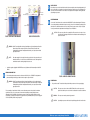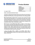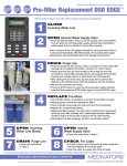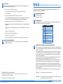
1
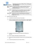
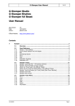
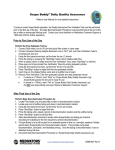
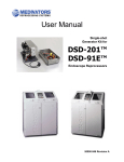
8
FINAL TESTS
Three full cycles must be completed without an alarm.
•
Install high-level disinfectant Part A and Part B containers as described in User manual.
•
Press the START button.
•
Check the flow through the tubing during the disinfect, air, and rinse cycle.
•
Check if incoming water pressure regulator provides a flow rate of 3.2GPM. (12 liters/min.) at a pressure
of 35-40 PSI (2.4-2.75 BAR). Adjust the External Water Regulator during the Flush Cycle.
•
Adjust the internal regulators to 18-20 PSI (1.25-1.38 BAR) during the Flush Cycle.
•
Verify the unit is level. Watch the rear basin overflow during the HLD cycle. Disinfectant should not flow
over this drain.
−
9
SITE REQUIREMENTS AND INSTALLATION
To be sure that the system is ready to operate, perform a trial run with water as outlined below. Use the
Restrictor Hook-up to simulate an endoscope.
Following these instructions accurately and completely will provide consistent and correct
installation procedure for the DSD EDGE.
1
APPLICABLE DOCUMENTS
2
INSTALLATION KIT
●
DSD Edge User Manual
●
DSD Edge Service Manual
The DSD Edge reprocessor is provided with an installation kit to adapt the unit to building supplies. The
following items, included in the kit, are used during installation.
Item
If fluid escapes over the drain during the HLD cycle the unit is not level. Adjust the screw pads and
re-test.
•
Verify the cycle completes with no errors.
•
Verify there is no fluid on the floating lid after a cycle.
•
Verify there are no leaks in the reprocessor.
•
Perform a water line disinfection procedure using the restrictors as described in the user manual.
DSD EDGE
INSTALLATION VERIFICATION
The Installation Verification form is used to document that the reprocessor has been properly installed,
tested and is ready for operation.
3
Description
1
3/8” Water Regulator
2
Pressure Gauge
3
3/8” plug
4
Pre-filtration system
5
1 micron filter
6
0.45 micron filter
7
Filter wrench
8
1 inch drain hose
9
1 inch drain elbow
10
Pre-filter installation hose kit
WATER SUPPLY (POTABLE) AND PRE-FILTERS OVERVIEW
• Below is an overview of the water supply and pre-filtration system connections. For detailed instructions,
please refer to the instructions included in the pre-filtration system. Dimensions of the water pre-filtration
system are shown in Figure 1.
• An incoming water shut-off valve must be installed upstream of the pre-filter system. The valve must be
easily accessible to the user to shut off the water supply when not in use. Ensure the incoming water
pressure provides a flow rate of 3.2 gal/min (12 liters/min) at a minimum pressure of 40 PSI (2.75 BAR),
but not more than 90 PSI (6.2 BAR).
• A customer supplied water temperature mixing valve must be installed before the pre-filter system. The
mixing valve must be able to maintain a water temperature of 95°F ± 4°F, (35°C ± 2°C).
• Install the incoming water pre-filter, supplied with the reprocessor. The user must have an easy access to
the filters. There should be enough room below the filter assembly to be able to change the filters.
• Install the external water regulator between the outlet of the pre-filter assembly and the DSD EDGE.
• Attach one end of the stainless steel water hose to the regulator. Attach other end to the water inlet of the
DSD EDGE. The installation kit ships with hardware that should fit most installations. If not, the hardware
may be sourced locally.
• Mount the filter assembly on the wall where the filters can be easily changed and the gauge checked.
Medivators Website “Resource Center”
Go to: www.minntech.com/medivators, Select “Resource Center” and “User Library” for detailed user guides and hook-up
matrices, report forms and logs, and product bulletins
Medivators Customer and Technical Support:1-800-444-4729
✍
✍
NOTE:
Use 1/2-inch piping for all water line plumbing.
NOTE:
This unit is piped and assembled as shown with the outlet on the right side and gauge
#1 (incoming water pressure) on the left (figure 1).
Endoscope reprocessing the way it should be
© MINNTECH CORPORATION All rights reserved. 50097-091/A
MEDIVATORS
Gauge #1 Gauge #2 Water Outlet
To DSD Edge
Water Inlet:
From main water supply
✍
✍
•
4
DSD-201 DSD-201 Installation and testing Instructions
Unit set-up
Move the reprocessor to the installation location before removing the protective packaging material. If
this is not possible, use a hand truck or moving dolly and ensure the reprocessor is not damaged. The
reprocessor must be installed on a level surface or be adjusted to level. Adjust the leveling pads after
unpacking 6.
the reprocessor.
System Drain
Connect the 1” drain elbow to the rear drain of the DSD-201. The elbow threads
require Teflon tape.
Housing 1
Contains 1 micron filter
FIGURE 1. FILTRATION SYSTEM DIMENSIONS
5
Gauge #3
Housing 2
Contains 0.45 micron filter
6
SYSTEM DRAIN
Connect the drain tube provided with the reprocessor (36 inches of 1-inch diameter
Connect the 1” drain
elbow
to the
the DSD
require of
Teflon
clear
tubing)
torear
the drain
drain of
elbow.
TheEdge.
drain The
tubeelbow
must threads
have 3 inches
droptape.
(7.5 cm)
greater
overwith
thethe
36-inch
length.(36
Consult
maintenance
Connect the drain or
tube
provided
reprocessor
inchesyour
of 1-inch
diameter department
clear tubing)for
to the
multiple
installation.
drain elbow. The drain
tube reprocessor
must have 3 inches
of drop (7.5cm) or greater over the 36” (91cm) length.
Consult your maintenance department for multiple reprocessor installation.
✍
FIGURE 2. FILTRATION SYSTEM
Caution: The reprocessor drain relies on gravity flow. There must be no low
CAUTION: The reprocessor drain relies on gravity flow. There must be no low spots or loops
spots or loops in the drain line. Fluid trapped in the drain line will
in the drain line. Fluid trapped in the drain line will interfere with free drainage and
interfere with free drainage and reprocessor function.
reprocessor function.
WARNING: DO NOT over-tighten filter housings (hand-tighten only). Over tightening will result in
failure of the pre-filter components, which can lead to flooding or water leaks.
Plumbing fittings should be hand tightened followed by one complete turn with the
appropriate wrench.
NOTE:
If the water supply line is brought in from the opposite side of the system inlet, run it
behind the machine close to the floor so that the disinfector can be flush against the
wall with the water line running through the base recess.
Install the regulator (supplied in DSD Edge accessory kit) between the filter assembly and the DSD
Edge.
REGULATOR SET-UP
• The external regulator water pressure is set between 35-40 PSI (2.40 – 2.75 BAR). This adjustment is
performed during the flushing cycle after the unit is ready for cycle verification.
✍
WARNING: DO NOT over-tighten water filter housings (hand-tighten only). Over tightening will
result in failure of the pre-filter components, which can lead to flooding or water leaks.
Plumbing fittings should be hand tightened followed by one complete turn with the
appropriate wrench.
The accumulation of particulates in a filter can cause the water pressure to drop below the minimum
required level. This can occur every two to three months, depending on water quality. A pressure
differential of 5 PSI (0.35 BAR) or greater between gauges on each side of a filter indicates a need for
replacement. For example, if the pressure on gauge #2 is 35 PSI (2.41 BAR) when the pressure on gauge #1
is 40 PSI (2.75 BAR), a filter change is required.
figure 3. Sample of a drain installation
7
ELECTRICAL
•
Plug cord into outlet. The outlet should be placed within operators reach for easy unplugging.
✍
✍
✍
CAUTION:
The reprocessor does not have an ON/OFF switch. Be sure the reprocessor is
7.
Electrical
positioned so that the power cord or main circuit breaker is accessible at all times.
Caution: The reprocessor does not have an on/off switch. Be sure the
reprocessor is positioned so that the power cord or main circuit breaker
WARNING: The reprocessor
must beat
protectively
is accessible
all times. grounded.
CAUTION:
Operating the reprocessor without a hook-up fitting may blow the slow blow fuse.
Document Number MI02-0160 Revision D
Endoscope reprocessing the way it should be
Page 4 of 5
MEDIVATORS
8
FINAL TESTS
Three full cycles must be completed without an alarm.
•
Install high-level disinfectant Part A and Part B containers as described in User manual.
•
Press the START button.
•
Check the flow through the tubing during the disinfect, air, and rinse cycle.
•
Check if incoming water pressure regulator provides a flow rate of 3.2GPM. (12 liters/min.) at a pressure
of 35-40 PSI (2.4-2.75 BAR). Adjust the External Water Regulator during the Flush Cycle.
•
Adjust the internal regulators to 18-20 PSI (1.25-1.38 BAR) during the Flush Cycle.
•
Verify the unit is level. Watch the rear basin overflow during the HLD cycle. Disinfectant should not flow
over this drain.
−
9
SITE REQUIREMENTS AND INSTALLATION
To be sure that the system is ready to operate, perform a trial run with water as outlined below. Use the
Restrictor Hook-up to simulate an endoscope.
Following these instructions accurately and completely will provide consistent and correct
installation procedure for the DSD EDGE.
1
APPLICABLE DOCUMENTS
2
INSTALLATION KIT
●
DSD Edge User Manual
●
DSD Edge Service Manual
The DSD Edge reprocessor is provided with an installation kit to adapt the unit to building supplies. The
following items, included in the kit, are used during installation.
Item
If fluid escapes over the drain during the HLD cycle the unit is not level. Adjust the screw pads and
re-test.
•
Verify the cycle completes with no errors.
•
Verify there is no fluid on the floating lid after a cycle.
•
Verify there are no leaks in the reprocessor.
•
Perform a water line disinfection procedure using the restrictors as described in the user manual.
DSD EDGE
INSTALLATION VERIFICATION
The Installation Verification form is used to document that the reprocessor has been properly installed,
tested and is ready for operation.
3
Description
1
3/8” Water Regulator
2
Pressure Gauge
3
3/8” plug
4
Pre-filtration system
5
1 micron filter
6
0.45 micron filter
7
Filter wrench
8
1 inch drain hose
9
1 inch drain elbow
10
Pre-filter installation hose kit
WATER SUPPLY (POTABLE) AND PRE-FILTERS OVERVIEW
• Below is an overview of the water supply and pre-filtration system connections. For detailed instructions,
please refer to the instructions included in the pre-filtration system. Dimensions of the water pre-filtration
system are shown in Figure 1.
• An incoming water shut-off valve must be installed upstream of the pre-filter system. The valve must be
easily accessible to the user to shut off the water supply when not in use. Ensure the incoming water
pressure provides a flow rate of 3.2 gal/min (12 liters/min) at a minimum pressure of 40 PSI (2.75 BAR),
but not more than 90 PSI (6.2 BAR).
• A customer supplied water temperature mixing valve must be installed before the pre-filter system. The
mixing valve must be able to maintain a water temperature of 95°F ± 4°F, (35°C ± 2°C).
• Install the incoming water pre-filter, supplied with the reprocessor. The user must have an easy access to
the filters. There should be enough room below the filter assembly to be able to change the filters.
• Install the external water regulator between the outlet of the pre-filter assembly and the DSD EDGE.
• Attach one end of the stainless steel water hose to the regulator. Attach other end to the water inlet of the
DSD EDGE. The installation kit ships with hardware that should fit most installations. If not, the hardware
may be sourced locally.
• Mount the filter assembly on the wall where the filters can be easily changed and the gauge checked.
Medivators Website “Resource Center”
Go to: www.minntech.com/medivators, Select “Resource Center” and “User Library” for detailed user guides and hook-up
matrices, report forms and logs, and product bulletins
Medivators Customer and Technical Support:1-800-444-4729
✍
✍
NOTE:
Use 1/2-inch piping for all water line plumbing.
NOTE:
This unit is piped and assembled as shown with the outlet on the right side and gauge
#1 (incoming water pressure) on the left (figure 1).
Endoscope reprocessing the way it should be
© MINNTECH CORPORATION All rights reserved. 50097-091/A
MEDIVATORS