1
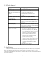
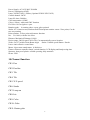
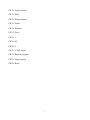
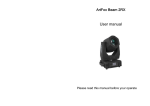
User manual Spot 15R Beam/Spot/Wash 3-in-1 Moving Head Light Please read this manual before your operate 1 Content 1. Installation of computer light. 2. Installation of lamp. 3. Power supply. 4. Connection of control signal line. 5. Corrective maintenance. 6. Cleanly maintenance 7. Warning. 8. Difficulty disposal. 9. Qualification. 10. Channel function Notice: because the policy of improve the products quality of our company. Maybe some data in the instructions will change in future. By that time, we won’t inform you about the changed matters. Marten company reserve the right of changing correlative specification when improve the products. Publisher of the instruction will not responsible for veracity of information and some correlative results caused by this information. 2 1. Installation of computer light. Using eight M10 size bolts, through making use of bracket that owned by computer light install. Make sure the firmness of installation, in case swing or glide happen when it works. Each weight of computer light is 20.5KG more or less. Before installation, it should be ensure if frame can support the weight. For safety, a safe chain should be through the side handle of lighting body. Notice: please don’t use the die down yoke of computer light to rise, to lower, and move it. 2. Installation of lamp. loosen plastic body which locate in luffing structure of computer lighting body, and strengthen screw of right-and-left cover shell, then open the cover forth gently, at the tail of shine lamp, screw off four coppery screw and move metallic gobo flag and heat guard of two sides, then can replace lamp. When install it, please use HMI575W modulator tube. Pay attention to screw down the screw of two sides of lamp, or it cause high voltage short circuit and discharge for poor contact. It influence service life of lamp, and damage components of circuit board. After finish it, please strengthen the metallic gobo flag and heat guard of two sides of lamp firstly. Then using adhesive tape to fold covering shell, and strengthen screws of right-and-left of it. MSD light products are provided with high voltage modulator tube what has exterior igniter. When operate these modulator tubes, it must be careful, and should read the instruction of modulator tube that offer by manufacturer before operation. Warning 1: Don’t forget install metallic gobo flag and heat guard that beside the lamp or thermal radiation is easy to bake the plastic shell distortion. Seriously, it will raise fire alarm. Manufacturer will not responsible for these losses. Warning 2: Modulator tube will reach to a high temperature when it works, and the trait of gas discharge lamp can not intermittent power supply. It must cool at least 15 minutes to work again after power supply cut off, or it will induce high pressure discharge, short circuit, and even burn out parts of computer control panel. 3. Power supply. Using appropriative plug connect computer light and power main lead. Pay 3 attention to consistent of voltage, frequency and supply source of backboard of computer light. Suggest each computer light to use a separate power supply, so each light can be turn on and turn off at will. L=Brown E=Yellow/Green N=Blue Important matters: Each computer light should be earthed and whole electro assembling must accord with standard demand. The power consumption of computer light is 680VA. Monitoring restoration system: After computer light switch on power, circuitry will be install. This function makes lamp cobra moving to a limiting position, and it will turn interior color and superimposed wheel of pattern. Thus the control system of microprocessor can login all place of electrical machines which controlled by it. It will bring electric noise in computer interior, when modulator tube damage or burnout. Maybe it will disturb normal operation of MPU. computer light has an electronic monitoring system that can watch operation of MPU, and ensure that will start up reinstallation function when it is disturbed. After it finish, computer light can accept new control instruction and operate without a hitch. 4. Connection of control communication wire Connection of controller and computer light or connection between each computer light should use two-core shielded cable, and diameter of each core should be o.5MM at least. When it joined in or come out, it should be used cylindrical three-legged XLR plug and outlet which supplied along with computer light. Connection of XLR can refer to the list below. Attention: every line should not touch each other or touch plug. computer light can accept data control signal of DMX512 (1990) format. Control signal connect with panel which earmarked “DIGITAL IN”, then connect socket which earmarked “DIGITAL THRU” with socket of next computer light which earmarked “DIGITAL IN”. After receive signal of DMX512, the status lamps close to switch of address code will fulgurate. Or it will extinguish. If it always in shine, it means DMX signal is false. 4 DIGITAL THRU 3 ︱ ∕\ 1 2 DIGITAL IN 3 ︱ ∕\ 2 1 DMX512 PIN FUNCTION 1 GND 2 DATA3 DATA+ Suggest to use DMX signal terminal, it can avoid the breakage of data control signal. Cause by electric noise. In simple terms, DMX terminal is a XLR linker in which has a 120Ω resistance between two-legged and three-legged plug. And the resistance should be connected with “DIGITAL THRU” socket of the last computer light of computer light chain. The connection can refer to table below. 120 3 ∕\ 2 1 ︱ The connection of DMX terminal connect a 120Ω resistance between two-legged and three-legged of XLR plug, and connect it to DIGITAL THRU socket of the last computer light of computer light chain. 5. Corrective maintenance If lens of computer light be damaged or broken, please replace a new one, and the same to modulator tube. If light turn dark, it means service life of modulator tube is up, should be replaced in time. The old modulator tube can explode. When computer light works out of order, fuse in back panel should be checked. Notice: If it need replace, using same spec fuse that earmarked in back panel. In the computer light, circuit board has a 3AT fuse. If the fuse has blown, it need replaced by professional. Computer light also have two heat protectors, they should cut off power supply when the temperature is too high. If it happened, fan should be checked whether there is a barrage or not. If fan is dirty, please switch on the power supply after clean it. Examine operation of fans, if it doesn’t work, please mend it by professional. 6. Cleanly maintenance In order to computer light operate steadily, it should keep clean. Suggest clean 5 lighting body and fan every 15 days. Lens and dichroic filter should be cleaned at stated time to assure the best light effect. Don’t use any deliquescent cleaner to clean dichroic filter. 7. Warning Don’t dismounting or refit computer light. Don’t touch water and other kind of liquid and metal substance (IP20). Don’t install in a high wettest condition. Don’t illuminate on tinderbox, computer light must keep 5M away from tinderbox. Computer light should keep 0.5M away the surface of adjacent object. Don’t look beam in the face, or it may injure your eyes. Notice: modulator tube will reach to a high temperature when it works. It must be completely cool at least 15 minutes before operate again. 6 8. Difficulty disposal Problem Computer light can’t start. Though it shine, computer light don’t accept dictate of control. Computer light works only in intermittence. Shadow has halo. Beam looks gray. Lamp is not bright. The way to solve Check fuse of back-panel. Check data startup address (see section 5), and check connection of communication control line (see section 4). Check fan, if it operate normally. Check the number of electro-focus channels if it suit current range of the projection. Maybe service life of modulator tube is over, it must be replaced. Check optical component if it is clean. 1. Because of improper operation, lamp not completely cool. The fan in the lighting body must be cool 10 minutes, cut off power supply at least 5 minutes, makes internal inductor renew completely, then switch on power supply. 2. Check if service life of lamp is over. 3. Check lamp and trigger line if it is creepage, desquamation or poor contact. 4. Replace a new trigger. 9. Qualification The list of control display panel designed specially for many types of computer light, and equipped multifunctional control mode, it is simple to control. A few functions not equipped in some types of computer light, and the corresponding option of list set inefficacy. 7 Power Supply: AC110V-240V 50/60Hz Power Consumption: 450W Lamp: YODN 330W, 1,500hrs, (Optional YODN 15R 330 W) Control channel: 24CH Lamp life time; 2000 hrs Color temperature: 8500K Color: 6 colors+ white and CMY function Fix Gobo: 14 fixed gobos+ open Rotation gobo: 8 rotation gobos+ open, gobo optional Strobe: 0-13 times/second, random strobe Prism/prism rotation: rotate 3 face prism, Can be two-way rotating Prism rotation: 16 face prism with macro function Iris: 5%-100%, with the iris effect. Dimmer: Mechanical Dimmer 0-100% Project range: 540°for pan,270°for Tilt, Can automatically correct location Zoom: 9°to 27°ariable Zoom Beam Angle Strobe: Variable speed Shutter / Strobe Lense: Anti-reflective coated lense Motor: 16pcs mute sound motor, 16 bit driver. Fixtures: Remote controller lamps’ switch function, LCD display and lamp's using time Structure: heat-proof plastic+ module pressing alloy materials IP rate: IP20 10. Channel function CH1: Pan CH2: Pan fine CH3: Tilt CH4: Tilt CH5: X/Y speed CH6: Strobe CH7: Lamp on CH8: Iris CH9: Color CH10: Gobo CH11: Rotate gobo 8 CH12: Gobo rotation CH13: Price CH14: Prism rotation CH15: Zoom CH16: Dimmer CH17: Frost CH18: C CH19: M CH20: Y CH21: C/M/Y speed CH22: Built in program CH23: Lamp control CH24: Reset 9