1
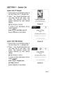
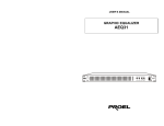
MANUALE UTENTE –USER’S MANUAL
STARPOINT 1200
PLIS1200CN
Rev. 07/2006
INDICE
INTRODUZIONE ................................................................................................................................................3
SPECIFICHE TECNICHE...................................................................................................................................3
FUNZIONI...........................................................................................................................................................3
INSTALLAZIONE................................................................................................................................................3
CONSIGLI PER L’USO.......................................................................................................................................3
MANUTENZIONE ...............................................................................................................................................4
RISOLUZIONE PROBLEMI................................................................................................................................4
UTILIZZO DELLA CONSOLE COMANDI...........................................................................................................4
SCHEMA DELLA CONSOLE DI COMANDO.....................................................................................................5
2
INTRODUZIONE
Grazie per aver scelto lo STARPOINT 1200CN. Se è la prima volta che si utilizza l’apparecchio, leggere e seguire attentamente le
istruzioni riportate su questo manuale.
SPECIFICHE TECNICHE
Alimentazione:
230 V 50 Hz o a richiesta 120 V 60Hz
Lampada:
HMI1200GS Osram
Codice:
PLLPHMI1200GS
Controllo:
DMX 512
Numero di canali:
4
Dimensioni:
(1055x460x320) mm
Dimensioni console:
(395x325x235) cm
Peso:
40 Kg
Iris:
10-100%
Effetti:
Effetto strobo regolabile da 1 a 7 flash al secondo, effetto rainbow con velocità regolabile,
Protezione:
IP20
effetto dimmer 0-100%. Blackout.
FUNZIONI
•
Conforme agli standard di sicurezza, livello di protezione IP 20.
•
Sistema di cambio colori veloce, preciso, stabile e silenzioso.
•
Circuito di protezione contro il surriscaldamento e la sovracorrente.
•
Raffreddamento ad aria tramite tre ventole di raffreddamento.
•
Effetto Rainbow.
INSTALLAZIONE
Alimentazione
Assicurarsi che il tipo di alimentazione sia compatibile con le specifiche tecniche dell’apparecchio onde evitare seri danneggiamenti
sia alla rete che al proiettore.
Installazione e rimozione della lampada
Prima di procedere, assicurarsi che l’apparecchio sia sconnesso dall’alimentazione e che la lampada si sia raffreddata
completamente.
Svitare le due viti a lato del portalampada e inserire la lampada con cautela facendo attenzione a non toccarne il bulbo. Una volta
posizionata la lampada riavvitare le viti.
Connessioni
Accertarsi che l’apparecchio sia collegato a terra.
CONSIGLI PER L’USO
Accensione / spegnimento
Le lampade a scarica (HMI575W e HMI1200W) non sono adatte ad un uso intervallato da accensioni e spegnimento. Ogni volta che
l’apparecchio viene spento, la lampada deve poter raffreddarsi per almeno 20 minuti prima che sia possibile riaccenderla, altrimenti
potrebbero presentarsi, con il lungo andare, problemi alla lampada e sul circuito elettronico.
3
Messa in funzione di più proiettori.
Accendere il proiettore prima di accendere la console dei comandi. I proiettori collegati sulla stessa linea andrebbero accesi uno alla
volta per evitare che si creino ogni tipo di interferenze tra loro.
Pericolo di incendio.
Materiali infiammabili come carta devono essere tenuti lontano dall’’apparecchio ed evitare di ostruire le aperture delle ventole di
raffreddamento.
MANUTENZIONE
Pulire con regolarità l’apparecchio, le lenti e la console dei comandi.
Controllare il serraggio di viti e dadi regolarmente.
Utilizzare sempre lampade che rispondano alle specifiche del prodotto.
RISOLUZIONE PROBLEMI
La lampada non si accende
•
Controllare che il fusibile non sia interrotto e accertarsi che l’alimentazione sia di 230 V in AC.
•
La lampada non si è raffreddata sufficientemente. Lasciare che si raffreddi.
•
La lampada si è spenta a causa di un surriscaldamento interno dell’apparecchio. Controllare che le prese esterne e i condotti
interni di areazione non siano otturati.
•
Assicurarsi che la lampada non si sia danneggiata o che risponda alle specifiche tecniche dell’apparecchio.
•
Controllare l’accenditore. Verificare la solidità dei contatti e del cablaggio elettronico dell’accenditore.
•
Controllare che il ballast non sia danneggiato.
I motori non funzionano correttamente
•
Controllare che il fusibile non sia interrotto e accertarsi che l’alimentazione sia di 230 V in AC.
•
Controllare se i cavi di rete o i connettori si siano rovinati o staccati.
•
Controllare se le viti per il serraggio della flangia del motori si siano allentate o se vi sono corpi estranei all’interno.
•
Verificare che le prese o gli elementi del circuito integrato siano ben fissati e che non abbiano preso colpi.
Problemi di comunicazione tra proiettore e console
•
Assicurarsi della corretta connessione dei cavi e che essi siano ben saldati ai rispettivi connettori.
•
Controllare di aver eseguito un corretto indirizzamento.
•
Assicurarsi che il circuito integrato non si sia rovinato a causa di una sovratensione.
•
Possibilità di un indebolimento del segnale a causa di una eccessiva lunghezza del cavo di comunicazione. Nell’eventualità,
aggiungere un amplificatore di segnale alla linea di comunicazione e un terminale da 120 ohm nel connettore dell’ultimo
proiettore.
•
Controllare che non ci siano segnali o campi elettromagnetici che possano interferire con l’apparecchio.
•
Verificare il corretto funzionamento o la compatibilità della centralina di controllo esterna.
UTILIZZO DELLA CONSOLE COMANDI
Prima di tutto assicurarsi che la console di serie sia ben fissata alla parte posteriore del proiettore e che le prese di alimentazione e di
comunicazione siano ben collegate. Se si sceglie di adoperare una centralina DMX 512 esterna, scollegare la presa di
comunicazione della console fornita di serie.
INDIRIZZAMENTO
Il proiettore ha 4 canali quindi se si vuole collegare uno o più proiettori ad una centralina va fatto l’indirizzamento come segue:
Proiettore 1 avrà Indirizzo 1 quindi Codice indirizzo (1=ON)
Proiettore 2 avrà Indirizzo 5 quindi Codice indirizzo (1,3=ON)
Proiettore 3 avrà Indirizzo 9 quindi Codice indirizzo (1,4=ON)
Proiettore 4 avrà Indirizzo 13 quindi Codice indirizzo (1,3,4=ON)
Proiettore 5 avrà Indirizzo 17 quindi Codice indirizzo (1,5=ON)
Proiettore 6 avrà Indirizzo 21 quindi Codice indirizzo (1,3,5=ON)
…
4
SCHEMA DELLA CONSOLE DI COMANDO
A:
Quando il pulsante I si trova nella posizione 0 (FIXED COLOURS) gli 8 bottoni permettono di attivare i rispettivi otto colori.
B:
Interruttori che permettono di selezionare la dimensione massima e minima dell’apertura.
C:
Interruttori per la funzione di shutter.
D:
Slider con funzione dimmer (quando il selettore G è su 1) oppure regolatore della velocità della strobo (quando il selettore G è
su 0).
E:
Slider per la regolazione della dimensione dell’apertura.
F:
Slider che regola la velocità della rotazione dei colori quando il selettore I si trova in posizione 1 (RAINBOW).
G:
Selettore della funzione dimmer (posizione 1) e funzione strobo (posizione 0).
H:
Selettore del filtro temperatura colore (3200K, 5600K, 6000K).
I:
Interruttore per attivare la funzione RAINBOW (su posizione 1) o per la scelta degli 8 colori prefissati dai relativi tasti A.
J:
Spia del colore attivo.
5
INDICE
TECHNICAL SPECIFICATION...........................................................................................................................7
FUNCTIONS.......................................................................................................................................................7
INSTALLATION ..................................................................................................................................................7
ATTENTIONS FOR USE ....................................................................................................................................7
MAINTENANCE..................................................................................................................................................8
TROUBLE SHOOTING.......................................................................................................................................8
CONTROL PANEL INFO....................................................................................................................................8
PANEL SKETCH MAP OF THE BUTTON .........................................................................................................9
6
WELCOME
Thank you for choosing the Follow Spot STAPPOINT 1200CN. Prior to use, we suggest you to read carefully the instructions.
TECHNICAL SPECIFICATION
Power supply:
230 V 50 Hz or 120 V 60Hz on request
Lamp:
HMI1200GS Osram
Code:
PLLPHMI1200GS
Control signal:
DMX 512
Number of channels: 4
Dimensions:
(1055x460x320) mm
Control handle:
(395x325x235) cm
Weight:
40 Kg
Iris:
10-100%
Effects:
Strobe effect with adjustable speed (1-7 flashes/sec). Dimmer effect (0-100%). Blackout.
Housing Protection:
IP20
FUNCTIONS
•
Safety standard compatible, IP 20 protection level.
•
Quick, accurate, stable and noiseless color switching system, free of the problems in mechanical color switch.
•
Embedded with overheat protection and high voltage line protection.
•
3 Axles flow fans for cooling optimised internal air duct design, sufficient heat emission.
•
Rainbow effects.
INSTALLATION
Power up
Make sure the power supply is sufficient for the power consumption of the lamps before power up. Otherwise the power lines and the
projectors might be damaged.
Installation and removal of lamps
Make sure the power is cut and the lamps are cooled before the operation. You just unscrew the 2 copper screws which on the sides
of the lamp, and replace the lamp slightly. No other parts need to be removed. When replacing the lamp, keep the fume cock upward
and do not touch the lamp globe. The lamp shall be firmly planted to avoid bad connection and damage to the circuit.
Communication connection
The insulation resistance of all the installation equipments and the electrical lines shall be up to the safety standard and the machine
crust shall be well grounded.
ATTENTIONS FOR USE
Power On/Off
The gas discharge lamps shall not be used in an on and off manner. Each time the lamps are turned off, the lamps shall be cooled for
at least 20 minutes before the lamps are turned on again. Otherwise, high voltage discharge short circuit or interference to periphery
equipment might arise.
7
Operation experience.
Power on the projectors before the controller. All the projectors in the same communication lines should be powered up in 5 – 10
seconds. Otherwise, the last powered projectors, during their startup, might affect the normal operation of the anterior projectors.
Fire warning.
Flammables materials are not allows to fall in the lamps or the air duct. Otherwise, the high temperature lamps in the lamps might
cause fire. In case of unusual smell or take fire, turn off the power immefdialtely and have the case properly handled fbefore turning
on the lamps again.
MAINTENANCE
Clean the machine, lens, machine interior and computer board regularly.
Fasten the screws and nuts in the hoisting parts and the racks regularly.
Replace lamps according to the actual situation. Do not use inferior quality lamps.
TROUBLE SHOOTING
The lamp does not work
•
Check whether the power supplied is 230 V AC and whether the fuse is burnout.
•
The lamp is not cool enough. Let it cooled down.
•
The lamp is in over heat protection status due high interior temperature. Check whether the fan and the air duct are blocked.
•
Inferior or aged lamp. Replace the lamp or add ignition coils to aid the ignition.
•
Igniter degradation or poor contact. Replace according to the original circuit.
•
Ballast damaged.
The motors do not work correctly
•
Check whether the power supplied is 230 V AC and whether the use is blown.
•
Check whether the motor lines or connecting lines are degraded or broken.
•
Check whether the small flange screws for mechanical fastening is loose, poor in contact, aged or blown.
•
Check whether the output voltage of the transformer is normal.
The communication is out of control
•
Wrong connection of communication lines, unwelded, loose or short the circuit.
•
Incorrect address code setting.
•
Communication IC on computer board broken under high voltage.
•
Signal attenuated over excessive long communication line. Add a serial signal amplifier to the communication line of 120 ohm
terminator of the last projector cannon connector.
•
Signal or voltage Interference from periphery equipments.
•
Control equipments damaged or incompatible signal.
CONTROL PANEL INFO
First, fir the control-handle device on both sides of the move light, and immobilize it, and insert the panel plug (power+signal) in the
corresponding socket of back plate of the light. Then it’s possible to operate the connecting machine communication. If you use outer
DMX 512 controller, you must pulled out plug at first.
Setting method
The Follow Spot PLIS 1200CN has 4 channels. So if you want to connect one or more projectors, you must respect the following
setting method:
Projector 1 will have got Address No. 1 and Address Code (1=ON)
Projector 2 will have got Address No. 5 and Address Code (1,3=ON)
Projector 3 will have got Address No. 9 and Address Code (1,4=ON)
Projector 4 will have got Address No. 13 and Address Code (1,3,4=ON)
Projector 5 will have got Address No. 17 and Address Code (1,5=ON)
Projector 6 will have got Address No. 21 and Address Code (1,3,5=ON)
…
8
PANEL SKETCH MAP OF THE BUTTON
A:
When the button is in FIXED COLOURS position, 8 colours are activated under the control of 8 round buttons.
B:
Aperture size switch (to change the aperture size to maximum and the minimum).
C:
Lens hood (door) to switch between shutting off and letting in light.
D:
Flash speed or light spot lightness adjustment potentiometer. Its function status is related to key G.
E:
Aperture (spot) size adjustment potentiometer.
F:
Color adjustment potentiometer. When key I is in position RAINBOW, the continuous color change and speed is subject to the
control of this potentiometer.
G:
H:
Flash status and light adjustment status switch.
Color temperature switch. When it is in a status other than 5600K, the two round color buttons of ORANGE and D.BLUE are
deactivated.
I:
Continuous color change speed adjustment / skip-over to the next color switch.
J:
Color change indicator.
9
Notes
10
11
PROEL S.p.A.
(World Headquarters – Factory)
Via alla Ruenia 37/43
64027 Sant’Omero (TE) – Italy
Tel. +39 0861 81241
Fax. +39 0861 887862
e-mail: [email protected]
www.proelgroup.com