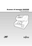
1
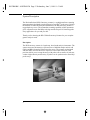
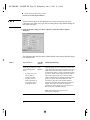
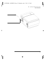
1BLTRM.BK : FRONT.FM Page i Wednesday, June 3, 1998 11:51 AM
Technical Support
Technical support for the HP GeneArray scanner is coordinated by Affymetrix, as
a component of the GeneChip system. Please read the Helpful Hints and
Troubleshooting Chapter prior to calling Affymetrix Technical Support.
Affymetrix Technical Support Telephone:
1-(888)-DNA-CHIP (362-2447)
Affymetrix Technical Support FAX:
408-481-0435
Affymetrix Technical Support e-mail:
[email protected]
Warranty Terms and Conditions
The GeneArray scanner is warranted to the end user by Affymetrix.
Please refer to the Affymetrix Terms and Conditions received with this instrument
at time of sale for information on the warranty.
Limited License
PROBE ARRAYS, INSTRUMENTS, SOFTWARE, AND REAGENTS ARE
LICENSED FOR RESEARCH USE ONLY. NO RIGHT TO MAKE, HAVE
MADE, OFFER TO SELL, SELL, OR IMPORT OLIGONUCLEOTIDE
PROBE ARRAYS OR ANY OTHER PRODUCT IN WHICH
AFFYMETRIX HAS PATENT RIGHTS IS CONVEYED BY THE SALE
OF PROBE ARRAYS, INSTRUMENTS, SOFTWARE, OR REAGENTS
HEREUNDER. THIS LIMITED LICENSE PERMITS ONLY THE USE OF
THE PARTICULAR PRODUCT(S) THAT THE USER HAS PURCHASED
FROM AFFYMETRIX.
1BLTRM.BK : FRONT.FM Page ii Wednesday, June 3, 1998 11:51 AM
ii
1BLTRM.BK : 1BLTRMTOC.fm Page iii Wednesday, June 3, 1998 11:51 AM
Contents
Table of Contents
Chapter 1
Introduction, 1
System Description, 2
Simple Scanning Procedure, 3
Safety Symbol Markings, 4
Manual Conventions, 5
Warnings and Cautions, 6
Regulatory Information, 7
General User Information, 8
Document Information, 10
Chapter 2
Operating the HP GeneArray Scanner, 11
Important Information to Consider Prior to Scanning, 13
Guidelines on Scanning GeneChip Probe Arrays, 14
Operating the HP G2500A GeneArray Scanner, 15
Analyzing the Data, 25
Aborting a Scan, 33
Turning Off the Laser and the Scanner, 34
GeneArray Scanner Options Button, 37
Filter Maintenance, 40
Replacing Scanner Fuses, 42
Chapter 3
Helpful Hints and Troubleshooting, 43
Technical Support, 45
Helpful Hints to Prevent Problems, 46
Most Common Solution to Problems, 49
Scanner Hardware Issues, 51
Software Alerts, 55
Problems with Scanned Images, 59
Grid Alignment Problems, 63
iii
1BLTRM.BK : 1BLTRMTOC.fm Page iv Wednesday, June 3, 1998 11:51 AM
Contents
Chapter 4
Specifications, 65
Product Description, 66
Specifications, 67
Dyes and Detection Specifications, 68
Power Module, 69
Chapter 5
Scanner Components, 71
Theory of Operation, 72
Product Description, 73
iv
1BLTRM.BK : 01INTRO.FM Page 1 Wednesday, June 3, 1998 11:51 AM
1
Simple Scanning Procedure, 3
Safety Symbol Markings, 4
Manual Conventions, 5
Warnings and Cautions, 6
Regulatory Information, 7
General User Information, 8
Document Information, 10
Introduction
1BLTRM.BK : 01INTRO.FM Page 2 Wednesday, June 3, 1998 11:51 AM
System Description
The Hewlett-Packard (HP) GeneArray scanner is a sophisticated laser scanning
instrument that is designed to read Affymetrix GeneChip® probe arrays. Built in
the tradition of other HP Analytical Instruments, the HP GeneArray scanner is
rugged and easy to use. The tremendous scanning capability of this instrument
gives Affymetrix more flexibility to design and develop novel GeneChip probe
array applications for you and your lab.
Thank you for choosing the HP G2500AGeneArray Scanner for your complex
genetic analysis needs.
Description
The HP GeneArray scanner is a bench-top, laser-based analysis instrument. The
scanner measures the intensity of fluorescence of labelled sample nucleic acid
(DNA and RNA) bound to GeneChip probe arrays. The scanner was designed
with the ability to focus the laser to a spot size of less than 4 microns. This
precision allows you to scan probe arrays with probe cells as small as 20 microns,
so that a higher density and diversity of probes can be synthesized on GeneChip
probe arrays.
2
1BLTRM.BK : 01INTRO.FM Page 3 Wednesday, June 3, 1998 11:51 AM
Introduction
Simple Scanning Procedure
Simple Scanning Procedure
• The HP GeneArray scanner automates all optical calibrations, laser settings
and GeneChip probe array alignment. A 4-step procedure is involved in
running a scan:
1. From the GeneChip software menu bar, choose Run, then choose Scanner.
2. Select the appropriate experiment name for the probe array to be scanned
and choose Start. A dialog box appears.
3. Load the GeneChip probe array into the loading port.
4. Click OK in the dialog box. A large format (1.28 cm X 1.28 cm) GeneChip
probe array can be scanned in about five minutes (single scan, single dye).
Smaller format probe arrays can be scanned in even less time.
• The HP GeneArray scanner reads each probe cell in the array and records
signal intensity data. The data is stored by the GeneChip software, and can be
analyzed at a later time.
3
1BLTRM.BK : 01INTRO.FM Page 4 Wednesday, June 3, 1998 11:51 AM
Introduction
Safety Symbol Markings
Safety Symbol Markings
4
Attention—consult users manual
AC power input
Secondary grounding
Power switch
On
Off
1BLTRM.BK : 01INTRO.FM Page 5 Wednesday, June 3, 1998 11:51 AM
Introduction
Manual Conventions
Manual Conventions
Warning
When you see a warning, it denotes a hazard. It calls attention to a procedure,
practice, or the like, which, if not correctly performed or adhered to, could result
in injury or death.
Caution
When you see a caution, it denotes a hazard. It calls attention to a procedure,
practice, or the like, which, if not correctly performed or adhered to, could result
in damage to or destruction of part or all of the product.
Software Conventions Used in this Manual
• GeneChip software operates under the Windows NT environment.
This manual assumes that the user is familiar with this environment.
• Most functions in the GeneChip software are mouse-driven.
• Selection of functions is accomplished through clicking the left mouse button
after positioning the cursor on the appropriate menu bar, tool bar (a set of
icons) or dialog box selections. This process is referred to in this manual as
“choose”. The term “click” will be used when a button icon is activated by
clicking the mouse, and when description of the physical action is required
for clarity.
• File names are shown with an asterisk denoting the particular file. A dot and
three capital letters denote the file extension, such as *.DAT.
• In the few instances where keystrokes are required, the name of the pertinent
key is show in capitals, such as ENTER.
5
1BLTRM.BK : 01INTRO.FM Page 6 Wednesday, June 3, 1998 11:51 AM
Introduction
Warnings and Cautions
Warnings and Cautions
•
!"# $ $ •
•
% $ % & '" ()
) * " •
+
•
•
( "+ % "
!"# $
%%&'
!"")!*"+*"")*,"-.
/"+0"12
0+3
4 '
!*"+*3"-.
/"+0"12
!0+5
6 ' */"-6/1 7 8
9 ('
•
•
,'
-.
• The Laser will not operate if the MAINS voltage is less than 106 volts. Contact
Affymetrix Technical Support for assistance.
• Avoid moving the scanner. Contact your Affymetrix Technical Support
Representative if you need to have the scanner moved, in order to avoid
misalignment or damage to the optics.
•
•
•
•
6
Class 1 Laser product per IEC825-1/EN60825-1
Laser product complies with 21CFR chapter 1, subpart J
Laser status indicator: Red=Power ON; Green=Ready
The laser tube must be disposed of according to applicable regulations
or returned to HP. The scanner laser plasma tube contains beryllium oxide,
which is a hazardous substance. The user does not have access to the laser
plasma tube during normal operation. Contact your Affymetrix Technical
Support Representative for assistance.
1BLTRM.BK : 01INTRO.FM Page 7 Wednesday, June 3, 1998 11:51 AM
Introduction
Regulatory Information
Regulatory Information
Acoustic Noise Information
Manufacturer’s
Declaration:
• English
This statement is provided to comply with the requirements of the German
Sound Emission Directive, from 18 January 1991. Sound Pressure Lp < 70
dB(A), at operator’s position, normal operation, according to EN 27779
(Type Test).
• Deutsch
Die folgende Information wird in Übereinstimmung mit den Anforderungen
der Maschinenlärminformationsverordnung vom 18. Januar 1991 erteilt.
Schalldruckpegel am Arbeisplatz bei normalem Betrieb, Lp < 70 dB(A), nach
EN 27779 (Typprüfung).
For Research Use Only
The HP GeneArray scanner is for RESEARCH USE ONLY, not for use in
diagnostic procedures.
7
1BLTRM.BK : 01INTRO.FM Page 8 Wednesday, June 3, 1998 11:51 AM
Introduction
General User Information
General User Information
Whom to Call?
• Affymetrix Technical Support:
Toll Free 888-DNA-CHIP [(888) 362-2447]
Scanner Identification
Each HP GeneArray scanner is identified by a unique 10-character serial number.
This serial number is located on a label on the lower right side of the front of the
instrument, as you face it.
When corresponding with Affymetrix about your instrument, be sure to include
the model number and the full 10-character serial number.
Write the serial number of your HP GeneArray Scanner here for reference:
Scanner Information
Serial #:
• HP GeneArray scanner serial number:
• HP GeneArray power module serial number:
• Installation Date:
• Service Warranty Expiration Date:
PC Information
•
Windows NT Log-on Password (update if changed):
Password =
8
1BLTRM.BK : 01INTRO.FM Page 9 Wednesday, June 3, 1998 11:51 AM
Introduction
General User Information
PC Drive Designators
PC Drive Designator (fill - in):
Hard Drive, CD, Floppy, Zip etc.
9
1BLTRM.BK : 01INTRO.FM Page 10 Wednesday, June 3, 1998 11:51 AM
Introduction
Document Information
Document Information
Disclaimer
• The information contained in this document is subject to change
without notice.
• Hewlett-Packard makes no warranty of any kind with regard to this material,
including, but not limited to, the implied warranties of merchantability and
fitness for a particular purpose.
• Hewlett-Packard shall not be liable for errors contained herein or for incidental
or consequential damages in connection with the furnishing, performance or
use of this material.
• Hewlett-Packard assumes no responsibility for the use or reliability of its
software on equipment that is not furnished by Hewlett-Packard.
• All products sold by Affymetrix are subject to the terms and conditions of the
applicable Affymetrix sales agreement.
Publication number
G2500-90005
First edition, 6/97
Printed in USA
© Copyright 1997
Hewlett-Packard Company
All Rights Reserved.
Reproduction, adaptation, or translation without prior written permission is
prohibited, except as allowed under the copyright laws.
*
Affymetrix®
Affymetrix® is a U.S. registered trademark used by Affymetrix, Inc.
* is a U.S. registered trademark used by Affymetrix, Inc.
GeneChip® is a U.S. registered trademark used by Affymetrix, Inc.
Microsoft® is a U.S. registered trademark of Microsoft Corporation.
Microsoft Windows NT 4.0® is a registered trademark of Microsoft Corporation.
10
1BLTRM.BK : 02OPER.FM Page 11 Wednesday, June 3, 1998 11:51 AM
2
Important Information to Consider Prior to Scanning, 13
Guidelines on Scanning GeneChip Probe Arrays, 14
Operating the HP G2500A GeneArray Scanner, 15
Analyzing the Data, 25
Aborting a Scan, 33
Turning Off the Laser and the Scanner, 34
GeneArray Scanner Options Button, 37
Filter Maintenance, 40
Operating the HP GeneArray Scanner
1BLTRM.BK : 02OPER.FM Page 12 Wednesday, June 3, 1998 11:51 AM
This chapter covers important information you will need to incorporate into
your laboratory testing Standard Operating Procedures. Highlights include:
• File Management: A necessary step prior to setting up GeneChip assay
experiment files.
• The need to visually inspect hybridized GeneChip probe arrays.
• How to operate the HP GeneArray scanner.
12
1BLTRM.BK : 02OPER.FM Page 13 Wednesday, June 3, 1998 11:51 AM
Operating the HP GeneArray Scanner
Important Information to Consider Prior to Scanning
Important Information to Consider Prior to Scanning
Large data files are generated from scanning a GeneChip probe array (each
experiment file can generate up to 50 megabytes of data). Therefore, it is
important to assure adequate data storage capability before scanning a batch
of probe arrays.
'
For advice in determining the best data storage configuration for your system,
contact Affymetrix Technical Support.
Visual Inspection of GeneChip probe arrays prior to scanning:
Always inspect your probe arrays for:
1 Air Bubbles.
2 Scratches.
3 Smudges/Fingerprints.
4 Condensation/Fog.
'
See the “Helpful Hints to Prevent Problems,” on page 46 for more information.
13
1BLTRM.BK : 02OPER.FM Page 14 Wednesday, June 3, 1998 11:51 AM
Operating the HP GeneArray Scanner
Guidelines on Scanning GeneChip Probe Arrays
Guidelines on Scanning GeneChip Probe Arrays
Time Restrictions
Please consult the appropriate Affymetrix GeneChip assay package insert for
further information.
Batching
Please consult with your Affymetrix Technical Support Representative if this is an
option for your particular GeneChip probe array applications.
Scanning Refrigerated GeneChip Probe Arrays
If you have stored your hybridized GeneChip probe arrays in the refrigerator, you
must allow them to come to room temperature, while protecting them from light.
Prior to initiating a scan, you must visually inspect each GeneChip probe array for
condensation. Scanning should not be initiated on a GeneChip probe array with
condensation on the array surface.
See Chapter 3, “Helpful Hints and Troubleshooting,” of this user’s guide for
more information.
Rescanning GeneChip Probe Arrays
The argon ion laser in the GeneArray scanner excites the fluorescently-labelled
and array-bound target nucleic acid, resulting in the emission of fluorescent light.
Upon excitation, the fluorescent molecules eventually bleach. They are then
irreversibly lost to the detection process. Thus, the next time the same array is
scanned, the labeled molecules will likely emit less light and the fluorescent
intensities will not be as high as those in the first scan. GeneChip probe arrays can
be rescanned, if necessary. The amount of bleaching that occurs is a function of
the dye. Storage conditions and length of storage can also affect the intensity upon
rescanning.
Please consult the appropriate Affymetrix GeneChip assay package insert for
further information.
14
1BLTRM.BK : 02OPER.FM Page 15 Wednesday, June 3, 1998 11:51 AM
Operating the HP GeneArray Scanner
Operating the HP G2500A GeneArray Scanner
Operating the HP G2500A GeneArray Scanner
The following sections will cover:
• Software Conventions Used in This User’s Guide
• Powering Up the GeneArray Scanner
• Starting a Scan from GeneChip Software
• Analyzing the Data
• Aborting a Scan
• Turning Off the Laser and the Scanner
• GeneArray Scanner Options Button
/0'
'
• Always turn the scanner on before entering the GeneChip software
• Then turn on the GeneChip workstation (if not already powered on) and
start the GeneChip software
Why?
Because the GeneArray scanner’s communication (SCSI) port needs to be on and
activated so that when the GeneChip software is started, the GeneArray scanner
can send a message via SCSI back to the GeneChip workstation and GeneChip
software. The GeneChip software needs to recognize that the GeneArray scanner
is turned on and ready to send and receive data and commands.
Failure to follow this procedure can lead to problems in communicating
with the scanner.
Software Conventions Used in this Manual
• GeneChip software operates under the Windows NT environment.
This manual assumes that the user is familiar with this environment.
• Most functions in the GeneChip software are mouse-driven.
• Selection of functions is accomplished through clicking the left mouse button
after positioning the cursor on the appropriate menu bar, tool bar (a set of
15
1BLTRM.BK : 02OPER.FM Page 16 Wednesday, June 3, 1998 11:51 AM
Operating the HP GeneArray Scanner
Operating the HP G2500A GeneArray Scanner
icons) or dialog box selections. This process is referred to in this manual as
“choose”. The term “click” will be used when a button icon is activated by
clicking the mouse, and when description of the physical action is required
for clarity.
• File names are shown with an asterisk denoting the particular file. A dot and
three capital letters denote the file extension, such as *.DAT.
• In the few instances where keystrokes are required, the name of the pertinent
key is show in capitals, such as ENTER.
16
1BLTRM.BK : 02OPER.FM Page 17 Wednesday, June 3, 1998 11:51 AM
Operating the HP GeneArray Scanner
Operating the HP G2500A GeneArray Scanner
Powering up the GeneArray scanner:
To power up the HP GeneArray scanner, depress the On/Off button found in the
lower left front corner of the GeneArray scanner.
Probe Array
On/Off Button
Scanner Status Lights
There are three LED scanner status lights on the right front of the scanner
(Green, Yellow, Red). If the power up is successful, the green and yellow lights
will first come on together. After the GeneChip software is started and the scanner
initializes and becomes ready, the yellow light will go off. The green light stays
on, to indicate that the scanner is ready to operate. If the red status light comes on,
indicating a serious failure, perform the “Power Cycling Procedure,” on page 49
in the “Most Common Solution to Problems,” and “Helpful Hints and
Troubleshooting,” in Chapter 3 of this user’s guide. If the red light continues
to stay on, call Affymetrix Technical Support.
17
1BLTRM.BK : 02OPER.FM Page 18 Wednesday, June 3, 1998 11:51 AM
Operating the HP GeneArray Scanner
Operating the HP G2500A GeneArray Scanner
Before You Start the Scanning Process
• Allow refrigerated GeneChip probe arrays to adjust to room temperature.
• Also, remember that the previously hybridized GeneChip probe arrays already
exist as experiment files in the computer. Do not re-enter the experiment
information.
• Just prior to scanning, make sure that no condensation is present on the
array surface.
'
Do not touch the glass surface of the probe array. Always remember to examine
the GeneChip probe arrays for scratches, air bubbles, condensation or fingerprints.
• Launch GeneChip software
GeneChip Icon
1 The GeneChip software needs to be running in order to start a scan on the
HP GeneArray scanner.
2 If you are not already in the software program, launch GeneChip software by
double-clicking on the GeneChip icon on the computer screen. If the GeneChip
software icon is not present, contact Affymetrix Technical Support.
18
1BLTRM.BK : 02OPER.FM Page 19 Wednesday, June 3, 1998 11:51 AM
Operating the HP GeneArray Scanner
Operating the HP G2500A GeneArray Scanner
Starting a Scan From GeneChip Software
Summary:
Once the scanning process is started from GeneChip software, the scanner
automatically loads the GeneChip probe array and focuses the laser onto it.
The data is collected line by line as the scan progresses and is displayed on the
computer screen. Once the scan is complete, the GeneChip probe array is
transported back to the loading port, and the intensity data is ready to be analyzed
in GeneChip software.
Starting a Scan:
1 Choose Run from the GeneChip menu bar, then choose Scanner.
You can also click on the Start Scan icon button located on the tool bar.
Start Scan Icon
The Scanner dialog box will appear on the computer screen.
'
The Options button in the Scanner dialog box brings up a special Scanner Options
feature. For many GeneChip probe array applications, it is unnecessary to choose
this function and the parameters should not be altered. See the description of this
feature at the end of this chapter. If you have any questions, contact Affymetrix
Technical Support, toll free at 1-(888)-362-2447.
19
1BLTRM.BK : 02OPER.FM Page 20 Wednesday, June 3, 1998 11:51 AM
Operating the HP GeneArray Scanner
Operating the HP G2500A GeneArray Scanner
2 In the Scanner dialog box, locate the Experiment Name drop down list on the left
side of the dialog box. Locate and highlight the experiment file name that represents
the GeneChip probe array that you want to scan. If the experiment name does not
appear here, look for it in the Previous Experiments box on the right side of the
dialog box. Double-click on the appropriate name, and it will appear in the
Experiment Name box.
3 If, by mistake you have chosen the wrong experiment name, simply go back
and choose the correct experiment name. It will replace the earlier entry.
Refer to the Affymetrix GeneChip software on-line help for details on establishing
experiment names.
4 Visually verify that the probe array type selected in the software and on the
GeneChip probe array label match. This step is critical to verify that you are
scanning the proper GeneChip probe array.
5 Click Start in the Scanner dialog box to begin the scan.
6 The GeneChip software will prompt you to load the GeneChip probe array into
the scanner.
7 Lift the door on the right front of the GeneArray scanner. Remove the previously
scanned GeneChip probe array, if applicable.
20
1BLTRM.BK : 02OPER.FM Page 21 Wednesday, June 3, 1998 11:51 AM
Operating the HP GeneArray Scanner
Operating the HP G2500A GeneArray Scanner
Probe Array
Scanner Door
Probe Array Loading Port
'
Do not force the GeneChip probe array into the loading port. Gently insert the
probe array until it is supported by the transport mechanism. The transport
mechanism will automatically move the GeneChip probe array into the
scanning area.
8 Load the desired GeneChip probe array into the scanner’s loading port.
9 Close the scanner door.
10 Click OK in the dialog box. The loading port door will make an audible “click”
as it locks.
11 The GeneArray scanner status bar will display all functions associated with the
GeneChip probe array scanning procedure.
21
1BLTRM.BK : 02OPER.FM Page 22 Wednesday, June 3, 1998 11:51 AM
Operating the HP GeneArray Scanner
Operating the HP G2500A GeneArray Scanner
Scanner Status
The scanner status bar is located in the bottom right-hand side of the GeneChip
software screen. During the scanning process, various status messages are
displayed which allow you to monitor the scanning process. Please become
familiar with this status bar, as it will aid in troubleshooting, in the unlikely event
that this might become necessary.
The following are messages displayed in the status bar, in the following order:
• Loading sample...
• Checking laser power...
• Autofocus: Homing...
• Autofocus: Measuring NE...
• Autofocus: Measuring SE...
• Autofocus: Measuring SW...
• Moving to focus position...
• Searching for chrome border...
• Scanning Chip (line by line status)
• Scan completed.
• Ejecting sample...
• Ready
22
1BLTRM.BK : 02OPER.FM Page 23 Wednesday, June 3, 1998 11:51 AM
Operating the HP GeneArray Scanner
Operating the HP G2500A GeneArray Scanner
The GeneChip probe array scanned image, stored in a *.DAT file, will appear
on the screen as the scan progresses.
Typical scanning time is about 5 minutes per single scan of a large format
(1.28 cm X 1.28 cm) GeneChip probe array, but will vary depending on the
particular GeneChip probe array application you are running.
A Completed Scan
• Once the scan is complete, the scanned GeneChip probe array will be
transported back into the loading port. The loading port door will unlock with
an audible “click.” The Scanner status box in the lower right-hand corner of
the GeneChip software screen will read Ready.
23
1BLTRM.BK : 02OPER.FM Page 24 Wednesday, June 3, 1998 11:51 AM
Operating the HP GeneArray Scanner
Operating the HP G2500A GeneArray Scanner
• At this point you can close this file by clicking the Close icon (X) in the upper
right corner of the image window. You can then continue scanning additional
GeneChip probe arrays. The scanned image data will be stored with the
experiment name as a data (*.DAT) file.
• The process of calling up this data file is discussed in “Analyzing the Data,”
on the next page.
• Remove the scanned GeneChip probe array.
'
If you need to rescan the GeneChip probe array, store it in a cool, dark place until
you are ready.
Please consult the appropriate Affymetrix GeneChip assay package insert for
further storage information.
24
1BLTRM.BK : 02OPER.FM Page 25 Wednesday, June 3, 1998 11:51 AM
Operating the HP GeneArray Scanner
Analyzing the Data
Analyzing the Data
Choosing the Data File to Analyze:
Once a scan has been successfully completed, a data file (*.DAT) will have been
created and stored in a folder by the GeneChip software. To complete the process
of analyzing a GeneChip probe array you can either:
• Analyze the *.DAT file once it is displayed on the computer screen
immediately upon completion of the scan
Or:
• Analyze previously saved files:
1 Choose File from the GeneChip software menu bar.
2 Choose the experiment data file you want to analyze, which will appear in the
following format: “experiment name.DAT”.
25
1BLTRM.BK : 02OPER.FM Page 26 Wednesday, June 3, 1998 11:51 AM
Operating the HP GeneArray Scanner
Analyzing the Data
3 If the experiment does not appear there, you must go to the File menu and choose
Open. Locate your *.DAT file from the directory in which you set up your
experiment file. Double-click on the experiment name.DAT file. The image will then
appear on the screen.
26
1BLTRM.BK : 02OPER.FM Page 27 Wednesday, June 3, 1998 11:51 AM
Operating the HP GeneArray Scanner
Analyzing the Data
Grid Alignment
Typically, the GeneChip software will overlay a grid (an array of white lines
delineating the probe cell boundaries) on the image displayed on your computer
screen. Occasionally, the following may happen:
No grid appears over the image in the *.DAT file.
1 Go to the GeneChip software menu bar and choose View.
2 The Grid selection should have a check mark next to it. If not, the grid display
function is disabled and will not show on the screen.
3 To enable the grid display function, click on the Grid selection once, so that a check
mark appears.
27
1BLTRM.BK : 02OPER.FM Page 28 Wednesday, June 3, 1998 11:51 AM
Operating the HP GeneArray Scanner
Analyzing the Data
Checking Grid Alignment
Before the analysis step can proceed, you must make sure that the grid is correctly
lined up on all 4 corners of the *.DAT file image as well as an arbitrarily chosen
spot in the center of the same *.DAT file image.
• Define the area in which to check alignment:
1 Position the mouse cursor at the upper left corner of the image, at a spot just outside
the “control oligo” checkerboard pattern.
2 Click on the mouse button and hold it down.
3 Drag the mouse down and to the right and stop at a spot just inside of the
checkerboard pattern.
4 Release the mouse button. By doing this you should have created a box around the
area you want to highlight.
28
1BLTRM.BK : 02OPER.FM Page 29 Wednesday, June 3, 1998 11:51 AM
Operating the HP GeneArray Scanner
Analyzing the Data
• Enlarge the defined area
5 Click the In button at the lower right-hand edge of the image screen. This will enlarge
the defined viewing area.
29
1BLTRM.BK : 02OPER.FM Page 30 Wednesday, June 3, 1998 11:51 AM
Operating the HP GeneArray Scanner
Analyzing the Data
6 Check to see if the grid is aligned around each of the probe cells. That is, the edges
and corners of each probe cell should correspond to the grid lines.
'
This figure illustrates a scanned image that is out of alignment with the grid.
The corner of the grid must be moved manually to align the grid boxes with the
checkerboard pattern.
7 Use the mouse cursor to locate the upper left hand corner of the grid. The cursor
will change to a double-headed arrow when placed on the corner of the grid.
8 Click the mouse button and hold it down while dragging the corner of the grid until
the uppermost probe cell on the outside edge of the grid aligns with the grid box just
below the corner grid box.
9 Once the grid is aligned sufficiently, choose the Out button at the lower right-hand
edge of the image screen. This will return the viewer to the normal view for
the image.
30
1BLTRM.BK : 02OPER.FM Page 31 Wednesday, June 3, 1998 11:51 AM
Operating the HP GeneArray Scanner
Analyzing the Data
Check all four corners of the GeneChip probe array *.DAT file image using the
above processes.
This figure illustrates proper grid alignment, showing the upper right corner of
the image.
31
1BLTRM.BK : 02OPER.FM Page 32 Wednesday, June 3, 1998 11:51 AM
Operating the HP GeneArray Scanner
Analyzing the Data
Check the middle of the *.DAT file image for alignment.
• Confirm grid alignment by choosing an area somewhere in the middle of the
array where clearly defined features can be seen. Use the same “click and drag”
procedure that was used to define the corners. Enlarge the defined viewing area
and check for grid alignment around the features. If an adjustment is necessary,
repeat the alignment process described above. Return to the normal view, by
choosing the Out button.
Running the data analysis:
• Go to the GeneChip software menu bar and choose Run, then choose Analysis.
• Alternatively, click the Run Analysis icon on the GeneChip software toolbar.
• The process of data analysis will proceed automatically. GeneChip software
uses the data analysis algorithm associated with the probe array type that was
chosen to run with the experiment file.
32
1BLTRM.BK : 02OPER.FM Page 33 Wednesday, June 3, 1998 11:51 AM
Operating the HP GeneArray Scanner
Aborting a Scan
Aborting a Scan
There may be times when it is necessary to abort, or stop, a scan that is in process.
The most likely reason would be that the wrong GeneChip probe array is being
scanned. That is, either the wrong probe array was loaded into the scanner, or the
wrong experiment name was chosen for the probe array being scanned.
Stopping the scanning process:
'
Due to dye bleaching effects, this procedure can result in probe arrays with
unexpected intensity variations. Use with appropriate caution. For strongly
bleaching dyes it may be advantageous to complete the scan in order to avoid
non-uniform bleaching.
1 Click the Stop icon on the GeneChip software tool bar. Alternatively, choose
Run from the menu bar, then click Stop Scanner.
Stop Icon
2 A dialog box will appear with the message: “Are you sure you want to stop
the scanner?” Click yes, if you wish to continue with terminating the scan.
3 The scanner will finish its last scanning command and return the probe array to
the loading port. Open the scanner door and remove the GeneChip probe array.
33
1BLTRM.BK : 02OPER.FM Page 34 Wednesday, June 3, 1998 11:51 AM
Operating the HP GeneArray Scanner
Turning Off the Laser and the Scanner
Turning Off the Laser and the Scanner
To maintain laser life, the laser should be shut off if it is not going to be used for
more than a few hours. The laser should always be turned off at the end of the
work day.
Turning off the laser:
1 From the GeneChip software menu bar, choose Run, then Scanner. Alternatively,
click the Start Scan icon from the tool bar.
Start Scan Icon
2 The Scanner dialog box will appear. Click on the Laser Off button. You will be
prompted by another dialog box to confirm your request to turn off the laser.
Click Yes. The button will now read Laser On, but the laser has been turned off.
3 The fan in the Power Module will stop running in about 3 minutes.
34
1BLTRM.BK : 02OPER.FM Page 35 Wednesday, June 3, 1998 11:51 AM
Operating the HP GeneArray Scanner
Turning Off the Laser and the Scanner
Turning off the laser by exiting GeneChip software:
1 Exit GeneChip software by choosing File from the menu bar and then choosing
Exit from the drop down menu. Alternatively, click the Close icon (X) in the upper
right corner of the GeneChip software window.
2 A dialog box will pop up on the screen and ask if you want to cool down the laser.
Click the Yes button. The fan in the power module will stop running in about
3 minutes.
'
Clicking the No button in the Laser cool down dialog box will leave the laser on.
The scanner will come back to a ready state faster with the laser on, if you plan to
scan more probe arrays within a few hours. The laser should always be turned off
at the end of the work day.
35
1BLTRM.BK : 02OPER.FM Page 36 Wednesday, June 3, 1998 11:51 AM
Operating the HP GeneArray Scanner
Turning Off the Laser and the Scanner
You do not need to turn the laser back on if you have another batch of GeneChip
probe arrays to scan. Loading a GeneChip probe array and initiating another scan
will automatically re-start the laser. Re-starting GeneChip software also re-starts
the laser.
Turning off the GeneArray scanner:
Turn off the scanner at your discretion, and treat it as you would other analytical
instrumentation.
Before you turn off the GeneArray scanner, make sure that all scanning is
complete. Check the loading port for the presence of a scanned probe array.
Remove it if necessary.
1 Turn off the laser by exiting GeneChip software, as described in the previous section.
2 Wait approximately 3 minutes for the laser cooling fan to stop.
3 Turn off the scanner by pressing the power On/Off button at the lower left hand
side of the scanner, as you face it.
This might be a good opportunity to check when you last cleaned the air filter. See
“Filter Maintenance” on page 40.
36
1BLTRM.BK : 02OPER.FM Page 37 Wednesday, June 3, 1998 11:51 AM
Operating the HP GeneArray Scanner
GeneArray Scanner Options Button
GeneArray Scanner Options Button
The GeneArray scanner offers users special features to increase the flexibility of
scanning. Most of the GeneChip probe array applications will not require the
use of these features. If you have special research needs, you should consult with
Affymetrix Technical Support regarding these special features.
The scanner options are accessible through the scanner dialog box:
1 From the software menu bar, choose Run, then choose Scanner, or click the
Start Scan icon from the tool bar. The Scanner dialog box will appear on the
computer screen.
2 Choose the experiment name you wish the options to apply to.
37
1BLTRM.BK : 02OPER.FM Page 38 Wednesday, June 3, 1998 11:51 AM
Operating the HP GeneArray Scanner
GeneArray Scanner Options Button
'
Selected options apply to all sequential scans of the same probe array type.
Choosing a new probe array type will reset the options to the default settings for
that probe array type.
3 From the Scanner dialog box, choose Options to open the Scanner Options
dialog box.
The following table describes the available options in the Scanner Options dialog
box and their uses:
Table 1
If you want to...
Use this
option...
And do the following...
Scan only a portion of
the GeneChip probe
array:
Scan
Region
With the image on screen, place the cursor at the
upper left corner of the area you wish to scan, and
click on the left mouse button. Make note of the
X (horizontal) and Y (vertical) coordinates (listed
in pixels), which will be displayed in the bottom
left corner of the image screen. Convert these
offsets to millimeters by multiplying them by the
pixel size (shown in the Pixel Size box) and
dividing by 1000. Go to the Scanner Options
dialog box and enter these values as the X and Y
offsets. Then enter the width and height (in
millimeters) of the image area you wish to scan.
Re-run the scan with these settings.
•
•
In some cases, you
may be able to
reduce scan time
You may want to
make a quick check
of a specific portion
of the probe array
Note: Rescanning may result in lower
fluorescence intensities.
38
1BLTRM.BK : 02OPER.FM Page 39 Wednesday, June 3, 1998 11:51 AM
Operating the HP GeneArray Scanner
GeneArray Scanner Options Button
Table 1 (Continued)
If you want to...
Use this
option...
And do the following...
Rescan each “line” (a Number
band of adjacent pixels Rescans
across the entire width
of the probe array) of
the probe array one or
more times, in order to
improve the signal to
noise ratio of the
intensity data
Click on the down arrow to use the drop-down list
to choose the desired number of total scans of
each line.
Scan at a larger pixel
size, and lower
resolution, to reduce
the size of the data
(*.DAT) files
Click on the down arrow to use the drop-down list
to choose 3, 6, 9, 12 or 24 micron pixel size
Pixel Size
Note: The available number of scans varies with
the pixel size. The smaller the pixel size used, the
more rescans can be done.
Note: Increasing the number of rescans will
increase the scanning time as well as the amount
of dye bleaching.
Measure fluorescence Filter (nm) Choose the appropriate filter(s) for your
at a different
application (530nm; 570nm; 530nm and 570nm)
wavelength, or at two
wavelengths (performs
two scans)
39
1BLTRM.BK : 02OPER.FM Page 40 Wednesday, June 3, 1998 11:51 AM
Operating the HP GeneArray Scanner
Filter Maintenance
Filter Maintenance
Good air flow through the power module (see Chapter 5, “Scanner Components,”)
and the scanner is essential to proper operation. All vents in the power module
should be checked regularly to assure that they are not blocked by dust, debris,
furniture or other instrumentation. The vents on the right side and the right rear of
the scanner should also be checked.
The air filter in the scanner should be checked once a month, using the following
procedure:
1 Turn the scanner off, using the procedure on page 36 of this chapter, then open the
filter door, which is located on the back of the instrument, directly behind the loading
port door (see the figure on the next page).
2 Remove the filter element from the door housing, and inspect it visually.
3 If excessive dirt has built up in the filter, causing significant blockage, wash the filter
in warm, soapy water, then rinse thoroughly.
4 Dry the filter thoroughly, then return it to the filter door housing and close the
filter door.
5 The filter should be cleaned at least once every six months.
40
1BLTRM.BK : 02OPER.FM Page 41 Wednesday, June 3, 1998 11:51 AM
Operating the HP GeneArray Scanner
Filter Maintenance
Filter
Filter Door
41
1BLTRM.BK : 02OPER.FM Page 42 Wednesday, June 3, 1998 11:51 AM
Operating the HP GeneArray Scanner
Replacing Scanner Fuses
Replacing Scanner Fuses
The fuses can be found on the rear of the instrument, directly above the power cord plug.
Always make sure that the power cord is disconnected before checking the fuses. The
fuse holder is removed by using a small screwdriver to pry up the small plastic tab located
on the bottom edge of the fuse holder. The fuse holder will then release, and can be pulled
out. The fuses should be replaced only with 250 volt, 5 amp, 5 × 20 mm, non-time-delay
fuses. Simply push the fuse holder back in until it “clicks” into place.
Fuse Holder
Power Cord
42
1BLTRM.BK : 03TROUBL.FM Page 43 Wednesday, June 3, 1998 11:51 AM
3
Technical Support, 45
Helpful Hints to Prevent Problems, 46
Most Common Solution to Problems, 49
Scanner Hardware Issues, 51
Software Alerts, 55
Problems with Scanned Images, 59
Grid Alignment Problems, 63
Helpful Hints and Troubleshooting
1BLTRM.BK : 03TROUBL.FM Page 44 Wednesday, June 3, 1998 11:51 AM
The HP GeneArray scanner was designed to be low maintenance and userfriendly. In this chapter, we have addressed troubleshooting in a preventative
fashion with “Helpful Hints” and a “Symptom and Follow-up” format. If you
cannot resolve the problem you are experiencing with the system, please contact:
Affymetrix Technical Support.
44
1BLTRM.BK : 03TROUBL.FM Page 45 Wednesday, June 3, 1998 11:51 AM
Helpful Hints and Troubleshooting
Technical Support
Technical Support
Technical support for the HP GeneArray scanner is coordinated by Affymetrix,
as a component of the GeneChip system. Please read the rest of this chapter prior
to calling Affymetrix Technical Support.
Affymetrix Technical Support Telephone:
1-(888)-DNA-CHIP (362-2447)
Affymetrix Technical Support FAX:
408-481-0435
Affymetrix Technical Support e-mail:
[email protected]
45
1BLTRM.BK : 03TROUBL.FM Page 46 Wednesday, June 3, 1998 11:51 AM
Helpful Hints and Troubleshooting
Helpful Hints to Prevent Problems
Helpful Hints to Prevent Problems
Minimize vibrations near the scanner
The GeneArray scanner is a precision optical instrument, and therefore external
vibrations need to be minimized to ensure optimal scanning.
• Is there a centrifuge, shaking incubator, or other vibration source nearby?
If so, you may need to relocate it to another spot in the lab.
• Do not lean or tap on the scanner housing.
Minimize and control temperature fluctuations
• Do not locate the scanner near windows...even if they have blinds or window
coverings. The hot sun can heat up the scanner’s housing in non-uniform
fashion and cause problems with the alignment of the optics.
• Scan only when the laboratory temperature is consistent with the operating
temperature specifications for both the scanner and the GeneChip
probe arrays.
To assure optimal HP GeneArray scanner performance, operate the scanner only
in the following temperature ranges:
Operating
Temperatures:
• +20 to +30 degrees C (68 to 86 degrees F), varying no more than 3 degrees C/
hour (5.5 degrees F/hour)
Storage
Temperatures:
• Storage (non-operating): -40 to 70 degrees C
Control the humidity
To assure optimal HP GeneArray scanner performance, operate the scanner only
in the following humidity ranges:
Operating
Humidities:
• Operating: 20 to 50% Relative Humidity
46
1BLTRM.BK : 03TROUBL.FM Page 47 Wednesday, June 3, 1998 11:51 AM
Helpful Hints and Troubleshooting
Helpful Hints to Prevent Problems
Avoid moving the scanner
If you need to move the scanner, there is a chance that its performance could be
adversely affected.
• Call Affymetrix Technical Support if you need to move the scanner. They will
assist you in moving the scanner and assuring proper operation afterwards.
Avoid the use of devices transmitting radio waves
Do not use devices such as CB radios, walkie-talkies or cellular telephones near
the scanner, as they may interfere with the performance of the scanner.
Keep your GeneChip workstation Windows NT log-on password handy
If you do need to reboot or restart your computer, you will need to know your
Windows NT log-on password to access GeneChip software. This password can
be found in Chapter 1 of this user’s guide, where it should have been recorded
during the installation procedure. Other users must also have access to this
password, should they experience problems with the scanner or software.
Avoid laser overheating and dust contamination of the optics
Check all vents in the power module regularly to avoid blockage by dust, debris,
furniture or other instrumentation. Also check the vents on the right side and right
rear of the scanner (as you face it). Check the air filter in the scanner once a month
(see the Filter Maintenance section of Chapter 2, “Operating the HP
GeneArray Scanner”).
47
1BLTRM.BK : 03TROUBL.FM Page 48 Wednesday, June 3, 1998 11:51 AM
Helpful Hints and Troubleshooting
Helpful Hints to Prevent Problems
Powering Up Procedure
• This procedure will assure that the scanner will be able to communicate with
GeneChip software:
1 Turn the scanner on, using the On/Off switch in the lower left corner, and wait for
the LED status lights on the scanner to turn on.
On/Off Button
2 Turn on the GeneChip workstation or double-click on the GeneChip software icon.
See Chapter 2, “Operating the HP GeneArray Scanner.” for more information.
'
Always exit GeneChip software before powering the scanner down.
48
1BLTRM.BK : 03TROUBL.FM Page 49 Wednesday, June 3, 1998 11:51 AM
Helpful Hints and Troubleshooting
Most Common Solution to Problems
Most Common Solution to Problems
The following procedure represents one of the most common troubleshooting
situations you may experience when operating the HP GeneArray scanner. The
Power Cycling Procedure will enable you to reinitialize the scanner and/or the
GeneChip workstation and software. Please become familiar with this process, as
it will be helpful if problems should occur when using the HP GeneArray scanner.
Power Cycling Procedure
1 Close GeneChip software by choosing File from the menu bar, and then Exit.
2 Click on Yes in the Laser dialog box on the screen. Wait approximately 3 minutes
for the fan in the power module to turn off, indicating that the laser has sufficiently
cooled.
49
1BLTRM.BK : 03TROUBL.FM Page 50 Wednesday, June 3, 1998 11:51 AM
Helpful Hints and Troubleshooting
Most Common Solution to Problems
3 Exit Windows NT and turn the GeneChip workstation off.
4 Push the On/Off button on the lower left-hand corner of the scanner (as you face it)
to turn it off. Wait approximately 20 seconds, to assure that the instrument shuts
off completely.
5 Turn the scanner back on by pressing the On/Off button in. Wait up to 30 seconds
for the scanner’s green and yellow LED status lights to turn on.
'
If the red status light still comes on, call Affymetrix Technical Support.
6 Wait about 30 seconds, then turn the GeneChip workstation back on. Log onto
Windows NT.
GeneChip Software Icon
7 Start the GeneChip software by double-clicking on the GeneChip software icon on
your computer screen. Wait up to a minute for the scanner yellow LED status light
to go off and the status bar to indicate Ready.
'
'
If the yellow status light remains on and the status bar reads Warming, there may
be a problem starting the laser. Please refer to “Scanner is on, but is not ready
within five minutes” in “Scanner Hardware Issues” on page 52 of this chapter.
If the status bar reads Offline or System Error, call Affymetrix Technical Support.
50
1BLTRM.BK : 03TROUBL.FM Page 51 Wednesday, June 3, 1998 11:51 AM
Helpful Hints and Troubleshooting
Scanner Hardware Issues
Scanner Hardware Issues
Scanner Status Lights
The GeneArray scanner has three LED status lights located in the front of the
instrument, in the upper right hand corner. When the scanner is powered on, both
the yellow and green status lights should turn on. Once the GeneChip software is
started, the scanner status bar, in the lower right hand corner of the GeneChip
software screen, will display the following messages: first an “Initializing”
message, then a “Warming” message and then a “Ready” message. Once the
“Ready” message is displayed, the yellow status light should be off.
The following table explains the relationship between the status light sequence
and the disposition of the scanner.
Table 2
Scanner Status Light
Indication
Green light is on
Ready to operate.
Green and yellow lights on
Scanner is initializing.
Red light on
Hard failure. Need to power off the scanner
and power it back on. Follow the Power
Cycling Procedure on page 49.
Green light blinking
Scan in progress.
Scanner does not turn on (scanner LED status lights off; no scanner
fan noise can be heard).
1 Verify that the power cords are connected to the scanner and the power module. (See
Chapter 5, “Scanner Components.”)
2 Verify that the scanner fuses have not blown. (See “Replacing Scanner Fuses,”
page 42.)
3 Verify that the wall outlet has power.
51
1BLTRM.BK : 03TROUBL.FM Page 52 Wednesday, June 3, 1998 11:51 AM
Helpful Hints and Troubleshooting
Scanner Hardware Issues
Scanner is on, but is not ready within five minutes.
• The Warming message continues to be displayed in the status bar, even five
minutes or more after powering up the scanner.
1 Check that the power module key interlock, located on the back of the power module,
is in the horizontal, “3 o’clock”, “On” position and not the vertical, “12 o’clock”,
“Off” position (see Chapter 5, “Scanner Components”). If the power module was off,
exit GeneChip software by clicking on the “X” in the upper right corner of the
software window, and click Yes in the Laser dialog box. Wait for the power module
fan to turn off (about 3 minutes), then turn the power module key to the horizontal,
“On” position. Re-start the GeneChip software by double-clicking on the GeneChip
icon. If the scanner is still not ready within five minutes, proceed to the next step.
2 Verify that all cables are securely and properly connected to the scanner, power
module and workstation.
• Check that the cables coming from the right-hand side of the scanner are
securely connected to the power module. (See Chapter 5, “Scanner
Components.”)
• Check the SCSI cable connections on the scanner and the GeneChip
workstation to assure that they are secure. The SCSI cable is the data
communication cable running from the back of the scanner to the back of the
computer. (See Chapter 5, “Scanner Components.”)
52
1BLTRM.BK : 03TROUBL.FM Page 53 Wednesday, June 3, 1998 11:51 AM
Helpful Hints and Troubleshooting
Scanner Hardware Issues
• Make sure that the SCSI cable goes directly from the computer to the scanner.
If there is another device in between, such as a tape drive, remove it and reestablish a direct SCSI connection.
Or:
• Replace the existing SCSI cable with another SCSI cable.
• If any SCSI cables are removed or re-attached, perform the Power Cycling
Procedure on page 49.
3 Make sure that the fan in the power module is running. If the fan is not running,
check that the wall outlet has power. If not, restore power to the outlet and perform
the Power Cycling Procedure on page 49. If the scanner is still not ready within 5
minutes, go to the next step.
4 Make sure that the red and green status lights on the back of the power module are
on. If not, perform the Power Cycling Procedure on page 49. If either of the lights is
still not on, call Affymetrix Technical Support. If both status lights come on, but the
scanner is still not ready within 5 minutes, go to the next step.
5 Check that the blue airflow tubing is tight and securely fastened to both the power
module and the scanner outlets. Check for kinks in the tubing. The laser will
automatically turn off if it overheats.
6 If you suspect that the laser has overheated, turn the laser off, using the procedure
on page 34 in Chapter 2, “Operating the HP GeneArray Scanner.” Correct the cause
of the overheating (e.g., kinks in the tubing). After the power module fan has stopped
running (about 3 minutes), turn the laser back on by clicking the Laser On button
in the Scanner dialog box.
7 If the ready message is still not on, perform the Power Cycling Procedure
in this chapter.
• If the Ready message is still not displayed within 5 minutes of starting
GeneChip software, call Affymetrix Technical Support.
53
1BLTRM.BK : 03TROUBL.FM Page 54 Wednesday, June 3, 1998 11:51 AM
Helpful Hints and Troubleshooting
Scanner Hardware Issues
Scanner is on, but the scanner red status light is on.
When the scanner is first powered on (always before starting GeneChip software),
the green and yellow status lights should be on. If the red light is on instead:
• Perform the Power Cycling Procedure on page 49.
• If the red light is still on, call Affymetrix Technical Support.
The GeneChip probe array did not eject and the scanner door is still locked.
1 Exit GeneChip software by clicking on the Close (X) icon in the upper right corner
of the software window, and click Yes in the Laser dialog box. Wait for the power
module fan to go off (about 3 minutes), then re-start the GeneChip Software by
double-clicking on the GeneChip icon. If the probe array does not eject, go to step 2.
2 Perform the Power Cycling Procedure on page 49.
• If the probe array still does not eject, call Affymetrix Technical Support.
54
1BLTRM.BK : 03TROUBL.FM Page 55 Wednesday, June 3, 1998 11:51 AM
Helpful Hints and Troubleshooting
Software Alerts
Software Alerts
The message “Autofocus Failed” appears in the scanner status bar in the
lower right hand corner of the GeneChip software screen.
1 By visually inspecting the probe array, make sure that it has a chrome frame showing
in the window.
2 Make sure that the probe array type you have selected in the experiment is the same
as that printed on the probe array cartridge.
• If several GeneChip probe arrays demonstrate Autofocus problems, call
Affymetrix Technical Support.
3 Assure that the probe array is clean and free of air bubbles, scratches, and
condensation.
Cannot run an analysis because the software says it cannot locate my
experiment (*.EXP) file.
'
This will only occur if the *.DAT file and the *.EXP file have been put into
separate folders.
1 Minimize the GeneChip software screen by clicking on the minus “-” sign in the
upper right hand corner of the computer screen.
2 Using File Manager or Windows NT Explorer, search the files on your GeneChip
workstation or network to find your *.EXP file. Once located, the *.EXP file and the
*.DAT file must be placed into a single, common folder.
3 If you cannot locate the original *.EXP file, you can set up another experiment
using GeneChip software, noting the proper GeneChip probe array type. Refer
to the Affymetrix GeneChip software manual for details on establishing
experiment names.
4 Confirm that the file location where your new *.EXP file resides is the file location
you want and in the same folder as the *.DAT file. Once this is done, you can analyze
the *.DAT file using GeneChip software.
55
1BLTRM.BK : 03TROUBL.FM Page 56 Wednesday, June 3, 1998 11:51 AM
Helpful Hints and Troubleshooting
Software Alerts
The Scanner selection in the Run menu is not highlighted.
This condition occurs because the GeneChip software has not been configured to
control a scanner, or the workstation cannot locate the scanner device.
1 Check for the message Offline in the GeneChip scanner status bar, in the lower righthand corner of the computer screen. If the status bar has nothing in it, then choose
Tools from the menu bar, and then choose Defaults.
• Click the Configuration tab. If no check mark appears in the Scanner Installed
box, click on this box once, so that a check mark appears. Then click OK to
exit the dialog box.
2 If the status bar reads Offline, make sure that the SCSI cable is securely connected
between the GeneChip workstation and the scanner. This is the data communication
cable leading from the back of the scanner, directly behind the On/Off switch, to the
back of the computer. (See Chapter 5, “Scanner Components.”)
56
1BLTRM.BK : 03TROUBL.FM Page 57 Wednesday, June 3, 1998 11:51 AM
Helpful Hints and Troubleshooting
Software Alerts
3 If the SCSI cable is secure, perform the Power Cycling Procedure on page 49 in this
chapter. This resets the system.
• If the Scanner selection in the Run menus is still not highlighted, and the
message Offline or no message at all appears in the scanner status bar, call
Affymetrix Technical Support.
The GeneChip software status bar reads System Error.
'
If the red status light is on, the scanner has failed. A System Error indicates that
the scanner was unable to get into a normal operating mode.
• Perform the Power Cycling Procedure in this chapter.
• If the System Error message still appears in the GeneChip status bar, call
Affymetrix Technical Support.
57
1BLTRM.BK : 03TROUBL.FM Page 58 Wednesday, June 3, 1998 11:51 AM
Helpful Hints and Troubleshooting
Software Alerts
Operating system crash.
• This state is characterized by a blue computer screen filled with whitecharacter text, or an inability of the computer to respond to keystrokes or
mouse commands.
• Make a note of the operations you were performing just prior to this failure.
Perform the Power Cycling Procedure on page 49 of this chapter.
1 If a scan was being performed when the “blue screen” problem occurred, the scan
will be incomplete and data may be lost. You may want to find the *.DAT file in your
file manager and discard it to the recycle bin.
2 Then try re-scanning the same probe array using the same experiment file name.
However, that portion of the probe array scanned previously will have undergone
photobleaching, and therefore may give weaker signal than the remainder of the
probe array.
• Call Affymetrix Technical Support to report any operating system crashes
experienced while using the scanner.
58
1BLTRM.BK : 03TROUBL.FM Page 59 Wednesday, June 3, 1998 11:51 AM
Helpful Hints and Troubleshooting
Problems with Scanned Images
Problems with Scanned Images
An error dialog box appears, with the message: “Signal strength overloaded
scanner. Data may be invalid or missing.”
This alert comes up when the signal strength is too high and the PMT fault
protection is triggered.
1 Try re-scanning the GeneChip probe array.
2 If the problem occurs again, try scanning other GeneChip probe arrays in the batch.
If the alert persists, call Affymetrix Technical Support.
An error dialog box appears, with the message: “Hardware fault occurred.
Data may be invalid or missing.”
• If this error occurs after reading numerous GeneChip probe arrays in a batched
run, call Affymetrix Technical Support.
59
1BLTRM.BK : 03TROUBL.FM Page 60 Wednesday, June 3, 1998 11:51 AM
Helpful Hints and Troubleshooting
Problems with Scanned Images
A partially scanned image appears.
• The laser may have turned off during the scanning process (but after the scan
had started).
3 Check to see that the key interlock on the power module is in the horizontal,
On position.
4 Check that the laser power supply cables are securely fastened to the power module.
5 Check that there are no kinks or obstructions in the blue power module tubing. Also,
make sure that the blue tubing is securely connected to both the scanner and the
power module.
6 Check to make sure that the power module fan is running.
7 Perform the Power Cycling Procedure on page 49.
8 When the laser turns back on (indicated by a “ready” message in the GeneChip
status bar in the lower-right-hand corner of the screen) you can try scanning the
probe array again.
60
1BLTRM.BK : 03TROUBL.FM Page 61 Wednesday, June 3, 1998 11:51 AM
Helpful Hints and Troubleshooting
Problems with Scanned Images
Image is faint or light-colored.
• Autofocus might be turned off:
1 Go to the GeneChip software menu bar and choose Run.
2 Choose Scanner to bring up the scanner dialog box. Alternatively, click the Start
Scan icon on the GeneChip software tool bar.
3 Click on the Options button.
4 In the Scanner Options dialog box, verify that the Autofocus box is checked. If not,
click on the Autofocus box once to make a check mark appear.
5 Re-scan the probe array.
• If Autofocus is on:
1 Drag a selection box over most of the image. (See the “Grid Alignment” section of
Chapter 2, “Operating the HP GeneArray Scanner.”)
2 With the mouse, point and click on a spot in the upper left-hand corner of the image.
3 With the mouse button still depressed, drag downward to near the lower right corner
of the image.
4 Let go of the mouse button. A box should appear around the area you selected.
61
1BLTRM.BK : 03TROUBL.FM Page 62 Wednesday, June 3, 1998 11:51 AM
Helpful Hints and Troubleshooting
Problems with Scanned Images
• Adjust intensity levels:
1 Choose the Auto button in the bottom right corner of the screen.
2 If the image is still faint, try scanning other GeneChip probe arrays in the batch.
• If the problem persists, call Affymetrix Technical Support.
62
1BLTRM.BK : 03TROUBL.FM Page 63 Wednesday, June 3, 1998 11:51 AM
Helpful Hints and Troubleshooting
Grid Alignment Problems
Grid Alignment Problems
After a scan has been completed, a *.DAT file is saved in a folder on the GeneChip
workstation. A grid of white lines is automatically applied over the top of the
image stored in the *.DAT file. If the grid does not align properly to the corners
of the image, data analysis will not proceed correctly.
No grid appears:
1 Choose View from the GeneChip software menu. Pull down the list to see
if the Grid option has been checked. If not, click on Grid once to make a check
mark appear.
• The grid should automatically be placed on the active *.DAT file now.
Air Bubbles?
• Check to see if there was an air bubble or some other artifact on the surface of
the glass in the probe array cartridge. This can cause the software to reposition
the grid. Remove air bubbles using the procedure described in the appropriate
GeneChip probe array package insert, or in the Affymetrix GeneChip Fluidics
Station 400 Users Guide. Remove any material from the surface of the glass
with a soft tissue. Re-scan the probe array.
63
1BLTRM.BK : 03TROUBL.FM Page 64 Wednesday, June 3, 1998 11:51 AM
Helpful Hints and Troubleshooting
Grid Alignment Problems
Control Oligos?
• Check to see if the checkerboard pattern of control oligos is visible at each of
the four corners of the probe array. Adjust image intensity, if necessary, to
visualize the control oligos (see page 62). If one set or more is not visible,
continue reading the rest of the GeneChip probe arrays in your batch. If all of
the probe arrays have control oligo patterns which are difficult to identify,
contact Affymetrix Technical Support.
Grid always snaps out of alignment.
1 Determine if the grid alignment problem is confined to only one type of probe array
assay. If it is happening consistently with all of your samples across different types
of GeneChip probe arrays, call Affymetrix Technical Support.
2 If the grid alignment problem is occurring only with a single lot or single GeneChip
probe array type, then you can choose to redefine the area that is scanned, to try to
eliminate any aberrations that may be the cause of the grid alignment problem.
3 Reduce the scanning area on the GeneChip probe array batch you are running by
using the Scanner Options feature found on the Scanner dialog box, which can be
opened by choosing Run from the GeneChip software menu bar and then choosing
Scanner. Click the Options button in the Scanner dialog box.
4 Redefine the X and Y coordinate where the scanner will position the alignment.
If you need help doing this, you can refer to the “GeneArray Scanner Options
Button” section of Chapter 2 “Operating the HP GeneArray Scanner”or call
Affymetrix Technical Support for assistance.
'
The parameters you enter into the Scan Region option will not be saved, so make
a note of them. Each time GeneChip software is closed, the default scanning
parameters are put back in place.
64
1BLTRM.BK : 04SPECS.FM Page 65 Wednesday, June 3, 1998 11:51 AM
4
Product Description, 66
Specifications, 67
Dyes and Detection Specifications, 68
Power Module, 69
Specifications
1BLTRM.BK : 04SPECS.FM Page 66 Wednesday, June 3, 1998 11:51 AM
Product Description
The HP G2500A GeneArray scanner is a key component of the Affymetrix
GeneChip system. The HP GeneArray scanner reads Affymetrix GeneChip probe
arrays. The HP GeneArray scanner generates pixel-specific intensity information
for an array of DNA probes hybridized with fluorescently labeled target nucleic
acids. This intensity information is uploaded to the GeneChip workstation, where
it is converted into data and stored for analysis by GeneChip software. The
scanner uses an argon ion laser with an excitation wavelength of 488 nm. The
emission from the laser excites sample DNA labeled with fluorophores, like
fluorescein, on specific GeneChip probe array features. The light emitted from the
fluorophore at a particular position on the probe array passes back through the
scanner’s optical system via a set of filters. Once the GeneChip probe array is
manually inserted, the scanner automatically focuses the optics, scans the sample
dye fluorescence, and sends intensity data to the GeneChip workstation. When the
scan is complete, the GeneArray scanner transports the loaded GeneChip probe
array to the loading port. Simplicity coupled with sophistication. The HP
GeneArray scanner unleashes the power of Affymetrix GeneChip technology.
66
1BLTRM.BK : 04SPECS.FM Page 67 Wednesday, June 3, 1998 11:51 AM
Specifications
Specifications
Specifications
Scanner
Dimensions:
(height, depth, width):
42 cm x 66 cm x 78cm or 16.5 x 26 x 31 inches
Product Weight:
• 198 lbs.; 90 kg.
Power Input:
• Scanner: 100-120V/200-240V; 6/3A; 50/60 Hz; THD 10%
• Power Module: 120/230V; 16/9A; 50/60 Hz; THD 10%
Temperature:
!"# $ $ • Operating:
+15 to + 30 degrees C (68 to 86 degrees F), varying no more than 3 degrees
C/hour (5.5 degrees F/hour)
• Storage (non-operating): -40 to 70 degrees C
Humidity:
• Operating: 15 to 95% RH
Altitude:
• Operating: 6,000 ft. (maximum)
• Storage: 15,000 ft. (maximum)
Vibration:
Potentially sensitive; recommend that the instrument be placed by itself on a
sturdy lab bench or table.
Laser Information:
• Laser: Argon-ion Laser
• Excitation Wavelength: 488 nm.
• Laser spot size: 4 microns, full width at half maximum (FWHM)
67
1BLTRM.BK : 04SPECS.FM Page 68 Wednesday, June 3, 1998 11:51 AM
Specifications
Dyes and Detection Specifications
Dyes and Detection Specifications
GeneChip probe array
minimum probe cell size
20 microns
Supported dyes
Fluorescein, Phycoerythrin
Pixel size
3, 6, 9, 12, or 24 microns
Scan time per dye color
(12.8mm x 12.8mm GeneChip
probe array, single scan)
4 minutes maximum*
Pre-scanning set-up time per
GeneChip probe array
2 minutes maximum†
* Measured from the appearance of the “Scanning Chip” message in the status bar, to the
appearance of the “Scan Completed” message.
† Measured from clicking OK in the “Load your sample...” dialog box, to the appearance
of the “Scanning Chip” message in the status bar.
68
1BLTRM.BK : 04SPECS.FM Page 69 Wednesday, June 3, 1998 11:51 AM
Specifications
Power Module
Power Module
The scanner power module is a necessary component included with the HP
GeneArray scanner. The power module forces ambient air through a duct hose
connected to the GeneArray scanner. The forced air cools the laser in the scanner.
The power module also houses the laser power supply for the scanner’s argon-ion
laser. The power module requires a dedicated power circuit located no more than
6 feet from the scanner. The recommended location for the power module is a
well-ventilated space on the floor below the HP GeneArray scanner.
Power Module
Dimensions:
(height, depth, width):
38 x 43 x 28 cm, or 15 x 17x 11 inches
Weight:
46 lbs.; 21 kg.
Power Input:
120/230V; 16/9A; 50/60 Hz; THD 10%
Made in U.S.A. with domestic and foreign content.
69
1BLTRM.BK : 04SPECS.FM Page 70 Wednesday, June 3, 1998 11:51 AM
Specifications
Power Module
70
1BLTRM.BK : 05COMPON.FM Page 71 Wednesday, June 3, 1998 11:51 AM
5
Theory of Operation, 72
Product Description, 73
Scanner Components
1BLTRM.BK : 05COMPON.FM Page 72 Wednesday, June 3, 1998 11:51 AM
Theory of Operation
After locking the door on the loading port, the scanner loads the probe array into
the scanning stage, focuses the laser beam onto the probe array, and then scans it
using the selected filter(s) for the dye used in the assay.
The probe array is swept in one dimension by a 488nm argon ion laser beam
focused down to a spot less than 4 microns in diameter. Scanning in the orthogonal
coordinate is achieved by moving the probe array. The laser radiation is absorbed
by the dye molecules incorporated into the hybridized sample and causes them to
emit fluorescence radiation. This fluorescent light is collimated by a lens and
passes through a filter for wavelength selection. The light is then focused by a
second lens onto an aperture for depth discrimination, and then detected by a
highly sensitive photo multiplier tube (PMT). The output current of the PMT is
converted into a voltage read by an analog to digital converter (ADC) and the
processed data is passed back to the computer as the fluorescent intensity level of
the sample point, or picture element (pixel) currently being scanned. The
computer displays the data as an image, as the scan progresses.
Once the scan is complete, the probe array is automatically ejected from the
scanner. The probe array can then be removed from the loading port. If more than
one scan is performed on the same probe array (e.g., using two different filters),
the scanner does not eject the probe array between scans, so that autofocus does
not have to be repeated.
72
1BLTRM.BK : 05COMPON.FM Page 73 Wednesday, June 3, 1998 11:51 AM
Scanner Components
Product Description
Product Description
This section describes the HP GeneArray scanner’s components. Please
familiarize yourself with the components, labels and warnings.
Scanner Door
Laser Cooling
Air Duct Tubing
Connector
On/Off Button
Laser Power
Supply Cable
Harness
Probe Array Loading Port
Serial Number
73
1BLTRM.BK : 05COMPON.FM Page 74 Wednesday, June 3, 1998 11:51 AM
Scanner Components
Product Description
Fuse Holder
Data I/O, SCSI Cable
Power Cord
Filter Door
Air Duct
Labeling
74
1BLTRM.BK : 05COMPON.FM Page 75 Wednesday, June 3, 1998 11:51 AM
Scanner Components
Product Description
Filter
Filter Door
75
1BLTRM.BK : 05COMPON.FM Page 76 Wednesday, June 3, 1998 11:51 AM
Scanner Components
Product Description
CAUTION: Metric and Inch Hardware
Warning: Class 1 product must be connected
to Protective Earth. No user serviceable parts
Inside. Complies with 21 CFR chapter I,
subpart J.
Laser Disposal Information- Do not
dispose. See the “Warnings and Cautions”
section of Chapter 1 “Introduction.”
Hewlett-Packard
G2500A
GeneArray
Scanner
Data I/O,
SCSI port
Power Inlet,
Fuse Holder
Made in the U.S.A.
with domestic and
foreign content.
Power Input: See Chapter 4
“Specifications.”
Secondary Ground
Notification: Licensed for, and to be used for,
RESEARCH USE ONLY. Licensed only for use
with probe arrays manufactured by Affymetrix,
Inc. Copyright (C) Hewlett-Packard Company
1996. Copyright (C) Affymetrix, Inc. 1996
No implied right to make, have made, use, import,
distribute, sell, or offer for sale oligonucleotide
probe arrays (except arrays made by Affymetrix,
Inc.) is conveyed by the sale of this instrument.
Class 1 Laser Product
Label (IEC 825-1)
76
1BLTRM.BK : 05COMPON.FM Page 77 Wednesday, June 3, 1998 11:51 AM
Scanner Components
Product Description
Power Module
AC Power Cord
Laser Power
Output Cable
Laser Cooling Air Duct
Tubing Connector
Laser Control Cable
Digital Control Cable
Power Control Cable
!"#
77
1BLTRM.BK : 05COMPON.FM Page 78 Wednesday, June 3, 1998 11:51 AM
Scanner Components
Product Description
Serial Plate
Hewlett-Packard Power
Module. Made in U.S.A. with
domestic and foreign content.
Laser Cooling Air
Duct Tubing
Connector
Power Inlet
AC Power Control
Connector
Digital Control
Connector
Power Input
See Chapter 4,
“Specifications.”
Status Lights 1 & 2
Key Switch
Secondary
Ground
Laser Power Output
Connector
Warning: Class 1 Product must be
connected to Protective Earth.
No user serviceable parts Inside.
CAUTION: Metric & Inch Hardware.
Laser Control Connector
!"#
78