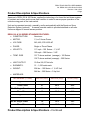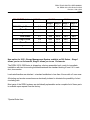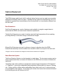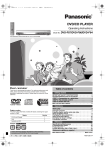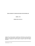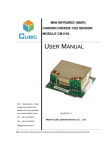
1
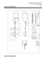
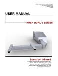
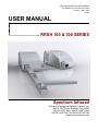
RRSH TRACK SWITCH USER MANUAL No: RRSH 100 & 300 Series 5122010 Revision: 009 1/2012 0 Page USER MANUAL RRSH 100 & 300 SERIES Spectrum Infrared A division of Advanced Detection Systems, Inc. 1440 E. 357th Street, Eastlake, Ohio 44095 440-951-6061 Main / 440-951-6687 Sales 440-951-6641 Fax / 800-605-9818 Toll Free www.spectruminfrared.com RRSH TRACK SWITCH USER MANUAL No: RRSH 100 & 300 Series 5122010 Revision: 009 1/2012 1 Page INDEX Page No. 1 Product Description & Specifications 2-3 Optional Equipment 4 General Installation Instructions 5 Layout Configurations 6-7 Warranty 8 Important Notice 9 RRSH TRACK SWITCH USER MANUAL No: RRSH 100 & 300 Series 5122010 Revision: 009 1/2012 2 Page Product Description & Specifications Spectrum’s RRSH 100 & 300 Series, applies the technology of a forced hot air blower system to maintain an ice-free and/or snow-free condition in order to assure proper operation of the critical moving parts of the track switch. Unit can be operated remotely, manually, and/or automatically with the Spectrum Snow Detection System (optional). A manual override switch is provided standard on all units. Units are shipped in remote access position. RRSH 100 & 300 SERIES STANDARD FEATURES: CONSTRUCTION: Aluminum MOTOR: 1½ or 3 Horse Power VOLTAGE: 240, 480, 575 & 600 AC PHASE: Single or Three Phase VELOCITY: 117 mph – 100 Series – 1 ½ HP 189 mph – 300 Series – 3 HP TEMP. RISE 151°F above ambient (average) – 100 Series 102°F above ambient (average) – 300 Series HEAT OUTPUT: 19.5kw / 66,537 btu’s/hr ELEMENTS: 12 - 1,625 watts each WEIGHT: 224 lbs – 100 Series – 1 ½ HP Unit 244 lbs – 300 Series – 3 Hp Unit AMPERAGE: MOTOR (amps) HEATER (amps) TOTAL (amps) 240 AC Single Phase 4.6 81.2 85.8 Three Phase 2.7 46.9 49.6 2.3 40.6 42.9 Three Phase 1.3 23.5 24.8 575 AC Single Phase 1.9 33.9 35.8 Three Phase 1.1 19.6 20.7 600 AC Single Phase 1.8 32.5 34.3 Three Phase 1.08 18.8 19.9 100 SERIES (1.12kw) 480 AC Single Phase* Product Description & Specifications - Continued RRSH TRACK SWITCH USER MANUAL No: RRSH 100 & 300 Series 5122010 Revision: 009 1/2012 3 Page 300 SERIES (2.24kw) MOTOR (amps) HEATER (amps) TOTAL (amps) Stage 1 Stage 2 Stage 1 Stage 2 240 AC Single Phase 9.3 54.2 81.2 63.5 90.5 Three Phase 5.4 31.3 46.9 36.7 52.3 4.7 27.1 40.6 31.8 45.3 Three Phase 2.7 15.6 23.5 18.3 26.2 575 AC Single Phase 3.9 22.6 33.9 26.5 37.8 Three Phase 2.3 13.0 19.6 15.3 21.9 600 AC Single Phase 3.7 21.7 32.5 25.4 36.2 Three Phase 2.15 12.5 18.8 14.6 21 480 AC Single Phase* New option for 2012 - Energy Management System available on 300 Series – Stage 1 allows you to run 8 elements, Stage 2 allows you to run 12 elements. The RRSH 100 & 300 Series is shipped as a factory-assembled unit, ready for immediate installation with two tie mounting brackets/hardware the standard ducting of one 6.4 ft. main duct, two nozzles. Load-rated handles are attached – standard installation is less than 4 hours with a 2 man crew. All ducting and nozzle connections are electrically isolated to eliminate the possibility of short circulating rails. Most parts of the RRSH systems are individually replaceable and a complete list of these parts is available upon request from the factory. *Special Order Item. RRSH TRACK SWITCH USER MANUAL No: RRSH 100 & 300 Series 5122010 Revision: 009 1/2012 4 Page Optional Equipment The RRSH design readily lends itself to optional design features and can easily accommodate additional functionality based on needs. Installations may require the heater/blower unit to be installed at a greater than normal distance from the track rails, or at an elevation different from the track rails. Duct Extensions: Solid Duct Extensions are made of aluminum and available in straight or angled ducts to assure that the RRSH unit meets track clearance requirements. Flexible Duct Extensions are made of stainless steel with high temperature silicone packing providing flexibility for elevation change or directional changes. Mitered Duct Extensions are used to achieve a change in elevation when the RRSH heater/blower assembly must be installed at an elevation which is not equal to the track rails. *Flanges on the duct extensions are designed to allow all duct extensions to fit together. Snow Detection System: The Snow Detection System can be integrated or stand-alone. The two sensor system can be easily implemented where one sensor is attached to the RRSH and one sensor is attached at track level. Operating mode- when ambient air temperature reaches trigger temperature of 38 degrees F +/- 2 degrees F. (pre-set/non-adjustable) and precipitation is presumed to be snow or freezing rain. Drying cycle/turn-off(pre-set/non-adjustable) timer allows unit to run 5 continuous hours once precipitation has stopped. This drying cycle reduces the chance that moisture left behind by the melting process will refreeze into ice. RRSH TRACK SWITCH USER MANUAL No: RRSH 100 & 300 Series 5122010 Revision: 009 1/2012 5 Page General Installation Instructions When the power supply and control circuits are available at the switch site, the typical installation takes only three to four hours. Installation consist of inserting the main duct in the crib area one or two tie spaces in front of the switch point, setting the blower housing on a level surface and connecting the nozzles. It is most important that your power supply deliver the specified voltage and load carrying capacity. Make sure power supply cable is the right size and that your electrical service is sufficient to operate the unit properly. Low voltage will result in reduced heater effectiveness. The two nozzles, which are located between the rails, are positioned to direct forced air at the switch points. The body of the heat is attached to the main duct, and brought to a level position at the side of the track. This area should be approximately 6 feet long by 6 feet wide, and should be 9 inches lower than the top surface of the rail ties, if flex duct is not used. Connection of the electrical power source and control circuit completes the installation and the unit is ready to operate. Track Installation: The unit should be positioned so that the ends of the nozzles are five to ten inches from the tip of the switch point. Once the proper crib area has been determined, it should be cleared of adequate ballast material to allow the duct unit to slide under the rail and be positioned. The main heater duct with two nozzles is now placed in the crib so that the open end of the duct passes under the stock rail. The closed end of the duct is to be positioned so that it is approximately 6 inches from the rail. The main heater duct in now fastened to the adjacent ties with aluminum tie-down angles. The tie-down angles are to be lag-screwed into the ties. The main body of the unit is now bolted to the main heater duct at the matching flanged end. Loosen the nozzle hold-down clamps and direct the nozzle at the open point. The objective here is to point the nozzle so that the greatest volume of air possible will flow between the point and stock rail. Lock each nozzle in place making sure each of the hold-down clamps is securely tightened. ~HIGH VOLTAGE~ Control circuits operate at 110 volts RRSH TRACK SWITCH USER MANUAL No: RRSH 100 & 300 Series 5122010 Revision: 009 1/2012 6 Page Layout Configuration Layout Configuration RRSH TRACK SWITCH USER MANUAL No: RRSH 100 & 300 Series 5122010 Revision: 009 1/2012 7 Page RRSH TRACK SWITCH USER MANUAL No: RRSH 100 & 300 Series 5122010 Revision: 009 1/2012 8 Page Warranty RRSH LIMITED WARRANTY Spectrum Infrared, A division of Advanced Detection Systems, Inc.,(“Spectrum”) offers a limited warranty of merchantability for its products. Spectrum’s limited warranty of merchantability is under the following conditions: 1. Spectrum warrants against defects in workmanship and materials for five (5) years from the date of purchase. 2. Customer must provide Spectrum written proof of the date of the product’s purchase. 3. Customer shall be responsible for all costs incurred in the removal and shipment of the product under warranty back to Spectrum. Spectrum will repair or replace, at its option, the product and ship the product back to customer. Customer is responsible for all costs associated with re-installation of the product. 4. Warranty does not apply to damage from accident, misuse, or alteration; nor where the connected voltage is more than 5% above or below the nameplate voltage; nor to equipment improperly installed or wired or maintained in violation of the product’s installation instructions. SPECTRUM SHALL NOT BE LIABLE FOR CONSEQUENTIAL DAMAGES ARISING WITH RESPECT TO THE PRODUCT, WHETHER BASED UPON NEGLIGENCE, TORT, STRICT LIABILITY, OR CONTRACT. Some states do not allow the exclusion or limitation of incidental or consequential damages, so the above exclusion or limitation may not apply to you. This warranty gives you specific legal rights, and you may also have other rights which vary from state to state. The above limited warranty of merchantability is the exclusive remedy available by customer from Spectrum. There are no warranties which extend beyond the face hereof including, but not limited, warranty for a particular purpose. This limited warranty of merchantability is meant to comply with exclusions and modifications of warranties under the Uniform Commercial Code section 2-316. RETURN ADDRESS: SPECTRUM INFRARED th 1440 E. 357 STREET EASTLAKE, OHIO 44095 Merchandise returned to the factory must be accompanied by a return authorization number available from Spectrum Infrared. When requesting return authorization, include all catalog numbers shown on the products Revised 3-2011. RRSH TRACK SWITCH USER MANUAL No: RRSH 100 & 300 Series 5122010 Revision: 009 1/2012 9 Page IMPORTANT NOTICE: BLOWER FAN ROTATION MUST BE VERIFIED FOR CORRECT DIRECTION AFTER ATTACHING 3 PHASE POWER TO POWER BLOCK. BLOWER FAN MUST ROTATE COUNTER-CLOCKWISE WHEN VIEWED FACING THE GRILL SIDE OF THE SWITCH HEATER. IF ROTATION IS INCORRECT CHANGE ORIENTATION OF INPUT WIRES (L1, L2, L3) TO POWER BLOCK UNTIL CORRECT ROTATION IS OBTAINED. FAILURE TO VERIFY FAN ROTATION WILL CAUSE DAMAGE TO HEATER SECTION AND WILL VOID WARRANTY. SUGGESTED PROCEEDURE: 1. TURN BLOWER CONTROL SWITCH TO OFF POSITION. TURN HEATER SELECTOR SWITCH TO OFF (MIDDLE POSTION). 2. CONNECT POWER TO POWER BLOCK LOCATED INSIDE CONTROL BOX 3. BRIEFLY TURN BLOWER CONTROL SWITCH TO ON POSITION TO START MOTOR BLOWER. VERIFY THAT FAN WHEEL IS ROTATING COUNTER-CLOCKWISE WHEN VIEWED THROUGH THE GRILL. TURN SWITCH TO OFF POSITION TO TURN OFF BLOWER. 4. IF ROTATION IS INCORRECT DISCONNECT POWER AND INTERCHANGE POSTION OF L1 L2 OR L3 LEAD AS REQUIRED TO GET CORRECT PHASING. 5. RE-CHECK FAN ROTATION PER STEP 3RETURN BLOWER CONTROL SWITCH AND HEATER CONTROL SWITCH TO DESIRED OPERATING POSITION.