1
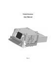
HW200
Universal USB Interface
For Coin And Bill Validators
User Manual
Version 1.6
The HW200, ‘Universal’ USB Interface Was Awarded “Best of ShowHardware” at Kioskcom 2001 in Orlando.
Hemisphere West
1.0
Introduction
The HW200 is a product built to interface to a USB Hub or to the Root Hub on the PC. It converts the
industrial standard interface of a banknote or coin acceptor to an easy to use USB protocol for PC user to
program with.
Note: HW200 converts data from the acceptor into the USB language only if the acceptor gives
out the information. For instance, if the acceptor does not have the capability to give a
CASHBOX FULL message upon a cashbox full condition, HW200 will NOT have this
message to report.
2.0
Communications
HW200 conforms to USB 1.1 specification issued by the USB Implementers Forum. It is a low speed
device (1.5Mbit/sec) supporting EndPoint 0 (Interrupt IN/OUT and Setup) and EndPoint 1 (Interrupt IN
only) reports. When HW200 is attached to the USB bus, an enumeration process takes place automatically
by the Host Operation System. Upon successful enumeration, HW200 is registered as a HID-class device
under the Human Interface Device category specified by the USB specification.
The Host sends poll to request information from the HW200 at a periodic rate. HW200 answers to the poll
and reports all the happening events. This poll rate should be set at a moderate rate fast enough to keep up
with the performance (accepting speed) of a bill/coin acceptor and not to exceed the legacy of the Host
system.
There are two communication sides on the HW200. The UPSTREAM side refers to the communication
between the Host system and the HW200 (USB side). The DOWNSTREAM side refers to the
communication between the HW200 and the acceptor side (acceptor side).
2.1
GENERAL DATA
Host -
Refers to the application program or the computer system that handles the USB
communication and interpretation of all the messages.
Token -
A collective term to refer to a banknote and a coin.
Hub -
Refers to an external hub for USB connections or the Root Hub built on the PC
motherboard. In this document it refers to the port that the HW200 connects to.
Credit stack -
HW200 has a 4 level of credit stack in Parallel Mode. This stack is a FIFO type and
holds up to 4 distinct credits from an acceptor. Credits issued by the acceptor are
Page 2 of 14
HW200 Manual, REV1.6 12/02
Hemisphere West
temporary stored in the HW200 and wait to be reported to the Host in the future polls. In
a slow polling system, if the credits enter to the 2nd level of stack, HW200 will disable
the acceptor so that no more acceptance of the acceptor will be allowed. But the
transactions already taken place will also be scored to the 3rd and 4th level of stack.
In Pulse Mode, HW200 can hold up to 260 distinct pulses from an acceptor. If the Host
does not poll for the credited value before the pulses accumulate over 260 counts, the
credit stack will overflow and credits will be lost. This is not likely to happen as in
normal situation, a 20-pulse pulse chain represents a $20 bill accepted.
In Serial Mode, HW200 acts as a passive translator between the USB side and the
acceptor side. Any credit received from the acceptor is reported directly to the Host on
the next poll. No credit storage is used in this mode.
Suspend mode - According to the USB 1.1 specification, all devices should enter a suspend (power
saving) mode upon 3msec of inactivity of the USB bus. This includes the loss in
communication with the Host or the Host Operation System disable the device etc.
HW200 will enter this suspend mode after doing the followings:
1. Disable the acceptor.
2. Continue with the current credit detection if there is any.
3. Wait for 100msec for any incoming transactions that has already taken place.
On exiting the Suspend Mode, HW200 will be reset by the inherent USB Bus reset. Any
prior status / setup will be cleared and back to their default stage.
Enumeration -
When an USB device is attached to the Hub, the Host Operation System will start an
enumeration process. During this process, information and capability of the device is
sent to the PC. The Host Operation System will determine whether or not to configure
the device and register as an active device depending on the existing resources available
in the system. The factors that may inhibit a device from being configured include the
data bandwidth requested by the device, the CPU usage of the system and the traffic
already in the USB bus etc. Only upon successful enumeration, the device is given a
resource handle for application program to access. In MS Windows 9X/2K/Me, a
registered USB device is shown under the System Properties/Device Manager.
Bus Address -
According to the USB spec., up to 127 devices can be connected to the same USB bus on
a single computer system. The attachment of the device should be done without user
settings and be configured automatically by the Host Operation System. But in some
situation, it is impractical or illogical to connect the same device more than one onto a
single system. The limitation is due to the “fighting” for the same resources and
interruption between the same kind of devices (For example: keyboard, mouse…).
For HW200, it has the capability to identify itself among a multi-HW200 system. The
HW200 utilities a unique Bus Address Setting to give itself a unique Bus Address for
identification and for resources allocation. This Bus Address is a proprietary value in the
product and will not interfere the normal USB operation. By using different Bus Address
Settings, up to 4 HW200 can be attached on a single system simultaneously. Upon
successful enumerations, each HW200 is assigned with different resource handle. The
application program should be able to retrieve the different handles from the Operating
Page 3 of 14
HW200 Manual, REV1.6 12/02
Hemisphere West
System and communicate with the HW200s independently. End user can easily identify
each HW200 just by observing to the jumper settings.
Sequence No. -
2.2
In USB development, it is a common issue that the application program cannot see a real
time upstream message sent from the device. That is to say, all the upstream messages
sent from the device are stored to the bottom of the Host computer buffer. Only by
continual “popping” of the buffer will the latest message be able to seen by the program.
This leads to an unsynchronised situation in the HW200 communication. When the Host
polls the HW200 for the most current status, the Host will always see the precedent
message stored in the computer buffer. The Host has to keep on retrieving the buffer
messages until the last message pops up to the top of the buffer.
In MS Windows 98 this buffer has a fixed storage of 2 messages. In MS Windows
98SE/2K/Me, the default number is 8. User can change this number with
SetNumInputBuffers register. To cope with this variance of Operating Systems, HW200
incorporates with a message Sequence No. to keep track of the messages. This number is
added to both the upstream and downstream messages for the detection of the correct
sequence of the receiving message. The Host will keep polling for the same command
until the Sequence No. received from HW200 is the same as the one sent out. On the
other hand, HW200 will keep resending the same message until the Host changes the
same Sequence No.
INTERFACE MODE
The HW200 has the capability to communicate in 3 different protocols on its downstream communication.
These protocols are the most common type of communication methods found in modern electronic
coin/bill acceptors. With a choice of specific harnesses, the usability of the HW200 can be expanded
beyond the listed versatilities.
Parallel Mode - This interface utilities different Vend Lines to represent different values of token. Upon
receiving a token, the acceptor will give a pulse on the respective Vend Line and HW200
will score the value of credit based on the Vend Line #. Disable/Enable of the acceptor is
done via the Master Enable Bit in the upstream protocol. Individual Channel Enabling is
not support in this mode.
Pulse Mode -
This interface utilities a single output line to “pulse” out the credits. Upon receiving a
token, the acceptor will toggle (OFF-ON-OFF) the output credit line a number of times
same as the value of the accepted token. The normal toggling speed varies from 50ms to
300ms. HW200 will report the occurrence of each toggle as an individual event to the
Host. Disable/Enable of the acceptor is done via the Master Enable Bit in the upstream
protocol. Individual Channel Enabling is not support in this mode.
Serial Mode -
There are different types of serial interface appear in the industry. HW200 adopted the
most common type of serial interface, the Bidirectional Serial Protocol used by the Mars
Electronic International. With this high level communication protocol, additional
features like: Individual Channel Enabling, detail report of acceptor Events/Failure can
Page 4 of 14
HW200 Manual, REV1.6 12/02
Hemisphere West
be taken place. This interface utilities 3 wires, TXD/RXD/GND as the communication
media.
2.3
UPSTREAM MESSAGE FORMAT
Host-to-HW200
Format: >> Cmd Byte, Bill Field Data 1, Bill Field Data 0, Mode Bits, Sequence No.
Cmd Byte
- Control commands send to MF200.
Bill Field Data 1 - Upper (16th – 9th ) enabled denomination channels.
Bill Field Data 0 - Lower (8th – 0th ) enabled denomination channels.
Mode Bits
- Compatibility settings and other control commands.
Sequence No.
- Host sequence number.
Example:
01 00 00 10 02
(Master Enabled; Parallel Mode; Enable Polarity: Active LO; Failure Polarity: Active HI)
Cmd Byte
Bit 0Master Enable Bit. This bit controls the Enable Pin on the I/O Device port to enable/disable an acceptor. The
polarity of operation is defined in Mode Bit. Not applicable in Serial Mode.
1 = Master Enabled / 0 = Master Disabled
Bit 1Escrow Control Bit. This bit controls the Escrow function of an acceptor. This function is only applicable to those
acceptors with an Escrow capability.
Set to 0. Reserved for future use.
Bit 2Stack Control Bit. To notify an acceptor to accept the token that is held in escrow position. For Serial Mode only.
1 = Stack / 0 = Keep in escrow
Bit 3Return Control Bit. To notify an acceptor to return a token that is held in escrow position. For Serial Mode only.
1 = Return / 0 = Keep in escrow
Bit 4 – 7
Set to 0. Reserved for future use.
Bill Field Data 1
Upper Individual Channel Enabling Bits. To turn on / off an individual channel of an acceptor.
Set to 00h for those acceptors that do not support this feature. For Serial Mode only.
Bit 0Bit 1Bit 2Bit 3Bit 4Bit 5Bit 6Bit 7-
9th Channel (1=Enabled / 0=Disabled)
10th Channel (1=Enabled / 0=Disabled)
11th Channel (1=Enabled / 0=Disabled)
12th Channel (1=Enabled / 0=Disabled)
13th Channel (1=Enabled / 0=Disabled)
14th Channel (1=Enabled / 0=Disabled)
15th Channel (1=Enabled / 0=Disabled)
16th Channel (1=Enabled / 0=Disabled)
Page 5 of 14
HW200 Manual, REV1.6 12/02
Hemisphere West
Bill Field Data 0
Lower Individual Channel Enabling Bits. To turn on / off an individual channel of an acceptor.
Set to 00h for those acceptors that do not support this feature. For Serial Mode only.
Bit 0Bit 1Bit 2Bit 3Bit 4Bit 5Bit 6Bit 7-
1st Channel (1=Enabled / 0=Disabled)
2nd Channel (1=Enabled / 0=Disabled)
3rd Channel (1=Enabled / 0=Disabled)
4th Channel (1=Enabled / 0=Disabled)
5th Channel (1=Enabled / 0=Disabled)
6th Channel (1=Enabled / 0=Disabled)
7th Channel (1=Enabled / 0=Disabled)
8th Channel (1=Enabled / 0=Disabled)
Mode Bits
Bit 0-1
Interface Mode Selection Bits.
00 = Parallel Mode.
01 = Pulse Mode.
10 = Serial Mode.
11 = Reserved.
Bit 2Set to 0. Reserved for future use.
Bit 3Master Enable Polarity Bit. Select this pin according to input logic level of the Enable control line of the acceptor.
Not applicable to Serial Mode, set to 0.
1 = Active HI / 0 = Active LO
Bit 4Failure Polarity Bit. Select this pin according to the output logic level of the Failure signal of the acceptor.
Not applicable to Serial Mode, set to 0.
1 = Active HI / 0 = Active LO
Bit 5-7
Set to 0. Reserved for future use.
Sequence No.
Initiated by the Host. It starts from 00h and increments on successive messages. It rollovers at FFh and starts at 00h again. The
Host should send the same message continuously until HW200 responses with the same Sequence No.
Caution:
On Power Up / USB Bus reset, MF200 will clear all user settings. Stored credits
will be lost also. Control command & Mode Bits must be sent in order to initialise
HW200 to the proper stage.
Caution:
On changing the Interface Mode bit, HW200 will discard all its current status,
including stored credits amd switch to a new interface mode instantaneously.
Page 6 of 14
HW200 Manual, REV1.6 12/02
Hemisphere West
HW200-to-Host
Format: >> Status, Events, Expansion, Bill Field Data, Sequence No.
Status -
Current status of HW200.
Events -
Events experienced by HW200.
Expansion -
Reserved for future use. Always returns 00h
Bill Field Data -
Denomination channel. Binary Format.
Sequence No. -
Sequence No. as sent by the Host.
Example:
08 00 00 02 02
Stacked. Channel 2 in concern.
Status
Bit 0Bit 1Bit 2Bit 3Bit 4Bit 5Bit 6Bit 7-
Accepting
Escrowed
Stacking
Stacked
Returning
Returned
Rejecting
Rejected
Events
Bit 0Bit 1Bit 2Bit 3Bit 4Bit 5Bit 6Bit 7-
Failure
( =1 on any kind of failure).
Power Up
( = 1 on power up).
Cashbox Full ( =1 if the cashbox of the acceptor is full).
Cheated
( =1 if a cheat / stringing / Yo -Yo is detected).
Bill/Coin Jammed
( =1 if the acceptor is jammed).
Cashbox Present
( =1 if the cashbox of the acceptor is attached).
Invalid Command
( =1 if an invalid command is received).
Set to 0. Reserved for future use.
( =1 if a token is taking in and before Escrow position).
( =1 if a token is in Escrow position).
( =1 if a token is accepting and being stacked).
( =1 if a token is successfully stacked and credit received from acceptor).
( =1 if a token is being returned by the Host).
( =1 if a token has been returned by the Host).
( =1 if a token is being rejected by the acceptor).
( =1 if a token has been rejected by the acceptor).
Expansion
Reserved for future use. Always returns 00h.
Bill Field Data
Report of denomination channel that is under concerned. Binary format.
Sequence No.
HW200 will give the same Sequence No. received from the Host for synchronization purpose.
Page 7 of 14
HW200 Manual, REV1.6 12/02
Hemisphere West
3.0
ELECTRICAL HOOKUP
POWER
PLUG
HW200, USB I/F
POWER
USB TYPE ‘B’
RECEPTACLE
UPSTREAM COMM.
RELAY CONTACT
(AC110V model only)
DEVICE
I/O PORT
CREDIT / DOWNSTREAM
(Figure 1)
DC12V model
POWER PLUG
- A power supply input: Center Conductor +12VDC, Outer: Ground/Earth
Power requirement for typical coin acceptor : 12 VDC 500mA.
Power requirement for typical banknote acceptor : 12VDC 1.5A.
USB TYPE ‘B’
RECEPTACLE
- For connection to computer USB port or USB Hub Uplink port.
DEVICE I/O PORT
- A 16-pin IDC socket for connection with bill/coin acceptor.
RELAY CONTACT
(AC110V model only)
- Refers to Section 3.2
POWER LIGHT
- Green LED lights up on power up.
UPSTREAM SIGNAL - Yellow LED lights up after enumeration and blinks on every upstream
LIGHT
communication.
CREDIT LIGHT
(for Parallel / Pulse Mode)
- Red LED blinks on every received credit. It will stay on until all the credits
has been reported to the Host.
DOWNSTREAM
SIGNAL LIGHT
(for RS232 Mode)
- Red LED blinks on every downstream communication with the acceptor.
Page 8 of 14
HW200 Manual, REV1.6 12/02
Hemisphere West
3.1
DEVICE I/O PORT configuration
15
16
1
2
(Figure 2. Facing towards I/O connector)
Pin 1
Pin 2
Pin 3
Pin 4
Pin 5
Pin 6
Pin 7
Pin 8
Pin 9
Pin 10
Pin 11
Pin 12
Pin 13
Pin 14
Pin 15
Pin 16
Power GND
Power +12V
~Credit Channel 5 (Input: Active LOW)
~Credit Channel 6 (Input: Selectable Active HIGH / LOW)
FAILURE (Input: Selectable Active HIGH / LOW)
DISABLE / ENABLE (Output: Selectable Active HIGH / LOW)
~Credit Channel 1 (Input: Active LOW)
~Credit Channel 2 (Input: Active LOW)
~Credit Channel 3 (Input: Active LOW)
~Credit Channel 4 (Input: Active LOW)
SERIAL TXD / ~ESCROW
SERIAL RXD
Not used
Limited Power Source. +5V with a 100ohm resistor in series.
Not used
Signal GND
WARNING: Do not apply voltage higher than +5V or lower than 0V to any signal pins.
Otherwise severe damage may occurs to MF200 and computer system.
POWER (Input: Power). See Figure 3.
HW200 is built with Port Power Mode selected by default. User can specify their choice when ordering.
External Power Mode. Jumper S5 position: 2-3
Under this mode, HW200 gets its power together with the attached acceptor from the ‘POWER PLUG’
input. This mode is used only when the USB host is having a tight power budget.
Port Power Mode. Jumper S5 position: 1-2
Under this mode, HW200 gets its power from the USB port. Once the USB cable is connected, HW200 is
operating. The attached acceptor gets its power from the ‘POWER PLUG’. For AC110V model, Port
Power mode must be selected as the acceptor is getting power from 110VAC power line.
LIMITED POWER SOURCE (Output: Power) . See Figure 3.
This power source is for logic device and LED usage only.
WARNING: Do not connect any device that draws more than 20mA to PIN 14. Otherwise damage
may occurs to HW200 and computer system.
Page 9 of 14
HW200 Manual, REV1.6 12/02
Hemisphere West
(Figure 3)
DISABLE / ENABLE (Output, open collector sinks for 50mA with optional pull-up resistor). See
Figure 4.
This pin will be set HIGH or LOW according to the Master Enable Bit and the Master Enable Polarity Bit
in the upstream protocol to enable or disable the acceptor. In Parallel / Pulse Mode, upon enabled, the
acceptor should enter its normal operation state and be ready to accept tokens. HW200 will disable the
acceptor on certain circumstances including:
1. Entering suspend mode.
2. Master Disabled.
3. 2nd level of stack credit entered.
Not applicable to Serial Mode, leave this pin unconnected.
(Figure 4)
Page 10 of 14
HW200 Manual, REV1.6 12/02
Hemisphere West
FAILURE (Input). See Figure 5.
The active state of this pin depends on the Failure Polarity Bit set in the upstream protocol and the jumper
S10/S11/S12 settings. HW200 will report a failure message to the Host upon receiving a trigger on this
pin. Not applicable to Serial Mode, leave this pin unconnected.
Active Low setting: Jumper S10: Close S11: Open S12: Open
Active High setting: Jumper S10: Open S11: Close S12: Close
WARNING: Do not apply jumpers other than the above two settings. Otherwise MF200 internal
circuit gets damage.
(Figure 5)
~CREDIT CHANNEL # 1 to #6 (Input: Active Low). See Figure 6.
Parallel Mode
6 Credit Vend lines representing 6 different kinds of token accepted by the acceptor. The acceptor should
generate a Logic Low pulse on the Credit Line corresponds to that accepted token. The duration of the
pulse should be within a time frame of 30msec to 200msec. A 10msec debounce period is added to the
trailing edge (rising) of the pulse to avoid false trigger due to slow skew rate of the output driver of the
acceptor. Any noise/signal received during the debounce period is ignored.
NOTE:
For proper crediting on Channel #6, set Jumper S7: Close
Page 11 of 14
S8: Open
S9: Open.
HW200 Manual, REV1.6 12/02
Hemisphere West
Pulse Mode
Any of the 6 credit lines can be used as the Credit Input. By convention, Channel #6 is used. The acceptor
should generate a chain of pulses equivalent to the value of the accepted token. The duration of each pulse
should be within 30msec to 200msec. A 10msec debounce period is added to the trailing edge of each
pulse to avoid false trigger due to slow skew rate of the output driver of the acceptor.
When using Channel #6 is used, an extra option is given. You can choose the trigger of credit to be Active
Low or Active High by set Jumpers to the following combinations.
Active Low setting: Jumper S7: Close S8: Open S9: Open
Active High setting: Jumper S7: Open S8: Close S9: Close
WARNING: Do not apply jumpers other than the above two settings. Otherwise MF200 internal
circuit may gets damage.
Serial Mode
Not applicable. Leave these pins unconnected.
(Figure 6)
Page 12 of 14
HW200 Manual, REV1.6 12/02
Hemisphere West
TXD / RXD (Serial Mode only). See Figure 7.
A serial transmission / reception port to acceptor.
Not applicable to Parallel / Pulse Mode, leave these pins unconnected.
(Figure 7)
3.2
POWER RELAY CONTACT PORT configuration (OPTIONAL)
6
1
(Figure 8. Facing towards I/O connector)
Pin 1
Pin 2
Pin 3
Pin 4
Pin 5
Pin 6
AC 110V Neutral
AC 110V Hot
AC Hot Enable
Not Used
Relay contact +
Relay contact - / also serves as Signal GND
The HW200 has an optional to interface with acceptors that takes AC 110V input power and has a relay
contact for giving out credits. MAG50™ is a typical example. User can specify this option when ordering.
MAG50™ is a registered product of Coin Acceptors, Inc. (Coinco).
WARNING: Always disconnects from Mains AC 110V power before manipulate on connectors.
Otherwise electrical shock hazard may occur.
Page 13 of 14
HW200 Manual, REV1.6 12/02
Hemisphere West
3.3
BUS ADDRESS configuration
The Bus Address Setting jumpers locate inside the cabin. There are 4 different settings for the 4 distinctive
address IDs. Choose the address that is unique in the system and place the jumper in the corresponding
position. See figure 8.
S1
S2
S3
S4
S1 = Address 01
S2 = Address 02
S3 = Address 03
S4 = Address 04
(Figure 9)
Observe the following procedure when doing the change.
1.
2.
3.
4.
5.
6.
7.
8.
Stop all USB communication on the Host.
Unplug the power cable to HW200.
Disconnect HW200 from the Hub.
Open the back cover and locate the Address jumpers inside the cabin.
Change the jumper setting according to your needs. The default one is at Address 01. Do not set
more than one device with the same address on a single system.
Replace the back cover.
Reattach the power cable and USB cable.
Start the USB communication on the Host. The HW200 should show a new Address ID.
Page 14 of 14
HW200 Manual, REV1.6 12/02