1
User’s Manual
CubeSuite Ver.1.40
Integrated Development Environment
User’s Manual: 78K0 Design
Target Device
78K0 Microcontroller
All information contained in these materials, including products and product specifications,
represents information on the product at the time of publication and is subject to change by
Renesas Electronics Corp. without notice. Please review the latest information published by
Renesas Electronics Corp. through various means, including the Renesas Electronics Corp.
website (http://www.renesas.com).
www.renesas.com
Rev.1.00
Sep 2010
Notice
1.
2.
3.
4.
5.
6.
7.
All information included in this document is current as of the date this document is issued. Such information, however, is
subject to change without any prior notice. Before purchasing or using any Renesas Electronics products listed herein, please
confirm the latest product information with a Renesas Electronics sales office. Also, please pay regular and careful attention to
additional and different information to be disclosed by Renesas Electronics such as that disclosed through our website.
Renesas Electronics does not assume any liability for infringement of patents, copyrights, or other intellectual property rights
of third parties by or arising from the use of Renesas Electronics products or technical information described in this document.
No license, express, implied or otherwise, is granted hereby under any patents, copyrights or other intellectual property rights
of Renesas Electronics or others.
You should not alter, modify, copy, or otherwise misappropriate any Renesas Electronics product, whether in whole or in part.
Descriptions of circuits, software and other related information in this document are provided only to illustrate the operation of
semiconductor products and application examples. You are fully responsible for the incorporation of these circuits, software,
and information in the design of your equipment. Renesas Electronics assumes no responsibility for any losses incurred by
you or third parties arising from the use of these circuits, software, or information.
When exporting the products or technology described in this document, you should comply with the applicable export control
laws and regulations and follow the procedures required by such laws and regulations. You should not use Renesas
Electronics products or the technology described in this document for any purpose relating to military applications or use by
the military, including but not limited to the development of weapons of mass destruction. Renesas Electronics products and
technology may not be used for or incorporated into any products or systems whose manufacture, use, or sale is prohibited
under any applicable domestic or foreign laws or regulations.
Renesas Electronics has used reasonable care in preparing the information included in this document, but Renesas Electronics
does not warrant that such information is error free. Renesas Electronics assumes no liability whatsoever for any damages
incurred by you resulting from errors in or omissions from the information included herein.
Renesas Electronics products are classified according to the following three quality grades: “Standard”, “High Quality”, and
“Specific”. The recommended applications for each Renesas Electronics product depends on the product’s quality grade, as
indicated below. You must check the quality grade of each Renesas Electronics product before using it in a particular
application. You may not use any Renesas Electronics product for any application categorized as “Specific” without the prior
written consent of Renesas Electronics. Further, you may not use any Renesas Electronics product for any application for
which it is not intended without the prior written consent of Renesas Electronics. Renesas Electronics shall not be in any way
liable for any damages or losses incurred by you or third parties arising from the use of any Renesas Electronics product for an
application categorized as “Specific” or for which the product is not intended where you have failed to obtain the prior written
consent of Renesas Electronics. The quality grade of each Renesas Electronics product is “Standard” unless otherwise
expressly specified in a Renesas Electronics data sheets or data books, etc.
“Standard”:
8.
9.
10.
11.
12.
Computers; office equipment; communications equipment; test and measurement equipment; audio and visual
equipment; home electronic appliances; machine tools; personal electronic equipment; and industrial robots.
“High Quality”: Transportation equipment (automobiles, trains, ships, etc.); traffic control systems; anti-disaster systems; anticrime systems; safety equipment; and medical equipment not specifically designed for life support.
“Specific”:
Aircraft; aerospace equipment; submersible repeaters; nuclear reactor control systems; medical equipment or
systems for life support (e.g. artificial life support devices or systems), surgical implantations, or healthcare
intervention (e.g. excision, etc.), and any other applications or purposes that pose a direct threat to human life.
You should use the Renesas Electronics products described in this document within the range specified by Renesas Electronics,
especially with respect to the maximum rating, operating supply voltage range, movement power voltage range, heat radiation
characteristics, installation and other product characteristics. Renesas Electronics shall have no liability for malfunctions or
damages arising out of the use of Renesas Electronics products beyond such specified ranges.
Although Renesas Electronics endeavors to improve the quality and reliability of its products, semiconductor products have
specific characteristics such as the occurrence of failure at a certain rate and malfunctions under certain use conditions. Further,
Renesas Electronics products are not subject to radiation resistance design. Please be sure to implement safety measures to
guard them against the possibility of physical injury, and injury or damage caused by fire in the event of the failure of a
Renesas Electronics product, such as safety design for hardware and software including but not limited to redundancy, fire
control and malfunction prevention, appropriate treatment for aging degradation or any other appropriate measures. Because
the evaluation of microcomputer software alone is very difficult, please evaluate the safety of the final products or system
manufactured by you.
Please contact a Renesas Electronics sales office for details as to environmental matters such as the environmental
compatibility of each Renesas Electronics product. Please use Renesas Electronics products in compliance with all applicable
laws and regulations that regulate the inclusion or use of controlled substances, including without limitation, the EU RoHS
Directive. Renesas Electronics assumes no liability for damages or losses occurring as a result of your noncompliance with
applicable laws and regulations.
This document may not be reproduced or duplicated, in any form, in whole or in part, without prior written consent of Renesas
Electronics.
Please contact a Renesas Electronics sales office if you have any questions regarding the information contained in this
document or Renesas Electronics products, or if you have any other inquiries.
(Note 1) “Renesas Electronics” as used in this document means Renesas Electronics Corporation and also includes its majorityowned subsidiaries.
(Note 2) “Renesas Electronics product(s)” means any product developed or manufactured by or for Renesas Electronics.
How to Use This Manual
This manual describes the role of the CubeSuite integrated development environment for developing applications
and systems for 78K0 microcontrollers, and provides an outline of its features.
CubeSuite is an integrated development environment (IDE) for 78K0 microcontrollers, integrating the necessary
tools for the development phase of software (e.g. design, implementation, and debugging) into a single platform.
By providing an integrated environment, it is possible to perform all development using just this product, without
the need to use many different tools separately.
Readers
This manual is intended for users who wish to understand the functions of the
CubeSuite and design software and hardware application systems.
Purpose
This manual is intended to give users an understanding of the functions of the
Cubesuite to use for reference in developing the hardware or software of systems using
these devices.
Organization
This manual can be broadly divided into the following units.
CHAPTER 1 GENERAL
CHAPTER 2 FUNCTIONS (Pin Configurator)
CHAPTER 3 FUNCTIONS (Code Generator)
APPENDIX A WINDOW REFERENCE
APPENDIX B OUTPUT FILES
APPENDIX C API FUNCTIONS
APPENDIX D INDEX
How to Read This Manual It is assumed that the readers of this manual have general knowledge of electricity, logic
circuits, and microcontrollers.
Conventions
Data significance:
Higher digits on the left and lower digits on the right
–––
Active low representation: XXX (overscore over pin or signal name)
Note:
Footnote for item marked with Note in the text
Caution:
Information requiring particular attention
Remark:
Supplementary information
Numeric representation:
Decimal … XXXX
Hexadecimal … 0xXXXX
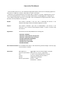
Related Documents
The related documents indicated in this publication may include preliminary versions.
However, preliminary versions are not marked as such.
Document Name
Document No.
CubeSuite
Start
Integrated Development Environment
Analysis
R20UT0265E
User's Manual
Programming
R20UT0266E
Caution
R20UT0256E
Message
R20UT0267E
Coding for CX compiler
R20UT0259E
Build for CX compiler
R20UT0261E
78K0 Coding
R20UT0004E
78K0 Build
R20UT0005E
78K0 Debug
R20UT0262E
78K0 Design
This manual
78K0R Coding
U19382E
78K0R Build
U19385E
78K0R Debug
R20UT0263E
78K0R Design
R20UT0007E
V850 Coding
U19383E
V850 Build
U19386E
V850 Debug
R20UT0264E
V850 Design
R20UT0257E
The related documents listed above are subject to change without
notice. Be sure to use the latest edition of each document when
designing.
All trademarks or registered trademarks in this document are the property of their respective
owners.
[MEMO]
[MEMO]
[MEMO]
TABLE OF CONTENTS
CHAPTER 1 GENERAL ... 10
1.1 Overview ... 10
1.2 Features ... 10
CHAPTER 2 FUNCTIONS (Pin Configurator) ... 11
2.1 Overview ... 11
2.2 Open Device Pin List Panel ... 13
2.2.1 Select item ... 14
2.2.2 Change display order ... 15
2.2.3 Add column ... 16
2.2.4 Delete column ... 17
2.3 Open Device Top View Panel ... 18
2.3.1 Select shape of microcontroller ... 19
2.3.2 Select color ... 20
2.3.3 Select popup information ... 21
2.3.4 Select additional information ... 22
2.4 Enter Information ... 23
2.5 Output Report Files ... 24
2.5.1 Output device pin list ... 24
2.5.2 Output device top view ... 25
CHAPTER 3 FUNCTIONS (Code Generator) ... 26
3.1 Overview ... 26
3.2 Open Code Generator Panel ... 27
3.3 Enter Information ... 28
3.3.1 Input rule ... 28
3.3.2 Icon indicating incorrect entry ... 29
3.3.3 Icon indicating pin conflict ... 30
3.4 Confirm Source Code ... 31
3.5 Output Source Code ... 32
3.5.1 Setting that determines whether or not to generate source code ... 33
3.5.2 Change file name ... 34
3.5.3 Change API function name ... 35
3.5.4 Change output mode ... 36
3.5.5 Change output destination folder ... 37
3.6 Output Report Files ... 38
3.6.1 Change output format ... 40
3.6.2 Change output destination ... 41
APPENDIX A WINDOW REFERENCE ... 42
A.1 Description ... 42
APPENDIX B OUTPUT FILES ... 103
B.1 Overview ... 103
B.2 Output File ... 103
APPENDIX C API FUNCTIONS ... 108
C.1 Overview ... 108
C.2 Output Function ... 108
C.3 Function Reference ... 114
C.3.1 System ... 116
C.3.2 Port ... 127
C.3.3 INT ... 134
C.3.4 Serial ... 145
C.3.5 Operational Amplifier ... 185
C.3.6 Comparator ... 195
C.3.7 A/D ... 200
C.3.8 Timer ... 210
C.3.9 Watchdog Timer ... 241
C.3.10 RTC ... 243
C.3.11 Clock Output ... 277
C.3.12 LVI ... 283
APPENDIX D INDEX ... 291
CubeSuite Ver.1.40
CHAPTER 1 GENERAL
CHAPTER 1 GENERAL
CubeSuite is an integrated development environment used to carry out tasks such as design, coding, build and debug
for developing application systems.
This chapter gives an overview of the design tool (Pin Configurator/Code Generator).
1.1
Overview
The design tool, which is one of the components provided by CubeSuite, enables you to output the pin assignment of
the microcontroller (device pin list and device top view), and the source code (device driver programs, C source files and
header files) necessary to control the peripheral functions provided by the microcontroller (clock generator, port functions,
etc.) by configuring various information using the GUI.
1.2
Features
The design tool (Pin Configurator/Code Generator) has the following features.
- Code generating function
The Code Generator can output not only device driver programs in accordance with the information configured
using the GUI, but also a build environment such as sample programs containing main functions and link directive
files.
Source code output by Code Generator conforms to the MISRA-C (Guidelines for the Use of the C Language in
Vehicle Based Software) coding convention.
- Reporting function
You can output configured information using Pin Configurator/Code Generator as files in various formats for use as
design documents.
- Renaming function
The user can change default names assigned to the files output by Code Generator and the API functions contained in the source code.
R20UT0006JJ0100 Rev.1.00
Sep 01, 2010
Page 10 of 300
CubeSuite Ver.1.40
CHAPTER 2 FUNCTIONS (Pin Configurator)
CHAPTER 2 FUNCTIONS (Pin Configurator)
This chapter describes the key functions provided by the design tool (Pin Configurator) along with operation procedures.
2.1
Overview
The Pin Configurator is used to output report files such as a device pin list and a device top view by entering pin assignment information of the microcontroller.
The following sections describe the operation procedures for Pin Configurator.
(1) Start CubeSuite
Launch CubeSuite from the [Start] menu of Windows.
Remark
See "CubeSuite Start User's Manual" for details on "Start CubeSuite".
(2) Create/Open project
Create a new project (that defines a kind of project, microcontroller to be used, build tools to be used, etc.) or load
an existing project.
Remark
See "CubeSuite Start User's Manual" for details on "Create/Open project".
(3) Open Device Pin List Panel
Open the Device Pin List panel, where you enter information on the pins of the microcontroller.
(a) Select item
Allows you to select items displayed in the device pin list.
(b) Change display order
Allows you to change the order in which items are displayed in the device pin list.
(c) Add column
Allows you to add columns to the device pin list.
(d) Delete column
Allows you to delete columns from the device pin list.
(4) Open Device Top View Panel
Open the Device Top View panel, where you can confirm the information entered for the pins.
(a) Select shape of microcontroller
Allows you to select the shape of the microcontroller displayed in the Device Top View panel.
(b) Select color
Allows you to select colors used to distinguish the type of pins (power pins, special pins, used pins, etc.)
whose information is displayed in the Device Top View panel.
R20UT0006JJ0100 Rev.1.00
Sep 01, 2010
Page 11 of 300
CubeSuite Ver.1.40
CHAPTER 2 FUNCTIONS (Pin Configurator)
(c) Select popup information
Allows you to select the type of information that popups when you move the mouse cursor over each pin in the
Device Top View panel.
(d) Select additional information
Select the type of information to display in Pin area of the Device Top View panel.
(5) Enter Information
Enter information on the pins of the microcontroller in the Device Pin List panel.
(6) Output Report Files
Output report files (files containing configured information using Pin Configurator: device pin list and device top
view) to the specified folder.
(a) Output device pin list
Output a device pin list.
(b) Output device top view
Output a device top view.
(7) Save project
Save a project.
Remark
See "CubeSuite Start User's Manual" for details on "Save project".
R20UT0006JJ0100 Rev.1.00
Sep 01, 2010
Page 12 of 300
CubeSuite Ver.1.40
2.2
CHAPTER 2 FUNCTIONS (Pin Configurator)
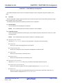
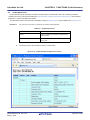
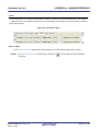
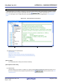
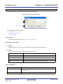
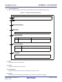
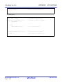
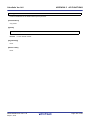
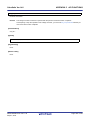
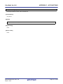
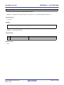
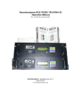
Open Device Pin List Panel
Open the Device Pin List panel, where you enter information on the pins of the microcontroller.
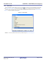
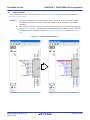
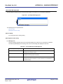
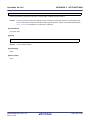
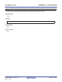
To open the Device Pin List panel, select [Project name (Project)] >> [Pin Configurator (Design Tool)] >> [Device Pin
List] in the Project Tree panel.
Figure 2-1. Open Device Pin List Panel
Remarks 1.
If an unsupported microcontroller is defined in the project for Pin Configurator, then "[Pin Configurator
(Design Tool)] node" will hide under [Project name (Project)] in the Project Tree panel.
2.
The Device Pin List panel consists of three tabs. Selecting one of the tabs changes the order in which
"information on each pin of the microcontroller" is displayed.
- [Pin Number] tab
Information on each pin of the microcontroller is displayed in the order of pin number.
- [Macro] tab
Information on each pin of the microcontroller is displayed in the order it was grouped into peripheral
functions.
- [External Peripheral] tab
Information about the pins connected to external peripherals is displayed in order grouped at the
external-peripheral component level.
R20UT0006JJ0100 Rev.1.00
Sep 01, 2010
Page 13 of 300
CubeSuite Ver.1.40
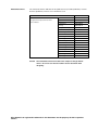
2.2.1
CHAPTER 2 FUNCTIONS (Pin Configurator)
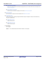
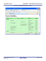
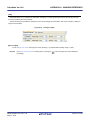
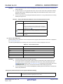
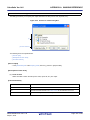
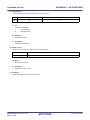
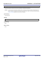
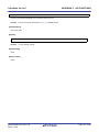
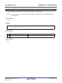
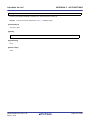
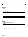
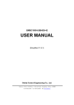
Select item
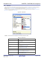
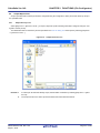
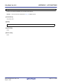
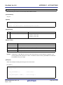
The Pin Configurator is used to select items to be displayed in the device pin list using the
button in the upper left
corner of the device pin list.
To select the item to be displayed, use the Column Chooser dialog box that opens by pressing the
button in the
upper left corner of the device pin list.
Figure 2-2. Select Item
Remark
To select the item to be displayed, check the check box that corresponds to the item.
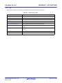
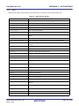
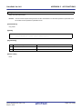
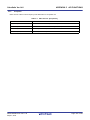
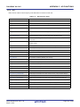
Table 2-1. Select Item
Checked
Displays the selected item in the device pin list.
Not checked
Hides the selected item in the device pin list.
R20UT0006JJ0100 Rev.1.00
Sep 01, 2010
Page 14 of 300
CubeSuite Ver.1.40
2.2.2
CHAPTER 2 FUNCTIONS (Pin Configurator)
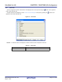
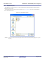
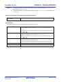
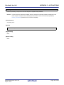
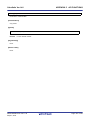
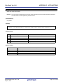
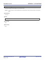
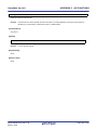
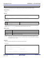
Change display order
In Pin Configurator, you can change the display order of columns in the device pin list (move columns) by dragging and
dropping columns.
Figure 2-3. Change Display Order
R20UT0006JJ0100 Rev.1.00
Sep 01, 2010
Page 15 of 300
CubeSuite Ver.1.40
Remark
CHAPTER 2 FUNCTIONS (Pin Configurator)
To change the display order, click the
button in the upper left of the device pin list. The Column Chooser
dialog box opens. Drag an item displayed in the dialog's select Items to display area, and drop it to the
desired destination in the device pin list. This will change the display order.
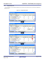
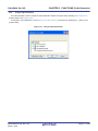
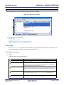
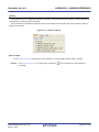
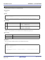
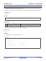
2.2.3
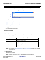
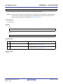
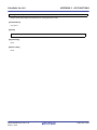
Add column
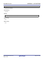
The Pin Configurator is used to add the "user's own column" to the device pin list using the [New Column] button in the
Column Chooser dialog box that opens by pressing the
button in the upper left corner of the device pin list.
To add a column, use the New Column dialog box that opens by pressing the [New Column] button in the Column
Chooser dialog box.
Figure 2-4. Add Column
Remark
On the device pin list, adding columns to the first level of [Macro] tab, [External Peripheral] tab is restricted.
R20UT0006JJ0100 Rev.1.00
Sep 01, 2010
Page 16 of 300
CubeSuite Ver.1.40
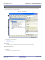
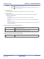
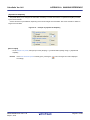
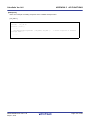
2.2.4
CHAPTER 2 FUNCTIONS (Pin Configurator)
Delete column
The Pin Configurator is used to delete the "user's own column" from the device pin list using the [Delete Column] button
in the Column Chooser dialog box that opens by pressing the
button in the upper left corner of the device pin list.
To delete a column, select the column you want to delete in the displayed item selection area of the Column Chooser
dialog box, and press the [Delete Column] button.
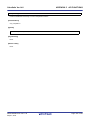
Figure 2-5. Delete Column
Remark
You can only delete the column which you added using the New Column dialog box.
R20UT0006JJ0100 Rev.1.00
Sep 01, 2010
Page 17 of 300
CubeSuite Ver.1.40
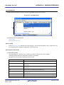
2.3
CHAPTER 2 FUNCTIONS (Pin Configurator)
Open Device Top View Panel
Open the Device Top View panel, where you can confirm the information entered for the pins of the microcontroller.
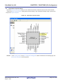
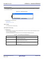
To open the Device Top View panel, select [Project name (Project)] >> [Pin Configurator (Design Tool)] >> [Device Top
View] in the Project Tree panel.
Figure 2-6. Open Device Top View Panel
Remark
In the Property panel, on the [Pin Configurator Settings] tab, if "BGA" is selected for the Package type, then
Device Top View panel cannot be opened.
R20UT0006JJ0100 Rev.1.00
Sep 01, 2010
Page 18 of 300
CubeSuite Ver.1.40
2.3.1
CHAPTER 2 FUNCTIONS (Pin Configurator)
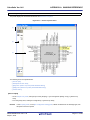
Select shape of microcontroller
Select the shape of the microcontroller displayed in the Device Top View panel which is opened as described in "2.3
Open Device Top View Panel".
To select the shape of the microcontroller, click [Pin Configurator Settings] tab >> [Package type] in the Property panel
and select the desired shape.
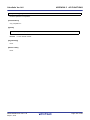
Figure 2-7. Select Shape of Microcontroller
Remark
Selection of the shape of the microcontroller is made using the order name (such as GC and GF).
R20UT0006JJ0100 Rev.1.00
Sep 01, 2010
Page 19 of 300
CubeSuite Ver.1.40
2.3.2
CHAPTER 2 FUNCTIONS (Pin Configurator)
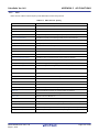
Select color
Select the colors used to distinguish the type of pins (power pins, special pins, unused pins, etc.) whose information is
displayed in the Device Top View panel which is opened as described in "2.3 Open Device Top View Panel".
To select the color to be displayed, select the desired color in the color palette that opens by clicking [Device Top View
Settings] tab >> [Color] in the Property panel.
Figure 2-8. Select Color
Remark
Select the colors to be displayed for the following eight types of items.
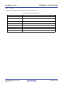
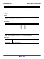
Table 2-2. Select Color
Item
Power pins
Outline
Selects the display color for power pins (pins whose use is
limited to power).
Special pins
Selects the display color for special pins (pins with specified
uses).
Unused pins
Selects the display color for unused pins (dual-use pins with no
use set in the Device Pin List panel).
Used pins
Selects the display color for used pins (dual-use pins with a use
set in the Device Pin List panel).
Device
Selects the display color of the microcontroller.
Highlight
Selects the background color of a pin selected in the Device
Pin List panel, on the [Pin Number] tab.
Macro highlight
Selects the background color of pins selected in the Device Pin
List panel, on the [Macro] tab.
R20UT0006JJ0100 Rev.1.00
Sep 01, 2010
Page 20 of 300
CubeSuite Ver.1.40
CHAPTER 2 FUNCTIONS (Pin Configurator)
Item
Outline
External peripheral highlight
Selects the background color of pins selected in the Device Pin
List panel, on the [External Peripheral] tab.
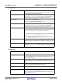
2.3.3
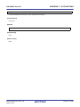
Select popup information
Select the type of information that popups when you move the mouse cursor over each pin in the Device Top View
panel which is opened as described in "2.3 Open Device Top View Panel".
To select the popup information, click [Device Top View Settings] tab >> [Tool tip] in the Property panel and select the
desired type of information.
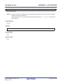
Figure 2-9. Select Popup Information
Remark
Popup information is selected from the following four types.
Table 2-3. Select Popup Information
Popup Information
Display all
Outline
Displays the "Description", "Recommend Connection For
Unused", and "Attention" strings for the device pin list.
Description / recommended con-
Displays the "Description", and "Recommend Connection For
nection for unused pin only
Unused" string for the device pin list.
Attention only
Displays the "Attention" string for the device pin list.
Not display
Hides tooltips when the mouse cursor hovers over a pin.
R20UT0006JJ0100 Rev.1.00
Sep 01, 2010
Page 21 of 300
CubeSuite Ver.1.40
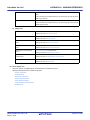
2.3.4
CHAPTER 2 FUNCTIONS (Pin Configurator)
Select additional information
Select the type of information to display in Pin area, in the Device Top View panel opened in "2.3 Open Device Top
View Panel".
Note that additional information is selected from the Property panel, on the [Device Top View Settings] tab, by selecting
the corresponding information under [Pin Name Display].
Figure 2-10. Select Additional Information
Remarks 1.
Select one of the following two types for Define name (whether to display the "Define Name" string of
the Device Pin List in appended format).
Display
Displays the "Define Name" string of the device pin list in appended
format.
Not display
2.
Hides the "Define Name" string of the device pin list.
Select one of the following two types for Pin function (whether to display it whether or not a function is
selected for "Function" on the Device Pin List).
Display all
Displays functions selected via the device pin list's "Function" feature in
parentheses.
Selected function only
Only display functions selected via the device pin list's "Function"
feature in the device top view.
R20UT0006JJ0100 Rev.1.00
Sep 01, 2010
Page 22 of 300
CubeSuite Ver.1.40
2.4
CHAPTER 2 FUNCTIONS (Pin Configurator)
Enter Information
Enter information on the pins of the microcontroller in the Device Pin List panel which is opened as described in "2.2
Open Device Pin List Panel".
Remarks 1.
You cannot add information in the "Pin Number" column, "Pin Name" column, "Description" column,
"Recommend Connection For Unused" column and "Attention" column because they contain fixed
information.
2.
If the "Free" in the "Function" column is changed to a specific pin name, color of the corresponding pin
in the Device Top View panel changes from the "color representing the unused pins" to the "color representing the used pins" selected by clicking [Device Top View Settings] tab >> [Color] in the Property
panel.
Figure 2-11. Change in Displayed Color
R20UT0006JJ0100 Rev.1.00
Sep 01, 2010
Page 23 of 300
CubeSuite Ver.1.40
2.5
CHAPTER 2 FUNCTIONS (Pin Configurator)
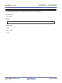
Output Report Files
Output report files (files containing information configured using Pin Configurator: device pin list and device top view) to
the specified folder.
2.5.1
Output device pin list
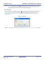
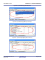
Select [File] menu >> [Save Pin List As...] to output a report file (a file containing information configured using Pin Configurator: device pin list).
The destination folder for the device pin list is specified in the Save As dialog box which opens by selecting [File] menu
>> [Save Pin List As ...].
Figure 2-12. Output Device Pin List
Remarks 1.
If a device pin list has been already output, that list will be overwritten by selecting [File] menu >> [Save
Pin List].
2.
The output format for the device pin list is limited to Microsoft Office Excel Book.
R20UT0006JJ0100 Rev.1.00
Sep 01, 2010
Page 24 of 300
CubeSuite Ver.1.40
2.5.2
CHAPTER 2 FUNCTIONS (Pin Configurator)
Output device top view
Select [File] menu >> [Save Top View As...] to output a report file (a file containing information configured using Pin
Configurator: device top view).
The destination folder for the device top view is specified in the Save As dialog box which opens by selecting [File]
menu >> [Save Top View As ...].
Figure 2-13. Output Device Top View
Remark
If a device top view has been already output, that view will be overwritten by selecting [File] menu >> [Save
Top View].
R20UT0006JJ0100 Rev.1.00
Sep 01, 2010
Page 25 of 300
CubeSuite Ver.1.40
CHAPTER 3 FUNCTIONS (Code Generator)
CHAPTER 3 FUNCTIONS (Code Generator)
This chapter describes the key functions provided by the design tool (Code Generator) along with operation procedures.
3.1
Overview
The Code Generator outputs source code (device driver programs) based on information selected/entered on CubeSuite panels that is needed to control peripheral functions provided by the microcontroller (clock generator, port functions,
etc.).
The following sections describe the operation procedures for Code Generator.
(1) Start CubeSuite
Launch CubeSuite from the [Start] menu of Windows.
Remark
See "CubeSuite Start User's Manual" for details on "Start CubeSuite".
(2) Create/Open project
Create a new project (that defines a kind of project, microcontroller to be used, build tools to be used, etc.) or load
an existing project.
Remark
See "CubeSuite Start User's Manual" for details on "Create/Open project".
(3) Open Code Generator Panel
Open the Code Generator panel used to configure the information necessary to control the peripheral functions
(clock generator, port functions, etc.).
(4) Enter Information
Configure the information necessary to control the peripheral functions in the Code Generator panel.
(5) Confirm Source Code
Confirm the source code (device driver program) that reflects the information configured in the Code Generator
panel.
(6) Output Source Code
Output the source code (device driver program) to the specified folder.
(7) Output Report Files
Output report files (a file containing information configured using Code Generator and a file containing information
regarding the source code) to the specified folder.
(8) Save project
Save a project.
Remark
See "CubeSuite Start User's Manual" for details on "Save project".
R20UT0006JJ0100 Rev.1.00
Sep 01, 2010
Page 26 of 300
CubeSuite Ver.1.40
3.2
CHAPTER 3 FUNCTIONS (Code Generator)
Open Code Generator Panel
Open the Code Generator panel to configure the information necessary to control the peripheral functions (clock generator, port functions, etc.).
To open the Code Generator panel, select [Project name (Project)] >> [Code Generator (Design Tool)] >> Peripheral
function node "[System], [Port], etc." in the Project Tree panel.
Figure 3-1. Open Code Generator Panel
Remark
If an unsupported microcontroller is defined in the project for Code Generator, then "[Code Generator
(Design Tool)] node" will hide under [Project name (Project)] in the Project Tree panel.
R20UT0006JJ0100 Rev.1.00
Sep 01, 2010
Page 27 of 300
CubeSuite Ver.1.40
3.3
CHAPTER 3 FUNCTIONS (Code Generator)
Enter Information
Configure the information necessary to control the peripheral functions in the information setting area of the Code Generator panel which is opened as described in "3.2 Open Code Generator Panel".
Remark
When controlling multiple peripheral functions, repeat the procedures described in "3.2 Open Code Generator Panel" through "3.3 Enter Information".
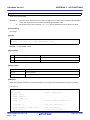
3.3.1
Input rule
Following is the rules for input to the Code Generator panel.
(1) Character set
Character sets that are allowed to input are as follows.
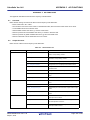
Table 3-1. List of Character Set
Character Set
ASCII
Outline
1-byte alphabet, number, symbol
Shift-JIS
2-byte alphabet, number, symbol, Hiragana, Katakana, Kanji and 1-byte Katakana
EUC-JP
2-byte alphabet, number, symbol, Hiragana, Katakana, Kanji and 1-byte Katakana
UTF-8
2-byte alphabet, number, symbol, Hiragana, Katakana, Kanji (include Chinese
character) and 1-byte Katakana
(2) Number
Notations allowed when entering numbers are as follows.
Table 3-2. List of Notation
Notation
Decimal number
Outline
A numeric value that starts with a number between 1 and 9 and followed by
numbers between 0 and 9, and the numeric value 0
Hex number
A numeric value that starts with 0x and followed by a combination of numbers
from 0 to 9 and characters from A to F (characters are not case sensitive)
R20UT0006JJ0100 Rev.1.00
Sep 01, 2010
Page 28 of 300
CubeSuite Ver.1.40
3.3.2
CHAPTER 3 FUNCTIONS (Code Generator)
Icon indicating incorrect entry
When performing code generation, if you enter an invalid string in the Code Generator panel, or a required input is
missing, then a
icon displays next to the incorrect input, and the text is displayed in red to warn that there is a problem
with the input.
Remark
If the mouse cursor is moved over the
icon, information regarding the string that should be entered (tips
for correcting the entry) popups.
Figure 3-2. Icon Indicating Incorrect Entry
R20UT0006JJ0100 Rev.1.00
Sep 01, 2010
Page 29 of 300
CubeSuite Ver.1.40
3.3.3
CHAPTER 3 FUNCTIONS (Code Generator)
Icon indicating pin conflict
If a conflict occurs between the pins while setting various peripheral functions in the Code Generator panel, the
icon is displayed at the location where the conflict occurs to warn the user of a conflict between the pins.
Remark
If the mouse cursor is moved over the
icon, information regarding the conflict between the pins (tips for
avoiding the conflict) popups.
Figure 3-3. Icon Indicating Pin Conflict
R20UT0006JJ0100 Rev.1.00
Sep 01, 2010
Page 30 of 300
CubeSuite Ver.1.40
3.4
CHAPTER 3 FUNCTIONS (Code Generator)
Confirm Source Code
Confirm the source code (device driver program) that reflects the information configured as described in "3.3 Enter
Information".
To confirm the source code, use the Code Generator Preview panel that opens by selecting [View] menu >> [Code
Generator Preview].
Figure 3-4. Confirm Source Code
Remarks 1.
You can change the source code to be displayed by selecting the source file name or API function
name in the Code Generator Preview panel.
2.
The following table displays the meaning of the color of the source code text displayed in the Code
Generator Preview panel.
Table 3-3. Color of Source Code
Color
Outline
Green
Comment
Blue
Reserved word for C compiler
Red
Numeric value
Black
Code section
Gray
File name
3.
You cannot edit the source code within the Code Generator Preview panel.
4.
For some of the API functions (such as API functions for serial array units), values such as the SFR
register value are calculated and finalized when the source code is generated (when the
button on the Code Generator panel is pressed). For this reason, the source
code displayed in the Code Generator Preview panel may not be the same as that would actually be
generated.
R20UT0006JJ0100 Rev.1.00
Sep 01, 2010
Page 31 of 300
CubeSuite Ver.1.40
3.5
CHAPTER 3 FUNCTIONS (Code Generator)
Output Source Code
Output the source code (device driver program) by pressing the
button on the Code Generator
panel.
The destination folder for the source code is specified by clicking [Generation] tab >> [Output folder] in the Property
panel.
Figure 3-5. Output Source Code
Remark
In order to both output source files and add them to the project (display the corresponding source file names
in the Project Tree panel) when you click the
button, you must open the Property
panel, and under [Generation] tab >> [Register files], specify "Output files to project".
Figure 3-6. Configure Whether to Register
R20UT0006JJ0100 Rev.1.00
Sep 01, 2010
Page 32 of 300
CubeSuite Ver.1.40
3.5.1
CHAPTER 3 FUNCTIONS (Code Generator)
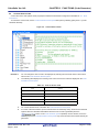
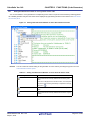
Setting that determines whether or not to generate source code
You can set whether or not to generate the corresponding source code on a per-API function basis by selecting [Generate code/Not generate code] from the context menu displayed by right clicking the API function name in the Code Generator Preview panel.
Figure 3-7. Setting That Determines Whether or Not to Generate Source Code
Remark
You can confirm the current setting for the generation of source code by checking the type of icon in the
Code Generator Preview panel.
Table 3-4. Setting That Determines Whether or Not to Generate Source Code
Type of Icon
Outline
Source code for the currently selected API function is generated.
If this icon is displayed next to the API function, the corresponding source code must be generated (it is impossible to change
the icon to
).
Source code for the currently selected API function is generated.
Source code for the currently selected API function is not generated.
R20UT0006JJ0100 Rev.1.00
Sep 01, 2010
Page 33 of 300
CubeSuite Ver.1.40
3.5.2
CHAPTER 3 FUNCTIONS (Code Generator)
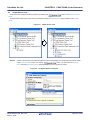
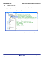
Change file name
The Code Generator is used to change the file name by selecting [Rename] from the context menu displayed by right
clicking the file name in the Code Generator Preview panel.
Figure 3-8. Change File Name
Remark
To restore the default file name defined by Code Generator, select [Default] from the context menu.
R20UT0006JJ0100 Rev.1.00
Sep 01, 2010
Page 34 of 300
CubeSuite Ver.1.40
3.5.3
CHAPTER 3 FUNCTIONS (Code Generator)
Change API function name
The Code Generator is used to change the name of the API function by selecting [Rename] from the context menu displayed by right clicking the API function name in the Code Generator Preview panel.
Figure 3-9. Change API Function Name
Remark
To restore the default name of the API function defined by Code Generator, select [Default] from the context
menu.
R20UT0006JJ0100 Rev.1.00
Sep 01, 2010
Page 35 of 300
CubeSuite Ver.1.40
3.5.4
CHAPTER 3 FUNCTIONS (Code Generator)
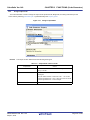
Change output mode
The Code Generator is used to change the output mode (Overwrite file, Merge file, Do nothing if file exists) for the
source code by selecting [Generation] tab >> [Generate file] in the Property panel.
Figure 3-10. Change Output Mode
Remark
The output mode is selected from the following three types.
Table 3-5. Output Mode of Source Code
Output Mode
Overwrite file
Outline
If a file with the same name exists, the existing file is overwritten by a new file.
Merge file
If a file with the same name exists, a new file is merged with the
existing file.
Only the section between "/* Start user code ... . Do not edit
comment generated here */" and "/* End user code. Do not edit
comment generated here */" will be merged.
Do nothin if file exists
R20UT0006JJ0100 Rev.1.00
Sep 01, 2010
If a file with the same name exists, a new file will not be output.
Page 36 of 300
CubeSuite Ver.1.40
3.5.5
CHAPTER 3 FUNCTIONS (Code Generator)
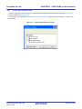
Change output destination folder
The Code Generator is used to change the output destination folder for the source code by selecting [Generation] tab
>> [Output folder] in the Property panel.
To change the output destination, use the Browse For Folder dialog box which opens by pressing the [...] button in the
[Output folder].
Figure 3-11. Change Output Destination Folder
R20UT0006JJ0100 Rev.1.00
Sep 01, 2010
Page 37 of 300
CubeSuite Ver.1.40
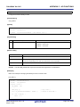
3.6
CHAPTER 3 FUNCTIONS (Code Generator)
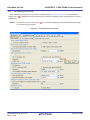
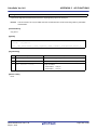
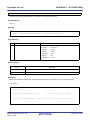
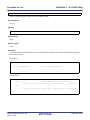
Output Report Files
Output report files (a file containing information configured using Code Generator and a file containing information
regarding the source code) by first activating the Code Generator panel or Code Generator Preview panel, then selecting
[File] menu >> [Save Code Generator Report].
The destination folder for the report file is specified by clicking [Generation] tab >> [Output folder] in the Property panel.
Remarks 1.
You can only use "macro" or "function" as a name of the report file.
Table 3-6. Output Report Files
File Name
macro
Outline
A file that contains the information configured using
Code Generator
function
A file that contains the information regarding the
source code
2.
The output mode for the report file is fixed to "Overwrite file".
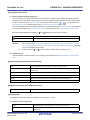
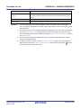
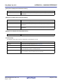
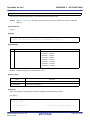
Figure 3-12. Output Example of Report File "macro"
R20UT0006JJ0100 Rev.1.00
Sep 01, 2010
Page 38 of 300
CubeSuite Ver.1.40
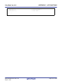
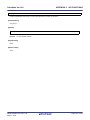
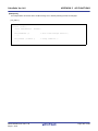
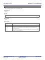
CHAPTER 3 FUNCTIONS (Code Generator)
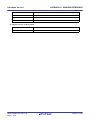
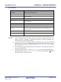
Figure 3-13. Output Example of Report File "function"
R20UT0006JJ0100 Rev.1.00
Sep 01, 2010
Page 39 of 300
CubeSuite Ver.1.40
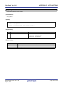
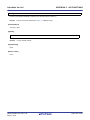
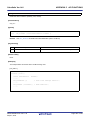
3.6.1
CHAPTER 3 FUNCTIONS (Code Generator)
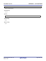
Change output format
The Code Generator is used to change the output format (HTML file or CSV file) of the report file by selecting [Generation] tab >> [Report type] in the Property panel.
Figure 3-14. Change Output Format
Remark
Output format is selected from the following two types.
Table 3-7. Output Mode of Source Code
Report Type
Outline
HTML file
Outputs a report file in HTML format.
CSV file
Outputs a report file in CSV format.
R20UT0006JJ0100 Rev.1.00
Sep 01, 2010
Page 40 of 300
CubeSuite Ver.1.40
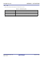
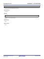
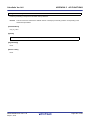
3.6.2
CHAPTER 3 FUNCTIONS (Code Generator)
Change output destination
The Code Generator is used to change the output destination folder for the report file by selecting [Generation] tab >>
[Output folder] in the Property panel.
To change the output destination, use the Browse For Folder dialog box which opens by pressing the [...] button in the
[Output folder].
Figure 3-15. Change Output Destination
R20UT0006JJ0100 Rev.1.00
Sep 01, 2010
Page 41 of 300
CubeSuite Ver.1.40
APPENDIX A WINDOW REFERENCE
APPENDIX A WINDOW REFERENCE
This appendix explains in detail the functions of the windows, panels and dialog boxes of the design tool.
A.1
Description
The design tool has the following windows, panels and dialog boxes.
Table A-1. Window/Panel/Dialog Box List
Window/Panel/Dialog Box Name
Main window
Function
This is the first window to open when CubeSuite is launched. This window is used to
operate various components (design tool, build tool, etc.) provided by CubeSuite.
Project Tree panel
This panel displays the components of the project (microcontroller, design tool, build
tool, etc.) in a tree structure.
Property panel
This panel allows you to view the information and change the setting for the node
selected in the Project Tree panel, the peripheral function button pressed in the Code
Generator panel or the file selected in the Code Generator Preview panel.
Device Pin List panel
This panel allows you to enter information on each pin of the microcontroller.
Device Top View panel
This panel displays the information entered in the Device Pin List panel.
Code Generator panel
This panel allows you to configure the information necessary to control the peripheral
functions provided by the microcontroller.
Code Generator Preview panel
This panel allows you to confirm or configure on a per-API function basis the setting
that determines whether or not the source code (device driver program) is generated
when the
button is pressed in the Code Generator panel. It also
allows you to confirm the source code that reflects the information configured in the
Code Generator panel.
Output panel
This panel displays operation logs for various components (design tool, build tool, etc.)
provided by CubeSuite.
Column Chooser dialog box
This dialog box allows you to choose whether or not to display the item listed in this
dialog box in the device pin list, and add columns to or delete columns from the device
pin list.
New Column dialog box
This dialog box allows you to add your own column to the device pin list.
Browse For Folder dialog box
This dialog box allows you to specify the output destination for files (source code,
report file, etc.).
Save As dialog box
R20UT0006EJ0100 Rev.1.00
Sep 01, 2010
This dialog box allows you to name and save a file (such as a report file).
Page 42 of 300
CubeSuite Ver.1.40
APPENDIX A WINDOW REFERENCE
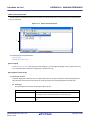
Main window
This is the first window to open when CubeSuite is launched. This window is used to operate various components
(design tool, build tool, etc.) provided by CubeSuite.
Figure A-1. Main Window
(1)
(2)
The following items are explained here.
- [How to open]
- [Description of each area]
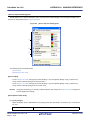
[How to open]
- From the [start] menu, select [All Programs] >> [NEC Electronics CubeSuite] >>[CubeSuite].
[Description of each area]
(1) Menu bar
This area consists of the following menu items.
R20UT0006EJ0100 Rev.1.00
Sep 01, 2010
Page 43 of 300
CubeSuite Ver.1.40
APPENDIX A WINDOW REFERENCE
(a) [File] menu
Save Pin List
Device Pin List panel-dedicated item
Saves a report file (a file containing information configured using Pin Configurator: device pin list) overwriting the existing file.
Save Pin List As...
Device Pin List panel-dedicated item
Opens the Save As dialog box for naming and saving a report file (a file containing information configured using Pin Configurator: device pin list).
Save Top View
Device Top View panel-dedicated item
Saves a report file (a file containing information configured using Pin Configurator: device top view) overwriting the existing file.
Save Top View As...
Device Top View panel-dedicated item
Opens the Save As dialog box for naming and saving a report file (a file containing information configured using Pin Configurator: device top view).
Save Code Generator Report
Code Generator panel/Code Generator Preview panel-dedicated item
Outputs report files (a file containing information configured using Code Generator and a file containing information regarding the source code).
- The output format for the report file (either HTML or CSV) is selected by clicking [Generation] tab >> [Report type] in the Property panel.
- The destination folder for the report file is specified by clicking [Generation]
tab >> [Output folder] in the Property panel.
Save Output-Tab Name
Output panel-dedicated item
Saves the message corresponding to the specified tab overwriting the existing
file.
Save Output-Tab Name As...
Output panel-dedicated item
Opens the Save As dialog box for naming and saving the message corresponding to the specified tab.
(b) [Edit] menu
Undo
Property panel-dedicated item
Cancels the effect of an edit operation to restore the previous state.
Cut
Property panel-dedicated item
Sends the character string or lines selected with range selection to the clipboard and deletes them.
Copy
Property panel/Output panel-dedicated item
Sends the character string or lines selected with range selection to the clipboard.
Paste
Property panel-dedicated item
Inserts the contents of the clipboard at the caret position.
Delete
Property panel-dedicated item
Deletes the character string or the lines selected with the range selection.
Select All
Property panel/Output panel-dedicated item
Selects all the strings displayed in the item being edited or all the strings displayed in the Message area.
R20UT0006EJ0100 Rev.1.00
Sep 01, 2010
Page 44 of 300
CubeSuite Ver.1.40
Search...
APPENDIX A WINDOW REFERENCE
Device Pin List panel/Code Generator Preview panel/Output panel-dedicated
item
Opens the Search and Replace dialog box for searching strings with the [Quick
Search] tab selected.
Replace...
Output panel-dedicated item
Opens the Search and Replace dialog box for replacing strings with the [Whole
Replace] tab selected.
(c) [Help] menu
Open Help for Project Tree Panel
Project Tree panel-dedicated item
Displays the help of Project Tree panel.
Open Help for Property Panel
Property panel-dedicated item
Displays the help of Property panel.
Open Help for Device Pin List
Device Pin List panel-dedicated item
Panel
Displays the help of Device Pin List panel.
Open Help for Device Top View
Device Top View panel-dedicated item
Panel
Displays the help of Device Top View panel.
Open Help for Code Generator
Code Generator panel-dedicated item
Panel
Displays the help of Code Generator panel.
Open Help for Code Generator
Code Generator Preview panel-dedicated item
Preview Panel
Displays the help of Code Generator Preview panel.
Open Help for Output Panel
Output panel-dedicated item
Displays the help of Output panel.
(2) Panel display area
This area consists of multiple panels, each dedicated to a different purpose.
See the following sections for details on this area.
- Project Tree panel
- Property panel
- Device Pin List panel
- Device Top View panel
- Code Generator panel
- Code Generator Preview panel
- Output panel
R20UT0006EJ0100 Rev.1.00
Sep 01, 2010
Page 45 of 300
CubeSuite Ver.1.40
APPENDIX A WINDOW REFERENCE
Project Tree panel
This panel displays components of the project (microcontroller, design tool, build tool, etc.) in a tree structure.
Figure A-2. Project Tree Panel
(1)
The following items are explained here.
- [How to open]
- [Description of each area]
- [[Help] menu (Project Tree panel-dedicated items)]
- [Context menu]
[How to open]
- From the [View] menu, select [Project Tree].
[Description of each area]
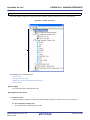
(1) Project tree area
This area displays components of the project (microcontroller, design tool, build tool, etc.) in a tree structure.
(a) Pin Configurator (Design Tool)
This node consists of the following pin nodes.
R20UT0006EJ0100 Rev.1.00
Sep 01, 2010
Page 46 of 300
CubeSuite Ver.1.40
Device Pin List
APPENDIX A WINDOW REFERENCE
Opens the Device Pin List panel for entering information on the pins of the
microcontroller.
Device Top View
Opens the Device Top View panel that displays the information entered in the
Device Pin List panel.
(b) Code Generator (Design Tool)
This node consists of the following peripheral function nodes.
When there is peripheral function target microcontroller is not supporting, peripheral functionbutton is not
disokayed.
System
Opens the [System] for configuring the information necessary to control the
functions of clock generator, on-chip debug function and etc. provided by the
microcontroller.
Port
Opens the [Port] for configuring the information necessary to control the port
functions provided by the microcontroller.
INT
Opens the [INT] for configuring the information necessary to control the interrupt functions and the key interrupt function provided by the microcontroller.
Serial
Opens the [Serial] for configuring the information necessary to control the functions of serial array unit and functions of serial interface provided by the microcontroller.
Operational Amplifier
Opens the [Operational Amplifier] for configuring the information necessary to
control the functions of comparator/programmable gain amplifier provided by
the microcontroller.
Comparator
Opens the [Comparator] for configuring the information necessary to control the
functions of comparator provided by the microcontroller.
A/D
Opens the [A/D] for configuring the information necessary to control the function of A/D converter provided by the microcontroller.
Timer
Opens the [Timer] for configuring the information necessary to control the functions of timer array unit provided by the microcontroller.
Watchdog Timer
Opens the [Watchdog Timer] for configuring the information necessary to control the functions of watchdog timer provided by the microcontroller.
RTC
Opens the [RTC] for configuring the information necessary to control the functions of real-time counter provided by the microcontroller.
Clock Output
Opens the [Clock Output] for configuring the information necessary to control
the functions of clock output controller provided by the microcontroller.
LVI
Opens the [LVI] for configuring the information necessary to control the functions of low-voltage detector provided by the microcontroller.
(c) Icons
The table below displays the meaning of the icon displayed to the left of the string representing the peripheral
function node.
Operation in the corresponding Code Generator panel has been carried out.
Operation in the corresponding Code Generator panel has not been carried
out.
,
The problem occurs on the settings became the manipulation to the other
peripheral function node influences.
R20UT0006EJ0100 Rev.1.00
Sep 01, 2010
Page 47 of 300
CubeSuite Ver.1.40
APPENDIX A WINDOW REFERENCE
[[Help] menu (Project Tree panel-dedicated items)]
Open Help for Project Tree Panel
Displays the help of this panel.
[Context menu]
The following context menu items are displayed by right clicking the mouse.
Return to Reset Value
Property
Restores the information for the selected peripheral function node to its default state.
Opens the Property panel containing the information for the selected node ([Pin
Configurator (Design Tool)] or [Code Generator (Design Tool)]).
R20UT0006EJ0100 Rev.1.00
Sep 01, 2010
Page 48 of 300
CubeSuite Ver.1.40
APPENDIX A WINDOW REFERENCE
Property panel
This panel allows you to view the information on and change the setting for the node selected in the Project Tree panel,
the peripheral function button pressed in the Code Generator panel or the file selected in the Code Generator Preview
panel.
Figure A-3. Property Panel (Selected [Pin Configurator (Design Tool)])
(1)
(2)
The following items are explained here.
- [How to open]
- [Description of each area]
- [[Edit] menu (Property panel-dedicated items)]
- [[Help] menu (Property panel-dedicated items)]
- [Context menu]
[How to open]
- On the Project Tree panel, select a node ([Pin Configurator (Design Tool)], [Device Pin List], [Device Top View],
[Code Generator (Design Tool)], peripheral function node ”[System], [Port], etc.”), and then select [Property] from
the [View] menu.
- On the Project Tree panel, select a node ([Pin Configurator (Design Tool)], [Device Pin List], [Device Top View],
[Code Generator (Design Tool)], peripheral function node ”[System], [Port], etc.”), and then select [Property] from
the context menu.
- On the Code Generator Preview panel, select a file, and then select [Property] from the [View] menu.
- On the Code Generator Preview panel, select a file, and then select [Property] from the context menu.
Remarks 1.
If this panel is already open, selecting a different node ([Pin Configurator (Design Tool)], [Device Pin
List], [Device Top View], [Code Generator (Design Tool)] or peripheral function node "[System], [Port],
etc.") in the Project Tree panel changes the content displayed in the Detail information display/change
area and Explanation area accordingly.
2.
If this panel is already open, pressing a different peripheral function button "
,
, etc." in the
Code Generator panel changes the content displayed in the Detail information display/change area and
Explanation area accordingly.
3.
If this panel is already open, selecting a different file in the Code Generator Preview panel changes the
content displayed in the Detail information display/change area and Explanation area accordingly.
R20UT0006EJ0100 Rev.1.00
Sep 01, 2010
Page 49 of 300
CubeSuite Ver.1.40
APPENDIX A WINDOW REFERENCE
[Description of each area]
(1) Detail information display/change area
This area allows you to view the information on and change the setting for the node ([Pin Configurator (Design
Tool)], [Device Pin List], [Device Top View], [Code Generator (Design Tool)] or peripheral function node "[System],
[Port], etc.) selected in the Project Tree panel, the peripheral function button "
,
, etc." pressed in the
Code Generator panel, or the file selected in the Code Generator Preview panel.
The content displayed in this area differs depending on the node selected in the Project Tree panel, the peripheral
function button pressed in the Code Generator panel or the file selected in the Code Generator Preview panel.
The following table displays the meaning of
and
displayed to the left of each category.
Indicates that the items within the category are displayed as a "collapsed view".
Indicates that the items within the category are displayed as an "expanded view".
Remarks 1.
See the sections "[Pin Configurator Settings] tab", ”[Pin Configurator Information] tab”, "[Device
Top View Settings] tab", "[Generation] tab", "[Macro Setting] tab" and "[File Setting] tab" for details
on the content displayed in this area.
2.
To switch between
and
, click this mark or double-click the category name.
(2) Explanation area
This area displays a "brief description" of the category or item selected in the Detail information display/change
area.
[[Edit] menu (Property panel-dedicated items)]
Undo
Cut
Cancels the effect of an edit operation to restore the previous state.
Sends the character string or lines selected with range selection to the clipboard and
deletes them.
Copy
Sends the character string or lines selected with range selection to the clipboard.
Paste
Inserts the contents of the clipboard at the caret position.
Delete
Deletes the character string or the lines selected with the range selection.
Select All
Selects all strings displayed in the item being edited.
[[Help] menu (Property panel-dedicated items)]
Open Help for Property Panel
Displays the help of this panel.
[Context menu]
The following context menu items are displayed by right clicking the mouse.
(1) While the item is being edited
Undo
Cancels the effect of an edit operation to restore the previous state.
Cut
Sends the character string or lines selected with range selection to the clipboard and
deletes them.
R20UT0006EJ0100 Rev.1.00
Sep 01, 2010
Page 50 of 300
CubeSuite Ver.1.40
APPENDIX A WINDOW REFERENCE
Copy
Sends the character string or lines selected with range selection to the clipboard.
Paste
Inserts the contents of the clipboard at the caret position.
Delete
Deletes the character string or the lines selected with the range selection.
Select All
Selects all strings displayed in the item being edited.
(2) While the item is not being edited
Property Reset to Default
Restores the selected item to its default state.
Property Reset All to Default
Restores all items to their default state.
R20UT0006EJ0100 Rev.1.00
Sep 01, 2010
Page 51 of 300
CubeSuite Ver.1.40
APPENDIX A WINDOW REFERENCE
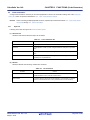
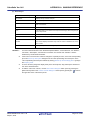
[Pin Configurator Settings] tab
This tab displays information (Product Information, Use of Pin Configurator Panels and Package) on the [Pin Configurator (Design Tool)] selected in the Project Tree panel.
Figure A-4. [Pin Configurator Settings] Tab
(1)
(2)
(3)
The following items are explained here.
- [How to open]
- [Description of each area]
[How to open]
- On the Project Tree panel, select [Project name (Project)] >> [Pin Configurator (Design Tool)], and then select
[Property] from the [View] menu.
- On the Project Tree panel, select [Project name (Project)] >> [Pin Configurator (Design Tool)], and then select
[Property] from the context menu.
Remark
If this panel is already open, selecting a different [Pin Configurator (Design Tool)] in the Project Tree panel
changes the content displayed accordingly.
[Description of each area]
(1) [Product Information] category
This area displays product information (Version and Release date) on Pin Configurator.
Version
Displays the version of Pin Configurator.
Release date
Displays the release date of Pin Configurator.
(2) [Use of Pin Configurator Panels] category
Select whether to show the Device Pin List panel and Device Top View panel.
R20UT0006EJ0100 Rev.1.00
Sep 01, 2010
Page 52 of 300
CubeSuite Ver.1.40
Use pin configurator panels
APPENDIX A WINDOW REFERENCE
Selects whether to display the Device Pin List panel and Device Top View panel in
the Main window the next time this project is opened.
Yes
Displays the Device Pin List panel and Device Top
View panel.
No
Hides the Device Pin List panel and Device Top View
panel.
(3) [Package] category
Change the shape (package type) and settings of the microcontroller to display as the device top view in the
Device Top View panel.
Package type
R20UT0006EJ0100 Rev.1.00
Sep 01, 2010
Selects the shape of the microcontroller displayed in the device top view.
Page 53 of 300
CubeSuite Ver.1.40
APPENDIX A WINDOW REFERENCE
[Pin Configurator Information] tab
This tab displays information (Product information) on the [Device Pin List] selected in the Project Tree panel.
Figure A-5. [Pin Configurator Information] Tab
(1)
The following items are explained here.
- [How to open]
- [Description of each area]
[How to open]
- On the Project Tree panel, select [Project name (Project)] >> [Pin Configurator (Design Tool)] >> [Device Pin List],
and then select [Property] from the [View] menu.
- On the Project Tree panel, select [Project name (Project)] >> [Pin Configurator (Design Tool)] >> [Device Pin List],
and then select [Property] from the context menu.
Remark
If this panel is already open, selecting a different [Device Pin List] in the Project Tree panel changes the
content displayed accordingly.
[Description of each area]
(1) [Product Information] category
This area displays product information (Version and Release date) on Pin Configurator.
Version
Displays the version of Pin Configurator.
Release date
Displays the release date of Pin Configurator.
R20UT0006EJ0100 Rev.1.00
Sep 01, 2010
Page 54 of 300
CubeSuite Ver.1.40
APPENDIX A WINDOW REFERENCE
[Device Top View Settings] tab
This tab allows you to view the information (Color, Tool Tip and Pin Name Display) on and change the setting for the
[Device Top View] selected in the Project Tree panel.
Figure A-6. [Device Top View Settings] Tab
(1)
(2)
(3)
The following items are explained here.
- [How to open]
- [Description of each area]
[How to open]
- On the Project Tree panel, select [Project name (Project)] >> [Pin Configurator (Design Tool)] >> [Device Top
View], and then select [Property] from the [View] menu.
- On the Project Tree panel, select [Project name (Project)] >> [Pin Configurator (Design Tool)] >> [Device Top
View], and then select [Property] from the context menu.
Remark
If this panel is already open, selecting a different [Device Top View] in the Project Tree panel changes the
content displayed accordingly.
[Description of each area]
(1) [Color] category
Select the display colors to differentiate the pin groups (power pins, special pins, unused pins, etc.) in the device
top view.
Power pins
R20UT0006EJ0100 Rev.1.00
Sep 01, 2010
Selects the display color for power pins (pins whose use is limited to power).
Page 55 of 300
CubeSuite Ver.1.40
APPENDIX A WINDOW REFERENCE
Special pins
Selects the display color for special pins (pins with specified uses).
Unused pins
Selects the display color for unused pins (dual-use pins with no use set in the
Device Pin List panel).
Used pins
Selects the display color for used pins (dual-use pins with a use set in the Device
Pin List panel).
Device
Selects the display color of the microcontroller.
Highlight
Selects the background color of a pin selected in the Device Pin List panel, on the
[Pin Number] tab.
Macro highlight
Selects the background color of pins selected in the Device Pin List panel, on the
[Macro] tab.
External peripheral highlight
Selects the background color of pins selected in the Device Pin List panel, on the
[External Peripheral] tab.
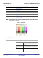
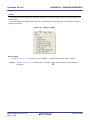
Remark
To change the setting of the color, use the following color palette which opens by making a selection
from the dropdown list in this area.
Figure A-7. Color Palette
(2) [Tool Tip] category
Select whether to display a tooltip with information about a pin when the mouse cursor is moved over the pin in the
device top view.
Tool tip
Selects whether to display a tooltip with information about a pin when the mouse
cursor is moved over the pin in the device top view panel.
Display all
Displays the "Description", "Recommend Connection
For Unused", and "Attention" strings for the device
pin list.
Description / recommended
Displays the "Description", and "Recommend
connection for unused pin
Connection For Unused" string for the device pin list.
only
Attention only
Not display
Displays the "Attention" string for the device pin list.
Hides tooltips when the mouse cursor hovers over a
pin.
R20UT0006EJ0100 Rev.1.00
Sep 01, 2010
Page 56 of 300
CubeSuite Ver.1.40
APPENDIX A WINDOW REFERENCE
(3) [Pin Name Display] category
Select whether to display additional information about the pin in the device top view.
Define name
Selects whether to display the "Define Name" string of the device pin list appended
to the pin in the device top view.
Display
Displays the "Define Name" string of the device pin
list in appended format.
Not display
Pin function
Hides the "Define Name" string of the device pin list.
Selects whether to also display unselected functions in the device top view when a
function has been selected from the device pin list's "Function" feature.
Display all
Displays functions selected via the device pin list's
"Function" feature in parentheses.
Selected function only
Only display functions selected via the device pin
list's "Function" feature in the device top view.
R20UT0006EJ0100 Rev.1.00
Sep 01, 2010
Page 57 of 300
CubeSuite Ver.1.40
APPENDIX A WINDOW REFERENCE
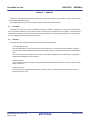
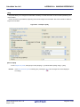
[Generation] tab
This tab allows you to view the information (Product Information, Generate File Mode and Pin Configurator Reflect
Mode) on and change the setting for the [Code Generator (Design Tool)] selected in the Project Tree panel.
Figure A-8. [Generation] Tab
(1)
(2)
(3)
The following items are explained here.
- [How to open]
- [Description of each area]
[How to open]
- On the Project Tree panel, select [Project name (Project)] >> [Code Generator (Design Tool)], and then select
[Property] from the [View] menu.
- On the Project Tree panel, select [Project name (Project)] >> [Code Generator (Design Tool)], and then select
[Property] from the context menu.
Remark
If this panel is already open, selecting a different [Code Generator (Design Tool)] in the Project Tree panel
changes the content displayed accordingly.
[Description of each area]
(1) [Product Information] category
This area displays product information (Version and Release date) on Code Generator.
R20UT0006EJ0100 Rev.1.00
Sep 01, 2010
Page 58 of 300
CubeSuite Ver.1.40
APPENDIX A WINDOW REFERENCE
Version
Displays the version of Code Generator.
Release date
Displays the release date of Code Generator.
(2) [Generate File Mode] category
This area allows you to view and change the setting for the file generation mode (Generate file, Output folder,
Report type and Register files) of Code Generator.
Generate file
Views or selects the operation mode applied when the
button is
pressed.
Operation mode applied when you select [File] menu >> [Save Code Generator
Report] is fixed to "Overwrite file".
Overwrite file
If a file with the same name exists, the existing file is
overwritten by a new file.
Merge file
If a file with the same name exists, a new file is
merged with the existing file.
Only the section between "/* Start user code ... . Do
not edit comment generated here */" and "/* End user
code. Do not edit comment generated here */" will be
merged.
Do nothing if file exists
If a file with the same name exists, a new file will not
be output.
Output folder
Views or selects the destination folder for various files (source code and report files)
which are output when the
button is pressed or when [File] menu
>> [Save Code Generator Report] is selected.
Report type
Views or selects the format of the report files (a file containing information configured using Code Generator and a file containing information regarding the source
code) which are output when [File] menu >> [Save Code Generator Report] is
selected.
Register files
HTML file
Outputs a report file in HTML format.
CSV file
Outputs a report file in CSV format.
Selects whether source code generated by pressing the
button
should be added to the project.
Output files to project
Adds output source code to the project. The source
code will be added to the Project Tree panel, under
the [File] - [Code Generator] node.
Not output files to project
Remark
Does not add output source code to the project.
To change the output destination, use the Browse For Folder dialog box which opens by pressing the
[...] button in this area.
(3) [Pin Configurator Reflect Mode] category
Configure the information linking (mode) between Code Generator and Pin Configurator.
R20UT0006EJ0100 Rev.1.00
Sep 01, 2010
Page 59 of 300
CubeSuite Ver.1.40
Mode
APPENDIX A WINDOW REFERENCE
Selects whether to reflect the settings made in the Code Generator panel in the
Device Pin List panel when the
Reflected
button is pressed.
Reflects Code Generator panel settings in the Device
Pin List panel.
Not reflected
Does not reflect Code Generator panel settings in the
Device Pin List panel.
Remark
If "Not reflected" is selected, then the
R20UT0006EJ0100 Rev.1.00
Sep 01, 2010
button will be grayed out (deselected).
Page 60 of 300
CubeSuite Ver.1.40
APPENDIX A WINDOW REFERENCE
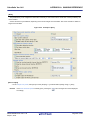
[Macro Setting] tab
This tab allows you to view the information (Macro Information) on and change the setting for the peripheral function
node "[System], [Port], etc." selected in the Project Tree panel, or the peripheral function button "
,
, etc."
pressed in the Code Generator panel.
Figure A-9. [Macro Setting] Tab
(1)
The following items are explained here.
- [How to open]
- [Description of each area]
[How to open]
- On the Project Tree panel, select [Project name (Project)] >> [Code Generator (Design Tool)] >> Peripheral function node "[System], [Port], etc.", and then select [Property] from the [View] menu.
- On the Project Tree panel, select [Project name (Project)] >> [Code Generator (Design Tool)] >> Peripheral function node "[System], [Port], etc.", and then select [Property] from the context menu.
Remarks 1.
If this panel is already open, selecting a different peripheral function node "[System], [Port], etc." in the
Project Tree panel changes the content displayed accordingly.
2.
If this panel is already open, pressing a different type of peripheral function button "
,
, etc." in
the Code Generator panel changes the content displayed accordingly.
[Description of each area]
(1) [Macro Information] category
This area allows you to view the information (Macro name) on and change the setting for the peripheral function
node "[System], [Port], etc." selected in the Project Tree panel, or the peripheral function button pressed in the
Code Generator panel.
Macro name
Displays the type of peripheral function node selected in the Project Tree panel or
the type of peripheral function button pressed in the Code Generator panel.
R20UT0006EJ0100 Rev.1.00
Sep 01, 2010
Page 61 of 300
CubeSuite Ver.1.40
APPENDIX A WINDOW REFERENCE
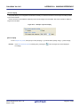
[File Setting] tab
This tab allows you to view the information (File Information) on and change the setting for the file selected in the Code
Generator Preview panel.
Figure A-10. [File Setting] Tab
(1)
The following items are explained here.
- [How to open]
- [Description of each area]
[How to open]
- On the Code Generator Preview panel, select a file, and then select [Property] from the [View] menu.
- On the Code Generator Preview panel, select a file, and then select [Property] from the context menu.
Remark
If this panel is already open, selecting a different file in the Code Generator Preview panel changes the content displayed accordingly.
[Description of each area]
(1) [File Information] category
This area allows you to view the information (Default, File name) on and change the setting for the file selected in
the Code Generator Preview panel.
Default name
Views or selects the setting that determines whether the name of the file selected in
the Code Generator Preview panel is a default name or not.
Yes
The file name is a default name.
Changing this area from "No" to "Yes" changes the
name of the file to its default name.
No
File name
The file name is not a default name.
Displays or change the name of the file selected on the Code Generator Preview
panel.
R20UT0006EJ0100 Rev.1.00
Sep 01, 2010
Page 62 of 300
CubeSuite Ver.1.40
APPENDIX A WINDOW REFERENCE
Device Pin List panel
This panel allows you to enter information on each pin of the microcontroller.
Figure A-11. Device Pin List Panel
(1)
(2)
(3)
The following items are explained here.
- [How to open]
- [Description of each area]
- [[File] menu (Device Pin List panel-dedicated items)]
- [[Help] menu (Device Pin List panel-dedicated items)]
[How to open]
- On the Project Tree panel, select [Project name (Project)] >> [Pin Configurator (Design Tool)] >> [Device Pin List].
- From the [View] menu, select [Pin Configurator] >> [Device Pin List].
[Description of each area]
(1) Toolbar
This area consists of the following buttons.
Displays the information in the Device pin list area in an expanded view.
Displays the information in the Device pin list area in a folded view only.
Clicks this button to automatically process the configuration information in the
selected function, I/O, N-ch, and other fields after selecting one of the peripheral
functions displayed in the first level on the [Macro] tab.
Clicks this button to initialize the selected function, I/O, N-ch, and other fields after
selecting one of the peripheral functions displayed in the first level on the [Macro]
tab.
Clicks this button to create an external peripheral controller from the external peripheral controller information on the [External Peripheral] tab, and display it in the
Device Top View panel.
Clicks this button to delete the information for the external peripheral controller displayed on the [External Peripheral] tab, on the first layer.
R20UT0006EJ0100 Rev.1.00
Sep 01, 2010
Page 63 of 300
CubeSuite Ver.1.40
Remarks 1.
Click the
APPENDIX A WINDOW REFERENCE
button to add the information in question as a choice in the "External Parts" column
of the [Macro] tab and the [Pin Number] tab.
2.
Click the
button to remove the external peripheral component in question from the Device top
view area if the Device Top View panel.
(2) Device pin list area
This area displays the "device pin list" for entering information on the pins of the microcontroller.
(3) Tab selection area
Selecting the tab changes the order in which "information on each pin of the microcontroller" is displayed.
This panel has the following tabs:
- [Pin Number] tab
This tab displays information on each pin of the microcontroller in the order of pin number.
- [Macro] tab
This tab displays information on each pin of the microcontroller in the order it was grouped into peripheral
functions.
- [External Peripheral] tab
This tab displays information about the pins connected to external peripherals in order grouped at the externalperipheral component level.
[[File] menu (Device Pin List panel-dedicated items)]
Save Pin List
Saves a report file (a file containing information configured using Pin Configurator: device
pin list) overwriting the existing file.
Save Pin List As...
Opens the Save As dialog box for naming and saving a report file (a file containing information configured using Pin Configurator: device pin list).
[[Help] menu (Device Pin List panel-dedicated items)]
Open Help for Device Pin List
Displays the help of this panel.
Panel
R20UT0006EJ0100 Rev.1.00
Sep 01, 2010
Page 64 of 300
CubeSuite Ver.1.40
APPENDIX A WINDOW REFERENCE
[Pin Number] tab
This tab displays information on each pin of the microcontroller in the order of pin number.
Figure A-12. [Pin Number] Tab
(1)
The following items are explained here.
- [How to open]
- [Description of each area]
[How to open]
- On the Project Tree panel, select [Project name (Project)] >> [Pin Configurator (Design Tool)] >> [Device Pin List].
- From the [View] menu, select [Pin Configurator] >> [Device Pin List].
[Description of each area]
(1) Device pin list area
This area displays the "device pin list" for entering information on the pins of the microcontroller.
The device pin list in this area is organized in the order of pin number.
The following are the columns comprising the device pin list.
Column Heading
Outline
Pin Number
Displays the pin number of the pin.
Pin Name
This area allows you to select "which function to use" when the pin has more than
one functions.
Function
This area allows you to select "which function to use" when the pin has more than
one functions.
I/O
This area allows you to select the I/O mode of the pin.
N-ch
This area allows you to select "which output mode to apply" when using the pin in
the output mode.
Define Name
This area allows you to assign a "user-defined pin name" to the pin.
Description
Displays the summary of function of the pin.
R20UT0006EJ0100 Rev.1.00
Sep 01, 2010
Page 65 of 300
CubeSuite Ver.1.40
APPENDIX A WINDOW REFERENCE
Column Heading
Outline
Recommend Connection For
Displays instructions on how to handle the pin when it is not used.
Unused
This column displays information only when the "Free" is selected in the "Function"
column.
Attention
Displays the precaution on using the pin.
External Parts
This area is for selecting which external peripheral controller to connect the pin to.
Remarks 1.
You cannot add information in the "Pin Number" column, "Pin Name" column, "Description" column, "Recommend Connection For Unused" column and "Attention" column because they contain
fixed information.
2.
If the "Free" in the "Function" column is changed to a specific pin name, color of the corresponding
pin in the Device Top View panel changes from the "color representing the unused pins" to the
"color representing the used pins" selected by clicking [Device Top View Settings] tab >> [Color] in
the Property panel.
3.
To move columns (change the display order) in the device pin list, drag and drop the desired
column to the desired location.
4.
To add the "user's own column", use the New Column dialog box which opens by pressing the
[New Column] button in the Column Chooser dialog box which opens by pressing the
button in
the upper left corner of the device pin list.
R20UT0006EJ0100 Rev.1.00
Sep 01, 2010
Page 66 of 300
CubeSuite Ver.1.40
APPENDIX A WINDOW REFERENCE
[Macro] tab
This tab displays information on each pin of the microcontroller in the order it was grouped into peripheral functions.
Figure A-13. [Macro] Tab
(1)
The following items are explained here.
- [How to open]
- [Description of each area]
[How to open]
- On the Project Tree panel, select [Project name (Project)] >> [Pin Configurator (Design Tool)] >> [Device Pin List].
- From the [View] menu, select [Pin Configurator] >> [Device Pin List].
[Description of each area]
(1) Device pin list area
This area displays the "device pin list" for entering information on the pins of the microcontroller.
The device pin list in this area is organized in the order the pins were grouped into peripheral functions.
(a) First layer
The following are the columns comprising the device pin list.
Column Heading
Outline
Macro Name
Displays the name of the peripheral function.
Total
Displays the total number of pins assigned to the peripheral function.
Used
Displays the total number of pins for which the purpose has been set.
Used in Other Macro
Displays the total number of pins for which the purpose has been set by other
peripheral functions.
R20UT0006EJ0100 Rev.1.00
Sep 01, 2010
Page 67 of 300
CubeSuite Ver.1.40
APPENDIX A WINDOW REFERENCE
(b) Second layer
Column Heading
Outline
Pin Number
Displays the pin number of the pin.
Pin Name
Displays the pin name of the pin.
Function
This area allows you to select "which function to use" when the pin has more
than one functions.
I/O
This area allows you to select the I/O mode of the pin.
N-ch
This area allows you to select "which output mode to apply" when using the pin
in the output mode.
Define Name
This area allows you to assign a "user-defined pin name" to the pin.
Description
Displays the summary of function of the pin.
Recommend Connection For
Displays instructions on how to handle the pin when it is not used.
Unused
This column displays information only when the "Free" is selected in the
"Function" column.
Attention
Displays the precaution on using the pin.
External Parts
This area is for selecting which external peripheral controller to connect the pin
to.
Remarks 1.
You cannot add information in the "Macro Name", "Total", "Used", "Used by other function", "Pin
Number", "Pin Name", "Description", "Recommend Connection For Unused" and "Attention" columns because they contain fixed information.
2.
If the "Free" in the "Function" column is changed to a specific pin name, color of the corresponding
pin in the Device Top View panel changes from the "color representing the unused pins" to the
"color representing the used pins" selected by clicking [Device Top View Settings] tab >> [Color] in
the Property panel.
3.
To move columns (change the display order) in the device pin list, drag and drop the desired column to the desired location.
4.
To add the "user's own column", use the New Column dialog box which opens by pressing the
[New Column] button in the Column Chooser dialog box which opens by pressing the
button in
the upper left corner of the device pin list.
R20UT0006EJ0100 Rev.1.00
Sep 01, 2010
Page 68 of 300
CubeSuite Ver.1.40
APPENDIX A WINDOW REFERENCE
[External Peripheral] tab
This tab displays information about the pins connected to external peripherals in order grouped at the external-peripheral component level.
Figure A-14. [External Peripheral] Tab
(1)
The following items are explained here.
- [How to open]
- [Description of each area]
[How to open]
- On the Project Tree panel, select [Project name (Project)] >> [Pin Configurator (Design Tool)] >> [Device Pin List].
- From the [View] menu, select [Pin Configurator] >> [Device Pin List].
[Description of each area]
(1) Device pin list area
This area displays the “device pin list“ for entering information on the pins connected to external peripheral parts.
Note that items in this area's device pin list are sorted by groups at the external peripheral controller level.
(a) First layer
The following are the columns comprising the device pin list.
Column Heading
External Peripheral
Outline
Displays the name of the external peripheral controller.
To change the name, select this field and then press the [F2] key.
Total
Displays the total number of pins allocated for connection with the microcontroller.
R20UT0006EJ0100 Rev.1.00
Sep 01, 2010
Page 69 of 300
CubeSuite Ver.1.40
APPENDIX A WINDOW REFERENCE
(b) Second layer
Column Heading
Outline
Pin Number
Displays the pin number of the pin.
Pin Name
Displays the pin name of the pin.
Function
This area allows you to select "which function to use" when the pin has more
than one functions.
I/O
This area allows you to select the I/O mode of the pin.
N-ch
This area allows you to select "which output mode to apply" when using the pin
in the output mode.
Define Name
This area allows you to assign a "user-defined pin name" to the pin.
Description
Displays the summary of function of the pin.
Recommend Connection For
Displays instructions on how to handle the pin when it is not used.
Unused
This column displays information only when the "Free" is selected in the "Function" column.
Attention
Remarks 1.
Displays the precaution on using the pin.
You cannot add information in the "External Peripheral Name", "Connected Pins", "Pin Number",
"Pin Name”, "Description", "Recommend Connection For Unused" and "Attention" columns
because they contain fixed information.
2.
If the "Free" in the "Function" column is changed to a specific pin name, color of the corresponding
pin in the Device Top View panel changes from the "color representing the unused pins" to the
"color representing the used pins" selected by clicking [Device Top View Settings] tab >> [Color] in
the Property panel.
3.
To move columns (change the display order) in the device pin list, drag and drop the desired column to the desired location.
4.
To add the "user's own column", use the New Column dialog box which opens by pressing the
[New Column] button in the Column Chooser dialog box which opens by pressing the
button in
the upper left corner of the device pin list.
R20UT0006EJ0100 Rev.1.00
Sep 01, 2010
Page 70 of 300
CubeSuite Ver.1.40
APPENDIX A WINDOW REFERENCE
Device Top View panel
This panel displays the information entered in the Device Pin List panel.
Figure A-15. Device Top View Panel
(1)
(2)
(3)
The following items are explained here.
- [How to open]
- [Description of each area]
- [[File] menu (Device Top View panel-dedicated items)]
- [[Help] menu (Device Top View panel-dedicated items)]
- [Context menu]
[How to open]
- On the Project Tree panel, select [Project name (Project)] >> [Pin Configurator (Design Tool)] >> [Device Top
View].
- From the [View] menu, select [Pin Configurator] >> [Device Top View].
Remark
In the Property panel, on the [Pin Configurator Settings] tab, if "BGA" is selected for the Package type, then
this panel cannot be opened.
R20UT0006EJ0100 Rev.1.00
Sep 01, 2010
Page 71 of 300
CubeSuite Ver.1.40
APPENDIX A WINDOW REFERENCE
[Description of each area]
(1) Toolbar
This area consists of the following buttons.
Clicks this button to enable changing of the display in the Device top view area by
drag and drop.
By pressing this button, the shape of the mouse cursor in the Device top view area
changes from the arrow to the hand.
Clicks this button to enable moving external peripheral components in the Device
top view area to arbitrary locations, and select pins.
By pressing this button, the shape of the mouse cursor which has changed into the
hand by pressing the
button reverts back to the arrow.
Rotates the content in the Device top view area 90 degrees counter-clockwise.
Rotates the content in the Device top view area 90 degrees clockwise.
Expands or reduces the content in the Device top view area.
(2) [User Define] area
Drag and drop the
button from this area to the Device top view area to creat and display an external peripheral
controller.
(3) Device top view area
This area displays the pin assignment of the microcontroller.
Settings of the pin assignment are displayed using the colors specified by selecting [Device Top View Settings] tab
>> [Color] in the Property panel.
Remark
If the pin name in the diagram is double-clicked, the Device Pin List panel opens and the focus moves
to the clicked pin in the list.
[[File] menu (Device Top View panel-dedicated items)]
Save Top View
Saves a report file (a file containing information configured using Pin Configurator: device
top view) overwriting the existing file.
Save Top View As...
Opens the Save As dialog box for naming and saving a report file (a file containing information configured using Pin Configurator: device top view).
[[Help] menu (Device Top View panel-dedicated items)]
Open Help for Device Top View
Displays the help of this panel.
Panel
[Context menu]
When you right click on a pin or external peripheral controller in the Device top view area, the following context menu
displays.
R20UT0006EJ0100 Rev.1.00
Sep 01, 2010
Page 72 of 300
CubeSuite Ver.1.40
APPENDIX A WINDOW REFERENCE
(1) When a pin is right clicked
Use as
If the pin has multiple functions, select which function to use.
Connect to External Peripheral
Selects which external peripheral controller to connect the pin to.
(2) When an external peripheral controller is right clocked
Disconnect Pin
Disconnects from the pin.
Delete External Peripheral
Removes the external peripheral controller.
R20UT0006EJ0100 Rev.1.00
Sep 01, 2010
Page 73 of 300
CubeSuite Ver.1.40
APPENDIX A WINDOW REFERENCE
Code Generator panel
This panel allows you to configure the information necessary to control the peripheral functions provided by the microcontroller.
Figure A-16. Code Generator Panel: [System]
(1)
(2)
The following items are explained here.
- [How to open]
- [Description of each area]
- [[File] menu (Code Generator panel-dedicated items)]
- [[Help] menu (Code Generator panel-dedicated items)]
[How to open]
- On the Project Tree panel, select [Project name (Project)] >> [Code Generator (Design Tool)] >> Peripheral function node "[System], [Port], etc.".
Remark
If this panel is already open, pressing a different peripheral function button "
,
, etc." changes the
content displayed in the Information setting area accordingly.
R20UT0006EJ0100 Rev.1.00
Sep 01, 2010
Page 74 of 300
CubeSuite Ver.1.40
APPENDIX A WINDOW REFERENCE
[Description of each area]
(1) Toolbar
This area consists of the following "peripheral function buttons".
When there is peripheral function target microcontroller is not supporting, peripheral functionbutton is not
disokayed.
Reflects settings made on this panel in the Device Pin List panel. This button will be
grayed out (disabled) if "Not reflected" is selected in the [PinPart Combination Mode]
category of the [Generation] tab.
Outputs the source code (device driver program) to the folder specified by selecting
[Generation] tab >> [Output folder] in the Property panel.
Changes the content displayed in the Information setting area to the "[System] for
configuring the information necessary to control the functions of clock generator, onchip debug function and etc. provided by the microcontroller".
Changes the content displayed in the Information setting area to the "[Port] for configuring the information necessary to control the port functions provided by the
microcontroller".
Changes the content displayed in the Information setting area to the "[INT] for configuring the information necessary to control the interrupt functions and the key interrupt function provided by the microcontroller".
Changes the content displayed in the Information setting area to the "[Serial] for
configuring the information necessary to control the functions of serial array unit and
functions of serial interface provided by the microcontroller".
Changes the content displayed in the Information setting area to the "[Operational
Amplifier] for configuring the information necessary to control the functions of comparator/programmable gain amplifier provided by the microcontroller".
Changes the content displayed in the Information setting area to the "[Comparator]
for configuring the information necessary to control the function of comparator provided by the microcontroller".
Changes the content displayed in the Information setting area to the "[A/D] for configuring the information necessary to control the function of A/D converter provided
by the microcontroller".
Changes the content displayed in the Information setting area to the "[Timer] for
configuring the information necessary to control the functions of timer array unit provided by the microcontroller".
Changes the content displayed in the Information setting area to the "[Watchdog
Timer] for configuring the information necessary to control the functions of watchdog
timer provided by the microcontroller".
Changes the content displayed in the Information setting area to the "[RTC] for configuring the information necessary to control the functions of real-time counter provided by the microcontroller".
Changes the content displayed in the Information setting area to the "[Clock Output]
for configuring the information necessary to control the functions of clock output controller provided by the microcontroller".
Changes the content displayed in the Information setting area to the "[LVI] for configuring the information necessary to control the functions of low-voltage detector provided by the microcontroller".
R20UT0006EJ0100 Rev.1.00
Sep 01, 2010
Page 75 of 300
CubeSuite Ver.1.40
APPENDIX A WINDOW REFERENCE
(2) Information setting area
The content displayed in this area differs depending on the "peripheral function node" or "peripheral function button" selected or pressed when opening this panel.
See the following sections for details on this area.
- [System]
- [Port]
- [INT]
- [Serial]
- [Operational Amplifier]
- [Comparator]
- [A/D]
- [Timer]
- [Watchdog Timer]
- [RTC]
- [Clock Output]
- [LVI]
Remark
See User's Manual for Microcontroller for details on the items to be set.
[[File] menu (Code Generator panel-dedicated items)]
Save Code Generator Report
Outputs report files (a file containing information configured using Code Generator and a
file containing information regarding the source code).
Remarks 1.
The output format for the report file (either HTML or CSV) is selected by clicking [Generation] tab >>
[Report type] in the Property panel.
2.
The destination folder for the report file is specified by clicking [Generation] tab >> [Output folder] in the
Property panel.
[[Help] menu (Code Generator panel-dedicated items)]
Open Help for Code Generator
Displays the help of this panel.
Panel
R20UT0006EJ0100 Rev.1.00
Sep 01, 2010
Page 76 of 300
CubeSuite Ver.1.40
APPENDIX A WINDOW REFERENCE
[System]
This panel allows you to configure the information necessary to control the functions of clock generator, on-chip debug
function and etc. provided by the microcontroller.
Screen Structure may be different, depending on the kinds of target microcontrollers. See user's manual for details on
target microcontrollers.
Figure A-17. Example of [System]
[How to open]
- On the Project Tree panel, select [Project name (Project)] >> [Code Generator (Design Tool)] >> [System].
Remark
If the Code Generator panel is already open, pressing the
button changes the content displayed
accordingly.
R20UT0006EJ0100 Rev.1.00
Sep 01, 2010
Page 77 of 300
CubeSuite Ver.1.40
APPENDIX A WINDOW REFERENCE
[Port]
This panel allows you to configure the information necessary to control port functions provided by the microcontroller.
Screen Structure may be different, depending on the kinds of target microcontrollers. See user's manual for details on
target microcontrollers.
Figure A-18. Example of [Port]
[How to open]
- On the Project Tree panel, select [Project name (Project)] >> [Code Generator (Design Tool)] >> [Port].
Remark
If the Code Generator panel is already open, pressing the
button changes the content displayed
accordingly.
R20UT0006EJ0100 Rev.1.00
Sep 01, 2010
Page 78 of 300
CubeSuite Ver.1.40
APPENDIX A WINDOW REFERENCE
[INT]
This panel allows you to configure the information necessary to control the interrupt functions and the key interrupt
function provided by the microcontroller.
Screen Structure may be different, depending on the kinds of target microcontrollers. See user's manual for details on
target microcontrollers.
Figure A-19. Example of [INT]
[How to open]
- On the Project Tree panel, select [Project name (Project)] >> [Code Generator (Design Tool)] >> [INT].
Remark
If the Code Generator panel is already open, pressing the
button changes the content displayed
accordingly.
R20UT0006EJ0100 Rev.1.00
Sep 01, 2010
Page 79 of 300
CubeSuite Ver.1.40
APPENDIX A WINDOW REFERENCE
[Serial]
This panel allows you to configure the information necessary to control the functions of serial array unit and functions of
serial interface provided by the microcontroller.
Screen Structure may be different, depending on the kinds of target microcontrollers. See user's manual for details on
target microcontrollers.
Figure A-20. Example of [Serial]
[How to open]
- On the Project Tree panel, select [Project name (Project)] >> [Code Generator (Design Tool)] >> [Serial].
Remark
If the Code Generator panel is already open, pressing the
button changes the content displayed
accordingly.
R20UT0006EJ0100 Rev.1.00
Sep 01, 2010
Page 80 of 300
CubeSuite Ver.1.40
APPENDIX A WINDOW REFERENCE
[Operational Amplifier]
This panel allows you to configure the information necessary to control the functions of operational amplifier provided
by the microcontroller.
Screen Structure may be different, depending on the kinds of target microcontrollers. See user's manual for details on
target microcontrollers.
Figure A-21. Example of [Operational Amplifier]
[How to open]
- On the Project Tree panel, select [Project name (Project)] >> [Code Generator (Design Tool)] >> [Operational
Amplifier].
Remark
If the Code Generator panel is already open, pressing the
button changes the content displayed
accordingly.
R20UT0006EJ0100 Rev.1.00
Sep 01, 2010
Page 81 of 300
CubeSuite Ver.1.40
APPENDIX A WINDOW REFERENCE
[Comparator]
This panel allows you to configure the information necessary to control the functions of comparator provided by the
microcontroller.
Screen Structure may be different, depending on the kinds of target microcontrollers. See user's manual for details on
target microcontrollers.
Figure A-22. Example of [Comparator]
[How to open]
- On the Project Tree panel, select [Project name (Project)] >> [Code Generator (Design Tool)] >> [Comparator].
Remark
If the Code Generator panel is already open, pressing the
button changes the content displayed
accordingly.
R20UT0006EJ0100 Rev.1.00
Sep 01, 2010
Page 82 of 300
CubeSuite Ver.1.40
APPENDIX A WINDOW REFERENCE
[A/D]
This panel allows you to configure the information necessary to control the function of A/D converter provided by the
microcontroller.
Screen Structure may be different, depending on the kinds of target microcontrollers. See user's manual for details on
target microcontrollers.
Figure A-23. Example of [A/D]
[How to open]
- On the Project Tree panel, select [Project name (Project)] >> [Code Generator (Design Tool)] >> [A/D].
Remark
If the Code Generator panel is already open, pressing the
button changes the content displayed
accordingly.
R20UT0006EJ0100 Rev.1.00
Sep 01, 2010
Page 83 of 300
CubeSuite Ver.1.40
APPENDIX A WINDOW REFERENCE
[Timer]
This panel allows you to configure the information necessary to control the function of timer array unit provided by the
microcontroller.
Screen Structure may be different, depending on the kinds of target microcontrollers. See user's manual for details on
target microcontrollers.
Figure A-24. Example of [Timer]
[How to open]
- On the Project Tree panel, select [Project name (Project)] >> [Code Generator (Design Tool)] >> [Timer].
Remark
If the Code Generator panel is already open, pressing the
button changes the content displayed
accordingly.
R20UT0006EJ0100 Rev.1.00
Sep 01, 2010
Page 84 of 300
CubeSuite Ver.1.40
APPENDIX A WINDOW REFERENCE
[Watchdog Timer]
This panel allows you to configure the information necessary to control the function of watchdog timer provided by the
microcontroller.
Screen Structure may be different, depending on the kinds of target microcontrollers. See user's manual for details on
target microcontrollers.
Figure A-25. Example of [Watchdog Timer]
[How to open]
- On the Project Tree panel, select [Project name (Project)] >> [Code Generator (Design Tool)] >> [Watchdog
Timer].
Remark
If the Code Generator panel is already open, pressing the
button changes the content displayed
accordingly.
R20UT0006EJ0100 Rev.1.00
Sep 01, 2010
Page 85 of 300
CubeSuite Ver.1.40
APPENDIX A WINDOW REFERENCE
[RTC]
This panel allows you to configure the information necessary to control the function of real-time counter provided by the
microcontroller.
Screen Structure may be different, depending on the kinds of target microcontrollers. See user's manual for details on
target microcontrollers.
Figure A-26. Example of [RTC]
[How to open]
- On the Project Tree panel, select [Project name (Project)] >> [Code Generator (Design Tool)] >> [RTC].
Remark
If the Code Generator panel is already open, pressing the
button changes the content displayed
accordingly.
R20UT0006EJ0100 Rev.1.00
Sep 01, 2010
Page 86 of 300
CubeSuite Ver.1.40
APPENDIX A WINDOW REFERENCE
[Clock Output]
This panel allows you to configure the information necessary to control the functions of clock output controller provided
by the microcontroller.
Screen Structure may be different, depending on the kinds of target microcontrollers. See user's manual for details on
target microcontrollers.
Figure A-27. Example of [Clock Output]
[How to open]
- On the Project Tree panel, select [Project name (Project)] >> [Code Generator (Design Tool)] >> [Clock Output].
Remark
If the Code Generator panel is already open, pressing the
button changes the content displayed
accordingly.
R20UT0006EJ0100 Rev.1.00
Sep 01, 2010
Page 87 of 300
CubeSuite Ver.1.40
APPENDIX A WINDOW REFERENCE
[LVI]
This panel allows you to configure the information necessary to control the functions of low-voltage detector provided
by the microcontroller.
Screen Structure may be different, depending on the kinds of target microcontrollers. See user's manual for details on
target microcontrollers.
Figure A-28. Example of [LVI]
[How to open]
- On the Project Tree panel, select [Project name (Project)] >> [Code Generator (Design Tool)] >> [LVI].
Remark
If the Code Generator panel is already open, pressing the
button changes the content displayed
accordingly.
R20UT0006EJ0100 Rev.1.00
Sep 01, 2010
Page 88 of 300
CubeSuite Ver.1.40
APPENDIX A WINDOW REFERENCE
Code Generator Preview panel
This panel allows you to confirm or configure on a per-API function basis the setting that determines whether or not the
source code (device driver program) is generated when the
button is pressed in the Code Genera-
tor panel. It also allows you to confirm the source code that reflects the information configured in the Code Generator
panel.
Figure A-29. Code Generator Preview Panel
(1)
(2)
The following items are explained here.
- [How to open]
- [Description of each area]
- [File] menu (Code Generator Preview panel-dedicated items)]
- [[Help] menu (Code Generator Preview panel-dedicated items)]
- [Context menu]
[How to open]
- From the [View] menu, select [Code Generator Preview].
[Description of each area]
(1) Preview tree
This area allows you to confirm or configure on a per-API function basis the setting that determines whether or not
the source code (device driver program) is generated when the
button is pressed in the Code
Generator panel.
R20UT0006EJ0100 Rev.1.00
Sep 01, 2010
Page 89 of 300
CubeSuite Ver.1.40
Remarks 1.
APPENDIX A WINDOW REFERENCE
You can change the source code to be displayed by selecting the source file name or API function
name in this tree.
2.
To select whether or not to generate the source code, use the context menu (Generate code/Not
generate code) which is displayed by right-clicking the mouse while the mouse cursor is on the
desired icon in the tree.
3.
You can confirm the current setting that determines whether or not to generate the source code by
checking the type of icon.
Table A-2. Setting That Determines Whether or Not to Generate the Source Code
Type of Icon
Outline
Source code for the currently selected API function is generated.
If this icon is displayed next to the API function, the corresponding source code must be generated (it is impossible to
change the icon to
).
Source code for the currently selected API function is generated.
Source code for the currently selected API function is not
generated.
(2) Source code display area
This area allows you to confirm the source code (device driver program) that reflects the information configured in
the Code Generator panel.
The following table displays the meaning of the color of the source code text displayed in this area.
Table A-3. Color of Source Code
Color
Outline
Green
Comment
Blue
Reserved word for C compiler
Red
Numeric value
Black
Code section
Gray
File name
Remarks 1.
2.
You cannot edit the source code within this panel.
For some of the API functions (such as API functions for serial array units), values such as the
SFR register value are calculated and finalized when the source code is generated (when the
button on the Code Generator panel is pressed). For this reason, the source
code displayed in this panel may not be the same as that would actually be generated.
3.
You can change the source code to be displayed by selecting the source file name or API function
name in the preview tree.
[File] menu (Code Generator Preview panel-dedicated items)]
Save Code Generator Report
Outputs report files (a file containing information configured using Code Generator and a
file containing information regarding the source code).
R20UT0006EJ0100 Rev.1.00
Sep 01, 2010
Page 90 of 300
CubeSuite Ver.1.40
Remarks 1.
APPENDIX A WINDOW REFERENCE
The output format for the report file (either HTML or CSV) is selected by clicking [Generation] tab >>
[Report type] in the Property panel.
2.
The destination folder for the report file is specified by clicking [Generation] tab >> [Output folder] in the
Property panel.
[[Help] menu (Code Generator Preview panel-dedicated items)]
Open Help for Code Generator
Displays the help of this panel.
Preview Panel
[Context menu]
The following context menu items are displayed by right clicking the mouse.
Generate code
Makes a setting so that the source code of the currently selected API function is generated to the folder specified by selecting [Generation] tab >> [Output folder] in the Property panel.
Selecting this context menu item changes the icon of the currently selected API function
from
Not generate code
to
.
Makes a setting so that the source code of the currently selected API function is not generated when the
button is pressed in the Code Generator panel.
Selecting this context menu item changes the icon of the currently selected API function
from
Rename
to
.
Selecting this menu item changes the name portion of the currently selected file or API
function into an edit box for editing the name.
You can change the name of the file or API function by editing its name in the edit box.
Default
Reverts the file name or API function name to its original name before it was edited.
Property
Opens the Property panel that contains the information for the currently selected file.
R20UT0006EJ0100 Rev.1.00
Sep 01, 2010
Page 91 of 300
CubeSuite Ver.1.40
APPENDIX A WINDOW REFERENCE
Output panel
This panel displays operation logs for various components (design tool, build tool, etc.) provided by CubeSuite.
Figure A-30. Output Panel
(1)
(2)
The following items are explained here.
- [How to open]
- [Description of each area]
- [[File] menu (Output panel-dedicated items)]
- [[Edit] menu (Output panel-dedicated items)]
- [[Help] menu (Output panel-dedicated items)]
- [Context menu]
[How to open]
- From the [View] menu, select [Output].
[Description of each area]
(1) Message area
This area displays operation logs for various components (design tool, build tool, etc.) provided by CubeSuite.
The following table displays the meaning of the color of the message text displayed in this area.
Table A-4. Color of Message Text/Background
Message Text/Background
Block/White
Description
Information message
Displayed with information notices.
Blue/Standard color
Warning message
Displayed with warnings about operations.
Red/LightGray
Fatal error message
Displayed when there is a fatal error, or when execution is not possible due to a
operational mistake.
Remark
See the sections "[All Output Messages] tab" and "[Code Generator] tab" for details on the content displayed in this area.
(2) Tab selection area
Select the source of message.
Remark
When the new message is output, "*" mark is displayed to the left of the tab name.
R20UT0006EJ0100 Rev.1.00
Sep 01, 2010
Page 92 of 300
CubeSuite Ver.1.40
APPENDIX A WINDOW REFERENCE
[[File] menu (Output panel-dedicated items)]
Save Output-Tab Name
Saves the message corresponding to the specified tab overwriting the existing file.
Save Output-Tab Name As...
Opens the Save As dialog box for naming and saving the message corresponding to the
specified tab.
[[Edit] menu (Output panel-dedicated items)]
Copy
Sends the character string or lines selected with range selection to the clipboard.
Select All
Selects all the messages displayed on the Message area.
Search...
Opens the Search and Replace dialog box for searching strings with the [Quick Search]
tab selected.
Replace...
Opens the Search and Replace dialog box for replacing strings with the [Whole Replace]
tab selected.
[[Help] menu (Output panel-dedicated items)]
Open Help for Output Panel
Displays the help of this panel.
[Context menu]
The following context menu items are displayed by right clicking the mouse.
Copy
Sends the character string or lines selected with range selection to the clipboard.
Select All
Selects all the messages displayed on the Message area.
Clear
Deletes all the messages displayed on the Message area.
Stop Searching
Cancels the search currently being executed.
This is invalid when a search is not being executed.
Open Help for Message
Displays help for the message on the current caret location.
This only applies to warning messages and error messages.
R20UT0006EJ0100 Rev.1.00
Sep 01, 2010
Page 93 of 300
CubeSuite Ver.1.40
APPENDIX A WINDOW REFERENCE
[All Output Messages] tab
This tab displays operation logs for all components (design tool, build tool, etc.) provided by CubeSuite.
Figure A-31. [All Output Messages] Tab
(1)
The following items are explained here.
- [How to open]
- [Description of each area]
[How to open]
- From the [View] menu, select [Output].
[Description of each area]
(1) Message area
This area displays operation logs for all components (design tool, build tool, etc.) provided by CubeSuite.
The following table displays the meaning of the color of the message text displayed in this area.
Table A-5. Color of Message Text/Background
Message Text/Background
Black/White
Description
Information message
Displayed with information notices.
Blue/Standard Color
Warning message
Displayed with warnings about operations.
Red/LightGray
Fatal error message
Displayed when there is a fatal error, or when execution is not possible due to a
operational mistake.
R20UT0006EJ0100 Rev.1.00
Sep 01, 2010
Page 94 of 300
CubeSuite Ver.1.40
APPENDIX A WINDOW REFERENCE
[Code Generator] tab
This tab displays only operation logs for Code Generator out of those for various components (design tool, build tool,
etc.) provided by CubeSuite.
Figure A-32. [Code Generator] Tab
(1)
The following items are explained here.
- [How to open]
- [Description of each area]
[How to open]
- From the [View] menu, select [Output].
[Description of each area]
(1) Message area
This area displays only operation logs for Code Generator out of those for various components (design tool, build
tool, etc.) provided by CubeSuite.
The following table displays the meaning of the color of the message text displayed in this area.
Table A-6. Color of Message Text/Background
Message Text/Background
Black/White
Outline
Information message
Displayed with information notices.
Blue/Standard Color
Warning message
Displayed with warnings about operations.
Red/LightGray
Fatal error message
Displayed when there is a fatal error, or when execution is not possible due to a
operational mistake.
R20UT0006EJ0100 Rev.1.00
Sep 01, 2010
Page 95 of 300
CubeSuite Ver.1.40
APPENDIX A WINDOW REFERENCE
Column Chooser dialog box
This dialog box allows you to choose whether or not to display the item listed in this dialog box in the device pin list, and
add columns to or delete columns from the device pin list.
Figure A-33. Column Chooser Dialog Box
(1)
(2)
[Function buttons]
The following items are explained here.
- [How to open]
- [Description of each area]
- [Function buttons]
[How to open]
- In the [Pin Number] tab of the Device Pin List panel, click the
- In the [Macro] tab of the Device Pin List panel, click the
button.
button.
- In the [External Peripheral] tab of the Device Pin List panel, click the
button.
[Description of each area]
(1) Operational object selection area
This area allows you to select the device pin list to be configured in this dialog box.
Pin Number
Configures the device pin list corresponding to the [Pin Number] tab.
Macro
Configures the device pin list belonging to the first layer of the [Macro] tab.
Macro - Pin
Configures the device pin list belonging to the second layer of the [Macro] tab.
External Peripheral
Configures the device pin list belonging to the first layer of the [External Peripheral]
tab.
External Peripheral - Pin
Configures the device pin list belonging to the second layer of the [External Peripheral] tab.
R20UT0006EJ0100 Rev.1.00
Sep 01, 2010
Page 96 of 300
CubeSuite Ver.1.40
APPENDIX A WINDOW REFERENCE
Figure A-34. Operational Object ([Pin Number] Tab)
Figure A-35. Operational Object ([Macro] Tab: First Layer)
Figure A-36. Operational Object ([Macro] Tab: Second Layer)
R20UT0006EJ0100 Rev.1.00
Sep 01, 2010
Page 97 of 300
CubeSuite Ver.1.40
APPENDIX A WINDOW REFERENCE
Figure A-37. Operational Object ([External Peripheral] Tab: First Layer)
Figure A-38. Operational Object ([External Peripheral] Tab: Second Layer)
(2) Displayed item selection area
Select whether or not to display the item selected in the Operational object selection area in the device pin list.
Checked
Displays the selected item in the device pin list.
Not checked
Hides the selected item in the device pin list.
[Function buttons]
Button
Function
New Column
Opens the New Column dialog box for adding columns to the device pin list.
Delete Column
Deletes the selected columns from the device pin list.
You can only delete the column which you added using the New Column dialog box.
Default
Restores the column order to the default settings.
Close
Closes this dialog box.
R20UT0006EJ0100 Rev.1.00
Sep 01, 2010
Page 98 of 300
CubeSuite Ver.1.40
APPENDIX A WINDOW REFERENCE
New Column dialog box
This dialog box allows you to add your own column to the device pin list.
Figure A-39. New Column Dialog Box
(1)
(2)
[Function buttons]
The following items are explained here.
- [How to open]
- [Description of each area]
- [Function buttons]
[How to open]
- Click the [New Column] button in the Column Chooser dialog box.
[Description of each area]
(1) [Name]
This area allows you to enter column headings of the columns added to the device pin list.
(2) [Type]
Select the input format of the column to add to the device pin list.
Text
Only character strings can be entered in the column.
Cehck box
Adds a column of check boxes.
Whole number
Only integers can be entered in the column.
Real number
Only real numbers can be entered in the column.
Date
Only dates in YYYYMMDD format can be entered in the column.
[Function buttons]
Button
OK
Function
Adds a column that has the column heading specified in the [Name] to the right end of
the device pin list.
Cancel
R20UT0006EJ0100 Rev.1.00
Sep 01, 2010
Ignores the setting and closes this dialog box.
Page 99 of 300
CubeSuite Ver.1.40
APPENDIX A WINDOW REFERENCE
Browse For Folder dialog box
This dialog box allows you to specify the output destination for files (source code, report file, etc.).
Figure A-40. Browse For Folder Dialog Box
(1)
[Function buttons]
The following items are explained here.
- [How to open]
- [Description of each area]
- [Function buttons]
[How to open]
- In the [Generation] tab of the Property panel, click the [...] button in [Output folder].
[Description of each area]
(1) Folder location
Select the folder to which the files (source code, report file, etc.) are output.
[Function buttons]
Button
Function
Make New Folder
Creates a "New Folder" below the folder selected in the Folder location.
OK
Specifies the folder selected in the Folder location as the destination for the files.
Cancel
Ignores the setting and closes this dialog box.
R20UT0006EJ0100 Rev.1.00
Sep 01, 2010
Page 100 of 300
CubeSuite Ver.1.40
APPENDIX A WINDOW REFERENCE
Save As dialog box
This dialog box allows you to name and save a file (such as a report file).
Figure A-41. Save As Dialog Box
(1)
(2)
(3)
(4)
[Function buttons]
The following items are explained here.
- [How to open]
- [Description of each area]
- [Function buttons]
[How to open]
- From the [File] menu, select [Save <object> As...].
[Description of each area]
(1) [Save in]
Select the folder to which the files (report files, etc.) are output.
(2) List of files
This area displays a list of files matching the conditions selected in [Save in] and [Save as type].
R20UT0006EJ0100 Rev.1.00
Sep 01, 2010
Page 101 of 300
CubeSuite Ver.1.40
APPENDIX A WINDOW REFERENCE
(3) [File name]
Specify the name of the file to be output.
(4) [Save as type]
Select the type of the file to be output.
Microsoft Office Excel Book (*.xls)
Microsoft Office Excel Book format
Bitmap (*.bmp)
Bitmap format
PNG (*.png)
PNG format
JPEG (*.jpg)
JPEG format
EMF (*.emf)
EMF format
[Function buttons]
Button
Save
Function
Outputs a file having the name specified in the [File name] and [Save as type] to the
folder specified in the [Save in].
Cancel
R20UT0006EJ0100 Rev.1.00
Sep 01, 2010
Ignores the setting and closes this dialog box.
Page 102 of 300
CubeSuite Ver.1.40
APPENDIX B OUTPUT FILES
APPENDIX B OUTPUT FILES
This appendix describes the files output by Code Generator.
B.1
Overview
Below is a list of files output by Code Generator.
Table B-1. File List
Unit of Output
Peripheral function
Project
File Name
Description
CG_PeripheralFunctionName.c
Initial function, API function
CG_PeripheralFunctionName_user.c
Interrupt function, callback function
CG_PeripheralFunctionName.h
Defines macros for assigning values to registers
CG_option.asm
Option bytes, secures ROM for MINICUBE2
CG_systeminit.c
Call initial function of peripheral function
Call CG_ReadResetSource
B.2
CG_main.c
main function
CG_macrodriver.h
Defines common macros used by all source files
CG_user_define.h
Empty file (for user definitions)
CG_lk.dir
Link directive
Output File
Below are the files (peripheral function) output by Code Generator.
Table B-2. File List (PeripheralFunction)
Peripheral Function
System
Source File Name
CG_system.c
Names of API Functions Included
CLOCK_Init
CG_ChangeClockMode
CG_ChangeFrequency
CG_SelectPowerSaveMode
CG_SelectStabTime
CG_ChangePllMode
CG_system_user.c
CLOCK_UserInit
CG_ReadResetSource
Port
CG_system.h
-
CG_port.c
PORT_Init
PORT_ChangePmnInput
PORT_ChangePmnOutput
INT
CG_port_user.c
PORT_UserInit
CG_port.h
-
CG_int.c
INTP_Init
KEY_Init
INT_MaskableInterruptEnable
INTPn_Disable
R20UT0006EJ0100 Rev.1.00
Sep 01, 2010
Page 103 of 300
CubeSuite Ver.1.40
APPENDIX B OUTPUT FILES
Peripheral Function
INT
Source File Name
CG_int.c
Names of API Functions Included
INTPn_Enable
KEY_Disable
KEY_Enable
CG_int_user.c
MD_INTPn
MD_INTKR
INTP_UserInit
KEY_UserInit
Serial
CG_int.h
-
CG_serial.c
UART6_Init
UART6_Start
UART6_Stop
UART6_SendData
UART6_ReceiveData
CSI1n_Init
CSI1n_Start
CSI1n_Stop
CSI1n_ReceiveData
CSI1n_SendReceiveData
IICA_Init
IICA_Stop
IICA_MasterSendStart
IICA_MasterReceiveStart
IICA_StopCondition
IICA_SlaveSendStart
IICA_SlaveReceiveStart
CG_serial_user.c
MD_INTSR6
MD_INTSRE6
MD_INTST6
MD_INTCSI1n
MD_INTIICA0
UART6_UserInit
UART6_SendEndCallback
UART6_ReceiveEndCallback
UART6_SoftOverRunCallback
UART6_ErrorCallback
CSI1n_UserInit
CSI1n_SendEndCallback
CSI1n_ReceiveEndCallback
IICA_UserInit
IICA_MasterSendEndCallback
IICA_MasterReceiveEndCallback
IICA_MasterErrorCallback
IICA_SlaveSendEndCallback
IICA_SlaveReceiveEndCallback
IICA_SlaveErrorCallback
IICA_GetStopConditionCallback
R20UT0006EJ0100 Rev.1.00
Sep 01, 2010
Page 104 of 300
CubeSuite Ver.1.40
APPENDIX B OUTPUT FILES
Peripheral Function
Source File Name
Names of API Functions Included
Serial
CG_serial.h
-
Operational Amplifier
CG_opamp.c
OPAMP_Init
PGA_Start
PGA_Stop
PGA_ChangePGAFactor
AMP_Start
AMP_Stop
AMPn_Start
AMPn_Stop
Comparator
CG_opamp_user.c
OPAMP_UserInit
CG_opamp.h
-
CG_comparator.c
Comparator_Init
Comparatorn_Start
Comparatorn_Stop
CG_comparator_user.c
MD_INTCMPn
Comparator_UserInit
A/D
CG_comparator.h
-
CG_ad.c
AD_Init
AD_ComparatorOn
AD_ComparatorOff
AD_Start
AD_Stop
AD_SelectADChannel
AD_Read
AD_ReadByte
CG_ad_user.c
MD_INTAD
AD_UserInit
Timer
CG_ad.h
-
CG_timer.c
TMX_Init
TMXn_Start
TMXn_Stop
TMXn_ChangeDuty
TMXn_ChangeDualDuty
TMX_EnableHighImpedanceState
TMX_DisableHighImpedanceState
TM00_Init
TM00_Start
TM00_Stop
TM00_ChangeTimerCondition
TM00_GetFreeRunningValue
TM00_SoftwareTriggerOn
TM00_ChangeDuty
TM00_GetPulseWidth
TM5n_Init
TM5n_Start
R20UT0006EJ0100 Rev.1.00
Sep 01, 2010
Page 105 of 300
CubeSuite Ver.1.40
APPENDIX B OUTPUT FILES
Peripheral Function
Timer
Source File Name
CG_timer.c
Names of API Functions Included
TM5n_Stop
TM5n_ChangeTimerCondition
TM5n_ChangeDuty
TMHn_Init
TMHn_Start
TMHn_Stop
TMHn_ChangeTimerCondition
TMHn_ChangeDuty
TMH1_CarrierOutputEnable
TMH1_CarrierOutputDisable
CG_timer_user.c
MD_INTTMXn
MD_INTTM0n0
MD_INTTM5n
MD_INTMHn
TM00_UserInit
TM5n_UserInit
TMHn_UserInit
Watchdog Timer
RTC
CG_timer.h
-
CG_wdt.c
WDT_Restart
CG_wdt.h
-
CG_rtc.c
RTC_Init
RTC_PowerOff
RTC_CounterEnable
RTC_CounterDisable
RTC_SetHourSystem
RTC_CounterSet
RTC_CounterGet
RTC_ConstPeriodInterruptEnable
RTC_ConstPeriodInterruptDisable
RTC_AlarmEnable
RTC_AlarmDisable
RTC_AlarmSet
RTC_AlarmGet
RTC_IntervalStart
RTC_IntervalStop
RTC_IntervalInterruptEnable
RTC_IntervalInterruptDisable
RTC_RTC1HZ_OutputEnable
RTC_RTC1HZ_OutputDisable
RTC_RTCCL_OutputEnable
RTC_RTCCL_OutputDisable
RTC_RTCDIV_OutputEnable
RTC_RTCDIV_OutputDisable
RTC_ChangeCorrectionValue
CG_rtc_user.c
MD_INTRTC
MD_INTRTCl
R20UT0006EJ0100 Rev.1.00
Sep 01, 2010
Page 106 of 300
CubeSuite Ver.1.40
APPENDIX B OUTPUT FILES
Peripheral Function
RTC
Source File Name
CG_rtc_user.c
Names of API Functions Included
RTC_UserInit
RTC_ConstPeriodInterruptCallback
RTC_AlarmInterruptCallback
Clock Output
CG_rtc.h
-
CG_pcl.c
PCL_Init
PCL_Start
PCL_Stop
PCL_ChangeFreq
LVI
CG_pcl_user.c
PCL_UserInit
CG_pcl.h
-
CG_lvi.c
LVI_Init
LVI_InterruptModeStart
LVI_ResetModeStart
LVI_Stop
LVI_SetLVILevel
CG_lvi_user.c
MD_INTLVI
LVI_UserInit
CG_lvi.h
R20UT0006EJ0100 Rev.1.00
Sep 01, 2010
-
Page 107 of 300
CubeSuite Ver.1.40
APPENDIX C API FUNCTIONS
APPENDIX C API FUNCTIONS
This appendix describes the API functions output by Code Generator.
C.1
Overview
Below are the naming conventions for API functions output by Code Generator.
- Macro names are in ALL CAPS.
- The number in front of the macro name is a hexadecimal value; this is the same value as the macro value.
- Local variable names are in all lower case.
- Global variable names start with a "g" and use Camel Case.
- Names of pointers to local variables start with a "p" and are in all lower case.
- Names of pointers to global variables start with a "gp" and use Camel Case.
- Names of elements in enum statements are in ALL CAPS.
C.2
Output Function
Below is a list of API functions output by Code Generator.
Table C-1. API Function List
Peripheral Function
System
API Function Name
CLOCK_Init
Function
Performs initialization required to control the clock generator, on-chip debug, and etc. .
CLOCK_UserInit
Performs user-defined initialization relating to the clock
generator, on-chip debug, and etc. .
CG_ReadResetSource
Performs processing in response to RESET signal.
CG_ChangeClockMode
Changes the CPU clock/peripheral hardware clock.
CG_ChangeFrequency
Changes the division ratio of the CPU clock/peripheral
hardware clock.
CG_SelectPowerSaveMode
Configures the CPU's standby function.
CG_SelectStabTime
Configures the oscillation stabilization time of the X1
clock.
Port
CG_ChangePllMode
Controls the operation of PLL function.
PORT_Init
Performs initialization necessary to control port functions.
PORT_UserInit
Performs user-defined initialization relating to the port.
PORT_ChangePmnInput
Switches the pin's I/O mode from output mode to input
mode.
PORT_ChangePmnOutput
Switches the pin's I/O mode from input mode to output
mode.
INT
INTP_Init
Performs initialization necessary to control the external
interrupt INTPn functions.
INTP_UserInit
Performs user-defined initialization relating to the external interrupt INTPn functions.
KEY_Init
Performs initialization necessary to control the key
interrupt INTKR functions.
R20UT0006EJ0100 Rev.1.00
Sep 01, 2010
Page 108 of 300
CubeSuite Ver.1.40
APPENDIX C API FUNCTIONS
Peripheral Function
INT
API Function Name
KEY_UserInit
Function
Performs user-defined initialization relating to the key
interrupt INTKR functions.
INT_MaskableInterruptEnable
Disables/enables the acceptance of the maskable interrupts.
INTPn_Disable
Disables the acceptance of the maskable interrupts
INTPn (external interrupt requests).
INTPn_Enable
Enables the acceptance of the maskable interrupts
INTPn (external interrupt requests).
Serial
KEY_Disable
Disables the acceptance of the key interrupts INTKR.
KEY_Enable
Enables the acceptance of the key interrupts INTKR.
UART6_Init
Performs initialization of the serial interface (UART6)
channel.
UART6_UserInit
Performs user-defined initialization of the serial interface (UART6).
UART6_Start
Sets UART communication to standby mode.
UART6_Stop
Ends UART communication.
UART6_SendData
Starts UART data transmission.
UART6_ReceiveData
Starts UART data reception.
UART6_SendEndCallback
Performs processing in response to the UART transmission complete interrupt INTST6.
UART6_ReceiveEndCallback
Performs processing in response to the UART reception complete interrupt INTSR6.
UART6_SoftOverRunCallback
Performs processing in response to the UART reception complete interrupt INTSR6.
UART6_ErrorCallback
Performs processing in response to the UART communication error interrupt INTSRE6.
CSI1n_Init
Performs initialization of the serial interface (CSI1n)
channel.
CSI1n_UserInit
Performs user-defined initialization of the serial interface (CSI1n).
CSI1n_Start
Sets CSI1n communication to standby mode.
CSI1n_Stop
Ends CSI1n communication.
CSI1n_ReceiveData
Starts CSI1n data reception.
CSI1n_SendReceiveData
Starts CSI1n data transmission/reception.
CSI1n_SendEndCallback
Performs processing in response to the CSI1n
communication complete interrupt INTCSI1n.
CSI1n_ReceiveEndCallback
Performs processing in response to the CSI1n
communication complete interrupt INTCSI1n.
IICA_Init
Performs initialization of the serial interface (IICA).
IICA_UserInit
Performs user-defined initialization of the serial interface (IICA).
IICA_Stop
R20UT0006EJ0100 Rev.1.00
Sep 01, 2010
Ends IICA communication.
Page 109 of 300
CubeSuite Ver.1.40
APPENDIX C API FUNCTIONS
Peripheral Function
Serial
API Function Name
Function
IICA_MasterSendStart
Starts IICA master transmission.
IICA_MasterReceiveStart
Starts IICA master reception.
IICA_StopCondition
Generates stop conditions.
IICA_MasterSendEndCallback
Performs processing in response to the IICA
communication complete interrupt INTIICA0.
IICA_MasterReceiveEndCallback
Performs processing in response to the IICA
communication complete interrupt INTIICA0.
IICA_MasterErrorCallback
Performs processing in response to detection of error in
IICA master communication.
IICA_SlaveSendStart
Starts IICA slave transmission.
IICA_SlaveReceiveStart
Starts IICA slave reception.
IICA_SlaveSendEndCallback
Performs processing in response to the IICA
communication complete interrupt INTIICA0.
IICA_SlaveReceiveEndCallback
Performs processing in response to the IICA
communication complete interrupt INTIICA0.
IICA_SlaveErrorCallback
Performs processing in response to detection of error in
IICA slave communication.
IICA_GetStopConditionCallback
Performs processing in response to detection of stop
condition in IICA slave communication.
Operational Amplifier
OPAMP_Init
Performs initialization necessary to control operational
amplifier functions.
OPAMP_UserInit
Performs user-defined initialization relating to the
operational amplifier.
PGA_Start
Starts the operation of operational amplifier (PGA
mode).
PGA_Stop
Ends the operation of operational amplifier (PGA
mode).
PGA_ChangePGAFactor
Sets the input voltage amplification factor of a
operational amplifier (PGA mode).
AMP_Start
Starts the operation of operational amplifier (single AMP
mode).
AMP_Stop
Ends the operation of operational amplifier (single AMP
mode).
AMPn_Start
Starts the operation of operational amplifier n (single
AMP mode).
AMPn_Stop
Ends the operation of operational amplifier n (single
AMP mode).
Comparator
Comparator_Init
Performs initialization necessary to control comparator
functions.
Comparator_UserInit
Performs user-defined initialization relating to the comparator.
Comparatorn_Start
Starts the operation of comparator n.
Comparatorn_Stop
Ends the operation of comparator n.
R20UT0006EJ0100 Rev.1.00
Sep 01, 2010
Page 110 of 300
CubeSuite Ver.1.40
APPENDIX C API FUNCTIONS
Peripheral Function
A/D
API Function Name
AD_Init
Function
Performs initialization necessary to control A/D converter functions.
AD_UserInit
Performs user-defined initialization relating to the A/D
converter.
AD_ComparatorOn
Enables operation of voltage converter.
AD_ComparatorOff
Disables operation of voltage converter.
AD_Start
Starts A/D conversion.
AD_Stop
Ends A/D conversion.
AD_SelectADChannel
Configures the analog voltage input pin for A/D conversion.
AD_Read
Reads the results of A/D conversion (10 bits).
AD_ReadByte
Reads the results of A/D conversion (8 bits; most significant 8 bits of 10-bit resolution).
Timer
TMX_Init
Performs initialization necessary to control 16-bit timer
Xn functions.
TMXn_Start
Starts the count for 16-bit timer Xn.
TMXn_Stop
Ends the count for 16-bit timer Xn.
TMXn_ChangeDuty
Changes the duty ratio of the PWM signal single-output
to the TOX0n pin.
TMXn_ChangeDualDuty
Changes the duty ratio of the PWM signal dulal-output
to the TOX0n pin.
TMX_EnableHighImpedanceState
Begins high impedance output of the 16-bit timer Xn.
TMX_DisableHighImpedanceState
Ends high impedance output of the 16-bit timer Xn.
TM00_Init
Performs initialization necessary to control 16-bit timer/
event counter 00 functions.
TM00_UserInit
Performs user-defined initialization relating to the 16-bit
timer/event counter 00.
TM00_Start
Starts the count for 16-bit timer/event counter 00.
TM00_Stop
Ends the count for 16-bit timer/event counter 00.
TM00_ChangeTimerCondition
Changes the value of capture/compare control register
00 (CRC00).
TM00_GetFreeRunningValue
Captures the content of the capture register (CR0n0).
TM00_SoftwareTriggerOn
Generates the trigger (software trigger) for one-shot
pulse output.
TM00_ChangeDuty
Changes the duty ratio of the signal output to the TO00
pin.
TM00_GetPulseWidth
Captures the high/low-level width measured for the signal (pulses) input to the TI0n0 pin.
TM5n_Init
Performs initialization necessary to control 8-bit timer/
event counter 5n functions.
TM5n_UserInit
Performs user-defined initialization relating to the 8-bit
timer/event counter 5n.
R20UT0006EJ0100 Rev.1.00
Sep 01, 2010
Page 111 of 300
CubeSuite Ver.1.40
APPENDIX C API FUNCTIONS
Peripheral Function
Timer
API Function Name
Function
TM5n_Start
Starts the count for 8-bit timer/event counter 5n.
TM5n_Stop
Ends the count for 8-bit timer/event counter 5n.
TM5n_ChangeTimerCondition
Changes the value of 8-bit timer compare register 5n
(CR5n).
TM5n_ChangeDuty
Changes the duty ratio of the PWM signal output to the
TO5n pin.
TMHn_Init
Performs initialization necessary to control 8-bit timer
Hn functions.
TMHn_UserInit
Performs user-defined initialization relating to the 8-bit
timer Hn.
TMHn_Start
Starts the count for 8-bit timer Hn.
TMHn_Stop
Ends the count for 8-bit timer Hn.
TMHn_ChangeTimerCondition
Changes the value of 8-bit timer H compare register 0n/
1n (CMP0n/CMP1n).
TMHn_ChangeDuty
Changes the duty ratio of the PWM signal output to the
TOHn pin.
TMH1_CarrierOutputEnable
Begins carrier pulse output of the 8-bit timer H1 (carrier
generator mode).
TMH1_CarrierOutputDisable
Ends carrier pulse output of the 8-bit timer H1 (carrier
generator mode).
Watchdog Timer
WDT_Restart
Clears the watchdog timer counter and resumes counting.
RTC
RTC_Init
Performs initialization necessary to control real-time
counter functions.
RTC_UserInit
Performs user-defined initialization relating to the realtime counter.
RTC_PowerOff
Halts the clock supplied to the real-time counter.
RTC_CounterEnable
Starts the count of the real-time counter (year, month,
weekday, day, hour, minute, second).
RTC_CounterDisable
Ends the count of the real-time counter (year, month,
weekday, day, hour, minute, second).
RTC_SetHourSystem
Sets the clock type (12-hour or 24-hour clock) of the
real-time counter.
RTC_CounterSet
Sets the counter value (year, month, weekday, day,
hour, minute, second) of the real-time counter.
RTC_CounterGet
Reads the counter value (year, month, weekday, day,
hour, minute, second) of the real-time counter.
RTC_ConstPeriodInterruptEnable
Sets the cycle of the interrupts INTRTC, then starts the
cyclic interrupt function.
RTC_ConstPeriodInterruptDisable
Ends the cyclic interrupt function.
RTC_ConstPeriodInterruptCallback
Performs processing in response to the cyclic interrupt
INTRTC.
RTC_AlarmEnable
R20UT0006EJ0100 Rev.1.00
Sep 01, 2010
Starts the alarm interrupt function.
Page 112 of 300
CubeSuite Ver.1.40
APPENDIX C API FUNCTIONS
Peripheral Function
RTC
API Function Name
Function
RTC_AlarmDisable
Ends the alarm interrupt function.
RTC_AlarmSet
Sets the alarm conditions (weekday, hour, minute).
RTC_AlarmGet
Reads the alarm conditions (weekday, hour, minute).
RTC_AlarmInterruptCallback
Performs processing in response to the alarm interrupt
INTRTC.
RTC_IntervalStart
Starts the interval interrupt function.
RTC_IntervalStop
Ends the interval interrupt function.
RTC_IntervalInterruptEnable
Sets the cycle of the interrupts, then starts the interval
interrupt INTRTCI function.
RTC_IntervalInterruptDisable
Ends the interval interrupt function.
RTC_RTC1HZ_OutputEnable
Enables output of the real-time counter correction clock
(1 Hz) to the RTC1HZ pin.
RTC_RTC1HZ_OutputDisable
Disables output of the real-time counter correction clock
(1 Hz) to the RTC1HZ pin.
RTC_RTCCL_OutputEnable
Enables output of the real-time counter clock (32 kHz
source) to the RTCCL pin.
RTC_RTCCL_OutputDisable
Disables output of the real-time counter clock (32 kHz
source) to the RTCCL pin.
RTC_RTCDIV_OutputEnable
Enables output of the real-time counter clock (32 kHz
cycle) to the RTCDIV pin.
RTC_RTCDIV_OutputDisable
Disables output of the real-time counter clock (32 kHz
cycle) to the RTCDIV pin.
RTC_ChangeCorrectionValue
Changes the timing and correction value for correcting
clock errors.
Clock Output
PCL_Init
Performs initialization necessary to control clock output
control circuit functions.
PCL_UserInit
Performs user-defined initialization relating to the clock
output control circuits.
LVI
PCL_Start
Starts clock output.
PCL_Stop
Ends clock output.
PCL_ChangeFreq
Changes the output clock to the PCL pin.
LVI_Init
Performs initialization necessary to control low-voltage
detector functions.
LVI_UserInit
Performs user-defined initialization relating to the lowvoltage detector.
LVI_InterruptModeStart
Starts low-voltage detection (when in interrupt generation mode).
LVI_ResetModeStart
Starts low-voltage detection (when in internal reset
mode).
LVI_Stop
Stops low-voltage detection.
LVI_SetLVILevel
Sets the low-voltage detection level.
R20UT0006EJ0100 Rev.1.00
Sep 01, 2010
Page 113 of 300
CubeSuite Ver.1.40
C.3
APPENDIX C API FUNCTIONS
Function Reference
This section describes the API functions output by Code Generator, using the following notation format.
Figure C-1. Notation Format of API Functions
(1)
.........
(2)
.......................................................................................................................................
...........................
[Classification]
(3)
...........................
[Syntax]
(4)
...
.........
[Argument(s)]
(5)
I/O
...
Argument
...
.........
Description
.....................................................................
...........................
[Return value]
(6)
Macro
.........
Description
..................................................................................................................
...........................
[Example]
(7)
...........................
...........................
(1) Name
Indicates the name of the API function.
(2) Outline
Outlines the functions of the API function.
(3) [Classification]
Indicates the name of the C source file to which the API function is output.
(4) [Syntax]
Indicates the format to be used when describing an API function to be called in C language.
R20UT0006EJ0100 Rev.1.00
Sep 01, 2010
Page 114 of 300
CubeSuite Ver.1.40
APPENDIX C API FUNCTIONS
(5) [Argument(s)]
API function arguments are explained in the following format.
I/O
Argument
Description
(a)
(b)
(c)
(a) I/O
Argument classification
I
...
Input argument
O
...
Output argument
(b) Argument
Argument data type
(c) Description
Description of argument
(6) [Return value]
API function return value is explained in the following format.
Macro
Description
(a)
(b)
(a) Macro
Macro of return value
(b) Description
Description of return value
(7) [Example]
Shows an example of the API function in use.
R20UT0006EJ0100 Rev.1.00
Sep 01, 2010
Page 115 of 300
CubeSuite Ver.1.40
C.3.1
APPENDIX C API FUNCTIONS
System
Below is a list of API functions output by Code Generator for system use.
Table C-2. API Functions: [System]
API Function Name
Function
CLOCK_Init
Performs initialization required to control the clock generator, on-chip debug, and etc. .
CLOCK_UserInit
Performs user-defined initialization relating to the clock generator, on-chip debug, and
etc. .
CG_ReadResetSource
Performs processing in response to RESET signal.
CG_ChangeClockMode
Changes the CPU clock/peripheral hardware clock.
CG_ChangeFrequency
Changes the division ratio of the CPU clock/peripheral hardware clock.
CG_SelectPowerSaveMode
Configures the CPU's standby function.
CG_SelectStabTime
Configures the oscillation stabilization time of the X1 clock.
CG_ChangePllMode
Controls the operation of PLL function.
R20UT0006EJ0100 Rev.1.00
Sep 01, 2010
Page 116 of 300
CubeSuite Ver.1.40
APPENDIX C API FUNCTIONS
CLOCK_Init
Performs initialization required to control the clock generator, on-chip debug and etc. .
[Classification]
CG_system.c
[Syntax]
void
CLOCK_Init ( void );
[Argument(s)]
None.
[Return value]
None.
R20UT0006EJ0100 Rev.1.00
Sep 01, 2010
Page 117 of 300
CubeSuite Ver.1.40
APPENDIX C API FUNCTIONS
CLOCK_UserInit
Performs user-defined initialization relating to the clock generator, on-chip debug, and etc. .
Remark
This API function is called as the CLOCK_Init callback routine.
[Classification]
CG_system_user.c
[Syntax]
void
CLOCK_UserInit ( void );
[Argument(s)]
None.
[Return value]
None.
R20UT0006EJ0100 Rev.1.00
Sep 01, 2010
Page 118 of 300
CubeSuite Ver.1.40
APPENDIX C API FUNCTIONS
CG_ReadResetSource
Performs processing in response to RESET signal.
[Classification]
CG_system_user.c
[Syntax]
void
CG_ReadResetSource ( void );
[Argument(s)]
None.
[Return value]
None.
[Example]
Below are examples of the different processes executing depending on the RESET signal trigger.
[CG_Systeminit.c]
void systeminit ( void ) {
CG_ReadResetSource ();
/* Processes executed by RESET signal trigger */
......
}
[CG_system_user.c]
#include
"CG_macrodriver.h"
void CG_ReadResetSource ( void ) {
UCHAR
flag = RESF;
if ( flag & 0x1 ) {
......
/* Reset control flag register: Obtain RESF contents */
/* Trigger identification: Check LVIRF flag */
/* Internal reset request by low-voltage detector */
} else if ( flag & 0x10 ) { /* Trigger identification: Check WDTRF flag */
......
/* Internal reset request by watchdog timer */
}
......
}
R20UT0006EJ0100 Rev.1.00
Sep 01, 2010
Page 119 of 300
CubeSuite Ver.1.40
APPENDIX C API FUNCTIONS
CG_ChangeClockMode
Changes the CPU clock/peripheral hardware clock.
[Classification]
CG_system.c
[Syntax]
#include
"CG_macrodriver.h"
#include
"CG_system.h"
MD_STATUS
CG_ChangeClockMode ( enum ClockMode mode );
[Argument(s)]
I/O
I
Argument
enum
ClockMode mode;
Description
CPU clock (fCPU)/peripheral hardware clock (fPRS) type
HIOCLK:
fCPU/fPRS >> Internal high-speed oscillation clock
HIOSYSCLK:
fCPU >> Internal high-speed oscillation clock, fPRS
>> High-spped system clock
SYSX1CLK:
fCPU/fPRS >> X1 clock
SYSEXTCLK: fCPU/fPRS >> External main system clock
SUBXT1CLK: fCPU >> XT1 clock
SUBEXTCLK: fCPU >> External subsystem clock
Remark
SUBXT1CLK and SUBEXTCLK can only be specified when the target device is a 78K0/KC2-L.
[Return value]
Macro
Description
MD_OK
Normal completion
MD_ERROR1
Exit with error (abend)
- Cannot change fCPU/fPRS to the internal high-speed osillation clock.
MD_ERROR2
Exit with error (abend)
- Cannot change fCPU to the internal high-speed oscillation clock.
- Cannot change fPRS to the high-speed system clock.
MD_ERROR3
Exit with error (abend)
- Cannot change fCPU/fPRS to the X1 clock.
MD_ERROR4
Exit with error (abend)
- Cannot change fCPU/fPRS to the external main system clock.
MD_ERROR5
Exit with error (abend) [Kx2-L]
- Cannot change fCPU to the XT1 clock.
MD_ERROR6
Exit with error (abend) [Kx2-L]
- Cannot change fCPU to the external subsystem clock.
MD_ARGERROR
Invalid argument specification
R20UT0006EJ0100 Rev.1.00
Sep 01, 2010
Page 120 of 300
CubeSuite Ver.1.40
Remark
APPENDIX C API FUNCTIONS
The values MD_ERROR5 and MD_ERROR6 will only be returned when the target device is a 78K0/KC2-L.
R20UT0006EJ0100 Rev.1.00
Sep 01, 2010
Page 121 of 300
CubeSuite Ver.1.40
APPENDIX C API FUNCTIONS
CG_ChangeFrequency
Changes the division ratio of the CPU clock/peripheral hardware clock.
[Classification]
CG_system.c
[Syntax]
#include
"CG_macrodriver.h"
#include
"CG_system.h"
MD_STATUS
CG_ChangeFrequency ( enum CPUClock clock );
[Argument(s)]
I/O
I
Argument
enum
CPUClock
clock;
Description
Division ratio type
SYSTEMCLOCK:
fMAIN
SYSONEHALF:
fMAIN/2
SYSONEFOURTH:
fMAIN/4
SYSONEEIGHTH:
fMAIN/8
SYSONESIXTEENTH: fMAIN/16
Remark
"fMAIN" signifies the frequency of the main system clock.
[Return value]
Macro
Description
MD_OK
Normal completion
MD_ARGERROR
Invalid argument specification
R20UT0006EJ0100 Rev.1.00
Sep 01, 2010
Page 122 of 300
CubeSuite Ver.1.40
APPENDIX C API FUNCTIONS
CG_SelectPowerSaveMode
Configures the CPU's standby function.
[Classification]
CG_system.c
[Syntax]
#include
"CG_macrodriver.h"
#include
"CG_system.h"
MD_STATUS
CG_SelectPowerSaveMode ( enum PSLevel level );
[Argument(s)]
I/O
Argument
I
enum
PSLevel level;
Description
Standby function type
PSSTOP: STOP mode
PSHALT:
HALT mode
[Return value]
Macro
Description
MD_OK
Normal completion
MD_ERROR
Exit with error (abend) [Kx2-L]
- If the CPU is operating by XT1 clock, then STOP mode cannot be specified.
MD_ARGERROR
Remark
Invalid argument specification
The value MD_ERROR will only be returned when the target device is a 78K0/KC2-L.
[Example]
Below is an example of changing the standby function to "STOP mode".
[CG_main.c]
#include
"CG_macrodriver.h"
#include
"CG_system.h"
void main ( void ) {
MD_STATUS
ret;
......
TM00_Stop ();
/* Stop count */
ret = CG_SelectPowerSaveMode ( PSSTOP );
/* Change to STOP mode */
if ( ret != MD_OK ) {
while ( 1 );
}
R20UT0006EJ0100 Rev.1.00
Sep 01, 2010
Page 123 of 300
CubeSuite Ver.1.40
APPENDIX C API FUNCTIONS
TM00_Init ();
/* Initialize TM00 */
TM00_Start ();
/* Start count */
......
}
R20UT0006EJ0100 Rev.1.00
Sep 01, 2010
Page 124 of 300
CubeSuite Ver.1.40
APPENDIX C API FUNCTIONS
CG_SelectStabTime
Configures the oscillation stabilization time of the X1 clock.
[Classification]
CG_system.c
[Syntax]
#include
"CG_macrodriver.h"
#include
"CG_system.h"
MD_STATUS
CG_SelectStabTime ( enum StabTime waittime );
[Argument(s)]
I/O
I
Argument
enum
StabTime
waittime;
Description
Oscillation stabilization time type
STLEVEL0: 2^11/fx
STLEVEL1: 2^13/fx
STLEVEL2: 2^14/fx
STLEVEL3: 2^15/fx
STLEVEL4: 2^16/fx
Remark
"fx" signifies the frequency of the X1 clock.
[Return value]
Macro
Description
MD_OK
Normal completion
MD_ARGERROR
Invalid argument specification
R20UT0006EJ0100 Rev.1.00
Sep 01, 2010
Page 125 of 300
CubeSuite Ver.1.40
APPENDIX C API FUNCTIONS
CG_ChangePllMode
Controls the operation of PLL function.
[Classification]
CG_system.c
[Syntax]
#include
"CG_macrodriver.h"
#include
"CG_system.h"
MD_STATUS
CG_ChangePllMode ( enum PllMode pllmode );
[Argument(s)]
I/O
I
Argument
enum
PllMode pllmode;
Description
Control of operation
SYSPLLON:
Enable operation
SYSPLLOFF: Stop operation
[Return value]
Macro
Description
MD_OK
Normal completion
MD_ARGERROR
Invalid argument specification
R20UT0006EJ0100 Rev.1.00
Sep 01, 2010
Page 126 of 300
CubeSuite Ver.1.40
C.3.2
APPENDIX C API FUNCTIONS
Port
Below is a list of API functions output by Code Generator for port use.
Table C-3. API Functions: [Port]
API Function Name
Function
PORT_Init
Performs initialization necessary to control port functions.
PORT_UserInit
Performs user-defined initialization relating to the port.
PORT_ChangePmnInput
Switches the pin's I/O mode from output mode to input mode.
PORT_ChangePmnOutput
Switches the pin's I/O mode from input mode to output mode.
R20UT0006EJ0100 Rev.1.00
Sep 01, 2010
Page 127 of 300
CubeSuite Ver.1.40
APPENDIX C API FUNCTIONS
PORT_Init
Performs initialization necessary to control port functions.
[Classification]
CG_port.c
[Syntax]
void
PORT_Init ( void );
[Argument(s)]
None.
[Return value]
None.
R20UT0006EJ0100 Rev.1.00
Sep 01, 2010
Page 128 of 300
CubeSuite Ver.1.40
APPENDIX C API FUNCTIONS
PORT_UserInit
Performs user-defined initialization relating to the port.
Remark
This API function is called as the PORT_Init callback routine.
[Classification]
CG_port_user.c
[Syntax]
void
PORT_UserInit ( void );
[Argument(s)]
None.
[Return value]
None.
R20UT0006EJ0100 Rev.1.00
Sep 01, 2010
Page 129 of 300
CubeSuite Ver.1.40
APPENDIX C API FUNCTIONS
PORT_ChangePmnInput
Switches the pin's I/O mode from output mode to input mode.
[Classification]
CG_port.c
[Syntax]
The format for specifying this API function differs according to whether the target pin has built-in pull-up resistance/a
SMBus input buffer.
- Built-in pull-up resistance: none; SMBus input buffer: none
void
PORT_ChangePmnInput ( void );
- Built-in pull-up resistance: yes; SUBus input buffer: none
#include
void
"CG_macrodriver.h"
PORT_ChangePmnInput ( BOOL enablepu );
- Built-in pull-up resistance: yes; SMBus input buffer: yes
#include
void
Remark
"CG_macrodriver.h"
PORT_ChangePmnInput ( BOOL enablepu, BOOL enablesmbus );
mn is the port number.
[Argument(s)]
I/O
I
Argument
BOOL
I
BOOL
Description
Built-in pull-up resistance used
enablepu;
MD_TRUE:
Yes
MD_FALSE:
No
Input buffer type
enablesmbus;
MD_TRUE:
SMBus input buffer
MD_FALSE:
Normal input buffer
[Return value]
None.
[Example 1]
Below is shown an example where pin P00 (built-in pull-up resistance: yes; SMBus input buffer: none) is changed as
follows:
I/O mode type:
Input mode
Built-in pull-up resistance used:
Yes
R20UT0006EJ0100 Rev.1.00
Sep 01, 2010
Page 130 of 300
CubeSuite Ver.1.40
APPENDIX C API FUNCTIONS
[CG_main.c]
#include
"CG_macrodriver.h"
void main ( void ) {
......
PORT_ChangeP00Input ( MD_TRUE );
/* Switch I/O mode */
......
}
[Example 2]
Below is shown an example where pin P00 (built-in pull-up resistance: yes; SMBus input buffer: none) is changed as
follows:
I/O mode type:
Input mode
Built-in pull-up resistance used:
No
[CG_main.c]
#include
"CG_macrodriver.h"
void main ( void ) {
......
PORT_ChangeP00Input ( MD_FALSE );
/* Switch I/O mode */
......
}
[Example 3]
Below is shown an example where pin P04 (built-in pull-up resistance: yes; SMBus input buffer: yes) is changed as follows:
I/O mode type:
Input mode
Built-in pull-up resistance used:
No
Input buffer type:
SMBus input buffer
[CG_main.c]
#include
"CG_macrodriver.h"
void main ( void ) {
......
PORT_ChangeP04Input ( MD_FALSE, MD_TRUE );
/* Switch I/O mode */
......
}
R20UT0006EJ0100 Rev.1.00
Sep 01, 2010
Page 131 of 300
CubeSuite Ver.1.40
APPENDIX C API FUNCTIONS
PORT_ChangePmnOutput
Switches the pin's I/O mode from input mode to output mode.
[Classification]
CG_port.c
[Syntax]
The format for specifying this API function differs according to whether the target pin conducts N-ch open drain output.
- N-ch open drain output: none
#include
void
"CG_macrodriver.h"
PORT_ChangePmnOutput ( BOOL initialvalue );
- N-ch open drain output: yes
#include
void
Remark
"CG_macrodriver.h"
PORT_ChangePmnOutput ( BOOL enablench, BOOL initialvalue );
nm is the port number.
[Argument(s)]
I/O
I
Argument
BOOL
enablench;
Description
Output mode type
MD_TRUE: N-ch open drain output (VDD withstand voltage) mode
MD_FALSE: Normal output mode
I
BOOL
initialvalue;
Initial output value
MD_SET:
Output HIGH level "1"
MD_CLEAR: Output LOW level "0"
[Return value]
None.
[Example 1]
Below is shown an example where pin P00 (N-ch open drain output: none) is changed as follows:
I/O mode type:
Output mode
Initial output value: Output HIGH level "1"
[CG_main.c]
#include
"CG_macrodriver.h"
void main ( void ) {
......
PORT_ChangeP00Output ( MD_SET );
R20UT0006EJ0100 Rev.1.00
Sep 01, 2010
/* Switch I/O mode */
Page 132 of 300
CubeSuite Ver.1.40
APPENDIX C API FUNCTIONS
......
}
[Example 2]
Below is shown an example where pin P04 (N-ch open drain output: yes) is changed as follows:
I/O mode type:
Output mode
Output mode type: N-ch open drain output (VDD withstand voltage) mode
Initial output value: Output LOW level "0"
[CG_main.c]
#include
"CG_macrodriver.h"
void main ( void ) {
......
PORT_ChangeP04Output ( MD_TRUE, MD_CLEAR ); /* Switch I/O mode */
......
}
R20UT0006EJ0100 Rev.1.00
Sep 01, 2010
Page 133 of 300
CubeSuite Ver.1.40
C.3.3
APPENDIX C API FUNCTIONS
INT
Below is a list of API functions output by Code Generator for interrupt and key interrupt use.
Table C-4. API Functions: [INT]
API Function Name
Function
INTP_Init
Performs initialization necessary to control the external interrupt INTPn functions.
INTP_UserInit
Performs user-defined initialization relating to the external interrupt INTPn functions.
KEY_Init
Performs initialization necessary to control the key interrupt INTKR functions.
KEY_UserInit
Performs user-defined initialization relating to the key interrupt INTKR functions.
INT_MaskableInterruptEnable
Disables/enables the acceptance of the maskable interrupts.
INTPn_Disable
Disables the acceptance of the maskable interrupts INTPn (external interrupt
requests).
INTPn_Enable
Enables the acceptance of the maskable interrupts INTPn (external interrupt
requests).
KEY_Disable
Disables the acceptance of the key interrupts INTKR.
KEY_Enable
Enables the acceptance of the key interrupts INTKR.
R20UT0006EJ0100 Rev.1.00
Sep 01, 2010
Page 134 of 300
CubeSuite Ver.1.40
APPENDIX C API FUNCTIONS
INTP_Init
Performs initialization necessary to control the external interrupt INTPn functions.
[Classification]
CG_int.c
[Syntax]
void
INTP_Init ( void );
[Argument(s)]
None.
[Return value]
None.
R20UT0006EJ0100 Rev.1.00
Sep 01, 2010
Page 135 of 300
CubeSuite Ver.1.40
APPENDIX C API FUNCTIONS
INTP_UserInit
Performs user-defined initialization relating to the external interrupt INTPn functions.
Remark
This API function is called as the INTP_Init callback routine.
[Classification]
CG_int_user.c
[Syntax]
void
INTP_UserInit ( void );
[Argument(s)]
None.
[Return value]
None.
R20UT0006EJ0100 Rev.1.00
Sep 01, 2010
Page 136 of 300
CubeSuite Ver.1.40
APPENDIX C API FUNCTIONS
KEY_Init
Performs initialization necessary to control the key interrupt INTKR functions.
[Classification]
CG_int.c
[Syntax]
void
KEY_Init ( void );
[Argument(s)]
None.
[Return value]
None.
R20UT0006EJ0100 Rev.1.00
Sep 01, 2010
Page 137 of 300
CubeSuite Ver.1.40
APPENDIX C API FUNCTIONS
KEY_UserInit
Performs user-defined initialization relating to the key interrupt INTKR functions.
Remark
This API function is called as the KEY_Init callback routine.
[Classification]
CG_int_user.c
[Syntax]
void
KEY_UserInit ( void );
[Argument(s)]
None.
[Return value]
None.
R20UT0006EJ0100 Rev.1.00
Sep 01, 2010
Page 138 of 300
CubeSuite Ver.1.40
APPENDIX C API FUNCTIONS
INT_MaskableInterruptEnable
Disables/enables the acceptance of the maskable interrupts.
[Classification]
CG_int.c
[Syntax]
#include
"CG_macrodriver.h"
#include
"CG_int.h"
MD_STATUS
INT_MaskableInterruptEnable ( enum MaskableSource name, BOOL enableflag );
[Argument(s)]
I/O
I
Argument
enum
MaskableSource
Description
name;
Maskable interrupt type
INT_xxx:
I
BOOL
enableflag;
Maskable interrupt
Acceptance enabled/disabled
MD_TRUE: Acceptance enabled
MD_FALSE: Acceptance disabled
Remark
See the header file CG_int.h for details about the maskable interrupt type INT_xxx.
[Return value]
Macro
Description
MD_OK
Normal completion
MD_ARGERROR
Invalid argument specification
[Example 1]
Below is an example of disabling acceptance of the maskable interrupt INTP0.
[CG_main.c]
#include
"CG_macrodriver.h"
#include
"CG_int.h"
void main ( void ) {
......
INT_MaskableInterruptEnable ( INT_INTP0, MD_FALSE );
interrupt INTP0 */
/* Disable acceptance of maskable
......
}
R20UT0006EJ0100 Rev.1.00
Sep 01, 2010
Page 139 of 300
CubeSuite Ver.1.40
APPENDIX C API FUNCTIONS
[Example 2]
Below is an example of enabling acceptance of the maskable interrupt INTP0.
[CG_main.c]
#include
"CG_macrodriver.h"
#include
"CG_int.h"
void main ( void ) {
......
INT_MaskableInterruptEnable ( INT_INTP0, MD_TRUE );
interrupt INTP0 */
/* Enable acceptance of maskable
......
}
R20UT0006EJ0100 Rev.1.00
Sep 01, 2010
Page 140 of 300
CubeSuite Ver.1.40
APPENDIX C API FUNCTIONS
INTPn_Disable
Disables the acceptance of the maskable interrupts INTPn (external interrupt requests).
[Classification]
CG_int.c
[Syntax]
void
Remark
INTPn_Disable ( void );
n is the interrupt factor number.
[Argument(s)]
None.
[Return value]
None.
R20UT0006EJ0100 Rev.1.00
Sep 01, 2010
Page 141 of 300
CubeSuite Ver.1.40
APPENDIX C API FUNCTIONS
INTPn_Enable
Enables the acceptance of the maskable interrupts INTPn (external interrupt requests).
[Classification]
CG_int.c
[Syntax]
void
Remark
INTPn_Enable ( void );
n is the interrupt factor number.
[Argument(s)]
None.
[Return value]
None.
R20UT0006EJ0100 Rev.1.00
Sep 01, 2010
Page 142 of 300
CubeSuite Ver.1.40
APPENDIX C API FUNCTIONS
KEY_Disable
Disables the acceptance of the key interrupts INTKR.
[Classification]
CG_int.c
[Syntax]
void
KEY_Disable ( void );
[Argument(s)]
None.
[Return value]
None.
R20UT0006EJ0100 Rev.1.00
Sep 01, 2010
Page 143 of 300
CubeSuite Ver.1.40
APPENDIX C API FUNCTIONS
KEY_Enable
Enables the acceptance of the key interrupts INTKR.
[Classification]
CG_int.c
[Syntax]
void
KEY_Enable ( void );
[Argument(s)]
None.
[Return value]
None.
R20UT0006EJ0100 Rev.1.00
Sep 01, 2010
Page 144 of 300
CubeSuite Ver.1.40
C.3.4
APPENDIX C API FUNCTIONS
Serial
Below is a list of API functions output by Code Generator for serial array unit and serial interface use.
Table C-5. API Functions: [Serial]
API Function Name
Function
UART6_Init
Performs initialization of the serial interface (UART6) channel.
UART6_UserInit
Performs user-defined initialization of the serial interface (UART6).
UART6_Start
Sets UART communication to standby mode.
UART6_Stop
Ends UART communication.
UART6_SendData
Starts UART data transmission.
UART6_ReceiveData
Starts UART data reception.
UART6_SendEndCallback
Performs processing in response to the UART transmission complete interrupt
INTST6.
UART6_ReceiveEndCallback
Performs processing in response to the UART reception complete interrupt INTSR6.
UART6_SoftOverRunCallback
Performs processing in response to the serial transfer end interrupt INTSR6.
UART6_ErrorCallback
Performs processing in response to the UART communication error interrupt
INTSRE6.
CSI1n_Init
Performs initialization of the serial interface (CSI1n) channel.
CSI1n_UserInit
Performs user-defined initialization of the serial interface (CSI1n).
CSI1n_Start
Sets CSI1n communication to standby mode.
CSI1n_Stop
Ends CSI1n communication.
CSI1n_ReceiveData
Starts CSI1n data reception.
CSI1n_SendReceiveData
Starts CSI1n data transmission/reception.
CSI1n_SendEndCallback
Performs processing in response to the CSI1n communication complete interrupt
INTCSI1n.
CSI1n_ReceiveEndCallback
Performs processing in response to the CSI1n communication complete interrupt
INTSCI1n.
IICA_Init
Performs initialization of the serial interface (IICA).
IICA_UserInit
Performs user-defined initialization of the serial interface (IICA).
IICA_Stop
Ends IICA communication.
IICA_MasterSendStart
Starts IICA master transmission.
IICA_MasterReceiveStart
Starts IICA master reception.
IICA_StopCondition
Generates stop conditions.
IICA_MasterSendEndCallback
Performs processing in response to the IICA communication complete interrupt
INTIICA0.
IICA_MasterReceiveEndCallback
Performs processing in response to the IICA communication complete interrupt
INTIICA0.
IICA_MasterErrorCallback
Performs processing in response to detection of error in IICA master communication.
IICA_SlaveSendStart
Starts IICA slave transmission.
IICA_SlaveReceiveStart
Starts IICA slave reception.
R20UT0006EJ0100 Rev.1.00
Sep 01, 2010
Page 145 of 300
CubeSuite Ver.1.40
APPENDIX C API FUNCTIONS
API Function Name
IICA_SlaveSendEndCallback
Function
Performs processing in response to the IICA communication complete interrupt
INTIICA0.
IICA_SlaveReceiveEndCallback
Performs processing in response to the IICA communication complete interrupt
INTIICA0.
IICA_SlaveErrorCallback
Performs processing in response to detection of error in IICA slave communication.
IICA_GetStopConditionCallback
Performs processing in response to detection of stop condition in IICA slave communication.
R20UT0006EJ0100 Rev.1.00
Sep 01, 2010
Page 146 of 300
CubeSuite Ver.1.40
APPENDIX C API FUNCTIONS
UART6_Init
Performs initialization of the serial interface (UART6) channel.
[Classification]
CG_serial.c
[Syntax]
void
UART6_Init ( void );
[Argument(s)]
None.
[Return value]
None.
R20UT0006EJ0100 Rev.1.00
Sep 01, 2010
Page 147 of 300
CubeSuite Ver.1.40
APPENDIX C API FUNCTIONS
UART6_UserInit
Performs user-defined initialization of the serial interface (UART6).
Remark
This API function is called as the UART6_Init callback routine.
[Classification]
CG_serial_user.c
[Syntax]
void
UART6_UserInit ( void );
[Argument(s)]
None.
[Return value]
None.
R20UT0006EJ0100 Rev.1.00
Sep 01, 2010
Page 148 of 300
CubeSuite Ver.1.40
APPENDIX C API FUNCTIONS
UART6_Start
Sets UART communication to standby mode.
[Classification]
CG_serial.c
[Syntax]
void
UART6_Start ( void );
[Argument(s)]
None.
[Return value]
None.
R20UT0006EJ0100 Rev.1.00
Sep 01, 2010
Page 149 of 300
CubeSuite Ver.1.40
APPENDIX C API FUNCTIONS
UART6_Stop
Ends UART communication.
[Classification]
CG_serial.c
[Syntax]
void
UART6_Stop ( void );
[Argument(s)]
None.
[Return value]
None.
R20UT0006EJ0100 Rev.1.00
Sep 01, 2010
Page 150 of 300
CubeSuite Ver.1.40
APPENDIX C API FUNCTIONS
UART6_SendData
Starts UART data transmission.
Remarks 1.
This API function repeats the byte-level UART transmission from the buffer specified in parameter txbuf
the number of times specified in parameter txnum.
2.
When performing a UART transmission, UART6_Start must be called before this API function is called.
[Classification]
CG_serial.c
[Syntax]
#include
“CG_macrodriver.h“
MD_STATUS
UART6_SendData ( UCHAR *txbuf, USHORT txnum );
[Argument(s)]
I/O
Argument
Description
I
UCHAR
*txbuf;
Pointer to a buffer storing the transmission data
I
USHORT
txnum;
Total amount of data to send
Remark
You can only set 1 for the total txnum of the sending data in case the serial interface (UART6) operates in
DALI mode.
[Return value]
Macro
Description
MD_OK
Normal completion
MD_ARGERROR
Invalid argument specification
[Example]
Below is an example of sending a UART transmission of four bytes of fixed-length data one time.
[CG_main.c]
#include
BOOL
"CG_macrodriver.h"
gFlag;
/* Transmission complete flag */
void main ( void ) {
UCHAR
txbuf[] = "ABCD";
USHORT
txnum = 4;
gFlag = 1;
/* Initialize transmission complete flag */
......
UART6_Start ();
/* Start UART communication*/
UART6_SendData ( &txbuf, txnum );
/* Start UART data transmission */
R20UT0006EJ0100 Rev.1.00
Sep 01, 2010
Page 151 of 300
CubeSuite Ver.1.40
while ( gFlag );
APPENDIX C API FUNCTIONS
/* Wait for txnum transmissions */
......
}
[CG_serial_user.c]
#include
extern
"CG_macrodriver.h"
BOOL
gFlag;
__interrupt void MD_INTST6 ( void ) {
/* Transmission complete flag */
/* Interrupt processing for INTST6 */
if ( gUart6TxCnt > 0 ) {
......
} else {
UART6_SendEndCallback ();
/* Call callback routine */
}
}
void UART6_SendEndCallback ( void ) {
gFlag = 0;
/* Callback routine for INTST6 */
/* Set transmission complete flag */
}
R20UT0006EJ0100 Rev.1.00
Sep 01, 2010
Page 152 of 300
CubeSuite Ver.1.40
APPENDIX C API FUNCTIONS
UART6_ReceiveData
Starts UART data reception.
Remarks 1.
This API function performs byte-level UART reception the number of times specified by the parameter
rxnum, and stores the data in the buffer specified by the parameter rxbuf.
2.
Actual UART reception starts after this API function is called, and UART6_Start is then called.
[Classification]
CG_serial.c
[Syntax]
#include
"CG_macrodriver.h"
MD_STATUS
UART6_ReceiveData ( UCHAR *rxbuf, USHORT rxnum );
[Argument(s)]
I/O
Argument
Description
O
UCHAR
*rxbuf;
Pointer to a buffer to store the received data
I
USHORT
rxnum;
Total amount of data to receive
[Return value]
Macro
Description
MD_OK
Normal completion
MD_ARGERROR
Invalid argument specification
Remark
You can only set 2 for the total rxnum of the receiving data in case the serial interface (UART6) operates in
DALI mode.
[Example]
Below is an example of UART reception of four bytes of fixed-length data one time.
[CG_main.c]
#include
BOOL
"CG_macrodriver.h"
gFlag;
/* Reception complete flag */
void main ( void ) {
UCHAR
rxbuf[10];
USHORT
rxnum = 4;
gFlag = 1;
/* Initialize reception complete flag */
......
UART6_ReceiveData ( &rxbuf, rxnum );
/* Start UART data reception */
UART6_Start ();
/* Start UART communication */
R20UT0006EJ0100 Rev.1.00
Sep 01, 2010
Page 153 of 300
CubeSuite Ver.1.40
while ( gFlag );
APPENDIX C API FUNCTIONS
/* Wait for rxnum receptions */
......
}
[CG_serial_user.c]
#include
extern
"CG_macrodriver.h"
BOOL
gFlag;
__interrupt void MD_INTSR6 ( void ) {
/* Reception complete flag */
/* Interrupt processing for INTSR6 */
......
if ( gUart6RxLen > gUart6RxCnt ) {
......
if ( gUart6RxLen == gUart6RxCnt ) {
UART6_ReceiveEndCallback ();
/* Call callback routine */
}
}
}
void UART6_ReceiveEndCallback ( void ) {
gFlag = 0;
/* Callback routine for INTSR6 */
/* Set reception complete flag */
}
R20UT0006EJ0100 Rev.1.00
Sep 01, 2010
Page 154 of 300
CubeSuite Ver.1.40
APPENDIX C API FUNCTIONS
UART6_SendEndCallback
Performs processing in response to the UART transmission complete interrupt INTST6.
Remark
This API function is called as the callback routine of interrupt process MD_INTST6 corresponding to the
UART transmission complete interrupt INTST6 (performed when number of transmission data specified by
UART6_SendData parameter txnum has been completed).
[Classification]
CG_serial_user.c
[Syntax]
void
UART6_SendEndCallback ( void );
[Argument(s)]
None.
[Return value]
None.
R20UT0006EJ0100 Rev.1.00
Sep 01, 2010
Page 155 of 300
CubeSuite Ver.1.40
APPENDIX C API FUNCTIONS
UART6_ReceiveEndCallback
Performs processing in response to the UART reception complete interrupt INTSR6.
Remark
This API function is called as the callback routine of interrupt process MD_INTSR6 corresponding to the
UART reception complete interrupt INTSR6 (performed when number of received data specified by
UART6_ReceiveData parameter rxnum has been completed).
[Classification]
CG_serial_user.c
[Syntax]
void
UART6_ReceiveEndCallback ( void );
[Argument(s)]
None.
[Return value]
None.
R20UT0006EJ0100 Rev.1.00
Sep 01, 2010
Page 156 of 300
CubeSuite Ver.1.40
APPENDIX C API FUNCTIONS
UART6_SoftOverRunCallback
Performs processing in response to the UART reception complete interrupt INTSR6.
Remark
This API function is called as the callback routine of interrupt process MD_INTSR6 corresponding to the
UART reception complete interrupt INTSR6 (process performed when the amount of data received is
greater than the parameter rxnum specified for UART6_ReceiveData).
[Classification]
CG_serial_user.c
[Syntax]
- [Ix2]
void
UART6_SoftOverRunCallback ( USHORT rx_data );
- [Kx2-L]
void
UART6_SoftOverRunCallback ( UCHAR rx_data );
[Argument(s)]
I/O
O
Argument
USHORT
rx_data;
Description
Received data (data received greater than the number specified in the
parameter rxnum for UART6_ReceiveData)
O
UCHAR
rx_data;
Received data (data received greater than the number specified in the
parameter rxnum for UART6_ReceiveData)
[Return value]
None.
R20UT0006EJ0100 Rev.1.00
Sep 01, 2010
Page 157 of 300
CubeSuite Ver.1.40
APPENDIX C API FUNCTIONS
UART6_ErrorCallback
Performs processing in response to the UART communication error interrupt INTSRE6.
Remark
This API function is called as the callback routine of interrupt process MD_INTSRE6 corresponding to the
UART communication error interrupt INTSRE6.
[Classification]
CG_serial_user.c
[Syntax]
#include
void
"CG_macrodriver.h"
UART6_ErrorCallback ( UCHAR err_type );
[Argument(s)]
I/O
O
Argument
UCHAR err_type;
Description
Trigger for UART communication error interrupt
00000xx1B: Overrun error
00000x1xB: Framing error
000001xxB: Parity error
[Return value]
None.
[Example]
Below are examples of callback processing by the trigger for the UART communication error interrupt.
[CG_serial_user.c]
#include
"CG_macrodriver.h"
__interrupt void MD_INTSRE6 ( void ) {
UCHAR
/* Interrupt processing for INTSRE6 */
err_type;
......
UART6_ErrorCallback ( err_type );
/* Call callback routine */
}
void UART6_ErrorCallback ( UCHAR err_type ) {
if ( err_type & 0x1 ) {
......
/* Determine trigger */
/* Callback processing in response to framing error */
} else if ( err_type & 0x4 ) {
......
/* Determine trigger */
/* Callback processing in response to overrun error */
} else if ( err_type & 0x2 ) {
......
/* Callback routine for INTSRE6 */
/* Determine trigger */
/* Callback processing in response to parity error */
R20UT0006EJ0100 Rev.1.00
Sep 01, 2010
Page 158 of 300
CubeSuite Ver.1.40
APPENDIX C API FUNCTIONS
}
}
R20UT0006EJ0100 Rev.1.00
Sep 01, 2010
Page 159 of 300
CubeSuite Ver.1.40
APPENDIX C API FUNCTIONS
CSI1n_Init
Performs initialization of the serial interface (CSI1n) channel.
[Classification]
CG_serial.c
[Syntax]
void
Remark
CSI1n_Init ( void );
n is the channel number.
[Argument(s)]
None.
[Return value]
None.
R20UT0006EJ0100 Rev.1.00
Sep 01, 2010
Page 160 of 300
CubeSuite Ver.1.40
APPENDIX C API FUNCTIONS
CSI1n_UserInit
Performs user-defined initialization of the serial interface (CSI1n).
Remark
This API function is called as the CSI1n_Init callback routine.
[Classification]
CG_serial_user.c
[Syntax]
void
Remark
CSI1n_UserInit ( void );
n is the channel number.
[Argument(s)]
None.
[Return value]
None.
R20UT0006EJ0100 Rev.1.00
Sep 01, 2010
Page 161 of 300
CubeSuite Ver.1.40
APPENDIX C API FUNCTIONS
CSI1n_Start
Sets CSI1n communication to standby mode.
[Classification]
CG_serial.c
[Syntax]
void
CSI1n_Start ( void );
Remark
n is the channel number.
[Argument(s)]
None.
[Return value]
None.
R20UT0006EJ0100 Rev.1.00
Sep 01, 2010
Page 162 of 300
CubeSuite Ver.1.40
APPENDIX C API FUNCTIONS
CSI1n_Stop
Ends CSI1n communication.
[Classification]
CG_serial.c
[Syntax]
void
Remark
CSI1n_Stop ( void );
n is the channel number.
[Argument(s)]
None.
[Return value]
None.
R20UT0006EJ0100 Rev.1.00
Sep 01, 2010
Page 163 of 300
CubeSuite Ver.1.40
APPENDIX C API FUNCTIONS
CSI1n_ReceiveData
Starts CSI1n data reception.
Remarks 1.
This API function performs byte-level CSI1n reception the number of times specified by the parameter
rxnum, and stores the data in the buffer specified by the parameter rxbuf.
2.
When performing a CSI1n reception, CSI1n_Start must be called before this API function is called.
[Classification]
CG_serial.c
[Syntax]
#include
"CG_macrodriver.h"
MD_STATUS
CSI1n_ReceiveData ( UCHAR *rxbuf, USHORT rxnum );
Remark
n is the channel number.
[Argument(s)]
I/O
Argument
Description
O
UCHAR
*rxbuf;
Pointer to a buffer to store the received data
I
USHORT
rxnum;
Total amount of data to receive
[Return value]
Macro
Description
MD_OK
Normal completion
MD_ARGERROR
Invalid argument specification
[Example]
Below is an example of receiving a CSI10 transmission of four bytes of fixed-length data from channel 10 one time.
[CG_main.c]
#include
BOOL
"CG_macrodriver.h"
gFlag;
/* Reception complete flag */
void main ( void ) {
UCHAR
rxbuf[10];
USHORT
rxnum = 4;
gFlag = 1;
/* Initialize reception complete flag */
......
CSI10_Start ();
/* Start CSI10 communication */
CSI10_ReceiveData ( &rxbuf, rxnum );
/* Start CSI10 reception */
while ( gFlag );
/* Wait for rxnum receptions */
R20UT0006EJ0100 Rev.1.00
Sep 01, 2010
Page 164 of 300
CubeSuite Ver.1.40
APPENDIX C API FUNCTIONS
......
}
[CG_serial_user.c]
#include
extern
"CG_macrodriver.h"
BOOL
gFlag;
__interrupt void MD_INTCSI10 ( void ) {
/* Reception complete flag */
/* Interrupt processing for INTCSI10 */
if ( gCsi10RxCnt < gCsi10RxLen ) {
......
if ( gCsi10RxCnt == gCsi10RxLen ) {
CSI10_ReceiveEndCallback ();
/* Call callback routine */
} else {
......
}
}
}
void CSI10_ReceiveEndCallback ( void ) {
gFlag = 0;
/* Callback routine for INTCSI10 */
/* Set reception complete flag */
}
R20UT0006EJ0100 Rev.1.00
Sep 01, 2010
Page 165 of 300
CubeSuite Ver.1.40
APPENDIX C API FUNCTIONS
CSI1n_SendReceiveData
Starts CSI1n data transmission/reception.
Remarks 1.
This API function repeats the byte-level CSI1n transmission from the buffer specified in parameter txbuf
the number of times specified in parameter txnum.
2.
This API function performs byte-level CSI1n reception the number of times specified by the parameter
txnum, and stores the data in the buffer specified by the parameter rxbuf.
3.
When performing a CSI1n reception, CSI1n_Start must be called before this API function is called.
[Classification]
CG_serial.c
[Syntax]
#include
"CG_macrodriver.h"
MD_STATUS
CSI1n_SendReceiveData ( UCHAR *txbuf, USHORT txnum, UCHAR *rxbuf );
Remark
n is the channel number.
[Argument(s)]
I/O
Argument
Description
I
UCHAR
*txbuf;
Pointer to a buffer storing the transmission data
I
USHORT
txnum;
Total amount of data to send/receive
O
UCHAR
*rxbuf;
Pointer to a buffer to store the received data
[Return value]
Macro
Description
MD_OK
Normal completion
MD_ARGERROR
Invalid argument specification
[Example]
Below is an example of sending and receiving a CSI10 transmission of four bytes of fixed-length data from channel 10
one time.
[CG_main.c]
#include
BOOL
"CG_macrodriver.h"
gSflag;
/* Transmission complete flag */
void main ( void ) {
UCHAR
txbuf[] = "0123";
USHORT
txnum = 4;
UCHAR
rxbuf[10];
R20UT0006EJ0100 Rev.1.00
Sep 01, 2010
Page 166 of 300
CubeSuite Ver.1.40
APPENDIX C API FUNCTIONS
gSflag = 1;
/* Initialize flag */
......
CSI10_Start ();
/* Start CSI10 communication */
CSI10_SendReceiveData ( &txbuf, txnum, &rxbuf );
while ( gSlag );
/* Start CSI10 send/receive */
/* Wait for txnum transmissions/receptions
*/
......
}
[CG_serial_user.c]
#include
extern
"CG_macrodriver.h"
BOOL
gSflag;
__interrupt void MD_INTCSI10 ( void ) {
/* Transmission complete flag */
/* Interrupt processing for INTCSI10 */
if ( gCsi10TxCnt > 0 ) {
......
} else {
......
CSI10_SendEndCallback ();
/* Call callback routine */
}
......
}
void CSI10_SendEndCallback ( void ) {
gSflag = 0;
/* Callback routine for INTCSI10 */
/* Set transmission complete flag */
}
R20UT0006EJ0100 Rev.1.00
Sep 01, 2010
Page 167 of 300
CubeSuite Ver.1.40
APPENDIX C API FUNCTIONS
CSI1n_SendEndCallback
Performs processing in response to the CSI1n communication complete interrupt INTCSI1n.
Remark
This API function is called as the callback routine of interrupt process MD_INTCSI1n corresponding to the
CSI1n communication complete interrupt INTCSI1n (performed when number of transmission data specified by CSI1n_SendReceiveData parameter txnum has been completed).
[Classification]
CG_serial_user.c
[Syntax]
void
Remark
CSI1n_SendEndCallback ( void );
n is the channel number.
[Argument(s)]
None.
[Return value]
None.
R20UT0006EJ0100 Rev.1.00
Sep 01, 2010
Page 168 of 300
CubeSuite Ver.1.40
APPENDIX C API FUNCTIONS
CSI1n_ReceiveEndCallback
Performs processing in response to the CSI1n communication complete interrupt INTCSI1n.
Remark
This API function is called as the callback routine of interrupt process MD_INTCSI1n corresponding to the
CSI1n communication complete interrupt INTCSI1n (performed when number of received data specified by
CSI1n_ReceiveData parameter rxnum has been completed).
[Classification]
CG_serial_user.c
[Syntax]
void
Remark
CSI1n_ReceiveEndCallback ( void );
n is the channel number.
[Argument(s)]
None.
[Return value]
None.
R20UT0006EJ0100 Rev.1.00
Sep 01, 2010
Page 169 of 300
CubeSuite Ver.1.40
APPENDIX C API FUNCTIONS
IICA_Init
Performs initialization of the serial interface (IICA).
[Classification]
CG_serial.c
[Syntax]
void
IICA_Init ( void );
[Argument(s)]
None.
[Return value]
None.
R20UT0006EJ0100 Rev.1.00
Sep 01, 2010
Page 170 of 300
CubeSuite Ver.1.40
APPENDIX C API FUNCTIONS
IICA_UserInit
Performs user-defined initialization of the serial interface (IICA).
Remark
This API function is called as the IICA_Init callback routine.
[Classification]
CG_serial_user.c
[Syntax]
void
IICA_UserInit ( void );
[Argument(s)]
None.
[Return value]
None.
R20UT0006EJ0100 Rev.1.00
Sep 01, 2010
Page 171 of 300
CubeSuite Ver.1.40
APPENDIX C API FUNCTIONS
IICA_Stop
Ends IICA communication.
[Classification]
CG_serial.c
[Syntax]
void
IICA_Stop ( void );
[Argument(s)]
None.
[Return value]
None.
R20UT0006EJ0100 Rev.1.00
Sep 01, 2010
Page 172 of 300
CubeSuite Ver.1.40
APPENDIX C API FUNCTIONS
IICA_MasterSendStart
Starts IICA master transmission.
Remark
This API function repeats the byte-level IICA master transmission from the buffer specified in parameter
txbuf the number of times specified in parameter txnum.
[Classification]
CG_serial.c
[Syntax]
#include
"CG_macrodriver.h"
MD_STATUS
IICA_MasterSendStart ( UCHAR adr, UCHAR *txbuf, USHORT txnum, UCHAR wait );
[Argument(s)]
I/O
Argument
Description
I
UCHAR
adr;
Slave address
I
UCHAR
*txbuf;
Pointer to a buffer storing the transmission data
I
USHORT
txnum;
Total amount of data to send
I
UCHAR
wait;
Setup time of start conditions
[Return value]
Macro
Description
MD_OK
Normal completion
MD_ERROR1
Bus communication status
MD_ERROR2
Bus not released status
R20UT0006EJ0100 Rev.1.00
Sep 01, 2010
Page 173 of 300
CubeSuite Ver.1.40
APPENDIX C API FUNCTIONS
IICA_MasterReceiveStart
Starts IICA master reception.
Remark
This API function performs byte-level IICA master reception the number of times specified by the parameter
rxnum, and stores the data in the buffer specified by the parameter rxbuf.
[Classification]
CG_serial.c
[Syntax]
#include
"CG_macrodriver.h"
MD_STATUS
IICA_MasterReceiveStart ( UCHAR adr, UCHAR *rxbuf, USHORT rxnum, UCHAR wait );
[Argument(s)]
I/O
Argument
Description
I
UCHAR
adr;
Slave address
O
UCHAR
*rxbuf;
Pointer to a buffer to store the received data
I
USHORT
rxnum;
Total amount of data to receive
I
UCHAR
wait;
Setup time of start conditions
[Return value]
Macro
Description
MD_OK
Normal completion
MD_ERROR1
Bus communication status
MD_ERROR2
Bus not released status
R20UT0006EJ0100 Rev.1.00
Sep 01, 2010
Page 174 of 300
CubeSuite Ver.1.40
APPENDIX C API FUNCTIONS
IICA_StopCondition
Generates stop conditions.
[Classification]
CG_serial.c
[Syntax]
void
IICA_StopCondition ( void );
[Argument(s)]
None.
[Return value]
None.
R20UT0006EJ0100 Rev.1.00
Sep 01, 2010
Page 175 of 300
CubeSuite Ver.1.40
APPENDIX C API FUNCTIONS
IICA_MasterSendEndCallback
Performs processing in response to the IICA communication complete interrupt INTIICA0.
Remark
This API function is called as the callback routine of interrupt process MD_INTIICA0 corresponding to the
IICA communication complete interrupt INTIICA0.
[Classification]
CG_serial_user.c
[Syntax]
void
IICA_MasterSendEndCallback ( void );
[Argument(s)]
None.
[Return value]
None.
R20UT0006EJ0100 Rev.1.00
Sep 01, 2010
Page 176 of 300
CubeSuite Ver.1.40
APPENDIX C API FUNCTIONS
IICA_MasterReceiveEndCallback
Performs processing in response to the IICA communication complete interrupt INTIICA0.
Remark
This API function is called as the callback routine of interrupt process MD_INTIICA0 corresponding to the
IICA communication complete interrupt INTIICA0.
[Classification]
CG_serial_user.c
[Syntax]
void
IICA_MasterReceiveEndCallback ( void );
[Argument(s)]
None.
[Return value]
None.
R20UT0006EJ0100 Rev.1.00
Sep 01, 2010
Page 177 of 300
CubeSuite Ver.1.40
APPENDIX C API FUNCTIONS
IICA_MasterErrorCallback
Performs processing in response to detection of error in IICA master communication.
[Classification]
CG_serial_user.c
[Syntax]
#include
void
"CG_macrodriver.h"
IICA_MasterErrorCallback ( MD_STATUS flag
);
[Argument(s)]
I/O
I
Argument
MD_STATUS flag;
Description
Cause of communication error
MD_SPT:
Stop condition detected
MD_NACK: Acknowledge not detected
[Return value]
None.
R20UT0006EJ0100 Rev.1.00
Sep 01, 2010
Page 178 of 300
CubeSuite Ver.1.40
APPENDIX C API FUNCTIONS
IICA_SlaveSendStart
Starts IICA slave transmission.
Remark
This API function repeats the byte-level IICA slave transmission from the buffer specified in parameter txbuf
the number of times specified in parameter txnum.
[Classification]
CG_serial.c
[Syntax]
#include
void
"CG_macrodriver.h"
IICA_SlaveSendStart ( UCHAR *txbuf, USHORT txnum );
[Argument(s)]
I/O
Argument
Description
I
UCHAR
*txbuf;
Pointer to a buffer storing the transmission data
I
USHORT
txnum;
Total amount of data to send
[Return value]
None.
R20UT0006EJ0100 Rev.1.00
Sep 01, 2010
Page 179 of 300
CubeSuite Ver.1.40
APPENDIX C API FUNCTIONS
IICA_SlaveReceiveStart
Starts IICA slave reception.
Remark
This API function performs byte-level IICA slave reception the number of times specified by the parameter
rxnum, and stores the data in the buffer specified by the parameter rxbuf.
[Classification]
CG_serial.c
[Syntax]
#include
void
"CG_macrodriver.h"
IICA_SlaveReceiveStart ( UCHAR *rxbuf, USHORT rxnum );
[Argument(s)]
I/O
Argument
Description
O
UCHAR
*rxbuf;
Pointer to a buffer to store the received data
I
USHORT
rxnum;
Total amount of data to receive
[Return value]
None.
R20UT0006EJ0100 Rev.1.00
Sep 01, 2010
Page 180 of 300
CubeSuite Ver.1.40
APPENDIX C API FUNCTIONS
IICA_SlaveSendEndCallback
Performs processing in response to the IICA communication complete interrupt INTIICA0.
Remark
This API function is called as the callback routine of interrupt process MD_INTIICA0 corresponding to the
IICA communication complete interrupt INTIICA0.
[Classification]
CG_serial_user.c
[Syntax]
void
IICA_SlaveSendEndCallback ( void );
[Argument(s)]
None.
[Return value]
None.
R20UT0006EJ0100 Rev.1.00
Sep 01, 2010
Page 181 of 300
CubeSuite Ver.1.40
APPENDIX C API FUNCTIONS
IICA_SlaveReceiveEndCallback
Performs processing in response to the IICA communication complete interrupt INTIICA0.
Remark
This API function is called as the callback routine of interrupt process MD_INTIICA0 corresponding to the
IICA communication complete interrupt INTIICA0.
[Classification]
CG_serial_user.c
[Syntax]
void
IICA_SlaveReceiveEndCallback ( void );
[Argument(s)]
None.
[Return value]
None.
R20UT0006EJ0100 Rev.1.00
Sep 01, 2010
Page 182 of 300
CubeSuite Ver.1.40
APPENDIX C API FUNCTIONS
IICA_SlaveErrorCallback
Performs processing in response to detection of error in IICA slave communication.
[Classification]
CG_serial_user.c
[Syntax]
#include
void
"CG_macrodriver.h"
IICA_SlaveErrorCallback ( MD_STATUS flag
);
[Argument(s)]
I/O
I
Argument
MD_STATUS flag;
Description
Cause of communication error
MD_ERROR:
Address mismatch detected
MD_NACK:
Acknowledge not detected
[Return value]
None.
R20UT0006EJ0100 Rev.1.00
Sep 01, 2010
Page 183 of 300
CubeSuite Ver.1.40
APPENDIX C API FUNCTIONS
IICA_GetStopConditionCallback
Performs processing in response to detection of stop condition in IICA slave communication.
[Classification]
CG_serial_user.c
[Syntax]
void
IICA_GetStopConditionCallback ( void );
[Argument(s)]
None.
[Return value]
None.
R20UT0006EJ0100 Rev.1.00
Sep 01, 2010
Page 184 of 300
CubeSuite Ver.1.40
C.3.5
APPENDIX C API FUNCTIONS
Operational Amplifier
Below is a list of API functions output by Code Generator for operational amplifiers use.
Table C-6. API Functions: [Operational Amplifier]
API Function Name
Function
OPAMP_Init
Performs initialization necessary to control operational amplifier functions.
OPAMP_UserInit
Performs user-defined initialization relating to the operational amplifier.
PGA_Start
Starts the operation of opeational amplifier (PGA mode).
PGA_Stop
Ends the operation of operational amplifier (PGA mode).
PGA_ChangePGAFactor
Sets the input voltage amplification factor of a operational amplifier (PGA mode).
AMP_Start
Starts the operation of opeational amplifier (single AMP mode).
AMP_Stop
Ends the operation of operational amplifier (single AMP mode).
AMPn_Start
Starts the operation of opeational amplifier n (single AMP mode).
AMPn_Stop
Ends the operation of operational amplifier n (single AMP mode).
R20UT0006EJ0100 Rev.1.00
Sep 01, 2010
Page 185 of 300
CubeSuite Ver.1.40
APPENDIX C API FUNCTIONS
OPAMP_Init
Performs initialization necessary to control operational amplifier functions.
[Classification]
CG_opamp.c
[Syntax]
void
OPAMP_Init ( void );
[Argument(s)]
None.
[Return value]
None.
R20UT0006EJ0100 Rev.1.00
Sep 01, 2010
Page 186 of 300
CubeSuite Ver.1.40
APPENDIX C API FUNCTIONS
OPAMP_UserInit
Performs user-defined initialization relating to the operational amplifier.
Remark
This API function is called as the OPAMP_Init callback routine.
[Classification]
CG_opamp_user.c
[Syntax]
void
OPAMP_UserInit ( void );
[Argument(s)]
None.
[Return value]
None.
R20UT0006EJ0100 Rev.1.00
Sep 01, 2010
Page 187 of 300
CubeSuite Ver.1.40
APPENDIX C API FUNCTIONS
PGA_Start
Starts the operation of operational amplifier (PGA mode).
[Classification]
CG_opamp.c
[Syntax]
void
PGA_Start ( void );
[Argument(s)]
None.
[Return value]
None.
R20UT0006EJ0100 Rev.1.00
Sep 01, 2010
Page 188 of 300
CubeSuite Ver.1.40
APPENDIX C API FUNCTIONS
PGA_Stop
Ends the operation of operational amplifier (PGA mode).
[Classification]
CG_opamp.c
[Syntax]
void
PGA_Stop ( void );
[Argument(s)]
None.
[Return value]
None.
R20UT0006EJ0100 Rev.1.00
Sep 01, 2010
Page 189 of 300
CubeSuite Ver.1.40
APPENDIX C API FUNCTIONS
PGA_ChangePGAFactor
Sets the input voltage amplification factor of a operational amplifier (PGA mode).
Remark
The value specified in parameter factor is set to operational amplifier control register (AMP0M).
[Classification]
CG_opamp.c
[Syntax]
#include
"CG_macrodriver.h"
#include
"CG_opamp.h"
MD_STATUS
PGA_ChangePGAFactor ( enum PGAFactor factor );
[Argument(s)]
I/O
I
Argument
enum
PGAFactor factor;
Description
Input voltage amplification factor
PGAFACTOR0:
x4
PGAFACTOR1:
x8
PGAFACTOR2:
x16
PGAFACTOR3:
x32
[Return value]
Macro
Description
MD_OK
Normal completion
MD_ARGERROR
Invalid argument specification
R20UT0006EJ0100 Rev.1.00
Sep 01, 2010
Page 190 of 300
CubeSuite Ver.1.40
APPENDIX C API FUNCTIONS
AMP_Start
Starts the operation of operational amplifier (single AMP mode).
[Classification]
CG_opamp.c
[Syntax]
void
AMP_Start ( void );
[Argument(s)]
None.
[Return value]
None.
R20UT0006EJ0100 Rev.1.00
Sep 01, 2010
Page 191 of 300
CubeSuite Ver.1.40
APPENDIX C API FUNCTIONS
AMP_Stop
Ends the operation of operational amplifier (single AMP mode).
[Classification]
CG_opamp.c
[Syntax]
void
AMP_Stop ( void );
[Argument(s)]
None.
[Return value]
None.
R20UT0006EJ0100 Rev.1.00
Sep 01, 2010
Page 192 of 300
CubeSuite Ver.1.40
APPENDIX C API FUNCTIONS
AMPn_Start
Starts the operation of operational amplifier n (single AMP mode).
[Classification]
CG_opamp.c
[Syntax]
void
Remark
AMPn_Start ( void );
n is the channel number.
[Argument(s)]
None.
[Return value]
None.
R20UT0006EJ0100 Rev.1.00
Sep 01, 2010
Page 193 of 300
CubeSuite Ver.1.40
APPENDIX C API FUNCTIONS
AMPn_Stop
Ends the operation of operational amplifier n (single AMP mode).
[Classification]
CG_opamp.c
[Syntax]
void
Remark
AMPn_Stop ( void );
n is the channel number.
[Argument(s)]
None.
[Return value]
None.
R20UT0006EJ0100 Rev.1.00
Sep 01, 2010
Page 194 of 300
CubeSuite Ver.1.40
C.3.6
APPENDIX C API FUNCTIONS
Comparator
Below is a list of API functions output by Code Generator for comparator use.
Table C-7. API Functions: [Comparator]
API Function Name
Function
Comparator_Init
Performs initialization necessary to control comparator functions.
Comparator_UserInit
Performs user-defined initialization relating to the comparator.
Comparatorn_Start
Starts the operation of comparator n.
Comparatorn_Stop
Ends the operation of comparator n.
R20UT0006EJ0100 Rev.1.00
Sep 01, 2010
Page 195 of 300
CubeSuite Ver.1.40
APPENDIX C API FUNCTIONS
Comparator_Init
Performs initialization necessary to control comparator functions.
[Classification]
CG_comparator.c
[Syntax]
void
Comparator_Init ( void );
[Argument(s)]
None.
[Return value]
None.
R20UT0006EJ0100 Rev.1.00
Sep 01, 2010
Page 196 of 300
CubeSuite Ver.1.40
APPENDIX C API FUNCTIONS
Comparator_UserInit
Performs user-defined initialization relating to the comparator.
Remark
This API function is called as the Comparator_Init callback routine.
[Classification]
CG_comparator_user.c
[Syntax]
void
Comparator_UserInit ( void );
[Argument(s)]
None.
[Return value]
None.
R20UT0006EJ0100 Rev.1.00
Sep 01, 2010
Page 197 of 300
CubeSuite Ver.1.40
APPENDIX C API FUNCTIONS
Comparatorn_Start
Starts the operation of comparator n.
[Classification]
CG_comparator.c
[Syntax]
void
Remark
Comparatorn_Start ( void );
n is the channel number.
[Argument(s)]
None.
[Return value]
None.
R20UT0006EJ0100 Rev.1.00
Sep 01, 2010
Page 198 of 300
CubeSuite Ver.1.40
APPENDIX C API FUNCTIONS
Comparatorn_Stop
Ends the operation of comparator.
[Classification]
CG_comparatorn.c
[Syntax]
void
Remark
Comparatorn_Stop ( void );
n is the channel number.
[Argument(s)]
None.
[Return value]
None.
R20UT0006EJ0100 Rev.1.00
Sep 01, 2010
Page 199 of 300
CubeSuite Ver.1.40
C.3.7
APPENDIX C API FUNCTIONS
A/D
Below is a list of API functions output by Code Generator for A/D converter use.
Table C-8. API Functions: [A/D]
API Function Name
Function
AD_Init
Performs initialization necessary to control A/D converter functions.
AD_UserInit
Performs user-defined initialization relating to the A/D converter.
AD_ComparatorOn
Enables operation of voltage converter.
AD_ComparatorOff
Disables operation of voltage converter.
AD_Start
Starts A/D conversion.
AD_Stop
Ends A/D conversion.
AD_SelectADChannel
Configures the analog voltage input pin for A/D conversion.
AD_Read
Reads the results of A/D conversion (10 bits).
AD_ReadByte
Reads the results of A/D conversion (8 bits; most significant 8 bits of 10-bit resolution).
R20UT0006EJ0100 Rev.1.00
Sep 01, 2010
Page 200 of 300
CubeSuite Ver.1.40
APPENDIX C API FUNCTIONS
AD_Init
Performs initialization necessary to control A/D converter functions.
[Classification]
CG_ad.c
[Syntax]
void
AD_Init ( void );
[Argument(s)]
None.
[Return value]
None.
R20UT0006EJ0100 Rev.1.00
Sep 01, 2010
Page 201 of 300
CubeSuite Ver.1.40
APPENDIX C API FUNCTIONS
AD_UserInit
Performs user-defined initialization relating to the A/D converter.
Remark
This API function is called as the AD_Init callback routine.
[Classification]
CG_ad_user.c
[Syntax]
void
AD_UserInit ( void );
[Argument(s)]
None.
[Return value]
None.
R20UT0006EJ0100 Rev.1.00
Sep 01, 2010
Page 202 of 300
CubeSuite Ver.1.40
APPENDIX C API FUNCTIONS
AD_ComparatorOn
Enables operation of voltage converter.
Remark
About 1 microsecond of stabilization time is required when changing the voltage converter from operation
stopped to operation enabled status.
Consequently, about 1 micro second must be left free between the call to this API function and the call to
AD_Start.
[Classification]
CG_ad.c
[Syntax]
void
AD_ComparatorOn ( void );
[Argument(s)]
None.
[Return value]
None.
R20UT0006EJ0100 Rev.1.00
Sep 01, 2010
Page 203 of 300
CubeSuite Ver.1.40
APPENDIX C API FUNCTIONS
AD_ComparatorOff
Disables operation of voltage converter.
[Classification]
CG_ad.c
[Syntax]
void
AD_ComparatorOff ( void );
[Argument(s)]
None.
[Return value]
None.
R20UT0006EJ0100 Rev.1.00
Sep 01, 2010
Page 204 of 300
CubeSuite Ver.1.40
APPENDIX C API FUNCTIONS
AD_Start
Starts A/D conversion.
Remark
About 1 micro second of stabilization time is required when changing the voltage converter from operation
stopped to operation enabled status.
Consequently, about 1 micro second must be left free between the call to AD_ComparatorOn and the call to
this API function.
[Classification]
CG_ad.c
[Syntax]
void
AD_Start ( void );
[Argument(s)]
None.
[Return value]
None.
R20UT0006EJ0100 Rev.1.00
Sep 01, 2010
Page 205 of 300
CubeSuite Ver.1.40
APPENDIX C API FUNCTIONS
AD_Stop
Ends A/D conversion.
Remark
The voltage converter continues to operate after the process of this API function completes.
Consequently, to stop the operation of the voltage converter, you must call AD_ComparatorOff after the process of this API function completes.
[Classification]
CG_ad.c
[Syntax]
void
AD_Stop ( void );
[Argument(s)]
None.
[Return value]
None.
R20UT0006EJ0100 Rev.1.00
Sep 01, 2010
Page 206 of 300
CubeSuite Ver.1.40
APPENDIX C API FUNCTIONS
AD_SelectADChannel
Configures the analog voltage input pin for A/D conversion.
Remark
The value specified in parameter channel is set to analog input channel specification register (ADS).
[Classification]
CG_ad.c
[Syntax]
#include
"CG_ad.h"
MD_STATUS
AD_SelectADChannel ( enum ADChannel channel );
[Argument(s)]
I/O
I
Argument
enum
ADChannel channel;
Description
Analog voltage input pin
ADCHANNELn:
Input pin
ADCHANNELPGAIN: Operational amplifier output pin
ADCHANNEL12V:
Remark
Internal voltage (1.2 V)
See the header file CG_ad.h for details about the analog voltage input pin ADCHANNELn.
[Return value]
Macro
Description
MD_OK
Normal completion
MD_ARGERROR
Invalid argument specification
R20UT0006EJ0100 Rev.1.00
Sep 01, 2010
Page 207 of 300
CubeSuite Ver.1.40
APPENDIX C API FUNCTIONS
AD_Read
Reads the results of A/D conversion (10 bits).
Remark
The contents of the 10-bit A/D conversion result register (ADCR) are stored in the area specified by parameter buffer.
[Classification]
CG_ad.c
[Syntax]
#include
void
"CG_macrodriver.h"
AD_Read ( USHORT *buffer );
[Argument(s)]
I/O
O
Argument
USHORT
*buffer;
Description
Pointer to area in which to store read results of A/D conversion
[Return value]
None.
R20UT0006EJ0100 Rev.1.00
Sep 01, 2010
Page 208 of 300
CubeSuite Ver.1.40
APPENDIX C API FUNCTIONS
AD_ReadByte
Reads the results of A/D conversion (8 bits; most significant 8 bits of 10-bit resolution).
Remark
The contents of the 8-bit A/D conversion result register H (ADCRH) are stored in the area specified by
parameter buffer.
[Classification]
CG_ad.c
[Syntax]
#include
void
"CG_macrodriver.h"
AD_ReadByte ( UCHAR *buffer );
[Argument(s)]
I/O
O
Argument
UCHAR *buffer;
Description
Pointer to area in which to store the results of A/D conversion
[Return value]
None.
R20UT0006EJ0100 Rev.1.00
Sep 01, 2010
Page 209 of 300
CubeSuite Ver.1.40
C.3.8
APPENDIX C API FUNCTIONS
Timer
Below is a list of API functions output by Code Generator for timer array unit use.
Table C-9. API Functions: [Timer]
API Function Name
Function
TMX_Init
Performs initialization necessary to control 16-bit timer Xn functions.
TMXn_Start
Starts the count for 16-bit timer Xn.
TMXn_Stop
Ends the count for 16-bit timer Xn.
TMXn_ChangeDuty
Changes the duty ratio of the PWM signal single-output to the TOX0n pin.
TMXn_ChangeDualDuty
Changes the duty ratio of the PWM signal dulal-output to the TOX0n pin.
TMX_EnableHighImpedanceState
Begins high impedance output of the 16-bit timer Xn.
TMX_DisableHighImpedanceState
Ends high impedance output of the 16-bit timer Xn.
TM00_Init
Performs initialization necessary to control 16-bit timer/event counter 00 functions.
TM00_UserInit
Performs user-defined initialization relating to the 16-bit timer/event counter 00.
TM00_Start
Starts the count for 16-bit timer/event counter 00.
TM00_Stop
Ends the count for 16-bit timer/event counter 00.
TM00_ChangeTimerCondition
Changes the value of capture/compare control register 00 (CRC00).
TM00_GetFreeRunningValue
Captures the content of the capture register (CR0n0).
TM00_SoftwareTriggerOn
Generates the trigger (software trigger) for one-shot pulse output.
TM00_ChangeDuty
Changes the duty ratio of the signal output to the TO00 pin.
TM00_GetPulseWidth
Captures the high/low-level width measured for the signal (pulses) input to the TI0n0
pin.
TM5n_Init
Performs initialization necessary to control 8-bit timer/event counter 5n functions.
TM5n_UserInit
Performs user-defined initialization relating to the 8-bit timer/event counter 5n.
TM5n_Start
Starts the count for 8-bit timer/event counter 5n.
TM5n_Stop
Ends the count for 8-bit timer/event counter 5n.
TM5n_ChangeTimerCondition
Changes the value of 8-bit timer compare register 5n (CR5n).
TM5n_ChangeDuty
Changes the duty ratio of the PWM signal output to the TO5n pin.
TMHn_Init
Performs initialization necessary to control 8-bit timer Hn functions.
TMHn_UserInit
Performs user-defined initialization relating to the 8-bit timer Hn.
TMHn_Start
Starts the count for 8-bit timer Hn.
TMHn_Stop
Ends the count for 8-bit timer Hn.
TMHn_ChangeTimerCondition
Changes the value of 8-bit timer H compare register 0n/1n (CMP0n/CMP1n).
TMHn_ChangeDuty
Changes the duty ratio of the PWM signal output to the TOHn pin.
TMH1_CarrierOutputEnable
Begins carrier pulse output of the 8-bit timer H1 (carrier generator mode).
TMH1_CarrierOutputDisable
Ends carrier pulse output of the 8-bit timer H1 (carrier generator mode).
R20UT0006EJ0100 Rev.1.00
Sep 01, 2010
Page 210 of 300
CubeSuite Ver.1.40
APPENDIX C API FUNCTIONS
TMX_Init
Performs initialization necessary to control 16-bit timer Xn functions.
[Classification]
CG_timer.c
[Syntax]
void
TMX_Init ( void );
[Argument(s)]
None.
[Return value]
None.
R20UT0006EJ0100 Rev.1.00
Sep 01, 2010
Page 211 of 300
CubeSuite Ver.1.40
APPENDIX C API FUNCTIONS
TMXn_Start
Starts the count for 16-bit timer Xn.
Remark
The time from the call to this API function to the start of counting depends on the type of the function in
question (e.g. PWMoutput, or A/D conversion start timing signal output).
[Classification]
CG_timer.c
[Syntax]
void
Remark
TMXn_Start ( void );
n is the channel number.
[Argument(s)]
None.
[Return value]
None.
R20UT0006EJ0100 Rev.1.00
Sep 01, 2010
Page 212 of 300
CubeSuite Ver.1.40
APPENDIX C API FUNCTIONS
TMXn_Stop
Ends the count for 16-bit timer Xn.
[Classification]
CG_timer.c
[Syntax]
void
Remark
TMXn_Stop ( void );
n is the channel number.
[Argument(s)]
None.
[Return value]
None.
R20UT0006EJ0100 Rev.1.00
Sep 01, 2010
Page 213 of 300
CubeSuite Ver.1.40
APPENDIX C API FUNCTIONS
TMXn_ChangeDuty
Changes the duty ratio of the PWM signal single-output to the TOXn pin.
Remark
This API function can only be called when the 16-bit timer Xn is being used for single-output.
[Classification]
CG_timer.c
[Syntax]
#include
void
"CG_macrodriver.h"
TMXn_ChangeDuty ( UCHAR ratio );
Remark
n is the channel number.
[Argument(s)]
I/O
I
Argument
UCHAR ratio;
Remark
Description
Duty ratio (0 to 100, unit: %)
The value set to duty ratio ratio must be in base 10 notation.
[Return value]
None.
[Example]
The example below shows changing the duty ratio to 25%.
[CG_main.c]
#include
"CG_macrodriver.h"
void main ( void ) {
UCHAR
ratio = 25;
......
TMX0_Start ();
/* Start count */
......
TMX0_ChangeDuty ( ratio );
/* Change duty ratio */
......
}
R20UT0006EJ0100 Rev.1.00
Sep 01, 2010
Page 214 of 300
CubeSuite Ver.1.40
APPENDIX C API FUNCTIONS
TMXn_ChangeDualDuty
Changes the duty ratio of the PWM signal dual-output to the TOXn pin.
Remark
This API function can only be called when the 16-bit timer Xn is being used for dual-output.
[Classification]
CG_timer.c
[Syntax]
#include
void
"CG_macrodriver.h"
TMXn_ChangeDualDuty ( UCHAR ratio, UCHAR ratio1, UCHAR delay );
Remark
n is the channel number.
[Argument(s)]
I/O
Argument
Description
I
UCHAR ratio;
Duty ratio of TOXn0 (0 to 100, unit: %)
I
UCHAR ratio1;
Duty ratio of TOXn1 (0 to 100, unit: %)
I
UCHAR delay;
Delay time of TOXn0 (0 to 100, unit: %)
Remarks 1.
2.
The value set to duty ratio ratio, ratio1 and delay must be in base 10 notation.
The following figure displays the meaning of each argument.
Cycle
delay
ratio
TOXn0
ratio1
TOXn1
[Return value]
None.
R20UT0006EJ0100 Rev.1.00
Sep 01, 2010
Page 215 of 300
CubeSuite Ver.1.40
APPENDIX C API FUNCTIONS
TMX_EnableHighImpedanceState
Begins high impedance output of the 16-bit timer Xn.
[Classification]
CG_timer.c
[Syntax]
void
TMX_EnableHighImpedanceState ( void );
[Argument(s)]
None.
[Return value]
None.
R20UT0006EJ0100 Rev.1.00
Sep 01, 2010
Page 216 of 300
CubeSuite Ver.1.40
APPENDIX C API FUNCTIONS
TMX_DisableHighImpedanceState
Ends high impedance output of the 16-bit timer Xn.
[Classification]
CG_timer.c
[Syntax]
void
TMX_DisableHighImpedanceState ( void );
[Argument(s)]
None.
[Return value]
None.
R20UT0006EJ0100 Rev.1.00
Sep 01, 2010
Page 217 of 300
CubeSuite Ver.1.40
APPENDIX C API FUNCTIONS
TM00_Init
Performs initialization necessary to control 16-bit timer/event counter 00 functions.
[Classification]
CG_timer.c
[Syntax]
void
TM00_Init ( void );
[Argument(s)]
None.
[Return value]
None.
R20UT0006EJ0100 Rev.1.00
Sep 01, 2010
Page 218 of 300
CubeSuite Ver.1.40
APPENDIX C API FUNCTIONS
TM00_UserInit
Performs user-defined initialization relating to the 16-bit timer/event counter 00.
Remark
This API function is called as the TM00_Init callback routine.
[Classification]
CG_timer_user.c
[Syntax]
void
TM00_UserInit ( void );
[Argument(s)]
None.
[Return value]
None.
R20UT0006EJ0100 Rev.1.00
Sep 01, 2010
Page 219 of 300
CubeSuite Ver.1.40
APPENDIX C API FUNCTIONS
TM00_Start
Starts the count for 16-bit timer/event counter 00.
Remark
The time from the call to this API function to the start of counting depends on the type of the function in
question (e.g. interval timer, square-wave output, or external event counter).
[Classification]
CG_timer.c
[Syntax]
void
TM00_Start ( void );
[Argument(s)]
None.
[Return value]
None.
R20UT0006EJ0100 Rev.1.00
Sep 01, 2010
Page 220 of 300
CubeSuite Ver.1.40
APPENDIX C API FUNCTIONS
TM00_Stop
Ends the count for 16-bit timer/event counter 00.
[Classification]
CG_timer.c
[Syntax]
void
TM00_Stop ( void );
[Argument(s)]
None.
[Return value]
None.
R20UT0006EJ0100 Rev.1.00
Sep 01, 2010
Page 221 of 300
CubeSuite Ver.1.40
APPENDIX C API FUNCTIONS
TM00_ChangeTimerCondition
Changes the value of 16-bit timer capture/compare control register 0n0 (CR0n0).
Remark
To change the contents of CR0n0, you must call TM00_Stop before calling this API function.
[Classification]
CG_timer.c
[Syntax]
#include
"CG_macrodriver.h"
#include
"CG_timer.h"
MD_STATUS
TM00_ChangeTimerCondition ( USHORT *array_reg, USHORT array_num );
[Argument(s)]
I/O
Argument
Description
I
USHORT
*array_reg;
Pointer to the area storing the value to set in the target register
I
USHORT
array_num;
The register to change
1: CR000
2: CR000, CR010
[Return value]
Macro
Description
MD_OK
Normal completion
MD_ERROR
Invalid argument "array_num" specification
R20UT0006EJ0100 Rev.1.00
Sep 01, 2010
Page 222 of 300
CubeSuite Ver.1.40
APPENDIX C API FUNCTIONS
TM00_GetFreeRunningValue
Captures the content of the capture register (CR0n0).
Remark
This API function can only be called when the 16-bit timer/event counter 00 is running in free-running timer
mode, and the 16-bit timer capture/compare control register 0n0 (CR0n0) is being used as a capture register.
[Classification]
CG_timer.c
[Syntax]
#include
"CG_macrodriver.h"
#include
"CG_timer.h"
MD_STATUS
TM00_GetFreeRunningValue ( ULONG *count, enum TMChannel channel );
[Argument(s)]
I/O
Argument
Description
I
ULONG *count;
Pointer to area in which to store the captured value
I
enum
The pin to capture
TMChannel channel;
TMCHANNEL0: TI000 pin
TMCHANNEL1: TI010 pin
[Return value]
Macro
Description
MD_OK
Normal completion
MD_ERROR
Exit with error (abend)
- CR0n0 is operating as a compare register.
MD_ARGERROR
Invalid argument specification
R20UT0006EJ0100 Rev.1.00
Sep 01, 2010
Page 223 of 300
CubeSuite Ver.1.40
APPENDIX C API FUNCTIONS
TM00_SoftwareTriggerOn
Generates the trigger (software trigger) for one-shot pulse output.
Remark
This API function can only be called when the 16-bit timer/event counter 00 is being used for one-shot pulse
output.
[Classification]
CG_timer.c
[Syntax]
void
TM00_SoftwareTriggerOn ( void );
[Argument(s)]
None.
[Return value]
None.
R20UT0006EJ0100 Rev.1.00
Sep 01, 2010
Page 224 of 300
CubeSuite Ver.1.40
APPENDIX C API FUNCTIONS
TM00_ChangeDuty
Changes the duty ratio of the signal output to the TO00 pin.
Remark
This API function can only be called when the 16-bit timer/event counter 00 is being used for PPG output.
[Classification]
CG_timer.c
[Syntax]
#include
void
"CG_macrodriver.h"
TM00_ChangeDuty ( UCHAR ratio );
[Argument(s)]
I/O
I
Argument
UCHAR ratio;
Remark
Description
Duty ratio (0 to 100, unit: %)
The value set to duty ratio ratio must be in base 10 notation.
[Return value]
None.
[Example]
The example below shows changing the duty ratio to 25%.
[CG_main.c]
#include
"CG_macrodriver.h"
void main ( void ) {
UCHAR
ratio = 25;
......
TM00_Start ();
/* Start count */
......
TM00_ChangeDuty ( ratio );
/* Change duty ratio */
......
}
R20UT0006EJ0100 Rev.1.00
Sep 01, 2010
Page 225 of 300
CubeSuite Ver.1.40
APPENDIX C API FUNCTIONS
TM00_GetPulseWidth
Captures the high/low-level width measured for the signal (pulses) input to the TI0n0 pin.
Remark
This API function can only be called when the 16-bit timer/event counter 00 is being used for pulse width
measurement.
[Classification]
CG_timer.c
[Syntax]
#include
"CG_macrodriver.h"
#include
"CG_timer.h"
void
TM00_GetPulseWidth ( ULONG *highwidth, ULONG *lowwidth, enum TMChannel channel );
[Argument(s)]
I/O
Argument
Description
O
ULONG *highwidth;
Pointer to area storing the high-level measurement width (0x0 to 0xffff)
O
ULONG *lowwidth;
Pointer to area storing the low-level measurement width (0x0 to 0xffff)
I
enum
The pin to measure
TMChannel channel;
TMCHANNEL0: TI000 pin
TMCHANNEL1: TI010 pin
[Return value]
None.
R20UT0006EJ0100 Rev.1.00
Sep 01, 2010
Page 226 of 300
CubeSuite Ver.1.40
APPENDIX C API FUNCTIONS
TM5n_Init
Performs initialization necessary to control 8-bit timer/event counter 5n functions.
[Classification]
CG_timer.c
[Syntax]
void
Remark
TM5n_Init ( void );
n is the channel number.
[Argument(s)]
None.
[Return value]
None.
R20UT0006EJ0100 Rev.1.00
Sep 01, 2010
Page 227 of 300
CubeSuite Ver.1.40
APPENDIX C API FUNCTIONS
TM5n_UserInit
Performs user-defined initialization relating to the 8-bit timer/event counter 5n.
Remark
This API function is called as the TM5n_Init callback routine.
[Classification]
CG_timer_user.c
[Syntax]
void
Remark
TM5n_UserInit ( void );
n is the channel number.
[Argument(s)]
None.
[Return value]
None.
R20UT0006EJ0100 Rev.1.00
Sep 01, 2010
Page 228 of 300
CubeSuite Ver.1.40
APPENDIX C API FUNCTIONS
TM5n_Start
Starts the count for 8-bit timer/event counter 5n.
Remark
The time from the call to this API function to the start of counting depends on the type of the function in
question (e.g. interval timer, or external event counter).
[Classification]
CG_timer.c
[Syntax]
void
Remark
TM5n_Start ( void );
n is the channel number.
[Argument(s)]
None.
[Return value]
None.
R20UT0006EJ0100 Rev.1.00
Sep 01, 2010
Page 229 of 300
CubeSuite Ver.1.40
APPENDIX C API FUNCTIONS
TM5n_Stop
Ends the count for 8-bit timer/event counter 5n.
[Classification]
CG_timer.c
[Syntax]
void
Remark
TM5n_Stop ( void );
n is the channel number.
[Argument(s)]
None.
[Return value]
None.
R20UT0006EJ0100 Rev.1.00
Sep 01, 2010
Page 230 of 300
CubeSuite Ver.1.40
APPENDIX C API FUNCTIONS
TM5n_ChangeTimerCondition
Changes the value of 8-bit timer compare register 5n (CR5n).
Remark
To change the contents of CR5n, you must call TM5n_Stop before calling this API function.
[Classification]
CG_timer.c
[Syntax]
#include
void
"CG_macrodriver.h"
TM5n_ChangeTimerCondition ( UCHAR value );
Remark
n is the channel number.
[Argument(s)]
I/O
I
Argument
UCHAR valueg;
Description
The value to set in CR5n
[Return value]
None.
R20UT0006EJ0100 Rev.1.00
Sep 01, 2010
Page 231 of 300
CubeSuite Ver.1.40
APPENDIX C API FUNCTIONS
TM5n_ChangeDuty
Changes the duty ratio of the PWM signal output to the TO5n pin.
Remark
This API function can only be called when the 8-bit timer/event counter 5n is being used for PWM output.
[Classification]
CG_timer.c
[Syntax]
#include
void
"CG_macrodriver.h"
TM5n_ChangeDuty ( UCHAR ratio );
Remark
n is the channel number.
[Argument(s)]
I/O
I
Argument
UCHAR ratio;
Remark
Description
Duty ratio (0 to 100, unit: %)
The value set to duty ratio ratio must be in base 10 notation.
[Return value]
None.
[Example]
The example below shows changing the duty ratio to 25%.
[CG_main.c]
#include
"CG_macrodriver.h"
void main ( void ) {
UCHAR
ratio = 25;
......
TM50_Start ();
/* Start count */
......
TM50_ChangeDuty ( ratio );
/* Change duty ratio */
......
}
R20UT0006EJ0100 Rev.1.00
Sep 01, 2010
Page 232 of 300
CubeSuite Ver.1.40
APPENDIX C API FUNCTIONS
TMHn_Init
Performs initialization necessary to control 8-bit timer Hn functions.
[Classification]
CG_timer.c
[Syntax]
void
Remark
TMHn_Init ( void );
n is the channel number.
[Argument(s)]
None.
[Return value]
None.
R20UT0006EJ0100 Rev.1.00
Sep 01, 2010
Page 233 of 300
CubeSuite Ver.1.40
APPENDIX C API FUNCTIONS
TMHn_UserInit
Performs user-defined initialization relating to the 8-bit timer Hn.
Remark
This API function is called as the TMHn_Init callback routine.
[Classification]
CG_timer_user.c
[Syntax]
void
Remark
TMHn_UserInit ( void );
n is the channel number.
[Argument(s)]
None.
[Return value]
None.
R20UT0006EJ0100 Rev.1.00
Sep 01, 2010
Page 234 of 300
CubeSuite Ver.1.40
APPENDIX C API FUNCTIONS
TMHn_Start
Starts the count for 8-bit timer Hn.
Remark
The time from the call to this API function to the start of counting depends on the type of the function in
question (e.g. interval timer, square-wave output, or PWM output).
[Classification]
CG_timer.c
[Syntax]
void
Remark
TMHn_Start ( void );
n is the channel number.
[Argument(s)]
None.
[Return value]
None.
R20UT0006EJ0100 Rev.1.00
Sep 01, 2010
Page 235 of 300
CubeSuite Ver.1.40
APPENDIX C API FUNCTIONS
TMHn_Stop
Ends the count for 8-bit timer Hn.
[Classification]
CG_timer.c
[Syntax]
void
Remark
TMHn_Stop ( void );
n is the channel number.
[Argument(s)]
None.
[Return value]
None.
R20UT0006EJ0100 Rev.1.00
Sep 01, 2010
Page 236 of 300
CubeSuite Ver.1.40
APPENDIX C API FUNCTIONS
TMHn_ChangeTimerCondition
Changes the value of 8-bit timer H compare register 0n/1n (CMP0n/CMP1n).
Remark
To change the contents of CMP0n/CMP1n, you must call TMHn_Stop before calling this API function.
[Classification]
CG_timer.c
[Syntax]
#include
"CG_macrodriver.h"
#include
"CG_timer.h"
MD_STATUS
TMHn_ChangeTimerCondition ( UCHAR *array_reg, UCHAR array_num );
Remark
n is the channel number.
[Argument(s)]
I/O
Argument
Description
I
UCHAR *array_reg;
Pointer to the area storing the value to set in the target register
I
UCHAR array_num;
The register to change
1: CMP0n
2: CMP0n, CMP1n
[Return value]
Macro
Description
MD_OK
Normal completion
MD_ARGERROR
Invalid argument specification
R20UT0006EJ0100 Rev.1.00
Sep 01, 2010
Page 237 of 300
CubeSuite Ver.1.40
APPENDIX C API FUNCTIONS
TMHn_ChangeDuty
Changes the duty ratio of the PWM signal output to the TOHn pin.
Remark
This API function can only be called when the 8-bit timer Hn is being used for PWM output.
[Classification]
CG_timer.c
[Syntax]
#include
void
"CG_macrodriver.h"
TMHn_ChangeDuty ( UCHAR ratio );
Remark
n is the channel number.
[Argument(s)]
I/O
I
Argument
UCHAR ratio;
Remark
Description
Duty ratio (0 to 100, unit: %)
The value set to duty ratio ratio must be in base 10 notation.
[Return value]
None.
[Example]
The example below shows changing the duty ratio to 25%.
[CG_main.c]
#include
"CG_macrodriver.h"
void main ( void ) {
UCHAR
ratio = 25;
......
TMH0_Start ();
/* Start count */
......
TMH0_ChangeDuty ( ratio );
/* Change duty ratio */
......
}
R20UT0006EJ0100 Rev.1.00
Sep 01, 2010
Page 238 of 300
CubeSuite Ver.1.40
APPENDIX C API FUNCTIONS
TMH1_CarrierOutputEnable
Begins carrier pulse output of the 8-bit timer H1 (carrier generator mode).
[Classification]
CG_timer.c
[Syntax]
void
TMH1_CarrierOutputEnable ( void );
[Argument(s)]
None.
[Return value]
None.
R20UT0006EJ0100 Rev.1.00
Sep 01, 2010
Page 239 of 300
CubeSuite Ver.1.40
APPENDIX C API FUNCTIONS
TMH1_CarrierOutputDisable
Ends carrier pulse output of the 8-bit timer H1 (carrier generator mode).
[Classification]
CG_timer.c
[Syntax]
void
TMH1_CarrierOutputDisable ( void );
[Argument(s)]
None.
[Return value]
None.
R20UT0006EJ0100 Rev.1.00
Sep 01, 2010
Page 240 of 300
CubeSuite Ver.1.40
C.3.9
APPENDIX C API FUNCTIONS
Watchdog Timer
Below is a list of API functions output by Code Generator for watchdog timer use.
Table C-10. API Functions: [Watchdog Timer]
API Function Name
WDT_Restart
R20UT0006EJ0100 Rev.1.00
Sep 01, 2010
Function
Clears the watchdog timer counter and resumes counting.
Page 241 of 300
CubeSuite Ver.1.40
APPENDIX C API FUNCTIONS
WDT_Restart
Clears the watchdog timer counter and resumes counting.
[Classification]
CG_wdt.c
[Syntax]
void
WDT_Restart ( void );
[Argument(s)]
None.
[Return value]
None.
R20UT0006EJ0100 Rev.1.00
Sep 01, 2010
Page 242 of 300
CubeSuite Ver.1.40
C.3.10
APPENDIX C API FUNCTIONS
RTC
Below is a list of API functions output by Code Generator for real-time counter use.
Table C-11. API Functions: [RTC]
API Function Name
Function
RTC_Init
Performs initialization necessary to control real-time counter functions.
RTC_UserInit
Performs user-defined initialization relating to the real-time counter.
RTC_PowerOff
Halts the clock supplied to the real-time counter.
RTC_CounterEnable
Starts the count of the real-time counter (year, month, weekday, day, hour, minute, second).
RTC_CounterDisable
Ends the count of the real-time counter (year, month, weekday, day, hour, minute, second).
RTC_SetHourSystem
Sets the clock type (12-hour or 24-hour clock) of the real-time counter.
RTC_CounterSet
Sets the counter value (year, month, weekday, day, hour, minute, second) of the realtime counter.
RTC_CounterGet
Reads the counter value (year, month, weekday, day, hour, minute, second) of the
real-time counter.
RTC_ConstPeriodInterruptEnable
Sets the cycle of the interrupts INTRTC, then starts the cyclic interrupt function.
RTC_ConstPeriodInterruptDisable
Ends the cyclic interrupt function.
RTC_ConstPeriodInterruptCallback
Performs processing in response to the cyclic interrupt INTRTC.
RTC_AlarmEnable
Starts the alarm interrupt function.
RTC_AlarmDisable
Ends the alarm interrupt function.
RTC_AlarmSet
Sets the alarm conditions (weekday, hour, minute).
RTC_AlarmGet
Reads the alarm conditions (weekday, hour, minute).
RTC_AlarmInterruptCallback
Performs processing in response to the alarm interrupt INTRTC.
RTC_IntervalStart
Starts the interval interrupt function.
RTC_IntervalStop
Ends the interval interrupt function.
RTC_IntervalInterruptEnable
Sets the cycle of the interrupts INTRTCI, then starts the interval interrupt function.
RTC_IntervalInterruptDisable
Ends the interval interrupt function.
RTC_RTC1HZ_OutputEnable
Enables output of the real-time counter correction clock (1 Hz) to the RTC1HZ pin.
RTC_RTC1HZ_OutputDisable
Disables output of the real-time counter correction clock (1 Hz) to the RTC1HZ pin.
RTC_RTCCL_OutputEnable
Enables output of the real-time counter clock (32 kHz source) to the RTCCL pin.
RTC_RTCCL_OutputDisable
Disables output of the real-time counter clock (32 kHz source) to the RTCCL pin.
RTC_RTCDIV_OutputEnable
Enables output of the real-time counter clock (32 kHz cycle) to the RTCDIV pin.
RTC_RTCDIV_OutputDisable
Disables output of the real-time counter clock (32 kHz cycle) to the RTCDIV pin.
RTC_ChangeCorrectionValue
Changes the timing and correction value for correcting clock errors.
R20UT0006EJ0100 Rev.1.00
Sep 01, 2010
Page 243 of 300
CubeSuite Ver.1.40
APPENDIX C API FUNCTIONS
RTC_Init
Performs initialization necessary to control real-time counter functions.
[Classification]
CG_rtc.c
[Syntax]
void
RTC_Init ( void );
[Argument(s)]
None.
[Return value]
None.
R20UT0006EJ0100 Rev.1.00
Sep 01, 2010
Page 244 of 300
CubeSuite Ver.1.40
APPENDIX C API FUNCTIONS
RTC_UserInit
Performs user-defined initialization relating to the real-time counter.
Remark
This API function is called as the RTC_Init callback routine.
[Classification]
CG_rtc_user.c
[Syntax]
void
RTC_UserInit ( void );
[Argument(s)]
None.
[Return value]
None.
R20UT0006EJ0100 Rev.1.00
Sep 01, 2010
Page 245 of 300
CubeSuite Ver.1.40
APPENDIX C API FUNCTIONS
RTC_PowerOff
Halts the clock supplied to the real-time counter.
Remark
Calling this API function changes the real-time counter to reset status. For this reason, writes to the control
registers (e.g. real-time counter control register 0: RTCC0) after this API function is called are ignored.
[Classification]
CG_rtc.c
[Syntax]
void
RTC_PowerOff ( void );
[Argument(s)]
None.
[Return value]
None.
R20UT0006EJ0100 Rev.1.00
Sep 01, 2010
Page 246 of 300
CubeSuite Ver.1.40
APPENDIX C API FUNCTIONS
RTC_CounterEnable
Starts the count of the real-time counter (year, month, weekday, day, hour, minute, second).
[Classification]
CG_rtc.c
[Syntax]
void
RTC_CounterEnable ( void );
[Argument(s)]
None.
[Return value]
None.
R20UT0006EJ0100 Rev.1.00
Sep 01, 2010
Page 247 of 300
CubeSuite Ver.1.40
APPENDIX C API FUNCTIONS
RTC_CounterDisable
Ends the count of the real-time counter (year, month, weekday, day, hour, minute, second).
[Classification]
CG_rtc.c
[Syntax]
void
RTC_CounterDisable ( void );
[Argument(s)]
None.
[Return value]
None.
R20UT0006EJ0100 Rev.1.00
Sep 01, 2010
Page 248 of 300
CubeSuite Ver.1.40
APPENDIX C API FUNCTIONS
RTC_SetHourSystem
Sets the clock type (12-hour or 24-hour clock) of the real-time counter.
[Classification]
CG_rtc.c
[Syntax]
#include
"CG_macrodriver.h"
#include
"CG_rtc.h"
MD_STATUS
RTC_SetHourSystem ( enum RTCHourSystem hoursystem );
[Argument(s)]
I/O
I
Argument
enum
Description
RTCHourSystem hoursystem;
Clock type
HOUR12: 12-hour clock
HOUR24: 24-hour clock
[Return value]
Macro
Description
MD_OK
Normal completion
MD_BUSY1
Executing count process (before change to setting)
MD_BUSY2
Stopping count process (after change to setting)
MD_ARGERROR
Invalid argument specification
Remark
If MD_BUSY1 or MD_BUSY2 is returned, it may be because the counter-operation is stopped, or the
counter operation start wait time is too short, so make the value of the RTC_WAITTIME macro defined in
the header file "CG_rtc.h" larger.
[Example]
Below is an example of setting the clock type to the 24-hour clock.
[CG_main.c]
#include
"CG_rtc.h"
void main ( void ) {
......
RTC_CounterEnable ();
/* Start count */
......
RTC_SetHourSystem ( HOUR24 );
/* Set clock type */
......
R20UT0006EJ0100 Rev.1.00
Sep 01, 2010
Page 249 of 300
CubeSuite Ver.1.40
APPENDIX C API FUNCTIONS
}
R20UT0006EJ0100 Rev.1.00
Sep 01, 2010
Page 250 of 300
CubeSuite Ver.1.40
APPENDIX C API FUNCTIONS
RTC_CounterSet
Sets the counter value (year, month, weekday, day, hour, minute, second) of the real-time counter.
[Classification]
CG_rtc.c
[Syntax]
#include
"CG_macrodriver.h"
#include
"CG_rtc.h"
MD_STATUS
RTC_CounterSet ( struct RTCCounterValue counterwriteval );
[Argument(s)]
I/O
I
Argument
Description
Counter value
struct RTCCounterValue
counterwriteval;
Remark
Below is an example of the structure RTCCounterValue (counter value) for the real-time counter.
struct
RTCCounterValue {
UCHAR
Sec;
/* second */
UCHAR
Min;
/* Minute */
UCHAR
Hour;
/* Hour */
UCHAR
Day;
/* Day */
UCHAR
Week;
/* Weekday (0: Sunday, 6: Saturday) */
UCHAR
Month;
/* Month */
UCHAR
Year;
/* Year */
};
[Return value]
Macro
Description
MD_OK
Normal completion
MD_BUSY1
Executing count process (before change to setting)
MD_BUSY2
Stopping count process (after change to setting)
Remark
If MD_BUSY1 or MD_BUSY2 is returned, it may be because the counter-operation is stopped, or the
counter operation start wait time is too short, so make the value of the RTC_WAITTIME macro defined in
the header file "CG_rtc.h" larger.
[Example]
The example below shows the counter value of the real-time counter being set to "2008/12/25 (Thu.) 17:30:00".
R20UT0006EJ0100 Rev.1.00
Sep 01, 2010
Page 251 of 300
CubeSuite Ver.1.40
APPENDIX C API FUNCTIONS
[CG_main.c]
#include
"CG_rtc.h"
void main ( main ) {
struct
RTCCounterValue counterwriteval;
......
RTC_CounterEnable ();
/* Start count */
......
counterwriteval.Year = 0x08;
counterwriteval.Month = 0x12;
counterwriteval.Day = 0x25;
counterwriteval.Week = 0x05;
counterwriteval.Hour = 0x17;
counterwriteval.Min = 0x30;
counterwriteval.Sec = 0;
RTC_SetHourSystem ( HOUR24 );
/* Set clock type */
RTC_CounterSet ( counterwriteval ); /* Set counter value */
......
}
R20UT0006EJ0100 Rev.1.00
Sep 01, 2010
Page 252 of 300
CubeSuite Ver.1.40
APPENDIX C API FUNCTIONS
RTC_CounterGet
Reads the counter value (year, month, weekday, day, hour, minute, second) of the real-time counter.
[Classification]
CG_rtc.c
[Syntax]
#include
"CG_macrodriver.h"
#include
"CG_rtc.h"
MD_STATUS
RTC_CounterGet ( struct RTCCounterValue *counterreadval );
[Argument(s)]
I/O
O
Argument
struct RTCCounterValue
*counterreadval;
Remark
Description
Pointer to structure in which to store the counter value being read
See RTC_CounterSet for details about the RTCCounterValue counter value.
[Return value]
Macro
Description
MD_OK
Normal completion
MD_BUSY1
Executing count process (before reading)
MD_BUSY2
Stopping count process (after reading)
Remark
If MD_BUSY1 or MD_BUSY2 is returned, it may be because the counter-operation is stopped, or the
counter operation start wait time is too short, so make the value of the RTC_WAITTIME macro defined in
the header file "CG_rtc.h" larger.
[Example]
Below is an example of reading the counter value of the real-time counter.
[CG_main.c]
#include
"CG_rtc.h"
void main ( void ) {
struct
RTCCounterValue counterreadval;
......
RTC_CounterEnable ();
/* Start count */
......
RTC_CounterGet ( &counterreadval ); /* Read count value */
......
R20UT0006EJ0100 Rev.1.00
Sep 01, 2010
Page 253 of 300
CubeSuite Ver.1.40
APPENDIX C API FUNCTIONS
}
R20UT0006EJ0100 Rev.1.00
Sep 01, 2010
Page 254 of 300
CubeSuite Ver.1.40
APPENDIX C API FUNCTIONS
RTC_ConstPeriodInterruptEnable
Sets the cycle of the interrupts INTRTC, then starts the cyclic interrupt function.
[Classification]
CG_rtc.c
[Syntax]
#include
"CG_rtc.h"
MD_STATUS
RTC_ConstPeriodInterruptEnable ( enum RTCINTPeriod period );
[Argument(s)]
I/O
I
Argument
enum
RTCINTPeriod
period;
Description
Interrupt INTRTC cycle
HALFSEC:
0.5 seconds
ONESEC:
1 second
ONEMIN:
1 minute
ONEHOUR:
1 hour
ONEDAY:
1 day
ONEMONTH: 1 month
[Return value]
Macro
Description
MD_OK
Normal completion
MD_ARGERROR
Invalid argument specification
[Example]
Below is an example of setting the cycle of the interrupts INTRTC, then starting the cyclic interrupt function.
[CG_main.c]
#include
"CG_rtc.h"
void main ( void ) {
......
RTC_ConstPeriodInterruptDisable ();
/* End of cyclic interrupt function */
......
RTC_ConstPeriodInterruptEnable ( HALFSEC ); /* Start of cyclic interrupt function */
......
}
R20UT0006EJ0100 Rev.1.00
Sep 01, 2010
Page 255 of 300
CubeSuite Ver.1.40
APPENDIX C API FUNCTIONS
RTC_ConstPeriodInterruptDisable
Ends the cyclic interrupt function.
[Classification]
CG_rtc.c
[Syntax]
void
RTC_ConstPeriodInterruptDisable ( void );
[Argument(s)]
None.
[Return value]
None.
R20UT0006EJ0100 Rev.1.00
Sep 01, 2010
Page 256 of 300
CubeSuite Ver.1.40
APPENDIX C API FUNCTIONS
RTC_ConstPeriodInterruptCallback
Performs processing in response to the cyclic interrupt INTRTC.
Remark
This API function is called as the callback routine of interrupt process MD_INTRTC corresponding to the
cyclic interrupt INTRTC.
[Classification]
CG_rtc_user.c
[Syntax]
void
RTC_ConstPeriodInterruptCallback ( void );
[Argument(s)]
None.
[Return value]
None.
R20UT0006EJ0100 Rev.1.00
Sep 01, 2010
Page 257 of 300
CubeSuite Ver.1.40
APPENDIX C API FUNCTIONS
RTC_AlarmEnable
Starts the alarm interrupt function.
[Classification]
CG_rtc.c
[Syntax]
void
RTC_AlarmEnable ( void );
[Argument(s)]
None.
[Return value]
None.
R20UT0006EJ0100 Rev.1.00
Sep 01, 2010
Page 258 of 300
CubeSuite Ver.1.40
APPENDIX C API FUNCTIONS
RTC_AlarmDisable
Ends the alarm interrupt function.
[Classification]
CG_rtc.c
[Syntax]
void
RTC_AlarmDisable ( void );
[Argument(s)]
None.
[Return value]
None.
R20UT0006EJ0100 Rev.1.00
Sep 01, 2010
Page 259 of 300
CubeSuite Ver.1.40
APPENDIX C API FUNCTIONS
RTC_AlarmSet
Sets the alarm conditions (weekday, hour, minute).
[Classification]
CG_rtc.c
[Syntax]
#include
void
"CG_rtc.h"
RTC_AlarmSet ( struct RTCAlarmValue alarmval );
[Argument(s)]
I/O
I
Argument
struct
Remark
Description
Alarm conditions (weekday, hour, minute)
RTCAlarmValue alarmval;
Below is shown the structure RTCAlarmValue (alarm conditions).
struct
RTCAlarmValue {
UCHAR
Alarmwm;
/* Minute */
UCHAR
Alarmwh;
/* Hour */
UCHAR
Alarmww;
/* Weekday */
};
- Alarmwm (Minute)
Below are shown the meanings of each bit of the structure member Alarmwm.
7
4
3
0
BCD code (minute: digit 1)
BCD code (minute: digit 10)
- Alarmwh (Hour)
Below are shown the meanings of each bit of the structure member Alarmwh. If the real-time counter is
set to the 12-hour clock, then bit 5 has the following meaning.
0:
AM
1:
PM
R20UT0006EJ0100 Rev.1.00
Sep 01, 2010
Page 260 of 300
CubeSuite Ver.1.40
APPENDIX C API FUNCTIONS
7
6
5
4
3
0
BCD code (hour: digit 1)
BCD code (hour: digit 10)
00: Fixed
- Alarmww (Weekday)
Below are shown the meanings of each bit of the structure member Alarmww.
7
6
5
4
3
2
1
0
1: Sunday
1: Monday
1: Tuesday
1: Wednesday
1: Thursday
1: Friday
1: Saturday
0: Fixed
[Return value]
None.
[Example 1]
The example below shows the alarm conditions being set to "Monday/Tuesday/Wednesday at 17:30".
[CG_main.c]
#include
"CG_rtc.h"
void main ( void ) {
struct
RTCAlarmValue
alarmval;
......
RTC_AlarmEnable ();
/* Start alarm interrupt function */
RTC_CounterEnable ();
/* Start count */
......
RTC_SetHourSystem ( HOUR24 );
/* Set clock type */
alarmval.Alarmww = 0xe;
alarmval.Alarmwh = 0x17;
alarmval.Alarmwm = 0x30;
RTC_AlarmSet ( alarmval );
/* Set conditions */
......
}
R20UT0006EJ0100 Rev.1.00
Sep 01, 2010
Page 261 of 300
CubeSuite Ver.1.40
APPENDIX C API FUNCTIONS
[Example 2]
The example below shows the alarm conditions being set to "Saturday/Sunday (time left unchanged)".
[CG_main.c]
#include
"CG_rtc.h"
void main ( void ) {
struct
RTCAlarmValue
alarmval;
......
RTC_AlarmEnable ();
/* Start alarm interrupt function */
......
RTC_AlarmSet ( alarmval );
/* Change conditions */
......
}
R20UT0006EJ0100 Rev.1.00
Sep 01, 2010
Page 262 of 300
CubeSuite Ver.1.40
APPENDIX C API FUNCTIONS
RTC_AlarmGet
Reads the alarm conditions (weekday, hour, minute).
[Classification]
CG_rtc.c
[Syntax]
#include
void
"CG_rtc.h"
RTC_AlarmGet ( struct RTCAlarmValue *alarmval );
Remark
See RTC_AlarmSet for details about RTCAlarmValue (alarm conditions).
[Argument(s)]
I/O
O
Argument
struct
Description
RTCAlarmValue *alarmval;
Pointer to structure in which to store the conditions being read
[Return value]
None.
[Example]
The example below shows the alarm conditions being read.
[CG_main.c]
#include
"CG_rtc.h"
void main ( void ) {
struct
RTCAlarmValue
alarmval;
......
RTC_AlarmEnable ();
/* Start alarm interrupt function */
......
RTC_AlarmGet ( &alarmval ); /* Read conditions */
......
}
R20UT0006EJ0100 Rev.1.00
Sep 01, 2010
Page 263 of 300
CubeSuite Ver.1.40
APPENDIX C API FUNCTIONS
RTC_AlarmInterruptCallback
Performs processing in response to the alarm interrupt INTRTC.
Remark
This API function is called as the callback routine of interrupt process MD_INTRTC corresponding to the
alarm interrupt INTRTC.
[Classification]
CG_rtc_user.c
[Syntax]
void
RTC_AlarmInterruptCallback ( void );
[Argument(s)]
None.
[Return value]
None.
R20UT0006EJ0100 Rev.1.00
Sep 01, 2010
Page 264 of 300
CubeSuite Ver.1.40
APPENDIX C API FUNCTIONS
RTC_IntervalStart
Starts the interval interrupt function.
Remark
After setting the cycle of the interrupts INTRTCI, call RTC_IntervalInterruptEnable to start the interval interrupt function.
[Classification]
CG_rtc.c
[Syntax]
void
RTC_IntervalStart ( void );
[Argument(s)]
None.
[Return value]
None.
R20UT0006EJ0100 Rev.1.00
Sep 01, 2010
Page 265 of 300
CubeSuite Ver.1.40
APPENDIX C API FUNCTIONS
RTC_IntervalStop
Ends the interval interrupt function.
[Classification]
CG_rtc.c
[Syntax]
void
RTC_IntervalStop ( void );
[Argument(s)]
None.
[Return value]
None.
R20UT0006EJ0100 Rev.1.00
Sep 01, 2010
Page 266 of 300
CubeSuite Ver.1.40
APPENDIX C API FUNCTIONS
RTC_IntervalInterruptEnable
Sets the cycle of the interrupts INTRTCI, then starts the interval interrupt function.
Remark
Call RTC_IntervalStart to start the interval interrupt function without setting the cycle of the interrupts
INTRTCI.
[Classification]
CG_rtc.c
[Syntax]
#include
"CG_rtc.h"
MD_STATUS
RTC_IntervalInterruptEnable ( enum RTCINTInterval interval );
[Argument(s)]
I/O
I
Argument
enum
RTCINTInterval
Description
interval;
Interrupt INTRTCI cycle
INTERVAL0: 2^6/fSUB
INTERVAL1: 2^7/fSUB
INTERVAL2: 2^8/fSUB
INTERVAL3: 2^9/fSUB
INTERVAL4: 2^10/fSUB
INTERVAL5: 2^11/fSUB
INTERVAL6: 2^12/fSUB
Remark
fSUB is the frequency of the subsystem clock.
[Return value]
Macro
Description
MD_OK
Normal completion
MD_ARGERROR
Invalid argument specification
[Example]
Below is an example of changing the interval, the restarting the interval interrupt function.
[CG_main.c]
#include
"CG_rtc.h"
void main ( void ) {
......
RTC_IntervalStart ();
/* Start interval interrupt function */
......
R20UT0006EJ0100 Rev.1.00
Sep 01, 2010
Page 267 of 300
CubeSuite Ver.1.40
RTC_IntervalStop ();
APPENDIX C API FUNCTIONS
/* End interval interrupt function */
......
RTC_IntervalInterruptEnable ( INTERVAL6 );
/* Start interval interrupt function */
......
}
R20UT0006EJ0100 Rev.1.00
Sep 01, 2010
Page 268 of 300
CubeSuite Ver.1.40
APPENDIX C API FUNCTIONS
RTC_IntervalInterruptDisable
Ends the interval interrupt function.
[Classification]
CG_rtc.c
[Syntax]
void
RTC_IntervalInterruptDisable ( void );
[Argument(s)]
None.
[Return value]
None.
R20UT0006EJ0100 Rev.1.00
Sep 01, 2010
Page 269 of 300
CubeSuite Ver.1.40
APPENDIX C API FUNCTIONS
RTC_RTC1HZ_OutputEnable
Enables output of the real-time counter correction clock (1 Hz) to the RTC1HZ pin.
[Classification]
CG_rtc.c
[Syntax]
void
RTC_RTC1HZ_OutputEnable ( void );
[Argument(s)]
None.
[Return value]
None.
R20UT0006EJ0100 Rev.1.00
Sep 01, 2010
Page 270 of 300
CubeSuite Ver.1.40
APPENDIX C API FUNCTIONS
RTC_RTC1HZ_OutputDisable
Disables output of the real-time counter correction clock (1 Hz) to the RTC1HZ pin.
[Classification]
CG_rtc.c
[Syntax]
void
RTC_RTC1HZ_OutputDisable ( void );
[Argument(s)]
None.
[Return value]
None.
R20UT0006EJ0100 Rev.1.00
Sep 01, 2010
Page 271 of 300
CubeSuite Ver.1.40
APPENDIX C API FUNCTIONS
RTC_RTCCL_OutputEnable
Enables output of the real-time counter clock (32 kHz source) to the RTCCL pin.
[Classification]
CG_rtc.c
[Syntax]
void
RTC_RTCCL_OutputEnable ( void );
[Argument(s)]
None.
[Return value]
None.
R20UT0006EJ0100 Rev.1.00
Sep 01, 2010
Page 272 of 300
CubeSuite Ver.1.40
APPENDIX C API FUNCTIONS
RTC_RTCCL_OutputDisable
Disables output of the real-time counter clock (32 kHz source) to the RTCCL pin.
[Classification]
CG_rtc.c
[Syntax]
void
RTC_RTCCL_OutputDisable ( void );
[Argument(s)]
None.
[Return value]
None.
R20UT0006EJ0100 Rev.1.00
Sep 01, 2010
Page 273 of 300
CubeSuite Ver.1.40
APPENDIX C API FUNCTIONS
RTC_RTCDIV_OutputEnable
Enables output of the real-time counter clock (32 kHz cycle) to the RTCDIV pin.
[Classification]
CG_rtc.c
[Syntax]
void
RTC_RTCDIV_OutputEnable ( void );
[Argument(s)]
None.
[Return value]
None.
R20UT0006EJ0100 Rev.1.00
Sep 01, 2010
Page 274 of 300
CubeSuite Ver.1.40
APPENDIX C API FUNCTIONS
RTC_RTCDIV_OutputDisable
Disables output of the real-time counter clock (32 kHz cycle) to the RTCDIV pin.
[Classification]
CG_rtc.c
[Syntax]
void
RTC_RTCDIV_OutputDisable ( void );
[Argument(s)]
None.
[Return value]
None.
R20UT0006EJ0100 Rev.1.00
Sep 01, 2010
Page 275 of 300
CubeSuite Ver.1.40
APPENDIX C API FUNCTIONS
RTC_ChangeCorrectionValue
Changes the timing and correction value for correcting clock errors.
[Classification]
CG_rtc.c
[Syntax]
#include
"CG_macrodriver.h"
#include
"CG_rtc.h"
MD_STATUS
RTC_ChangeCorrectionValue ( enum RTCCorectionTiming timing, UCHAR corectval );
[Argument(s)]
I/O
I
Argument
enum
RTCCorectionTiming
Description
timing;
When clock errors are corrected
EVERY20S: When the seconds digits are 00, 20 or 40
EVERY60S: When the seconds digits are 00
I
UCHAR corectval;
Remark
Clock error correction value
This API function does not correct clock errors if correction value corectVal is set to 0x0, 0x1, 0x40 or 0x41.
[Return value]
Macro
Description
MD_OK
Normal completion
MD_ARGERROR
Invalid argument specification
R20UT0006EJ0100 Rev.1.00
Sep 01, 2010
Page 276 of 300
CubeSuite Ver.1.40
C.3.11
APPENDIX C API FUNCTIONS
Clock Output
Below is a list of API functions output by Code Generator for clock output use.
Table C-12. API Functions: [Clock Output]
API Function Name
Function
PCL_Init
Performs initialization necessary to control clock output control circuit functions.
PCL_UserInit
Performs user-defined initialization relating to the clock output control circuits.
PCL_Start
Starts clock output.
PCL_Stop
Ends clock output.
PCL_ChangeFreq
Changes the output clock to the PCL pin.
R20UT0006EJ0100 Rev.1.00
Sep 01, 2010
Page 277 of 300
CubeSuite Ver.1.40
APPENDIX C API FUNCTIONS
PCL_Init
Performs initialization necessary to control clock output control circuit functions.
[Classification]
CG_pcl.c
[Syntax]
void
PCL_Init ( void );
[Argument(s)]
None.
[Return value]
None.
R20UT0006EJ0100 Rev.1.00
Sep 01, 2010
Page 278 of 300
CubeSuite Ver.1.40
APPENDIX C API FUNCTIONS
PCL_UserInit
Performs user-defined initialization relating to the clock output control circuits.
Remark
This API function is called as the PCL_Init callback routine.
[Classification]
CG_pcl_user.c
[Syntax]
void
PCL_UserInit ( void );
[Argument(s)]
None.
[Return value]
None.
R20UT0006EJ0100 Rev.1.00
Sep 01, 2010
Page 279 of 300
CubeSuite Ver.1.40
APPENDIX C API FUNCTIONS
PCL_Start
Starts clock output.
[Classification]
CG_pcl.c
[Syntax]
void
PCL_Start ( void );
[Argument(s)]
None.
[Return value]
None.
R20UT0006EJ0100 Rev.1.00
Sep 01, 2010
Page 280 of 300
CubeSuite Ver.1.40
APPENDIX C API FUNCTIONS
PCL_Stop
Ends clock output.
[Classification]
CG_pcl.c
[Syntax]
void
PCL_Stop ( void );
[Argument(s)]
None.
[Return value]
None.
R20UT0006EJ0100 Rev.1.00
Sep 01, 2010
Page 281 of 300
CubeSuite Ver.1.40
APPENDIX C API FUNCTIONS
PCL_ChangeFreq
Changes the output clock to the PCL pin.
Remark
The value specified in parameter clock is set to clock output select register (CKS).
[Classification]
CG_pcl.c
[Syntax]
#include
"CG_pclbuz.h"
MD_STATUS
PCL_ChangeFreq ( enum PCLclock clock );
[Argument(s)]
I/O
I
Argument
enum
PCLclock clock;
Description
Output clock type
FPRS:
fPRS
FPRS2:
fPRS/2
FPRS4:
fPRS/4
FPRS8:
fPRS/8
FPRS16:
fPRS/16
FPRS32:
fPRS/2048
FPRS64:
fPRS/4096
FPRS128:
fPRS/8192
SUBCLOCK: fSUB
Remark
fPRS is the main system clock frequency; fSUB is the subsystem clock frequency.
[Return value]
Macro
Description
MD_OK
Normal completion
MD_ARGERROR
Invalid argument specification
R20UT0006EJ0100 Rev.1.00
Sep 01, 2010
Page 282 of 300
CubeSuite Ver.1.40
C.3.12
APPENDIX C API FUNCTIONS
LVI
Below is a list of API functions output by Code Generator for low-voltage detector use.
Table C-13. API Functions: [LVI]
API Function Name
Function
LVI_Init
Performs initialization necessary to control low-voltage detector functions.
LVI_UserInit
Performs user-defined initialization relating to the low-voltage detector.
LVI_InterruptModeStart
Starts low-voltage detection (when in interrupt generation mode).
LVI_ResetModeStart
Starts low-voltage detection (when in internal reset mode).
LVI_Stop
Stops low-voltage detection.
LVI_SetLVILevel
Sets the low-voltage detection level.
R20UT0006EJ0100 Rev.1.00
Sep 01, 2010
Page 283 of 300
CubeSuite Ver.1.40
APPENDIX C API FUNCTIONS
LVI_Init
Performs initialization necessary to control low-voltage detector functions.
[Classification]
CG_lvi.c
[Syntax]
void
LVI_Init ( void );
[Argument(s)]
None.
[Return value]
None.
R20UT0006EJ0100 Rev.1.00
Sep 01, 2010
Page 284 of 300
CubeSuite Ver.1.40
APPENDIX C API FUNCTIONS
LVI_UserInit
Performs user-defined initialization relating to the low-voltage detector.
Remark
This API function is called as the LVI_Init callback routine.
[Classification]
CG_lvi_user.c
[Syntax]
void
LVI_UserInit ( void );
[Argument(s)]
None.
[Return value]
None.
R20UT0006EJ0100 Rev.1.00
Sep 01, 2010
Page 285 of 300
CubeSuite Ver.1.40
APPENDIX C API FUNCTIONS
LVI_InterruptModeStart
Starts low-voltage detection (when in interrupt generation mode).
[Classification]
CG_lvi.c
[Syntax]
void
LVI_InterruptModeStart ( void );
[Argument(s)]
None.
[Return value]
None.
[Example]
The example below shows the detection of low voltage when the operation mode is interrupt generation mode (generate the interrupt INTLVI).
[CG_main.c]
void main ( void ) {
......
LVI_InterruptModeStart ( );
/* Start low-voltage detection */
......
}
[CG_lvi_user.c]
__interrupt void MD_INTLVI ( void ) {
if ( LVIF == 1 ) {
/* Interrupt processing for INTLVI */
/* Trigger identification: Check LVIF flag */
...... /* Handle case when "power voltage (VDD) < detected voltage (VLVI)" detected */
} else {
...... /* Handle case when "power voltage (VDD) >= detected voltage (VLVI)" detected */
}
}
R20UT0006EJ0100 Rev.1.00
Sep 01, 2010
Page 286 of 300
CubeSuite Ver.1.40
APPENDIX C API FUNCTIONS
LVI_ResetModeStart
Starts low-voltage detection (when in internal reset mode).
[Classification]
CG_lvi.c
[Syntax]
MD_STATUS
LVI_ResetModeStart ( void );
[Argument(s)]
None.
[Return value]
Macro
Description
MD_OK
Normal completion
MD_ERROR
Exit with error (abend)
- The object of low voltage detection is external voltage (VDD), and power voltage (VDD) <=
detected voltage (VLVI).
- The object of low voltage detection is external input voltage (EXLVI), and external input voltage
(EXLVI) <= detected voltage (VEXLVI).
R20UT0006EJ0100 Rev.1.00
Sep 01, 2010
Page 287 of 300
CubeSuite Ver.1.40
APPENDIX C API FUNCTIONS
LVI_Stop
Stops low-voltage detection.
[Classification]
CG_lvi.c
[Syntax]
void
LVI_Stop ( void );
[Argument(s)]
None.
[Return value]
None.
R20UT0006EJ0100 Rev.1.00
Sep 01, 2010
Page 288 of 300
CubeSuite Ver.1.40
APPENDIX C API FUNCTIONS
LVI_SetLVILevel
Sets the low-voltage detection level.
Remarks 1.
2.
To change the low-voltage detection level, you must call LVI_Stop before calling this API function.
The value specified in parameter level is set to low-voltage detection level select register (LVIS).
[Classification]
CG_lvi.c
[Syntax]
#include
"CG_macrodriver.h"
#include
"CG_lvi.h"
MD_STATUS
LVI_SetLVILevel ( enum LVILevel level );
[Argument(s)]
I/O
I
Argument
enum
Remark
LVILevel
level;
Description
Voltage level to detect as low voltage
LVILEVEL0:
4.22 V ± 0.1 V
LVILEVEL1:
4.07 V ± 0.1 V
LVILEVEL2:
3.92 V ± 0.1 V
LVILEVEL3:
3.76 V ± 0.1 V
LVILEVEL4:
3.61 V ± 0.1 V
LVILEVEL5:
3.45 V ± 0.1 V
LVILEVEL6:
3.30 V ± 0.1 V
LVILEVEL7:
3.15 V ± 0.1 V
LVILEVEL8:
2.99 V ± 0.1 V
LVILEVEL9:
2.84 V ± 0.1 V
LVILEVEL10:
2.68 V ± 0.1 V
LVILEVEL11:
2.53 V ± 0.1 V
LVILEVEL12:
2.38 V ± 0.1 V
LVILEVEL13:
2.22 V ± 0.1 V
LVILEVEL14:
2.07 V ± 0.1 V
LVILEVEL15:
1.91 V ± 0.1 V
LVILEVEL10 to LVILEVEL15 can only be specified when the target device is a 78K0/Kx2-L.
[Return value]
Macro
Description
MD_OK
Normal completion
MD_ERROR
Exit with error (abend)
- The target of low-voltage detection is external input voltage (EXLVI) from the external input pin.
MD_ARGERROR
Invalid argument specification
R20UT0006EJ0100 Rev.1.00
Sep 01, 2010
Page 289 of 300
CubeSuite Ver.1.40
Remark
APPENDIX C API FUNCTIONS
The value MD_ERROR will only be returned when the target device is a 78K0/KB2-L or 78K0/KC2-L.
R20UT0006EJ0100 Rev.1.00
Sep 01, 2010
Page 290 of 300
CubeSuite Ver.1.40
APPENDIX D INDEX
APPENDIX D INDEX
A
Watchdog Timer ... 241
[A/D] ... 83
A/D ... 200
AD_ComparatorOff ... 204
B
Browse For Folder dialog box ... 100
AD_ComparatorOn ... 203
AD_Init ... 201
AD_Read ... 208
AD_ReadByte ... 209
AD_SelectADChannel ... 207
AD_Start ... 205
AD_Stop ... 206
AD_UserInit ... 202
AD_ComparatorOff ... 204
AD_ComparatorOn ... 203
AD_Init ... 201
AD_Read ... 208
AD_ReadByte ... 209
AD_SelectADChannel ... 207
AD_Start ... 205
AD_Stop ... 206
AD_UserInit ... 202
[All Output Messages] tab ... 94
AMPn_Start ... 193
AMPn_Stop ... 194
AMP_Start ... 191
AMP_Stop ... 192
API functions ... 108
A/D ... 200
Clock Output ... 277
Comparator ... 195
INT ... 134
LVI ... 283
Operational Amplifier ... 185
Port ... 127
RTC ... 243
Serial ... 145
System ... 116
Timer ... 210
R20UT0006EJ0100 Rev.1.00
Sep 01, 2010
C
CG_ChangeClockMode ... 120
CG_ChangeFrequency ... 122
CG_ChangePllMode ... 126
CG_ReadResetSource ... 119
CG_SelectPowerSaveMode ... 123
CG_SelectStabTime ... 125
CLOCK_Init ... 117
[Clock Output] ... 87
Clock Output ... 277
PCL_ChangeFreq ... 282
PCL_Init ... 278
PCL_Start ... 280
PCL_Stop ... 281
PCL_UserInit ... 279
CLOCK_UserInit ... 118
Code Generator panel ... 74
[A/D] ... 83
[Clock Output] ... 87
[Comparator] ... 82
[INT] ... 79
[LVI] ... 88
[Operational Amplifier] ... 81
[Port] ... 78
[RTC] ... 86
[Serial] ... 80
[System] ... 77
[Timer] ... 84
[Watchdog Timer] ... 85
Code Generator Preview panel ... 89
[Code Generator] tab ... 95
Column Chooser dialog box ... 96
[Comparator] ... 82
Page 291 of 300
CubeSuite Ver.1.40
Comparator ... 195
APPENDIX D INDEX
IICA_MasterReceiveEndCallback ... 177
Comparator_Init ... 196
IICA_MasterReceiveStart ... 174
Comparatorn_Start ... 198
IICA_MasterSendEndCallback ... 176
Comparatorn_Stop ... 199
IICA_MasterSendStart ... 173
Comparator_UserInit ... 197
IICA_SlaveErrorCallback ... 183
Comparator_Init ... 196
IICA_SlaveReceiveEndCallback ... 182
Comparatorn_Start ... 198
IICA_SlaveReceiveStart ... 180
Comparatorn_Stop ... 199
IICA_SlaveSendEndCallback ... 181
Comparator_UserInit ... 197
IICA_SlaveSendStart ... 179
CSI1n_Init ... 160
IICA_Stop ... 172
CSI1n_ReceiveData ... 164
IICA_StopCondition ... 175
CSI1n_ReceiveEndCallback ... 169
IICA_UserInit ... 171
CSI1n_SendEndCallback ... 168
[INT] ... 79
CSI1n_SendReceiveData ... 166
INT ... 134
CSI1n_Start ... 162
INT_MaskableInterruptEnable ... 139
CSI1n_Stop ... 163
INTP_Init ... 135
CSI1n_UserInit ... 161
INTPn_Disable ... 141
INTPn_Enable ... 142
D
INTP_UserInit ... 136
Device Pin List panel ... 63
KEY_Disable ... 143
[External Peripheral] tab ... 69
KEY_Enable ... 144
[Macro] tab ... 67
KEY_Init ... 137
[Pin Number] tab ... 65
KEY_UserInit ... 138
Device Top View panel ... 71
INT_MaskableInterruptEnable ... 139
[Device Top View Settings] tab ... 55
INTP_Init ... 135
INTPn_Disable ... 141
E
INTPn_Enable ... 142
[External Peripheral] tab ... 69
F
INTP_UserInit ... 136
K
[File Setting] tab ... 62
Functions ... 11, 26
Code Generator ... 26
Pin Configurator ... 11
G
[Generation] tab ... 58
I
IICA_GetStopConditionCallback ... 184
IICA_Init ... 170
IICA_MasterErrorCallback ... 178
R20UT0006EJ0100 Rev.1.00
Sep 01, 2010
KEY_Disable ... 143
KEY_Enable ... 144
KEY_Init ... 137
KEY_UserInit ... 138
L
[LVI] ... 88
LVI ... 283
LVI_Init ... 284
LVI_InterruptModeStart ... 286
LVI_ResetModeStart ... 287
Page 292 of 300
CubeSuite Ver.1.40
APPENDIX D INDEX
LVI_SetLVILevel ... 289
PGA_ChangePGAFactor ... 190
LVI_Stop ... 288
PGA_Start ... 188
LVI_UserInit ... 285
PGA_Stop ... 189
LVI_Init ... 284
[Pin Configurator Information] tab ... 54
LVI_InterruptModeStart ... 286
[Pin Configurator Settings] tab ... 52
LVI_ResetModeStart ... 287
[Pin Number] tab ... 65
LVI_SetLVILevel ... 289
[Port] ... 78
LVI_Stop ... 288
Port ... 127
LVI_UserInit ... 285
PORT_ChangePmnInput ... 130
PORT_ChangePmnOutput ... 132
M
PORT_Init ... 128
[Macro Setting] tab ... 61
PORT_UserInit ... 129
[Macro] tab ... 67
PORT_ChangePmnInput ... 130
Main window ... 43
PORT_ChangePmnOutput ... 132
PORT_Init ... 128
N
PORT_UserInit ... 129
New Column dialog box ... 99
Project Tree panel ... 46
Property panel ... 49
O
[Device Top View Settings] tab ... 55
OPAMP_Init ... 186
[File Setting] tab ... 62
OPAMP_UserInit ... 187
[Generation] tab ... 58
[Operational Amplifier] ... 81
[Macro Setting] tab ... 61
Operational Amplifier ... 185
[Pin Configurator Information] tab ... 54
AMPn_Start ... 193
[Pin Configurator Settings] tab ... 52
AMPn_Stop ... 194
AMP_Start ... 191
AMP_Stop ... 192
OPAMP_Init ... 186
OPAMP_UserInit ... 187
PGA_ChangePGAFactor ... 190
PGA_Start ... 188
PGA_Stop ... 189
Output panel ... 92
[All Output Messages] tab ... 94
[Code Generator] tab ... 95
P
PCL_ChangeFreq ... 282
PCL_Init ... 278
PCL_Start ... 280
PCL_Stop ... 281
PCL_UserInit ... 279
R20UT0006EJ0100 Rev.1.00
Sep 01, 2010
R
[RTC] ... 86
RTC ... 243
RTC_AlarmDisable ... 259
RTC_AlarmEnable ... 258
RTC_AlarmGet ... 263
RTC_AlarmInterruptCallback ... 264
RTC_AlarmSet ... 260
RTC_ChangeCorrectionValue ... 276
RTC_ConstPeriodInterruptCallback ... 257
RTC_ConstPeriodInterruptDisable ... 256
RTC_ConstPeriodInterruptEnable ... 255
RTC_CounterDisable ... 248
RTC_CounterEnable ... 247
RTC_CounterGet ... 253
RTC_CounterSet ... 251
Page 293 of 300
CubeSuite Ver.1.40
APPENDIX D INDEX
RTC_Init ... 244
S
RTC_IntervalInterruptDisable ... 269
Save As dialog box ... 101
RTC_IntervalInterruptEnable ... 267
[Serial] ... 80
RTC_IntervalStart ... 265
Serial ... 145
RTC_IntervalStop ... 266
CSI1n_Init ... 160
RTC_PowerOff ... 246
CSI1n_ReceiveData ... 164
RTC_RTC1HZ_OutputDisable ... 271
CSI1n_ReceiveEndCallback ... 169
RTC_RTC1HZ_OutputEnable ... 270
CSI1n_SendEndCallback ... 168
RTC_RTCCL_OutputDisable ... 273
CSI1n_SendReceiveData ... 166
RTC_RTCCL_OutputEnable ... 272
CSI1n_Start ... 162
RTC_RTCDIV_OutputDisable ... 275
CSI1n_Stop ... 163
RTC_RTCDIV_OutputEnable ... 274
CSI1n_UserInit ... 161
RTC_SetHourSystem ... 249
IICA_GetStopConditionCallback ... 184
RTC_UserInit ... 245
IICA_Init ... 170
RTC_AlarmDisable ... 259
IICA_MasterErrorCallback ... 178
RTC_AlarmEnable ... 258
IICA_MasterReceiveEndCallback ... 177
RTC_AlarmGet ... 263
IICA_MasterReceiveStart ... 174
RTC_AlarmInterruptCallback ... 264
IICA_MasterSendEndCallback ... 176
RTC_AlarmSet ... 260
IICA_MasterSendStart ... 173
RTC_ChangeCorrectionValue ... 276
IICA_SlaveErrorCallback ... 183
RTC_ConstPeriodInterruptCallback ... 257
IICA_SlaveReceiveEndCallback ... 182
RTC_ConstPeriodInterruptDisable ... 256
IICA_SlaveReceiveStart ... 180
RTC_ConstPeriodInterruptEnable ... 255
IICA_SlaveSendEndCallback ... 181
RTC_CounterDisable ... 248
IICA_SlaveSendStart ... 179
RTC_CounterEnable ... 247
IICA_Stop ... 172
RTC_CounterGet ... 253
IICA_StopCondition ... 175
RTC_CounterSet ... 251
IICA_UserInit ... 171
RTC_Init ... 244
UART6_ErrorCallback ... 158
RTC_IntervalInterruptDisable ... 269
UART6_Init ... 147
RTC_IntervalInterruptEnable ... 267
UART6_ReceiveData ... 153
RTC_IntervalStart ... 265
UART6_ReceiveEndCallback ... 156
RTC_IntervalStop ... 266
UART6_SendData ... 151
RTC_PowerOff ... 246
UART6_SendEndCallback ... 155
RTC_RTC1HZ_OutputDisable ... 271
UART6_SoftOverRunCallback ... 157
RTC_RTC1HZ_OutputEnable ... 270
UART6_Start ... 149
RTC_RTCCL_OutputDisable ... 273
UART6_Stop ... 150
RTC_RTCCL_OutputEnable ... 272
UART6_UserInit ... 148
RTC_RTCDIV_OutputDisable ... 275
[System] ... 77
RTC_RTCDIV_OutputEnable ... 274
System ... 116
RTC_SetHourSystem ... 249
CG_ChangeClockMode ... 120
RTC_UserInit ... 245
CG_ChangeFrequency ... 122
R20UT0006EJ0100 Rev.1.00
Sep 01, 2010
Page 294 of 300
CubeSuite Ver.1.40
APPENDIX D INDEX
CG_ChangePllMode ... 126
TM00_ChangeTimerCondition ... 222
CG_ReadResetSource ... 119
TM00_GetFreeRunningValue ... 223
CG_SelectPowerSaveMode ... 123
TM00_GetPulseWidth ... 226
CG_SelectStabTime ... 125
TM00_Init ... 218
CLOCK_Init ... 117
TM00_SoftwareTriggerOn ... 224
CLOCK_UserInit ... 118
TM00_Start ... 220
TM00_Stop ... 221
T
TM00_UserInit ... 219
[Timer] ... 84
TM5n_ChangeDuty ... 232
Timer ... 210
TM5n_ChangeTimerCondition ... 231
TM00_ChangeDuty ... 225
TM5n_Init ... 227
TM00_ChangeTimerCondition ... 222
TM5n_Start ... 229
TM00_GetFreeRunningValue ... 223
TM5n_Stop ... 230
TM00_GetPulseWidth ... 226
TM5n_UserInit ... 228
TM00_Init ... 218
TMH1_CarrierOutputDisable ... 240
TM00_SoftwareTriggerOn ... 224
TMH1_CarrierOutputEnable ... 239
TM00_Start ... 220
TMHn_ChangeDuty ... 238
TM00_Stop ... 221
TMHn_ChangeTimerCondition ... 237
TM00_UserInit ... 219
TMHn_Init ... 233
TM5n_ChangeDuty ... 232
TMHn_Start ... 235
TM5n_ChangeTimerCondition ... 231
TMHn_Stop ... 236
TM5n_Init ... 227
TMHn_UserInit ... 234
TM5n_Start ... 229
TMX_DisableHighImpedanceState ... 217
TM5n_Stop ... 230
TMX_EnableHighImpedanceState ... 216
TM5n_UserInit ... 228
TMX_Init ... 211
TMH1_CarrierOutputDisable ... 240
TMXn_ChangeDualDuty ... 215
TMH1_CarrierOutputEnable ... 239
TMXn_ChangeDuty ... 214
TMHn_ChangeDuty ... 238
TMXn_Start ... 212
TMHn_ChangeTimerCondition ... 237
TMXn_Stop ... 213
TMHn_Init ... 233
TMHn_Start ... 235
U
TMHn_Stop ... 236
UART6_ErrorCallback ... 158
TMHn_UserInit ... 234
UART6_Init ... 147
TMX_DisableHighImpedanceState ... 217
UART6_ReceiveData ... 153
TMX_EnableHighImpedanceState ... 216
UART6_ReceiveEndCallback ... 156
TMX_Init ... 211
UART6_SendData ... 151
TMXn_ChangeDualDuty ... 215
UART6_SendEndCallback ... 155
TMXn_ChangeDuty ... 214
UART6_SoftOverRunCallback ... 157
TMXn_Start ... 212
UART6_Start ... 149
TMXn_Stop ... 213
UART6_Stop ... 150
TM00_ChangeDuty ... 225
R20UT0006EJ0100 Rev.1.00
Sep 01, 2010
UART6_UserInit ... 148
Page 295 of 300
CubeSuite Ver.1.40
APPENDIX D INDEX
W
[Watchdog Timer] ... 85
Watchdog Timer ... 241
WDT_Restart ... 242
WDT_Restart ... 242
Window reference ... 42
R20UT0006EJ0100 Rev.1.00
Sep 01, 2010
Page 296 of 300
Revision Record
Description
Rev.
Date
Page
1.00
Sep 01, 2010
-
Summary
First Edition issued
CubeSuite Ver.1.40 User’s Manual: 78K0 Design
Publication Date:
Rev.1.00
Sep 1, 2010
Published by:
Renesas Electronics Corporation
http://www.renesas.com
SALES OFFICES
Refer to "http://www.renesas.com/" for the latest and detailed information.
Renesas Electronics America Inc.
2880 Scott Boulevard Santa Clara, CA 95050-2554, U.S.A.
Tel: +1-408-588-6000, Fax: +1-408-588-6130
Renesas Electronics Canada Limited
1101 Nicholson Road, Newmarket, Ontario L3Y 9C3, Canada
Tel: +1-905-898-5441, Fax: +1-905-898-3220
Renesas Electronics Europe Limited
Dukes Meadow, Millboard Road, Bourne End, Buckinghamshire, SL8 5FH, U.K
Tel: +44-1628-585-100, Fax: +44-1628-585-900
Renesas Electronics Europe GmbH
Arcadiastrasse 10, 40472 Düsseldorf, Germany
Tel: +49-211-65030, Fax: +49-211-6503-1327
Renesas Electronics (China) Co., Ltd.
7th Floor, Quantum Plaza, No.27 ZhiChunLu Haidian District, Beijing 100083, P.R.China
Tel: +86-10-8235-1155, Fax: +86-10-8235-7679
Renesas Electronics (Shanghai) Co., Ltd.
Unit 204, 205, AZIA Center, No.1233 Lujiazui Ring Rd., Pudong District, Shanghai 200120, China
Tel: +86-21-5877-1818, Fax: +86-21-6887-7858 / -7898
Renesas Electronics Hong Kong Limited
Unit 1601-1613, 16/F., Tower 2, Grand Century Place, 193 Prince Edward Road West, Mongkok, Kowloon, Hong Kong
Tel: +852-2886-9318, Fax: +852 2886-9022/9044
Renesas Electronics Taiwan Co., Ltd.
7F, No. 363 Fu Shing North Road Taipei, Taiwan
Tel: +886-2-8175-9600, Fax: +886 2-8175-9670
Renesas Electronics Singapore Pte. Ltd.
1 harbourFront Avenue, #06-10, keppel Bay Tower, Singapore 098632
Tel: +65-6213-0200, Fax: +65-6278-8001
Renesas Electronics Malaysia Sdn.Bhd.
Unit 906, Block B, Menara Amcorp, Amcorp Trade Centre, No. 18, Jln Persiaran Barat, 46050 Petaling Jaya, Selangor Darul Ehsan, Malaysia
Tel: +60-3-7955-9390, Fax: +60-3-7955-9510
Renesas Electronics Korea Co., Ltd.
11F., Samik Lavied' or Bldg., 720-2 Yeoksam-Dong, Kangnam-Ku, Seoul 135-080, Korea
Tel: +82-2-558-3737, Fax: +82-2-558-5141
© 2010 Renesas Electronics Corporation. All rights reserved.
Colophon 1.0
CubeSuite Ver.1.40
R20UT0006EJ0100