1
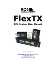
2.0 User Manual Revision 1.3 July 2005 JDS Soundsculpture - Solid State of the Arts.TM 1-866-258-4577 www.theatrewireless.com Disclaimers WIRING AND INSTALLATION OF BATTERIES, DIMMERS, AND LOADS MUST BE IN ACCORDANCE WITH APPLICABLE LOCAL AND NATIONAL ELECTRICAL CODES. Soundsculpture devices and equipment are operated at the user’s own risk and Soundsculpture Incorporated accepts no liability, either direct or consequential, arising from the use of this equipment. Not For Use Where Human Safety May Be At Risk The Soundsculpture RC4 radio system has not been evaluated by any safety agency for use where human safety may be at risk. Soundsculpture Incorporated accepts no liability if RC4 equipment is used for such purposes. Not For Control of Pyrotechnical Devices Soundsculpture RC4 receivers should not be used to control pyrotechnical devices. A brief output surge on dimmer outputs during power-up could trigger these devices. Soundsculpture Incorporated accepts no liability if RC4 equipment is used for such purposes. Product Safety RC4-TXD-Series transmitters are designed to meet or exceed applicable UL, CSA, and CE standards. They pass the dielectric withstand test (hipot) to 3000VAC, use UL- and/or CSA-listed components where required, and are packaged in a grounded metal chassis. A Special Inspection label applied by the Electrical Safety Authority (ESA) of Ontario, Canada, is available on request. The RC4-RX4-Series receiver/dimmers are capable of controlling very large currents at 12VDC. They should not be allowed to operate at a dangerous temperature. Appropriately sized wire and connectors must be used, along with suitable ventilation and external fuses rated for the load being operated. Additional information is provided in this manual. Soundsculpture devices and equipment are operated at the user’s own risk and Soundsculpture Incorporated accepts no liability, either direct or consequential, arising from the use of this equipment. Soundsculpture RC4 Operation Manual Page 2 of 41 RC4 USER MANUAL – TABLE OF CONTENTS Disclaimers ................................................................................................................................................................................. 2 Not For Use Where Human Safety May Be At Risk ............................................................................................................... 2 Not For Control of Pyrotechnical Devices .............................................................................................................................. 2 No 3rd-Party Safety Certification ............................................................................................................................................. 2 RC4 2.0 System Overview ......................................................................................................................................................... 4 Getting Started – Setting Up RC4 Components ...................................................................................................................... 5 Items You Do NOT Need to Get Started ................................................................................................................................. 5 Parts of the RC4 System.......................................................................................................................................................... 5 Transmitter .............................................................................................................................................................................. 5 Receivers ................................................................................................................................................................................. 6 TXD-Series Transmitter Operation ......................................................................................................................................... 7 The TXD-Series User Interface – Overview ........................................................................................................................... 7 TXD-Series Keypad Map ........................................................................................................................................................ 8 The Main Screen – Watch Channels ....................................................................................................................................... 8 Set DMX Start – Block of Contiguous Channels .................................................................................................................... 9 Edit Individual DMX and CV Channel Assignments ............................................................................................................ 10 Save DMX Setup .................................................................................................................................................................. 11 Recall DMX Setup ................................................................................................................................................................ 11 Transmitter Channel Test Functions...................................................................................................................................... 12 RX4 Dimmer Settings (Done at Transmitter) ........................................................................................................................ 14 Select Receiver RX Number / Display Receiver Status (Battery Voltage) ............................................................................ 14 Set RX Channel Assignments ............................................................................................................................................... 15 Set Other RX Parameters ...................................................................................................................................................... 16 RX Setup Copy / RX Setup Paste.......................................................................................................................................... 17 Send RX Config .................................................................................................................................................................... 18 RX4 Receiver Operation ......................................................................................................................................................... 19 RX4 Receiver Buttons and Indicators ................................................................................................................................... 19 Changing the RX Number ..................................................................................................................................................... 20 Default Settings ..................................................................................................................................................................... 21 Dimmer Power Wiring and Fusing........................................................................................................................................ 22 RX4 Receiver Power Connection Diagram ........................................................................................................................... 23 RX4-HO High Output Receivers........................................................................................................................................... 25 RX4-MINI Receivers ............................................................................................................................................................ 27 RX4-STANDARD Typical Wiring Diagram ........................................................................................................................ 29 RX4-STANDARD / RX4-HO Typical High-Power Wiring Diagram .................................................................................. 30 Receiver Load Testing – Receiver Test Buttons ................................................................................................................... 31 Receiver Battery Voltage Indication ..................................................................................................................................... 31 Radio Settings .......................................................................................................................................................................... 32 Set System ID ....................................................................................................................................................................... 32 Set System Baud Rate ........................................................................................................................................................... 33 Additional System Parameters .............................................................................................................................................. 33 Setting the System ID............................................................................................................................................................ 33 Using Other Channels ........................................................................................................................................................... 34 Complete LAWNII Configurations for the RC4 System ....................................................................................................... 34 RX4-MINI Lawn-II RF Module Setup .................................................................................................................................. 35 A General Discussion of Radio Reliability ............................................................................................................................. 36 Troubleshooting ....................................................................................................................................................................... 37 Simple Solutions to Common Problems ................................................................................................................................ 37 Reset and Initialize to Factory Defaults ................................................................................................................................ 39 RC4 Specifications ................................................................................................................................................................... 40 Soundsculpture RC4 Operation Manual Page 3 of 41 RC4 2.0 System Overview The RC4 2.0 wireless dimmer system is an enhanced 4th-generation digital system for operating theatrical lighting, motors, and solenoids. It offers improved performance over previous Soundsculpture systems, with more channels and a user interface that allows receivers to be configured remotely from the transmitter. Spread-spectrum RF technology ensures a secure, robust, and high-speed wireless link between all system components, and does not require special licensing for use anywhere in North America. The TXD-Series rack mount transmitter is a digital DMX device, compliant with the USITT DMX512/1990 (4uSec) standard. Eight 0-10V control voltage inputs are also provided, using on-board analog-to-digital converters. Thirty-two and sixty-four channel models are currently available. Up to 128 RX-4 receivers can be configured and managed from the transmitter, providing up to 512 individual dimmers. RX4-STANDARD receivers are for use with 12VDC battery power and provide four pulse-widthmodulated (PWM) dimmer outputs, each capable of delivering 150W into any kind of load (typically halogen lamps). Each dimmer can be individually assigned to any RC4 channel. Outputs assigned to the same channel can be externally wired in parallel to drive large loads. The total power handling of the RX4STANDARD is limited to 500W by the capacity of the printed-circuit board traces and connector pins; components are substantially over-rated to ensure a long life. RX4-HO high-output receivers are similar to standard receivers but have a higher power capacity thorough heavier copper on the printed-circuit board, a cooling fan, and larger MOSFET components (the power transistors that do the work). Each HO dimmer can deliver 250 watts, with a maximum power limit for the entire receiver of 1000W. For small spaces, the RX4-MINI is half the size of the other RX4 receivers. Ideal for tiny props or hiding in costumes, the MINI receiver can deliver 50 watts per channel, with a maximum power limit of 200W. The electronic assembly of the RX4-MINI can be removed from its chassis for even more flexibility when mounting in very small props or costumes. Soundsculpture RC4 Operation Manual Page 4 of 41 Getting Started – Setting Up RC4 Components Items You Do NOT Need to Get Started RC4 systems ship with some extra items that are not needed to get started, including: 12VDC power adaptor Short 25-pin D-Sub data adaptor cable Various extra connector shells, pins, etc. Put these items in a safe place where they can be found in the future. More information about the power and data adaptors can be found in the Radio Settings section of this manual. Parts of the RC4 System The RC4 system consists of a rack-mount transmitter, transmitter transceiver, and one or more receivers. Before the system can be used, each item must be properly set up and connected. Transmitter The receiver is a 4-inch deep 3U rack chassis. Control signals are sent to a remote spread-spectrum radio transceiver via a supplied 9-foot 25-pin D-Sub cable, and this transceiver communicates with radiodimmers on stage. The 25-pin cable carries both power and data to the transceiver. Connect the rack chassis to the transceiver with this cable, and position the transceiver so the top surface is facing out on the theatre stage. NOTE: The transceiver antenna is under the top surface of the case, as indicated on the transceiver label. The spread-spectrum radios of the RC4 system will work through walls and other barriers to a distance of several hundred feet. This range will be reduced, however, by the density of obstructions, other radio activity in the 907 - 921Mhz band, and wide-band interference generated by nearby lamps, motors, etc. (including loads connected to RC4 receivers themselves). Line-of-sight from the transmitter transceiver to each RX4 receiver is great where possible, but is not essential. Soundsculpture RC4 Operation Manual Page 5 of 41 Connect a DMX source to the DMX input on the transmitter. The RC4-TXD-series DMX input is not terminated. A terminated cable or in-line termination connector must be used if termination is required (i.e. the transmitter is at the end of the DMX line). In general, a 120-ohm resistor between pins 2 and 3 of a DMX connector will provide adequate termination. Analog 0-10V control voltage (CV) inputs are also provided. These inputs are indicated on the LCD as CV1 to CV8, with levels displayed similarly to DMX levels. The input impedance of the analog CV inputs is 20K-ohms. It is best to drive these inputs with a low-impedance source. DMX and CV inputs can be mapped to dimmers in any combination and used simultaneously. Receivers Each receiver must be set up with a charged 12V battery and up to 4 lamps or other loads. For most applications, all of this can be done with a single 10-pin connector. Please review the Receiver Operation section of this manual for pin-out details and other information. Output channel assignments are configured from the transmitter. Radio and dimmer control electronics will not operate properly with less than 10V of incoming power. This voltage must be maintained under load. Choose appropriately sized batteries and keep them charged. Soundsculpture RC4 Operation Manual Page 6 of 41 TXD-Series Transmitter Operation The TXD-Series User Interface – Overview The TXD-Series radio transmitter user-interface consists of a 16-key keypad, a 20-character x 2-line LCD display, and a rotary control. The rotary control can also be pressed as a button, usually the equivalent of the Select / Enter key. Twelve of the keypad keys are used to select a function or function-group: The green keys invoke transmitter DMX channel assignment settings. The yellow keys invoke receiver settings. The blue keys are test functions. The bottom 4 keys include Exit to escape any previously invoked function, generic user-interface functions Left/-/No and Right/+/Yes, and the Select / Enter key. In some cases, the screen will show a number of parameters on screen. The Left/-/No and Right/+/Yes keys move the cursor between parameters, and the blinking cursor indicates the parameter that is active for editing with the rotary control. The value of the selected parameter is adjusted by turning the rotary control. In most cases, the new value is saved by pressing the Enter button on the keypad, or pressing the rotary control knob. In other cases, as when adjusting RX receiver parameters before sending them to a receiver, values will remain as displayed while you navigate the screen. In some modes, as when editing a DMX/CV Assignment, the Left/-/No and Right/+/Yes keys increment or decrement a specific value on the screen, usually the RF channel (-/+). This is the case when there are only two parameters on screen – one adjusted with the rotary control and the other with the -/+ buttons. To escape any mode and return to the main Watch Channels screen, press EXIT. Soundsculpture RC4 Operation Manual Page 7 of 41 TXD-Series Keypad Map Set DMX Contiguous Block Start Channel Edit Individual DMX and CV Channel Assignments Save DMX Setup Recall DMX Setup Select Receiver RX Number / Get RX Status Set RX Channel Assignments Set Other RX Parameters Send RX Config Copy RX Setup to Scratchpad Paste RX Setup from Scratchpad Manual Channel Test Auto-Chase Channel Test Exit / Watch Channels Move Left / Decrement / No Move Right / Increment / Yes Select/ Enter The Main Screen – Watch Channels The TXD-Series transmitter powers up to the Watch Channels screen. Using settings recalled from eeprom memory, the system immediately begins “spooling” the selected DMX and CV channels to the radio link. When RC4-RX4 radio-dimmers see data with the correct system ID and channel, they respond as programmed. In Watch Channels mode, the transmitter display is a channel monitor showing the current real-time value of any DMX or CV input. The rotary control selects the channel being displayed by rolling through 512 DMX channels and 8 CV channels – a total of 520 possible settings. If the displayed channel is assigned to a radio channel, the assignment is displayed. To get to a distant numeric value more quickly, the Left/-/No and Right/+/Yes keys change the currently displayed channel in increments of 10 channels up and down, skipping the CV channels (use the rotary control to select CV channels). Soundsculpture RC4 Operation Manual Page 8 of 41 Set DMX Start – Block of Contiguous Channels The quickest and easiest way to assign DMX channels to radio dimmers is to use a contiguous block of channels. In this case, only the first channel need be specified. CV inputs cannot be assigned this way, but can be added by editing individual assignments afterward (more information below). Press Set DMX Start, select the desired first DMX channel with the rotary control, then press the rotary control button or Enter key. A series of contiguous DMX channels will now be assigned to radio channels and the display will confirm the range. When first entering this mode, the DMX channel currently being watched is displayed as the starting channel. You may change this by turning the rotary control. If the first DMX channel is set higher than 481, assignments will wrap around to channel 0. CV channels will not be assigned in this mode. This action overwrites the current DMX channel assignments. It does not affect saved DMX Setups. Soundsculpture RC4 Operation Manual Page 9 of 41 Edit Individual DMX and CV Channel Assignments To create a more sophisticated channel map where assignments are not contiguous and/or CV inputs are also used, press the Edit DMX/CV Assigns key. In this mode, the rotary control sets the DMX / CV source, while the Left/-/No and Right/+/Yes keys select the target rf channel. When a desired combination is displayed, press the Enter key or rotary control button to save the new assignment. Only one source can be assigned to each target rf channel. Similar to Watch Channels mode, the rotary control will select CV inputs above DMX 512 and below DMX 1. This makes it easy to assign any of the 8 available CV inputs to any rf dimmer channel, with the rotary control providing access to 520 sources (512 DMX channels and 8 CV channels). … HINT: Use the Set DMX Start function (detailed above) to create a map that is close to what you need. Then use the Edit Assigns key to add CV channels or otherwise adjust your channel assignments. Soundsculpture RC4 Operation Manual Page 10 of 41 Save DMX Setup Note: Current channel assignments are maintained even if you don’t save them in a DMX Setup. Save and Recall of DMX Setups is provided to facilitate switching between different channel maps you may need for different shows, theatres, etc. Three DMX/CV channel assignments can be saved in eeprom. Each set of assignments is called a DMX Setup, even though they may also include CV inputs. To save the current assignments you have created using the Set DMX Start and/or Edit DMX/CV Assigns functions, press Save DMX Setup. Use the rotary control to select the destination memory location 1-3, then press the Enter key or the rotary knob to execute the save. … Upon execution, any previously stored settings in the selected memory location are overwritten. When the save is complete, you are returned to Watch Channels mode. Recall DMX Setup Note: Current channel assignments are maintained even if you don’t save them in a DMX Setup. Save and Recall of DMX setups is provided to facilitate switching between different channel maps you may need for different shows, theatres, etc. To recall an assignment map for current use, press Recall DMX Setup. Use the rotary control to select the source memory location 1-3. Press the Enter key or the rotary knob to execute the recall. Upon execution, previous settings are overwritten with the settings from memory. Soundsculpture RC4 Operation Manual Page 11 of 41 Transmitter Channel Test Functions It is often desirable to test dimmers at times when DMX data is not available. The RC4-TXD-Series transmitter provides two very useful options to accomplish this. DMX and CV inputs are not interrupted when test modes are invoked, normal data transmission continues. Only the channel currently being tested is overridden. Test modes could, therefore, be used intentionally during a running show. It is important to be aware of any incoming DMX or CV data that may appear on live dimmers, even when a test mode is being used. Manual Channel Test Invoked by pressing the Manual Channel Test button, this mode allows a radio dimmer channel to be manually faded up and down. The channel is selected using the Left/-/No and Right/+/Yes keys. The level is adjusted in real-time with the rotary control. In addition, three levels of control resolution are provided: coarse (25-step increments), medium (5-step increments), and fine (1-step increments). Pressing the rotary control button cycles through these three options. The Manual Channel Test screen indicates the control resolution (c, m, or f), current level (0 – 255), current rf dimmer channel and corresponding DMX or CV input channel, and whether of not this channel will chase (Yes or No). The Chase parameter is used by the Channel Chase Test function described below. It is toggled between Yes and No for the currently displayed rf channel by pressing the Select/Enter key. Escape test mode by pressing the Exit key. Soundsculpture RC4 Operation Manual Page 12 of 41 Channel Chase Test RC4-TXD-Series transmitters also feature a built-in chaser, ideal for testing a series of RC4 dimmer channels automatically and continuously. The chase process smoothly fades up and down from zero to 255 and back to zero, stepping through channels with the Chase parameter enabled from Manual Channel Test mode. The speed of the chase is set with the rotary control. At the slowest speed, each channel fade is clearly visible and takes 3 to 4 seconds. At the fastest speed, channel stepping occurs at approximately 4 channels per second. Select which channels will be part of the chase by pressing the Manual Channel Test key and making changes there. You can then return to the chase by pressing Channel Chase Test. It is not necessary to press Exit between these modes. Escape test mode by pressing the Exit key. Soundsculpture RC4 Operation Manual Page 13 of 41 RX4 Dimmer Settings (Done at Transmitter) Each RX4 radio-dimmer watches for two different kinds of data packets coming from the transmitter: - dimmer levels - control/setup information In either case, the correct system ID must be in the packet or the data will be ignored. Channel assignments and other settings for each radio dimmer are made at the transmitter, then uploaded to the corresponding receiver by using the Send RX Config function. Dimmer configurations are stored both in the target receiver and in eeprom memory in the transmitter. This makes it easy to create all your receiver configurations in advance, even if you do not have all your receivers powered up and “live”. Select Receiver RX Number / Display Receiver Status (Battery Voltage) Receivers are identified by their RX number, ranging from RX001 through RX128. To select a radio-dimmer for configuration, press Select RX. The block cursor will blink over the RX number on the transmitter LCD. Use the rotary control to set the RX number. As you scroll through RX numbers, the transmitter looks for live receivers. When it finds one, an “A” is displayed beside the RX number on the transmitter LCD to indicate the presence of an Active receiver. For any Active receiver, at any time, you can press and hold the Select RX button to display status information including the firmware version and current battery voltage. If no Active receiver is found, this is also reported. OR It is not necessary to press Enter. This is also true for all other receiver parameters BUT these values do not take effect until they are sent to a live dimmer unit. Press Exit to return to Watch Channels mode. NOTE: Some receivers may contain customized firmware for special applications. A specific RXnum is required to activate these custom processes. For example, a custom dual-motor speed control might be activated by using RX128. Customized receivers usually default to their special functions if defaults are loaded using the receiver’s recessed buttons. Refer to the documentation supplied with your customized receiver for additional information about your specific unit. Soundsculpture RC4 Operation Manual Page 14 of 41 Set RX Channel Assignments Each RC4-RX4 radio-dimmer has four outputs. These outputs can be assigned to any rf control channel. First you must select the RX number to be edited using the Select RX function. You can proceed to modify the configuration for this receiver regardless of whether or not it is powered up and Active. The receiver must be powered on and Active, however, before you can successfully upload your configuration to that receiver. All configuration settings are stored in the transmitter as well as each receiver, allowing you to do all your configuration programming before you set up your receivers. To assign dimmers to specific rf control channels, press Assign RX Chans. The screen will indicate the selected RX number, the currently assigned control channels for the four outputs (top line of the LCD), and the corresponding DMX channels in the current DMX Setup (which can also include CV inputs). If the currently selected receiver is live and Active, the transmitter will retrieve and display current internal settings. Otherwise, the transmitter will use the settings stored in eeprom. RX-4 receivers running firmware 2.200 or higher provide two different user-selectable dimmer curves: Linear, and Inverse Square Law. Earlier firmware versions offer only the Linear curve. If the control channel number is preceded by a “d” on the display, the channel is configured as a linear dimmer. If the channel number is preceded by an “s”, the dimmer is configured as a switch (see Switch Mode below for additional information). If the control channel number is preceded by an “i" on the display, the channel is configured for inverse square law dimming. Inverse square law dimming is ideal for use with LEDs, providing a very smooth highresolution output that looks great even at the low end of the dimmer range. (cursor is here) dimmer dimmer rf chan 5 rf chan 6 Receiver RX012 (not Active) DMX 240 DMX 241 switch rf chan 9 DMX 241 dimmer rf chan 32 CV 8 d = linear dimming (ideal for incandescent and halogen lamps) i = inverse square law dimming (ideal for LEDs) s = switch output (ideal for solenoids, inverters, and other non-dim loads) Press the Exit key to escape back to Watch Channels mode. Note: The corresponding DMX/CV channels will change if the current DMX Setup is changed. Soundsculpture RC4 Operation Manual Page 15 of 41 Set Other RX Parameters In addition to a channel assignment, dimmer outputs have other parameters, as outlined below. These parameters can be edited by pressing Set RX Params and moving the cursor with Left/-/No and Right/+/Yes keys. The value under the cursor can be edited by turning the rotary control. (cursor is here) dimmer dimmer rf chan 5 rf chan 6 Receiver RX012 (not Active) Low Level 5 24 switch rf chan 9 5 (ignored) dimmer rf chan 32 5 Low Level Limit Each dimmer output has a range of 255 dimmer levels, implemented as a PWM (pulse-width modulation) signal at a base frequency of 75Hz. In some cases, large loads draw excessive currents for brief periods when driven at low power levels. This is because PWM applies full power for a short slice of time (1/255 of 75Hz, approx. 52us) at the lowest level and longer slices of time as power levels increase (up to 255/255, fully on). In some cases, short spikes at the lowest levels are stressful for the dimmer and can create electrical noise and interference that is undesirable for both the radio-dimmer and nearby equipment. For example, a large motor will remain stalled, and a large lamp filament will remain cold and unlit, until a significant amount of energy is delivered. In these states, large transient spikes are being generated 75 times each second. The Low Level Limit parameter ensures that power levels below a selected limit are reduced to zero. For large loads, a recommended Low Level Limit is 15 (15/255). For small loads a limit of 5 or less can be used. The available range is 2 to 31. Low Level has no effect in switch mode (details below). Switch Mode In some cases, dimmed power levels are not desirable. When turning on a relay or powering a DC device that requires clean constant power, a dimmer output can be set for switch mode. In this case, dimmer levels of 127 or lower will turn the output off, while levels of 128 or higher will turn the output on. (Thus, Low Level limits, which are well below 127, have no effect in switch mode.) Normally – even when using an output in dimmer (not switch) mode – a DMX level of zero will turn the channel fully off and a DMX level of 255 will turn the channel fully on. But in some cases, particularly where CV channels are used, levels do not always stay at zero or 255, and small amounts of noise or flutter are common. Any amount of data flutter could cause a PWM dimmer level to be invoked. This is avoided by selecting Switch Mode. Each output can be set for dimmer or switch mode. Soundsculpture RC4 Operation Manual Page 16 of 41 NOTE: Soundsculpture TXD-Series transmitters and RC4 receivers are fully digital, making channel flutter highly unlikely. Nonetheless, flutter could get into DMX data before it arrives at the transmitter, and flutter on analog CV inputs is common. Data Timeout Period (not user adjustable) For various reasons, rf dimmer data could be interrupted. When this happens, dimmer outputs will be maintained at their last known value for one second while the receiver waits for valid data to reappear. This one-second period is not user adjustable. If no good data has been received in this period, all dimmer levels are cleared to zero. The 32-channel TX32D transmits 32 rf channel levels approximately 60 times per second. This gives receivers 60 opportunities to capture new rf data before dimmer levels blink out. In reality, the RC4 radio link is robust enough that single data packets are seldom lost, never mind 60 in a row. Visible effects of radio interference are virtually non-existent with the RC4 system. The DMX512/1990 specification published by the United States Institute for Theatre Technology requires DMX devices to have a loss of data tolerance of not less than 1 second. Soundsculpture TXD-Series transmitters have a loss of data tolerance of just over 1 second on DMX inputs. There is no correlation or relationship between the DMX loss of data timeout, and the RC4 Data Timeout Period. A Faulty DMX link leads to the former; radio interference leads to the latter. RX Setup Copy / RX Setup Paste When configuring many receivers, several are often programmed identically or very similarly. To speed the process of setting up and programming these receivers, an RX Setup scratchpad memory is provided. From any RX Setup screen (invoked with the Select RX, Assign RX Chans, and Set RX Params keys), all current settings can be saved to the scratchpad be pressing RX Setup Copy. All parameters are saved, including those not currently displayed. For example, Low Level cut-off values are not displayed from the RX Chans screen, but Low Level settings are still written to the scratchpad when the Copy key is pressed. Similarly, the settings currently in scratchpad memory can be recalled to overwrite the currently displayed RX setup by pressing RX Setup Paste. All parameters are overwritten, including those not currently displayed. Use the Select RX key and rotary control to select source and destination RX numbers for Copy and Paste. Soundsculpture RC4 Operation Manual Page 17 of 41 Send RX Config When the Send RX Config key is pressed, all settings for the selected RX number – dimmer channel assignments, Low Level limits, and switch mode settings – are uploaded by radio to the corresponding RX4 radio-dimmer. At the same time, and regardless of the presence of an Active receiver, settings are backed up to eeprom memory in the transmitter. If the corresponding receiver is not Active, the transmitter LCD will report RXxxx Not Found. Otherwise, the LCD will report Setup Confirmed. The confirmation process verifies every parameter sent, while also retrieving the receiver firmware version, current battery voltage, and more. OR A radio-dimmer will assume a new RX number if it receives a control packet while the Set RX recessed button is held down. In this case, the RX value of that packet will become the new RX number for that receiver. Subsequent control packets for this RX number will be accepted and acknowledged with no need to hold down the Set RX button. (See the Receiver Operation section for additional information.) In a properly functioning system, it is never necessary to use the Set RX button on a receiver. Every receiver should have its own RX number for the entirety of its service life. The only time the Set RX function should be used is when adding a new receiver to an existing system, or resetting a receiver after default settings have been loaded. NOTE: The correct System ID must be programmed in the receiver or no data will be accepted, regardless of the state of the SetRX button. Soundsculpture RC4 Operation Manual Page 18 of 41 RX4 Receiver Operation RX4 Receiver Buttons and Indicators As noted in previous sections, RX4 radio-dimmer are configured and controlled remotely from a TXDSeries transmitter, using the transmitter’s user interface. This is the only way to configure each output, selecting the dimmer channel, switch or dim mode, and Low Level limit. Inside the plastic receiver enclosure are two circuit boards: the radio board, and the dimmer board. The RX4 receiver has a simple user-interface intended to help with wiring and load testing, and restoring internal settings to default values. Various LEDs indicate the status of the dimmer and radio boards. On the dimmer board there are five recessed push buttons, four function LEDs, and four additional LEDs directly connected to the four dimmer outputs. From left to right, the switches and function LEDs on the RX4-STANDARD and RX4-HO are: Button: Output 4 Test Button: Output 3 Test Button: Output 2 Test / Power Up Load Default Settings Button: Output 1 Test / Assume RX Number of Incoming Setup Packet LED: Setup Data Receive Indicator (green) LED: Dimmer Level Receive Indicator (green) LED: Computer Operating Properly (COP) / Battery Voltage Indicator LED: Data Error Indicator (red) Reset Button: Hardware Reset / System Restart Soundsculpture RC4 Operation Manual Page 19 of 41 Changing the RX Number To change the RX number of a receiver, send a configuration from the transmitter using the RX number you desire, while simultaneously holding down the Assume RX Number button on the receiver (4th button from the left). The RX number of the sent data packet will be assumed by the receiver and stored in eeprom. The receiver MUST be powered on and Active during this process. The radio board must be programmed with the correct system number. Subsequent configurations for this RX number will be accepted without holding any button down. When a receiver accepts new configuration data, it displays a short “light show” acknowledgement on its four LEDs. It also sends a digital acknowledgement back to the transmitter. The light show is displayed if a configuration message comes in for the current RX number, or if a configuration message comes in while the Assume RX Number button is down. In the latter case, the new RX number becomes the current RX number for future configurations. NOTE: Some receivers may contain customized firmware for special applications. A specific RXnum is required to activate these custom processes. For example, a custom dual-motor speed control might be activated by using RX128. Customized receivers usually default to their special functions if defaults are loaded using the receiver’s recessed buttons. Refer to the documentation supplied with your customized receiver for additional information about your specific unit. Soundsculpture RC4 Operation Manual Page 20 of 41 Default Settings To restore receiver default settings, hold down the recessed Test Out 2 / Set Def button while powering up the receiver or pressing the recessed Reset* button immediately to the left of the Data Error LED. This will load the following settings: RX Number = 1 Output 1 Assigned Output 2 Assigned Output 3 Assigned Output 4 Assigned to to to to rf rf rf rf Channel Channel Channel Channel 1, 2, 3, 4, Dimmer Dimmer Dimmer Dimmer Mode, Mode, Mode, Mode, Lo-Level Lo-Level Lo-Level Lo-Level Limit Limit Limit Limit 5 5 5 5 To change these settings, send a new configuration from the transmitter. It is likely that you will also need to restore the RX number to a value other than RX001. If so, follow the procedure in the proceeding section. NOTE: Some receivers may contain customized firmware for special applications. A specific RXnum is required to activate these custom processes. For example, a custom dual-motor speed control might be activated by using RX128. Customized receivers usually default to their special functions if defaults are loaded using the receiver’s recessed buttons. Refer to the documentation supplied with your customized receiver for additional information about your specific unit. * This is NOT the protruding reset button on the rear of the radio, which resets only the radio board. Soundsculpture RC4 Operation Manual Page 21 of 41 Dimmer Power Wiring and Fusing WIRING AND INSTALLATION OF BATTERIES, DIMMERS, AND LOADS MUST BE IN ACCORDANCE WITH APPLICABLE LOCAL AND NATIONAL ELECTRICAL CODES. Beside the main power connector on RX4 receiver-dimmers is a pair of clips for a load fuse. Standard AGC fuses fit easily into these clips. This fuse is in the positive side of the dimmer output circuit. To effectively protect the load, wiring, and electronics, and to reduce potential hazards, one of the following dimmer fusing techniques MUST be used: 1. Choose a load fuse that accurately reflects the total load for all four channels. This technique is best when loads are relatively small, i.e. one MR16 on a single channel. 2. Use external fuses for each individual output, appropriately sized for each load. Put the fuse in the positive side of the load circuit, returning directly to the positive side of the supply battery, rather than the positive output terminals on the dimmer. RX4 dimming is done on the negative side. This option is recommended for high currents. A small fuse should still be installed on the RX4 board to drive the indicator LEDs. A positive lead must still come to the receiver to power the logic circuitry. DO NOT OPERATE LOADS WITHOUT FUSES. YOU MUST FUSE EVERY CIRCUIT. DO NOT simply install the largest fuse you can find and forget about it. This can result in an unsafe situation, possibly a fire or burn hazard. It is not recommended to internally fuse any RX4 receiver above 25A. DO NOT fuse any single RX4 dimmer above 25A. With all 4 dimmers individually fused at 25A, a total of 100A can flow. At 12V this is 1200W, substantially beyond the maximum rating of the product. Continuous current exceeding 500W requires the RX4-HO receiver. In any case, be sure to use appropriate connectors and large wire gauges, and monitor the system closely – particularly the operating temperature – at all times. Here are some typical fuse values: 75 watt MR16 halogen lamp: draws 6.25A at 12VDC. Use an 8A fuse. 1/4HP 12VDC motor: typically draws 20A when operated smoothly, but could surge to 40A on a fast start-up. Use a 25A fast-blow fuse and avoid rapid start-up (ramp up the power level slowly). Do not use slow-blow fuses. They do not protect semiconductors in a fault condition. It is difficult to apply typical safety standards to these devices, because of the unusual circumstances of theatrical prop construction. The “rule of thumb” is that nothing should be allowed to operate at a dangerous temperature. Appropriately sized wire gauges and connectors must be used, along with suitable ventilation and external fuses rated for the load being operated. WIRING AND INSTALLATION OF BATTERIES, DIMMERS, AND LOADS MUST BE IN ACCORDANCE WITH APPLICABLE LOCAL AND NATIONAL ELECTRICAL CODES. RC4 devices are operated at the user’s own risk and Soundsculpture accepts no liability, either direct or consequential, arising from the use of RC4 equipment. Soundsculpture RC4 Operation Manual Page 22 of 41 RX4 Receiver Power Connection Diagram The RX4-STANDARD is remarkably versatile and powerful for its small size. Four outputs deliver pulsewidth-modulated power capable of driving high current motors, lamps, and other inductive or resistive loads. Each output is rated for 150W, equivalent to approximately 12.5amps at 12 volts. The four outputs can be combined in any combination to drive larger loads, to a maximum of 500W into a single load (40A). Total receiver power handling is limited by circuit-board traces (copper trace thickness and width) and connector pins. For higher power handling, use the RX4-HO (high output) which is directly interchangeable with the RX4-STANDARD and can deliver up to 1000W (with caution, and adequate ventilation). The recommended AMP tool for these connector pins is 90124-2. Shells, pins, and tools are available from most electronic component suppliers, including www.digikey.com, or from Soundsculpture Incorporated. Channels connected in parallel must have their channel-select and Low Level limit switches set identically to avoid one channel taking a heavy load on its own. Damage resulting from inappropriate configurations will not be covered under warranty. WIRING AND INSTALLATION OF BATTERIES, DIMMERS, AND LOADS MUST BE IN ACCORDANCE WITH APPLICABLE LOCAL AND NATIONAL ELECTRICAL CODES. Soundsculpture RC4 Operation Manual Page 23 of 41 The RX4-STANDARD and RX4-HO (high output) receivers includes a 6-pin auxiliary power input connector: Pins 1, 3, and 5 are wired in parallel with pin 1 on the 10-pin connector. This is +V in. Pins 2, 4, and 6 are wired in parallel with pin 2 on the 10-pin connector. This is GND in. In some cases, the 6-pin connector can be used for high-power battery input, while the 10-pin connector can be used just for outputs. If all pins of both connectors are used, eight wires are available for both power in and dimmer out. This results in symmetrical current carrying capacity on both sides of the dimmers. Some models of RX4 receiver include an optional 2-pin logic battery connection. Pin 1 is positive (+), pin 2 is negative (-). This connector can be used as a 12V unregulated power output to external electronics, or be used for a 12V lead-acid battery or large storage capacitor. This allows the logic and RF circuitry in the RC4 receiver to continue functioning even if the load-bearing batteries run down. If a non-rechargeable battery is used with this connector, it should be protected from reverse current with a diode. Significant output currents are present on this connector. Soundsculpture RC4 Operation Manual Page 24 of 41 RX4-HO High Output Receivers The high output (HO) version of the RX4 receiver features upgraded MOSFET power components and a cooling fan. Even with these enhancements, high-current power handling can be dangerous and should not be sustained indefinitely. At 12VDC, a 1000W load demands over 80 Amps of power. The batteries, wires, connections, and fuses required to handle this kind of load are very large. WIRING AND INSTALLATION OF BATTERIES, DIMMERS, AND LOADS MUST BE IN ACCORDANCE WITH APPLICABLE LOCAL AND NATIONAL ELECTRICAL CODES. To accommodate large loads, both the RX4-STANDARD and the RX4-HO feature a 6-pin auxiliary power input connection. Used together with the 10-pin power input/output connector, there are four separate connections in parallel to bring power in, and another four to carry power out to the load(s). Thus, each wire and connection can carry up to 20A at 12V, provided it is of an appropriately large gauge. The fuse on RX4 receiver boards cannot carry 80 Amps. When wiring large loads, the positive (+) side of the circuit should be completely external to the RX4 receiver, and it should be carefully and safely fused. A small-gauge wire can be used to bring the positive supply to the RX4 internal control electronics, and the fuse on the RX4 can be 1A or even smaller, since it will only supply the indicator LEDs. All RX4 dimmers introduce pulse-width modulation on the negative (-) side of the circuit, acting as a dimmer on the negative line to the load. This is where you need heavy wire and you should utilize all 4 input and output connections across both power connectors. If you are using the RX4 as one large dimmer on a single channel, you can wire the outputs of each channel in parallel. For this to work effectively, circuit impedance and resistance for each channel must be closely controlled. More current will flow through shorter circuits, thicker wires, and tighter connections, and this can cause more than a fair share of the total load to be flowing through a particular dimmer channel. This kind of overloading causes overheating and damage that is not covered under warranty, and can be a fire hazard. For optimal safe performance, resistances of each parallel circuit should be as close to identical as possible. Beware of faulty or worn connectors adding substantial resistance. Soundsculpture RC4 Operation Manual Page 25 of 41 Damage caused by not configuring parallel channels identically is not covered under warranty, and can be a fire hazard. When ganging output channels together, they must be set to the same data channel, and have the same Low Level cut-off value. Otherwise, one or more channels could switch off while other channels are still operating, causing damage to channels that remain on and causing too much current to flow through single conductors and connections. It is also advised to set the Low Level cut-off quite high when loads are large. This prevents high EMI/RFI when dimmers attempt to drive a cold filament or stalled motor. Before using any RX4 receiver at high power levels, please re-read this manual and double-check your choices of battery, wire, fuses, and connectors. Nothing should run hot; if something does run hot, it is under-rated or improperly applied and should be replaced with a component that does not run hot. If the receiver itself is running hot, then either: - additional ventilation is required running time is too long (it needs time to cool off) load current are too high any combination of the above DO NOT continue to operate the receiver under these conditions. WIRING AND INSTALLATION OF BATTERIES, DIMMERS, AND LOADS MUST BE IN ACCORDANCE WITH APPLICABLE LOCAL AND NATIONAL ELECTRICAL CODES. Be careful –high power loads are operated at your own risk, and Soundsculpture cannot be held responsible for any damages whatsoever, whether direct of consequential. Soundsculpture RC4 Operation Manual Page 26 of 41 RX4-MINI Receivers Shown here in black, the RX4-MINI is available in other colors as well. The RX4-MINI is the smallest, most portable receiver for the RC4 wireless dimming system. It can be used in small props, costumes, and anywhere else with limited space. Just like the larger RX4STANDARD and RX4-HO receivers, the RC4-MINI provides up to four channels of dimming. It is configured from an RC4-TXD-Series transmitter, just like the other RC4 receivers. Summary of Differences Between the RX4-MINI and the RX4-STANDARD The block diagram from the RX4-MINI is nearly identical to the diagram for the RX4-STANDARD, but it does not include auxiliary power inputs. The circuit board traces in the RX4-MINI are narrower and cannot carry as much current. To save space, the MOSFET power drivers do not have heat-sinks. For both of these reasons, the current handling of the MINI receiver is substantially less than other RC4 receivers. Programming and diagnostics of the radio module in the MINI receiver requires a special 4-pin adaptor. This adaptor is detailed later in this manual. (Most users will never need to configure their radio modules.) Because of a lack of space in the MINI receiver, the radio antenna is mounted in one end of the enclosure, below the cover. Over long distances, better radio performance may result when this end of the receiver is facing towards the transmitter rf tranceiver. Over typical distances, antenna position will have no affect on performance, provided the antenna is not blocked by metal or batteries (this is also true for other RC4 receiver models). The antenna end of the enclosure is clearly marked on the unit. Connections and Wiring The RX4-MINI 10-pin power connector has the same pin-out as the standard power I/O connector on other RC4 receivers. No auxiliary power connector is provided. Maximum power handling is 50W per channel, 200W maximum. When running at maximum power, it is recommended to limit the maximum time the channel is activated to avoid overheating. Soundsculpture RC4 Operation Manual Page 27 of 41 The highest fuse rating that should ever be used in a MINI receiver is 16A. In practice, the smallest appropriate fuse should be used for the connected load(s) and will typically be much smaller than 16A. If you are running a single 50W MR15 lamp, use a 5A fuse. Use fast-blow fuses to protect the power driver electronics. WIRING AND INSTALLATION OF BATTERIES, DIMMERS, AND LOADS MUST BE IN ACCORDANCE WITH APPLICABLE LOCAL AND NATIONAL ELECTRICAL CODES. Configuring Channels Programming channels, Low Level cut-off, and dimmer/switch mode is done the same way for all RC4 receivers. Buttons and LEDs The positions of the recessed buttons and LEDs are different but clearly marked on the unit. The same functions and indications are provided. Soundsculpture RC4 Operation Manual Page 28 of 41 RX4-STANDARD Typical Wiring Diagram Soundsculpture RC4 Operation Manual Page 29 of 41 RX4-STANDARD / RX4-HO Typical High-Power Wiring Diagram Soundsculpture RC4 Operation Manual Page 30 of 41 Receiver Load Testing – Receiver Test Buttons All RX4 receivers have a channel test button for each on-board dimmer. These buttons are recessed to avoid accidental activation and can be pressed with any slender object. Test buttons override incoming levels only while pressed. Any combination of the four channels may be tested simultaneously. Receiver firmware 2.200 or higher provides a fade up to 100% when a test button is pressed. Previous firmware versions switch the channel on to 75% of maximum level. Receiver Battery Voltage Indication The Computer Operating Properly (COP) blinking LED on RC4-RX4 receivers also indicates battery voltage. At 10.5V or higher, this LED is green and blinks slowly. Below 10.5V it is red and blinks rapidly. These voltage thresholds have been selected with rechargeable lead-acid batteries in mind. A 12V leadacid battery should never be discharged below 10V or it will be chemically damaged, leaving it unable to fully recharge to original capacity. RC4 receivers manufactured after July 2005 will operate without radio dropouts on battery voltage down to 8V. Older units operate down to 10V. An for older units is available on request and is recommended for use with NiCad or NiMH batteries. When using RX4-STANDARD or RX4-HO receivers, an auxiliary logic battery can be used to ensure radio and logic circuitry continues to operate when the load battery is severely discharged. Soundsculpture RC4 Operation Manual Page 31 of 41 Radio Settings Some RC4 system settings reside in the radio modules used at each end of the wireless link – the transmitter transceiver and the radio boards in the receivers. These settings are stored in EEPROM memory and do not require adjustment under normal circumstances. Nonetheless, it may some day be necessary to adjust a System ID or other parameter. This is done using an RS-232 data terminal, or terminal emulator software on a PC with a COM port. When making changes to radio settings, power and data connections must be made at the rear of the transceiver or receiver unit (with the exception of the RC4-MINI receiver, detailed later in this manual). A 12VDC power adaptor, along with a short 25-pin D-Sub adaptor cable are required. These items are supplied with your RC4 system but are rarely (if ever) used. Do not attempt to change system settings while powering the receiver from the 10-pin RC4 power connection. This powers both the radio board and the dimmer logic board, and does not leave the radio board available for data on the rear 25-pin port. The data cable observes RS-232 standards with data on pins 2/3, handshaking on pins 4/5/6/20, and common on pin 7. Readily available cables can be used if the supplied cable is lost or damaged. Note that RC4 radios never require configuration under normal circumstances. Set System ID The System ID is a number from 0 to 65535. Values below 1000 are reserved for older 16-channel RC3 systems. RC4 systems are assigned System IDs of 1000 or higher. Every RC4 user is assigned a unique System ID when their system is shipped, and a database of these numbers is carefully managed and maintained. To avoid data collision with other users, system numbers should NOT be changed. Some users have multiple RC4 systems, however, and may wish to change the System ID in receivers to move between systems. Do not change a transmitter System ID without authorization from Soundsculpture Incorporated. Do not use System IDs not assigned to you. Soundsculpture RC4 Operation Manual Page 32 of 41 Set System Baud Rate The default baud-rate for 32-channel systems is 38.4kbps (kilobits per second). Additional System Parameters Each radio module must be configured for proper operation in the RC4 architecture. Each System ID should have only one transmitter (master), and any number of receivers (slaves). To assist advanced users, the LAWNII User’s Manual accompanies this manual. The radio settings used for the RC4 system create a low-latency master-slave network with no built-in acknowledgements or retries. This is because normal acknowledgement and handshaking protocols sacrifice timing for accuracy and can cause unexpected delays in data transmission. For real-time control systems, different techniques must be used. The microprocessors at each end of the RC4 dimmer control system use real-time cyclical-redundancy to ensure reasonable accuracy without introducing varying delays. The coding for this technique is proprietary to the Soundsculpture RC4 system. LAWNII settings can be made using an RS232 terminal, or a PC running a terminal emulation program with a COM port. It is important that the terminal emulator be able to send control characters (i.e. Ctrl-C). The Microsoft Windows Operating system comes bundled with the HyperTerminal terminal emulation program. It can be used to configure LAWNII radios. Be sure to use the following settings: Direct connect to any available COM port VT100 emulation Control keys act as Terminal keys (very important) Standard ASCII character set Additional information about connecting to the LAWNII radio with HyperTerminal is included in the LAWNII radio manual. Some users of LAWNII systems have had difficulty using HyperTerminal, with no problems using other terminal emulators. If HyperTerminal does not work for you, please try an alternative emulator program. Setting the System ID The System ID of each LAWNII radio must be the same for the transmitter and all receivers used in a single RC4 system. If you own and use more than one RC4 radio system, you may wish to move receivers between systems. This can be done by changing only one parameter (SYS) in the LAWNII radio. All other settings can be left unchanged and do not need to be re-entered: <connect at 38400 baud> <Ctrl-C three times to enter command mode> SYS <use number for your system> SAVE <allow at least 500ms for save to complete> TRANS To avoid conflicts, Soundsculpture RC4 systems use System IDs of 1000 or higher. Soundsculpture RC4 Operation Manual Page 33 of 41 Using Other Channels At the factory, all RC4 LAWNII transceivers are set up on radio channel 2 (CHA 2). LAWNII radios support three channels (1, 2, and 3) and any of these may be used with the RC4 system. If another channel is used, this setting must be changed at every LAWNII in the system – the transmitter and each receiver. Note: If you are using multiple RC3 systems and experience reduced refresh rates as they try to share radio bandwidth, try changing the channel of one system. If you are using 2 systems, run them on channels 1 and 3 to keep the as far apart in the radio spectrum as possible. Complete LAWNII Configurations for the RC4 System For a single Transmitter (TX) LAWNII: AUTOLF ON ABAUD 38400 * MYC RC4TX DFCN RC4TX SYS <number for your system> CHA 2 <other channels can be used> PACTIME A 1 BE E 0 UNPROTO RC4RX LAWNGRAM ON TRANSGRA ON LCALLS RC4TX PACLEN 0 TIMEOUT 0 SAVE <allow at last 500ms for save to complete> TRANS For any number of Receiver (RX) LAWNIIs: AUTOLF ON ABAUD 38400 * MYC RC4RX DFCN RC4RX SYS <use number for your system> CHA 2 <other channels can be used> PACTIME A 1 BE E 0 UNPROTO RC4TX LAWNGRAM ON TRANSGRA ON LCALLS RC4RX PACLEN 0 TIMEOUT 0 SAVE <allow at last 500ms for save to complete> TRANS Soundsculpture RC4 Operation Manual Page 34 of 41 * If you are not already connected at 38400 baud, you will have to reconnect to the LAWNII radio at this speed after setting ABAUD 38400. New LAWNII radios are configured at the default baud rate of 9600, so initial connections must be made at this speed. The RC4 dimmer system requires a baud rate of 38400. The transmitter and any associated receivers MUST have the same SYS and CHA settings of they will not communicate with one another. RX4-MINI Lawn-II RF Module Setup Connection to the radio module in the RX4-MINI is made through a small 4-pin Amp MTA-100-series header beside the main power connector. An adaptor allows connection to a terminal or computer COM port, and a source of power. The header is Amp 640456-4. It mates with any Amp MTA-100 4-pin connector. The specific part number varies with wire gauge being used; a suitable part for 26AWG wire is Amp 640442-4. Pinout: Pin 1: GND / Serial Data Common Pin 2: 12VDC Pin 3: RS-232 Data Receive (RX) Pin 4: RS-232 Transmit Data (TX) This is a 3-wire RS-232 interface with no handshaking. With working data and power connections, radio configuration is the same as for other RC4 receivers. Note that RC4 radios never require configuration under normal circumstances. Soundsculpture RC4 Operation Manual Page 35 of 41 A General Discussion of Radio Reliability The Soundsculpture RC4 system is exceptionally reliable when properly set up. The most critical factor when using the system is transceiver and receiver placement, since these units house the high-frequency spread-spectrum antenna. Consider the following guidelines when installing the transmitter and all receivers: - The antenna surfaces must not be obstructed by metal objects. Remember that lead-acid batteries have lead inside, and count as an obstruction. - Internal antennas are most effective when facing other units in the system (i.e. receivers should face towards the transmitter and vice-versa). Alternatively, all antennas can face in the same direction (up, down, into a wing, etc.); reflections off ceilings and walls usually result in a solid radio link. - Avoid many solid obstructions between the transmitter and receivers, especially as the distance between them is extended. In an environment with a continuous solid reflective surface (like a ceiling) and a minimum of obstructions (no walls), RC4 spread spectrum receivers work flawlessly over thousands of square feet. With transceivers facing each other directly and unobstructed line-of-sight, point to point range can exceed 3000 feet. A typical theatre environment with the transmitter transceiver secured overhead, and receivers on stage (less than 100 feet away) is ideal. No user-detectable errors should occur, regardless of electrical noise from nearby equipment. Flying set pieces in the house area should also perform correctly via reflections off the stage floor (i.e. the chandelier in The Phantom of the Opera). Errors will generally not sustain more than 1/60th of a second, the maximum amount of time before every channel has been reset by redundant data transmissions. However, if errors are caused by consistent multipath interference or insufficient signal level, problems may persist or repeat. The RC4 software protocol has been designed to be tolerant of the kinds of interference and interruptions that are typical of RF data links. Moderate interference should not cause user-detectable errors. Soundsculpture RC4 Operation Manual Page 36 of 41 Troubleshooting The RC4 system is VERY tolerant of radio signal degradation and electrical noise. Most users have no problems... in fact, at the time of this writing only one radio interference problem has ever been reported with an RC4 system, and was corrected when the transmitter was moved away from an unusually noisy lamp. If you think you are suffering from radio interference problems, FIRST be absolutely certain your batteries are good. Simple Solutions to Common Problems Problem: When channel levels are brought up, the load (lamp, motor, etc.) operates for a brief moment then goes off. A second or so later, it comes back on. The problem appears cyclical or intermittent. Cause: When a lead-acid battery is measured with no load it reads approximately 12V. This is true even for a substantially discharged battery. RC4 electronics require very little current to operate, and a discharged battery still provides enough power for the receiver to come on and indicate traffic. Here’s the problem cycle: 1. When RF control data indicates an output level, the output driver delivers battery power to the load. If the battery is under-rated or under-charged, voltage will drop substantially under load. 2. When the battery voltage drops below 8V the RC4 receiver will shut down. This disconnects the load from the battery. 3. With the load disconnected, battery voltage drifts back up. (It eventually drifts back up to 12V, unless the battery is seriously damaged). When battery voltage climbs above 9V, the RC4 receiver comes back on and starts monitoring control data again. ...And the cycle starts all over again. In some cases, exactly the same symptoms are caused by undersized wire or poor connections between the battery and the RC4 receiver. These cause resistance, resulting in a voltage drop at the receiver when the load increases (Ohm’s Law). This cycle through steps 1, 2, 3 and back to 1 results in the symptom described. The actual cycle time varies with battery size, battery charge, the size of the load, power levels selected, and wire sizes used. Eventually the battery is damaged and fails to drift back up enough to continue the cycle. To prove this is happening, put a volt-meter across the power input terminals at the RC4 receiver. The voltage will drop when the load comes on. When the voltage drops enough, the load will go off. When the voltage drifts back up enough, the load will switch back on. If these voltage fluctuations are apparent at the receiver but not at the battery terminals, then wire and connections are at fault – you must conduct adequate current from the battery to the receiver to avoid these unwanted voltage drops. Soundsculpture RC4 Operation Manual Page 37 of 41 Solution: Ensure the battery is fully charged using a smart charger that accurately indicates the condition of the battery. Be sure the battery is rated large enough for the intended load for the operating time you require. Be sure wire gauges are large enough, especially between the battery and the receiver/dimmer. Be sure connections are tight and strong. Hot wires or connections are probably causing problems. Problem: Fades are not smooth, channels intermittently black-out for a second or more. Cause: The RC4 system depends on RF signals getting from the transmitter to the receivers. An antenna is under the top cover of each 7” x 4” x 2” enclosure -- one at the transmitter, and one in each receiver. The RC4 system operates in the 907 – 921Mhz range using spread-spectrum digital radio. Although output power is quite low, high frequency signals bounce easily and receivers are very sensitive. This means that receivers can find good data most of the time. The system will not work, however, if the tops of the plastic enclosures are blocked with batteries or metal coverings. Signals must be able to get in and out of the top of each box, both at the transmitter and at each receiver. Solutions: Make sure the top area of each plastic enclosure is not blocked by batteries or metal obstructions. These block radio signals. Small clusters of wiring, gridwork, bars across the top of the enclosures, etc. generally DO NOT cause problems. Make sure there is a path for SOME signal to get through and the system should work fine. Where quasi-line-of-sight is attainable: 1. Position the transmitter tranceiver overhead, above the stage or other area where receivers are positioned. The top of the transceiver should be facing down, towards the receivers. 2. Position receivers facing up, towards the transmitter tranceiver. Where line-of-site cannot be acheived, or there are numerous obstructions between transmitter and receiver: 1. Position the transmitter transceiver so the top of the box is facing the ceiling above the stage. Signals will bounce back down and flood the stage. Avoid metal obstructions or large harnesses of wiring in the signal path. 2. Position receivers so the top of each box is facing the ceiling of the stage. Reflected signals will bounce directly into the receiver antennas. The RC4 system is VERY tolerant of signal degradation and electrical noise. Most users have no problems... in fact, at the time of this writing only one radio interference problem has ever been reported with an RC4 system, and the problem was corrected when the transmitter was moved away from an unusually noisy lamp. If you think you're suffering radio interference problems, FIRST be absolutely certain your batteries are good. Soundsculpture RC4 Operation Manual Page 38 of 41 Problem: You need to operate two or three RC4 systems in close proximity without interference. Out of the box, systems do not directly address each other's receivers but responsiveness is clearly degraded. Cause: RC4 radios have 3 radio channels available, but most systems are set for the default channel 2. To ensure the fastest response time with the largest number of channels, almost all available radio bandwidth of a channel is used by a single system. When two systems try to share bandwidth on the same radio channel, both systems perform poorly. Even when this happens, multiple RC4 systems cannot directly address each other's receivers because they have different digital System IDs. Solution: Set nearby RC4 systems to operate on different channels. When operating two systems, set them to operate on channels 1 and 3. We do not recommend operating more than 3 RC4 systems in close proximity. Problem: You only have one RC4 system but you suspect there might be another one operating nearby. Solution: Radio power and sensitivity of RC4 transceivers are tuned for good performance within most interior spaces, with little chance of signals getting outside a building, or into an adjacent building. There is always a possibility, however, of interference between spaces within a single facility. If you suspect there is another RC4 user within radio range, change your radio channel. At the time of this writing, the need for such measures has never been reported by any RC4 user. Reset and Initialize to Factory Defaults All transmitter internal memories can be cleared to factory defaults by powering on the unit while holding down the Set DMX Start and EXIT buttons together. The LCD will ask you to confirm, do so by pressing Right/+/Yes. WARNING: This action overwrites all eeprom memory, including DMX Setups and RX Configurations. Soundsculpture RC4 Operation Manual Page 39 of 41 RC4 Specifications RC4 RF Specifications RF Channels: 3 Transmit Power: 13 dbm, typical Sensitivity: -96 dbm, typical Frequency: - Channel 1: 907.45 MHz - Channel 2: 914.81 MHz (default, used for most systems) - Channel 3: 921.10 MHz Modulation: FSK, spread-spectrum No. Chips per bit: 16 Bit Rate (raw): 76.8 Kb/sec Protocol: AX.25 Repeater: 7 Range: - 300 feet typical indoors - 3000 feet typical unobstructed outdoors RF Module Power Consumption: 200mA at 12V DC Operating Temperature: 0º to +50ºC FCC License: Approved by FCC and DOC (Canada), no user license required RC4-TXD-Series Transmitter Specifications Input Power: AC115V 60Hz 0.5A DMX Input: USITT DMX512/1990 (4uSec) Analog CV Inputs: 0 – 10V x 8 channels, 20K-ohm input impedance RC4 Dimmer Specifications RC4-RX4 Standard Continuous current, per channel: 12.5A (150W) Intermittent peak current, per channel: 20A (240W) 1 Total current, sum of all channels: 42A (500W) 1 Over-Current Protection on Dimmer Outputs: YES Over-Temperature Protection on Dimmer Outputs: YES Maximum input voltage: 15V, 12V typical Minimum input voltage: 9V Suitable for inductive loads (motors, solenoids, etc.): YES RC4-RX4-HO (High Output) Continuous current, per channel: 21A (250W) Intermittent peak current, per channel: 30A (360W) 1 Total current, sum of all channels: 83A (1000W) 1 Maximum input voltage: 15V, 12V typical Minimum input voltage: 9V Suitable for inductive loads (motors, solenoids, etc.): YES Soundsculpture RC4 Operation Manual Page 40 of 41 RC4-RX4-MINI Continuous current, per channel: 5A (60W) Intermittent peak current, per channel: 8A (100W) Total current, sum of all channels: 17A (200W) Over-Current Protection on Dimmer Outputs: YES Over-Temperature Protection on Dimmer Outputs: YES Maximum input voltage: 15V, 12V typical Minimum input voltage: 9V Suitable for inductive loads (motors, solenoids, etc.): LIMITED 2 1 Wiring instructions must be closely followed and adequate ventilation must be provided. Individual circuits must each be individually protected with fast-blow fuses. 2 Can be used with small inductive loads with the addition of an external back-EMF snubber diode. Specifications subject to change without notice. Soundsculpture assumes no liability or responsibility for safe operation of receivers, dimmers, batteries, wiring, fuses, and/or any other components or materials that may be connected or in proximity. Safe operation of high-current systems is the sole responsibility of the purchaser and/or user. Soundsculpture - Solid State of the Arts.TM Soundsculpture Incorporated 1-866-258-4577 [email protected] www.theatrewireless.com Soundsculpture RC4 Operation Manual Page 41 of 41