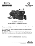
1
ADVANTAGE
POOL PUMPS
MASTERFLOW OWNER’S MANUAL
INSTALLATION, OPERATION & PARTS
To prevent potential injury and to avoid unnecessary service calls, read this manual
carefully and completely.
CAUTION – We highly recommend a qualified professional install and
service this product.
WARNING – This manual contains important safety information that must
be furnished to the end user of this product. FAILURE TO READ AND
FOLLOW ALL INSTRUCTIONS COULD RESULT IN SERIOUS INJURY.
SAVE THIS INSTRUCTION MANUAL
624 South B Street • Tustin, CA 92780
Toll Free: 800.636.8866 • Tel: 714.505.1166 • Fax: 714.505.1160
advantageman.com
IMPORTANT SAFETY INSTRUCTIONS
Before installing or servicing this electrical equipment, turn power supply OFF.
Basic safety precautions should always be followed, including the following: Failure to follow
instructions may result in injury.
This is the safety-alert symbol. When you see this symbol on your pump manual, look for one
of the following signal words and be alert to the potential for personal injury.
WARNING warns about hazards that could cause serious personal injury, death or major
property damage and if ignored presents a potential hazard.
CAUTION warns about hazards that will cause or can cause minor or moderate personal
injury and/or property damage and if ignored presents a potential hazard. It can also make
consumers aware of actions that are unpredictable and unsafe.
The NOTICE label indicates special instructions that are important but not related to hazards.
WARNING – Read and follow all instructions in this
owner’s manual and on equipment. Failure to follow
instructions can cause severe injury and/or death.
WARNING – Incorrectly installed or tested equipment may fail, causing severe injury or
property damage.
Read and follow instructions in owner's manual when installing and operating equipment. Have a trained pool
professional perform all pressure tests.
1. Do not connect system to a high pressure or city water system.
2. Use equipment only in a pool or spa installation.
3. Trapped air in system can cause explosion. BE SURE all air is out of system before operating
or testing equipment.
Before pressure testing, make the following safety checks:
• Check all clamps, bolts, lids, and system accessories before testing.
• Release all air in system before testing.
• Tighten trap lids to 30 ft. Ibs. (4.1 kg-m) torque for testing.
• Water pressure for test must be less than 25 PSI (7.5 kg/cm2).
• Water Temperature for test must be less than 100° F. (38° C).
• Limit test to 24 hours. After test, visually check system to be sure it is ready for operation.
Remove trap lid and retighten hand tight only.
2
INSTALLATION
Only qualified, licensed personnel should install pump and wiring.
Pump mount must:
Be solid – Level – Rigid – Vibration free. (To reduce vibration and pipe stress, bolt pump to mount.)
Allow pump suction inlet height to be as close to water level as possible.
Allow use of short, direct suction pipe (To reduce friction losses).
Allow for gate valves in suction and discharge piping.
Have adequate floor drainage to prevent flooding.
Be protected from excess moisture.
Allow adequate access for servicing pump and piping.
NOTICE – Use Teflon tape for making all threaded connections to the pump. Do not use pipe dope;
pipe dope will cause stress cracking in the pump.
NOTICE – Pump suction and discharge connections have molded in thread stops. DO NOT try to
screw pipe in beyond these stops.
Teflon Taping Instructions:
Use only new or clean PVC pipe fittings.
Wrap male pipe threads with one to two,layers of Teflon tape. Cover entire threaded portion of pipe.
Do not overtighten or tighten past thread stop in pump port!
If leaks occur, remove pipe, clean off old tape, rewrap with one to two additional layers of tape
and remake the connection.
NOTICE – Support all piping connected with pump!
Piping:
Use at least 2” (51 mm) IPS PVC pipe. Increase size if a long run is needed.
To avoid strains on the pump, support both suction and discharge pipes independently.
Place these supports near the pump.
To avoid a strain left by a gap at the last connection, start all piping at the pump and run pipe away
from the pump.
Never use a suction pipe smaller than pump suction connection, To avoid airlocking, slope suction
pipe slightly upward toward the pump.
NOTICE – To prevent flooding when removing pump for service, all flooded suction systems must
have gate valves in suction and discharge pipes.
Fittings:
Fittings restrict flow; for best efficiency use fewest possible fittings.
Avoid fittings which could cause an air trap.
Pool fittings must conform to International Association of Plumbing and Mechanical Officials
(IAPMO) standards.
Use only non-entrapping suction fitting or double suction.
3
ELECTRICAL
Ground motor before connecting to electrical power supply. Failure to ground
motor can cause severe or fatal electrical shock hazard.
Do not ground to a gas supply line.
To avoid dangerous or fatal electrical shock, turn OFF power to motor before working on
electrical connections.
Ground Fault Circuit Interrupter (GFCI) tripping indicates an electrical problem. If GFCI trips
and will not reset, have a qualified electrician inspect and repair electrical system.
Exactly match supply voltage to nameplate voltage. Incorrect voltage can cause fire or seriously
damage motor and voids warranty. If in doubt consult a licensed electrician.
Voltage
Voltage at motor must be not more than 10% above or below motor nameplate rated voltage or motor may
overheat. causing overload tripping and reduced component life. If voltage is less than 90% or more than 110%
of rated voltage when motor is running at full load, consult power company.
Bonding Lug
Grounding/Bonding
Install, ground, bond and wire motor according to local or National
Electrical Code requirements.
Green
Ground
Screw
Permanently ground motor. Use green ground terminal provided under
motor canopy or access plate (See Fig. 1); use size and type wire required
by code.
Connect motor ground terminal to electrical service ground.
Figure 1 – Typical ground screw and
bonding lug locations
Bond motor to pool structure. Use a solid copper conductor, size No.8 AWG
(8.4 sq.mm) or larger. Run wire from external bonding lug (see Fig. 1) to
reinforcing rod or mesh.
Connect a No.8 AWG (8.4 sq.mm) solid copper bonding wire to the pressure
wire connector provided on the motor housing and to all metal parts of the swimming pool, spa, or hot tub and
to all electrical equipment, metal piping or conduit within 5 feet (1.5 m) of the inside walls of swimming pool,
spa, or hot tub.
Wiring
Pump must be permanently connected to circuit. If other lights or appliances are also on the same circuit, be
sure to add their amp loads to pump amp load before figuring wire and circuit breaker sizes. (If unsure how to
do this or if this is confusing, consult a licensed electrician.) Use the load circuit breaker as the master on-off
switch.
Install a Ground Fault Circuit Interrupter (GFCI) in circuit; it will sense a shortcircuit to ground and disconnect
power before it becomes dangerous to pool users. For size of GFCI required and test procedures for GFCI,
see manufacturer's instruction.
In case of power outage, check GFCI for tripping (which will prevent normal pump operation). Reset if necessary.
NOTICE: If you do not use conduit when wiring motor, be sure to seal wire opening on end of motor to
prevent dirt, bugs, etc., from entering
4
OPERATION
NOTICE: NEVER run pump dry. Running pump dry may damage seals,
causing leakage and flooding. Fill pump with water before starting motor.
Before removing trap cover:
1. STOP PUMP before proceeding.
2. CLOSE GATE VALVES in suction and discharge pipes.
Hazardous suction.
Can trap hair or
body parts, causing
severe injury or
death.
Do not block suction.
3. RELEASE ALL PRESSURE from pump and piping system.
4. NEVER tighten or loosen clamp while pump is operating.
If pump is being pressure tested, release all pressure before removing trap
cover.
Do not block pump suction. To do so with body may cause severe or fatal
injury. Small children using pool must ALWAYS have close adult
supervision.
Priming Pump
Release all air from filter and piping system: see filter owner’s manual.
In a flooded suction system (water source higher than pump), pump will prime itself when suction and
discharge valves are opened.
If pump is not in a flooded suction system, unscrew and remove trap cover; fill trap and pump with water.
Lubricate trap cover “0” Ring with petroleum jelly each time it is removed.
Clean and inspect “0” Ring; reinstall on trap cover.
Replace trap cover on trap; turn clockwise to tighten cover.
NOTICE: Tighten trap cover by hand only (no wrenches)! Use a wrench only if necessary to remove lid!
Pump should prime now. Priming time will depend on vertical length of suction lift and horizontal length of
suction piping.
If pump does not prime, make sure that all valves are open, suction pipe end is under water, pump suction is
below water level, and that there are no leaks in suction pipe. See Troubleshooting Guide, Page 12.
Routine Maintenance
The only routine maintenance needed is inspection/cleaning of trap basket.
Debris or trash that collects in basket will choke off water flow through the pump. Follow instructions
below to clean trap:
1. Stop pump, close gate valves in suction and discharge, and release all pressure from system
before proceeding.
2. Unscrew trap lid (turn counterclockwise). If necessary, use a lever such as a board or long
screwdriver between lugs on trap cover.
5
OPERATION (CONT.)
3. Remove strainer basket and clean. Be sure all holes in basket are clear, flush basket with water and
replace in trap with large opening at pipe connection port (between ribs provided). If basket is
replaced backwards cover will not fit on trap body.
4. Clean and inspect “0” Ring; reinstall on trap cover.
5. Clean “0” Ring groove on trap body and replace lid. To help keep lid from sticking, hand tighten
only {no wrenches!}.
6. Prime pump (see priming instructions, above).
Draining Pump
1. Pump down water level below all inlets to the pool.
To avoid dangerous or fatal electrical shock hazard, turn OFF power to motor
before draining pump.
2. Remove trap cover and use low pressure air to blow accumulated water from the piping
system. Lugs have been provided on the trap lid to use a lever or pry bar for loosening.
3. Cap inlet piping after draining to keep water out of the pipes.
4. To prevent pump from freezing, remove the trap cover and drain the tank body through the
two drain plugs. Clean pump thoroughly; replace trap cover.
NOTICE: Tighten trap cover by hand only (no wrenches)! Use a lever or wrench only if
necessary to remove cover! If pump is not anchored, use caution to not break attached piping!
5. Be sure motor is kept dry and covered.
Storage/Winterizing:
WARNING – Explosion hazard. Purging the system with compressed air can cause
components to explode, with risk of severe injury or death to anyone nearby. Use only a low pressure
(below 5 PSI), high volume blower when air purging the pump, filter, or piping.
NOTICE: Allowing pump to freeze will damage pump and void warranty!
NOTICE: Do not use anti-freeze solutions (except propylene glycol) in your pool/spa system. Propylene
glycol is non-toxic and will not damage plastic system components; other anti-freezes are highly toxic and
may also damage plastic components in the system.
Drain all water from pump and piping when expecting freezing temperatures or when storing pump for a
long time (see instructions below).
Keep motor dry and covered during storage.
To avoid condensation/corrosion problems, do not cover pump with plastic.
6
OPERATION (CONT.)
For outdoor/unprotected installations:
1. Gravity drain system as far as possible.
2. Protect areas which retain water with non-toxic propylene glycol antifreeze (“RV antifreeze”).
3. Enclose entire system in a weatherproof enclosure.
4, To avoid condensation/corrosion damage, allow ventilation; do not wrap system in plastic.
5. Use a 40% propylene glycol/60% water solution to protect pump to -50 degrees F (-46 degrees C).
Startup For Winterized Equipment
1. Remove any temporary weather protection placed around system.
2. Follow filter manufacturer’s instructions for reactivation of the filter.
3. Inspect all electrical wiring for damage or deterioration over the shutdown period. Have a
qualified serviceman repair wiring as needed.
4. Inspect and tighten all watertight connections.
5. Open all valves in suction and return piping.
6. Remove any winterizing plugs in piping system.
7. Drain all antifreeze from system.
8. Close all drain valves and replace all drain plugs in piping system.
9. Prime pump according to instructions.
7
PUMP SERVICE
Pump should only be serviced by qualified personnel.
Be sure to prime pump before starting.
Before removing trap cover:
1. STOP PUMP before proceeding.
2. CLOSE GATE VALVES in suction and discharge pipes.
3. RELEASE ALL PRESSURE from pump and piping system.
4. NEVER tighten or loosen clamp while pump is operating.
To avoid dangerous or fatal electrical shock hazard, turn OFF power to motor before working on
pump or motor.
Aside from lubricating trap cover O-Ring, no lubrication or regular maintenance is needed beyond reasonable
care and periodic cleaning.
If shaft seal is worn or damaged, repair as follows:
Pump Disassembly/Removing Old Seal
Disconnect power to pump motor.
A Be sure gate valves on suction and return piping are closed before starting work.
Release all pressure by opening all vents before starting work.
1. Drain pump by removing drain plugs on bottom of pump body and trap body.
2. Be sure there is no pressure in trap body; remove cover (unscrew by turning
counterclockwise).
3. Remove clamp holding pump halves together. Motor and seal plate assembly can now be
pulled away from pump body.
4. Remove five screws and washers holding diffuser to seal plate. Remove diffuser.
5. Remove motor canopy. Being careful not to touch capacitor terminals, loosen capacitor
clamp and move capacitor to one side.
6. Hold shaft with 7/16” open-end wrench on motor shaft flats.
7. Unscrew impeller from shaft (turn counterclockwise when facing it).
NOTICE: On models with impeller screw, remove impeller screw (left hand thread – turn
clockwise) and gasket before removing impeller. Inspect gasket for damage, cracks, etc.
Replace if damaged.
8. Pull rotating member of seal off of impeller sleeve; clean sleeve.
9. Remove four screws holding seal plate to motor.
10. Place seal plate face down on flat surface and tap out ceramic seat.
11. Clean seal cavity in seal plate and clean motor shaft.
8
PUMP SERVICE (CONT.)
Pump Reassembly/Installing New Seal
1. Ceramic seat must be clean and free of dirt, grease, dust. etc. Wet outer edge with small
amount of liquid detergent; press ceramic seat into seal plate cavity firmly and squarely
with finger pressure.
2. If ceramic seat will not locate properly, remove it, place face up on bench and reclean
cavity. Ceramic seat should now locate.
3. If seat still will not locate properly, place a cardboard washer over the polished face and
use a piece of 3/4” (19mm) standard pipe for pressing purposes.
NOTICE: Be sure not to scratch or mar polished surface or seal will leak.
4. Remount seal plate on motor. Tighten bolts to
60-80 inch-lbs. (69-92 kg/cm) torque.
Seal Plate
Rotating Member
Polished (Drive Ring toward
Impeller)
Carbon
Face
5. Apply a small amount of liquid detergent to inside
diameter of rotating half of seal.
6. Slide rotating seal member, polished face last, over
impeller sleeve until rubber drive ring hits shaft
shoulder. (Fig. 2).
NOTICE: Be sure not to nick or scratch polished
seal face; seal will leak if face is damaged.
Ceramic Face
(Polished)
Figure 2
7. Screw impeller onto shaft (clockwise); this will
automatically locate seal in seal plate.
Shaft
Shoulder
Impeller
NOTICE: On models with impeller screw: install
impeller gasket and lock screw (left-hand thread –
turn counterclockwise). Torque lock screw to
50-55 inch-lbs. (57.6-63 cent.-kg.).
8. Mount diffuser on seal plate; tighten screws to 10-14 inch-lbs. (11.5-16.1 cent.-kg.) torque.
9. Assemble motor and seal plate to volute; be sure clamp is properly seated.
NOTICE: Clamp knob can be located in any position around volute; if it is moved after
assembly, tighten knob while tapping around clamp to assist sealing. Do not move clamp
while pump is full of water.
WARNING – Hazardous pressure. Release all pressure from pump and
piping system before working on pump or attempting to adjust or remove clamp.
Clamp may blow off of pump if adjusted under pressure.
10. Reinstall pump base mounting bolts (if used) and prime pump according to instructions.
9
PARTS LIST FOR MASTERFLOW PUMP
Pump Union
28
25
21
18
20
2A
3A
1A
27
15
26
2
24
23
3
19
4
17
10
13
5
22
11
6
6
7
8
9
Item
Part No.
Part Description
Item
Part No.
Part Description
2
3
4
5
6
7
8
9
10
11
13
15
56721
56722
56723
56724
56725
56726
56727
56728
56729
56730
56731
56732
Trap Lid
Trap Lid O-Ring
Trap Basket
Trap Body
Drain Plug w/ O-Ring
Flat Washer
Lock Washer
Nut
Gasket
Volute
Bolt for Diffuser
Diffuser
17
18
19
20
21
22
23
24
25
26
27
28
56733
56734
56735
56736
56737
56738
56739
56740
56741
56742
56743
56744
Band Clamp
Clamp Knob
O-Ring for Seal Plate
Mechanical Seal
Seal Plate
Base
Washer
Bolt 3/8-16x1”
Bolt 3/8-16x1-3/4”
Water Slinger
Impeller (Specify HP)
Motor (Specify HP)
10
TROUBLESHOOTING
WARNING – Read and understand safety and operating instructions in
this manual before doing any work on pump!
WARNING – Only qualified personnel should electrically test pump motor!
FAILURE TO PUMP; REDUCED CAPACITY OR DISCHARGE PRESSURE
Suction leaks/lost prime:
1. Pump must be primed; make sure that pump volute and trap is full of water. See priming
instructions.
2. Make sure there are no leaks in suction piping.
3. Make sure suction pipe inlet is well below the water level to prevent pump from sucking air.
4. Suction lift of 15 to 25 feet (4.5 to 7.5 meters) will reduce performance. Suction lift of more
than 25 feet (7.5 meters) will prevent pumping and cause pump to lose prime. In either case,
move pump closure (vertically) to water source. Make sure suction pipe is large enough.
Clogged pipe/trap/impeller, worn impeller:
5. Make sure suction trap is not clogged; if it is, clean trap and strainer.
6. Make sure impeller is not clogged.
7. Impeller and diffuser may be worn. If so, order replacement parts from Repair Parts List.
8. Pump may be trying to push too high a column of water. If so, a “higher head” pump is needed.
Electrical:
9. Pump may be running too slowly; check voltage at motor terminals and at meter while pump is
running. If low, see wiring instructions or consult power company. Check for loose connections.
10. Pump may be too hot.
A. Check line voltage; if less than 90% or more than 110% of rated voltage
consult a licensed electrician.
B. Increase ventilation.
C. Reduce ambient temperature.
D. Tighten any loose connections.
MECHANICAL TROUBLES AND NOISE
1. If suction and discharge piping are not adequately supported, pump assembly will be strained.
2. Do not mount pump on a wooden platform! Securely mount on concrete platform for quietest
performance.
11
LIMITED WARRANTY
Advantage Manufacturing warrants its new products to be free of workmanship and/or materials for a period
of 1 year from the date of installation or 18 months from the manufacturing date, whichever comes first, when
the product is used in a standard pool spa or jetted tub environment.
Advantage Manufacturing also provides additional limited warranties as follows;
• 2 years from manufacturing date on the Filter canister.
• 2 years from the date of purchase on the Lint pot canister and skid pack base.
This warranty excludes damage caused by freezing, misuse, acts of God or negligence and does not
include lids, connectors or O-rings.
The warranty does not cover:
• Items manufactured by other companies and installed on the Advantage Manufacturing
pump/filter systems.
• Problems resulting from but not limited to the following;
• Failure to comply with installation and operating instructions.
• Abuse, misuse, negligence, accident or damages that were beyond the control of Advantage
Manufacturing, Inc.
• Any and all alterations or modification to the product.
• Incidental, consequential, or other damages will not be paid by Advantage, Inc., including,
but not limited to the cost of labor and or water or chemical loss or any damages that occur.
• Damage cause by improper chemical treatment or corrosion.
• Damage caused by Acts of God or nature.
• Employment of the product for other than it’s intended use.
• Motor damage caused by improper electrical connections and/or the use of non-approved
extensions.
Obligations:
Advantage Manufacturing will, at its option, repair or replace the defective item at its own cost and expense.
Advantage Manufacturing is not responsible for any cost of shipping or transportation to or from our service
facility. Advantage Manufacturing is also not liable for any loss of time, inconvenience, incidental expenses,
labor and/or material charges incurred in connection with the removal or replacement of the equipment, or
any other incidental or consequential damages.
PRODUCT REGISTRATION
(Retain For Your Records)
DATE OF INSTALLATION
ADVANTAGE
POOL PUMPS
__________________________________________
INITIAL PRESSURE GAUGE READING (CLEAN FILTER) ________________
PUMP MODEL _____________________ HORSEPOWER ________________
FILTER MODEL ____________________________________________________
12