1
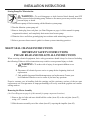
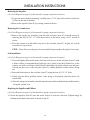
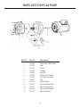
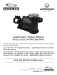
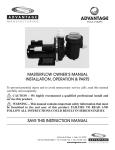
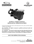
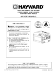
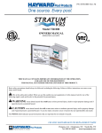
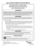
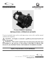
ADVANTAGE
POOL PUMPS
PC34 OWNER’S MANUAL
INSTALLATION, OPERATION & PARTS
To prevent potential injury and to avoid unnecessary service calls, read this manual
carefully and completely.
CAUTION – We highly recommend a qualified professional install and
service this product.
WARNING – This manual contains important safety information that must
be furnished to the end user of this product. FAILURE TO READ AND
FOLLOW ALL INSTRUCTIONS COULD RESULT IN SERIOUS INJURY.
SAVE THIS INSTRUCTION MANUAL
624 South B Street • Tustin, CA 92780
Toll Free: 800.636.8866 • Tel: 714.505.1166 • Fax: 714.505.1160
advantageman.com
IMPORTANT SAFETY INSTRUCTIONS
Before installing or servicing this electrical equipment, turn power supply OFF.
Basic safety precautions should always be followed, including the following: Failure to follow
instructions may result in injury.
This is the safety-alert symbol. When you see this symbol on your pump manual, look for one
of the following signal words and be alert to the potential for personal injury.
WARNING warns about hazards that could cause serious personal injury, death or major
property damage and if ignored presents a potential hazard.
CAUTION warns about hazards that will cause or can cause minor or moderate personal
injury and/or property damage and if ignored presents a potential hazard. It can also make
consumers aware of actions that are unpredictable and unsafe.
The NOTICE label indicates special instructions that are important but not related to hazards.
WARNING – Read and follow all instructions in this
owner’s manual and on equipment. Failure to follow
instructions can cause severe injury and/or death.
WARNING – This product should be installed and serviced only by a qualified professionals.
CAUTION – All electrical wiring MUST be in conformance with all applicable local codes,
regulations, and the National Electric Code (NEC).
ATTENTION INSTALLER – ThIS mANUAL CONTAINS ImpORTANT INFORmATION ABOUT
ThE INSTALLATION, OpERATION, AND SAFE USE OF ThIS pUmp ThAT mUST BE
FURNIShED TO ThE END USER OF ThIS pRODUCT. FAILURE TO READ AND FOLLOW ALL
INSTRUCTIONS COULD RESULT IN SERIOUS INJURY.
WARNING – To reduce risk of injury, do not permit children to use or climb on th is product.
Closely supervise children at all times. Components such as the filtration system, pumps, and heaters must be
positioned to prevent children from using them as a means of access to the pool.
CAUTION – This pump is intended for use on permanently installed swimming pools and may
also be used with hot tubs and spas if so marked. Do NOT use with storable pools. A permanently installed
pool is constructed in or on the ground or in a building such that it cannot be readily disassembled for storage.
A storable pool is constructed so that it is capable of being readily disassembled for storage and reassembled
to its original integrity. Though this product is designed for outdoor use. it is strongly advised to protect the
electrical components from the weather. Select a well-drained area, one that will not flood when it rains. It
requires free circulation of air for cooling. Do not install in a damp or non-ventilated location. If installed
within an outer enclosure or beneath the skirt of a hot tub or spa, adequate ventilation and free circulation of
air must be provided to prevent overheating of the motor.
2
IMPORTANT SAFETY INSTRUCTIONS
WARNING – Pool and spa components have a finite life. All components should be inspected
frequently and replaced at least every ten years, or if found to be damaged, broken, cracked, missing, or not
securely attached.
WARNING – Risk of Electric Shock. All electrical wiring MUST be in conformance
with all applicable local codes, regulations, and the National Electric Code (NEC). Hazardous
voltage can shock, burn, and cause death or serious property damage. To reduce the risk of electric
shock, do NOT use an extension cord to connect unit to electric supply. Provide a properly located
electrical receptacle. Before working on pump or motor, turn off power supply to the pump.
WARNING – To reduce the risk of electric shock replace damaged wiring immediately. Locate
conduit to prevent abuse from lawn mowers, hedge trimmers and other equipment.
WARNING – It is recommended to install a Ground Fault Circuit Interrupter (GFCI) in the circuit,
however, all electrical wiring MUST be in conformance with all applicable local codes, regulations, and the
National Electric Code (NEC).
WARNING – Failure to bond pump to pool structure will increase risk for electrocution and could
result in injury or death. To reduce the risk of electric shock, see installation instructions and consult a
professional electrician on how to bond pump. Also, contact a licensed electrician for information on local
electrical codes for bonding requirements.
Notes to the electrician: Use a solid copper conductor, size 8 or larger. Run a continuous wire from external
bonding lug to reinforcing rod or mesh. Connect a No.8 AWG (8.4 mm2) solid copper bonding wire to the
pressure wire connector provided on the motor housing and to all metal parts of swimming pool, spa, or hot
tub, and to all electrical equipment, metal piping (except gas piping), and conduit within 5 ft. (1.5m) of inside
walls of swimming pool, spa, or hot tub. ImpORTANT – Reference NEC codes for all wiring standards
including, but not limited to, grounding, bonding and other general wiring procedures.
WARNING – Suction Entrapment hazard.
Suction in suction outlets and/or
suction outlet covers which are damaged, broken, cracked, missing, or unsecured cause
severe injury and/or death due to the following entrapment hazards:
hair Entrapment – Hair can become entangled in suction outlet cover.
Limb Entrapment – A limb inserted into an opening of a suction outlet sump or suction outlet cover that is
damaged, broken, cracked, missing, or not securely attached can result in a mechanical bind or swelling of the
limb.
Body Suction Entrapment – A differential pressure applied to a large portion of the body or limbs can result
in an entrapment.
Evisceration/ Disembowelment – A negative pressure applied directly to the intestines through an unprotected
suction outlet sump or suction outlet cover which is damaged, broken, cracked, missing, or unsecured can
result in evisceration/disembowelment.
mechanical Entrapment – There is potential for jewelry, swimsuits, hair decorations, fingers, toes, or knuckles
to be caught in an opening of a suction outlet cover resulting in mechanical entrapment.
3
IMPORTANT SAFETY INSTRUCTIONS
WARNING – To Reduce the risk of Entrapment hazards:
– When outlets are small enough to be blocked by a person, a minimum of two functioning
suction outlets per pump must be installed. Suction outlets in the same plane (i.e. floor or
wall), must be installed a minimum of three feet (3’) [0.91 meter] apart, as measured from near point to near point.
– Dual suction fittings shall be placed in such locations and distances to avoid “dual blockage” by a user.
– Dual suction fittings shall not be located on seating areas or on the backrest for such seating areas.
– Never use pool or spa if any suction outlet component is damaged, broken, cracked, missing, or not securely
attached.
– Replace damaged, broken, cracked, missing, or not securely attached suction outlet components immediately.
– In addition to two or more suction outlets per pump installed in accordance with latest IAF (formerly NSPI)
standards and CPSC guidelines, follow all national, state, and local codes applicable.
– Installation of a vacuum release or vent system, which relieves entrapping suction, is recommended.
WARNING – hazardous pressure. Pool and spa water circulation systems operate
under hazardous pressure during start-up, normal operation, and after pump shut-off. Stand
clear of circulation system equipment during pump start-up. Failure to follow safety and
operation instructions could result in violent separation of the pump housing and cover due to
pressure in the system, which could cause property damage, severe personal injury, or death.
Before servicing pool and spa water circulation system, all system and pump controls must be in off position
and filter manual air relief valve must be in open position. Before starting system pump, all system valves
must be set in a position to allow system water to return back to the pool. Do not change filter control valve
position while system pump is running. Before starting system pump, fully open filter manual air relief valve.
Do not close filter manual air relief valve until a steady stream of water (not air or air and water mix) is
discharged from the valve. All suction and discharge valves MUST be OPEN when starting the circulation
system. Failure to do so could result in severe personal injury and/or property damage.
WARNING – Separation hazard. Failure to follow safety and operation instructions
could result in violent separation of pump components. Strainer cover must be properly secured
to pump housing with strainer cover lock ring. Before servicing pool and spa circulation system,
all system and pump controls must be in off position and filter manual air relief valve must be in
open position. Do not operate pool and spa circulation system if a system component is not assembled properly,
damaged, or missing. Do not operate pool and spa circulation system unless filter air relief valve body is in locked
position in filter upper body. All suction and discharge valves MUST be OPEN when starting the circulation system.
Failure to do so could result in severe personal injury and/or property damage.
WARNING – Never operate or test the circulation system at more than 50 PSI.
WARNING – Fire and burn hazard. Motors operate at high temperatures and if they are not
properly isolated from any flammable structures or foreign debris they can cause fires, which may cause severe
personal injury or death. It is also necessary to allow the motor to cool for at least 20 minutes prior to
maintenance to minimize the risk for burns.
WARNING – Failure to install according to defined instructions may result in severe personal
injury or death.
4
GENERAL INFORMATION
INTRODUCTION
This manual contains information for the proper installation and operation of the Advantage booster pump.
The instructions in this manual mUST be followed precisely. Failure to install according to defined
instructions will void warranty.
pRODUCT BENEFITS
• Pump is exceptionally quiet, and uses up to 40% less electricity than competitive booster pumps.
• Pump design allows for easy installation and service.
• Suitable for use with all pressure cleaners requiring a booster pump.
• Tall mounting base allows for increased motor ventilation as well as protection from flooding.
• Drain plug requires no tools for installation and removal.
• Volute may be re-oriented in the field for horizontal discharge.
• 1 year warranty.
5
INSTALLATION INSTRUCTIONS
WARNING – This product should be installed and serviced only by a qualified professional.
pUmp LOCATION
Typical Installation
Note: Plumb the booster
pump upstream of all air
inducing equipment
Min. of
3 feet
From Pool
Filtration
Pump
Pool
Filter
Heater
To
Spa
Booster
Pump
Plumbing
Options
1, 2 or 3
To
Cleaner
Solar
System
To
Pool
Chlorinator
Locate booster pump as shown in above diagram and run suction lines as direct as possible to reduce friction
loss. Suction lines should have continuous slope upward from lowest point in line. Joints must be tight (but
not over-tightened). Suction line diameter must equal or be larger than the discharge line diameter.
Though the pump is designed for outdoor use, it is strongly advised to place pump in the shade to shield it
from continuous direct heat. Select a well-drained area that will not flood when it rains. Do NOT install pump
in a damp or non-ventilated location. Keep motor clean. Pump motors require free circulation of air for cooling.
pUmp mOUNTING
Install pump on a level concrete slab or other rigid base to meet all local and national codes. Secure pump to
base with screws or bolts to further reduce vibration and stress on pipe or hose joints. The base must be level,
rigid, and vibration free.
pump mount must:
• Allow pump inlet height to be as close to water level as possible.
• Allow use of short, direct suction pipe (to reduce friction losses) and gate valves in suction/discharge
piping.
• Be protected from excess moisture and flooding, and allow adequate access for servicing pump and
piping.
6
INSTALLATION INSTRUCTIONS
WARNING – hazardous pressure. Pumps, filters, and other equipment
components of a swimming pool filtration system operate under pressure. Incorrectly installed
filtration equipment and/or components may fail resulting in severe personal injury or death.
pLUmBING
The filtration system must supply a minimum of 8 gallons per minute (GPM) of water to the booster pump.
Do not connect the booster pump inlet plumbing into the top of a horizontal pipe. If the booster pump is
installed below the water level of the pool, a gate valve must be installed between the booster pump and the
filtration system. The gate valve is a means to close off the water supply to the booster pump should it require
maintenance.
Fittings restrict flow. For better efficiency, use the fewest possible fittings (but at least two suction outlets).
Avoid fittings that could cause an air trap. Pool and spa fittings MUST conform to the International Association
of Plumbing and Mechanical Officials (IAPMO) standards. Use a non-entrapping suction fitting in pool
(multiple drains) or double suction (skimmer and main drain).
pipe Sizing Chart
mAXImUm RECOmmENDED SYSTEm FLOW RATE BY pIpE SIZE
pipe Size
[mm]
Flow Rate
GPM [LPM]
1”
[32]
20
[75]
1 1⁄4”
[40]
30
[110]
Suction Pipe
Length*
pipe Size
[mm]
2”
[63]
80
[300]
10”
6 1⁄4”
2 1⁄2”
[75]
110
[415]
12 1/2”
Alternative plumbing
Configuration
From Filter or Heater
Ground
Level
Pool Return
Suction Pipe
Length*
5”
preferred plumbing
Configuration
To Spa
Flow Rate
GPM [LPM]
From Filter or Heater
Option #2
Horizontal
Leg
To Spa
Street Ell
Polaris
Reinforced Hose
Ground
Level
Option #3
Pool Return
To Booster
Pump
7
Leave 6”
INSTALLATION INSTRUCTIONS
CAUTION – Risk of equipment damage. If the booster pump is connected downstream from a
heater, the booster pump plumbing must be a minimum of three feet in length between the booster pump inlet
and the heater. Never connect the booster pump inlet into the three-foot section of heat sink pipe coming
directly out of the heater, as this could damage the booster pump and void it’s warranty. The booster pump
must be installed so that it will always be in the water flow. If a solar heating system is used, a diverter valve
or tee must be installed on the return line between the filter and solar heater. This assures an ample supply of
water and minimizes the possibility of an air lock in the booster pump each time the solar panel is filled. Do
not install the booster pump in a “non-flow” pipe when the solar heating system is on, unless an automatic
override switch is wired in the system. The override switch will shut the booster pump off while the solar
panels are being purged of air. If gate valves are installed between the booster pump and the filtration system,
be sure these valves are open before operating the booster pump.
ELECTRICAL
WARNING – All electrical wiring MUST be in conformance with all applicable local codes,
regulations, and the National Electric Code (NEC). Ground and bond motor before connecting to electrical
power supply. Failure to ground and bond pump motor can cause serious or fatal electrical shock hazard. Do
NOT ground to a gas supply line. To avoid dangerous or fatal electrical shock, turn OFF power to motor before
working on electrical connections. Fire hazard – match supply voltage to motor nameplate voltage. Insure
that the electrical supply available agrees with the motor’s voltage, phase, and cycle, and that the wire size is
adequate for the HP (kW) rating and distance from the power source. Use copper conductors only.
Voltage
Voltage at motor mUST NOT be more than 10% above or below motor name plate rated voltage, or
motor may overheat, causing overload tripping and reduced component life. If voltage is less than 90%
or more than 110% of rated voltage when motor is running at full load, consult power company.
Grounding And Bonding
Install, ground, bond, and wire motor in accordance with local or national electrical code requirements.
Permanently ground motor. Use green ground terminal provided under motor canopy or access place;
use size and type wire required by code. Connect motor ground terminal to electrical service ground.
Bond motor to pool structure. Bonding will connect all metal parts within and around the pool with a
continuous wire. Bonding reduces the risk of a current passing between bonded metal objects, which
could potentially cause electrical shock if grounded or shorted. Reference NEC codes for all wiring
standards including, but not limited to, grounding, bonding and general wiring procedures. Use
a solid copper conductor, size 8 or larger. Run wire from external bonding lug to reinforcing rod or
mesh. Connect a No.8 A WG (8.4 mm2) solid copper bonding wire to the pressure wire connector
provided on the motor housing and to all metal parts of swimming pool, spa, or hot tub, and to all
electrical equipment, metal piping (except gas piping), and conduit within 5 ft. (1.5 m) of inside walls
of swimming pool, spa, or hot tub.
8
INSTALLATION INSTRUCTIONS
Wiring
WARNING – All electrical wiring MUST be in conformance with all
applicable local codes, regulations, and the National Electric Code (NEC).
Pump MUST be permanently connected to circuit. If other lights or appliances are
also on the same circuit, be sure to add their amp loads before calculating wire and
circuit breaker sizes. Use the load circuit breaker as the Master On-Off switch.
Time Clock
CAUTION – Risk of equipment damage. Never run the booster pump without the filtration
system operating. Running the booster pump dry will damage the pump and void its warranty.
Installation of a separate time clock for the booster pump is recommended. Set timers so that the cleaner
turns on at least one half hour after the filtration system starts, and turns off at least one half hour before
the filtration system turns off. Time clocks for the filtration system and the booster pump must be
coordinated at all times to insure proper sequence of the filtration system and cleaner operations. If the
power to the time clocks is shut off or interrupted for any reason, the time clocks must be reset. A longer
than normal cleaning cycle is recommended for the first 30 days of operation. If an automatic control
system is used, please refer to the manufacturer’s installation guide.
START-Up & OpERATION
prior to Start-Up
WARNING – All suction and discharge valves mUST be OpEN, as well as filter manual air
relief valve (if available) on filter, when starting the circulating pump system for the first time, or after
servicing the system. Failure to do so could result in severe personal injury.
Starting the pump:
The filtration system pump must be running, and an automatic pool cleaner must be connected before
starting the booster pump. If water leakage occurs from anywhere on the pump or filter, immediately
tum off all system circulation pumps and all electrical power before repairing the leak. Do not return
to the pump or filter until all water flow has stopped. If no leakage occurs, stand at least 10 feet from
pump and/or filter and proceed with starting the pump.
WARNING – Return to filter to close filter manual air relief valve when a steady stream of water
(not air or air and water mix) is discharged from valve. Failure to do so could result in severe personal injury.
CAUTION – RISK OF EQUIpmENT DAmAGE. Never operate the booster pump without
water. Water acts as a coolant and lubricant for the mechanical shaft seal. NEVER run pump dry.
Running pump dry may damage seals, causing leakage, flooding, and voids warranty. The filtration
system pump must be running before the booster pump is started. It is extremely important for the
booster pump to have an adequate water supply from the filtration system at all times. The booster
pump is not self-priming. To ensure that there is an adequate water supply for the booster pump:
9
INSTALLATION INSTRUCTIONS
• open any valves at the inlet and outlet of the booster pump before operation
• set all filtration system valves in a manner that does not deprive the booster pump of water during
operation
• do not operate the booster pump without a pressure cleaner connected to the system
• set time clocks such that the booster pump only operates when the filtration system is on
• clean filtration system regularly to prevent flow restrictions
CAUTION – RISK OF EQUIpmENT DAmAGE. Do NOT add chemicals to pool/spa
system directly in front of pump suction. Adding undiluted chemicals may damage pump and voids
warranty.
If filtration system pump is to be turned off for any reason, then the booster pump must be turned off
before turning off the filtration system pump.
NOTE – If the Advantage booster pump is used to replace the booster pump in an existing pressure
cleaner installation, then the cleaner operating pressure should be reset according to the cleaner
manufacturer’s recommended procedure.
mAINTENANCE
• Advantage pumps have self-lubricating motor bearings and shaft seals. No lubrication is necessary.
• Keep motor clean. Insure motor air vents are free from obstruction to avoid damage. Do NOT use
water to hose off motor.
• Occasionally, shaft seals must be replaced, due to wear or damage. See “Shaft Seal Change
Instructions” in this manual.
Storage/Winterization
WARNING – Separation hazard. Do not purge the system with compressed
air. Purging the system with compressed air can cause components to explode, with risk
of severe injury or death to anyone nearby. Use only a low pressure (below 5 PSI), high
volume blower when air purging the pump, filter, or piping.
ATTENTION – Allowing the pump to freeze will void the warranty.
ATTENTION – Use ONLY propylene glycol as antifreeze in your pool/spa system.
Propylene glycol is nontoxic and will not damage plastic system components; other anti-freezes are
highly toxic and may damage plastic components in the system.
Drain all water from pump and piping when expecting freezing temperatures or when storing pump
for a long time (see instructions below). Gravity drain system as far as possible.
Keep motor dry and covered during storage. To avoid condensation/corrosion problems, do NOT cover
or wrap pump with plastic film or bags.
10
INSTALLATION INSTRUCTIONS
Storing pump For Winterization
WARNING – To avoid dangerous or fatal electrical shock hazard, tum OFF
power to motor before draining pump. Failure to disconnect power may result in serious
personal injury or death.
1. Tum booster pump off before turning off the filtration system pump.
2. Turn the filtration system pump off.
3. Remove drain plug from seal plate (see Parts Diagram on page 6 of this manual for pump
component locations), and completely drain water from booster pump.
4. Winterize above and below ground piping in accordance with winterizing practices.
5. Refer to pressure cleaner owner's guide for cleaner system winterizing practices.
ShAFT SEAL ChANGE INSTRUCTIONS
ImpORTANT SAFETY INSTRUCTIONS
pLEASE READ AND FOLLOW ALL INSTRUCTIONS
When servicing electrical equipment, basic safety precautions should always be observed including
the following. Failure to follow instructions may result in severe personal injury or death.
A.
WARNING – To reduce risk of injury, do not permit children to use
this product.
B. Disconnect all electrical power service to pump before beginning shaft seal
replacement.
C. Only qualified personnel should attempt rotary seal replacement. Contact your
local authorized Dealer or service center if you have any questions.
Exercise extreme care in handling both the rotating and the stationary sections of the two-part
replacement seal. Foreign matter or improper handling will easily scratch the graphite and ceramic
sealing surfaces.
Removing the motor Assembly
(See Parts Diagram on page 6 of this manual for pump component locations.)
1. Remove the six bolts and nuts which hold the volute (item #3) to the seal plate (item #7),
using a 1/2” wrench
2. Slide the motor assembly out of the volute (item #3), exposing the impeller (item #5).
11
INSTALLATION INSTRUCTIONS
Removing the Impeller
(See Parts Diagram on page 6 of this manual for pump component locations.)
3. To prevent motor shaft from turning, carefully place a 7/16” open-end wrench over the two
(2) flats on the end of the shaft.
4. Remove the impeller (item #5) by rotating counterclockwise.
Removing the Ceramic Seat
(See Parts Diagram on page 6 of this manual for pump component locations.)
5. Remove the spring seal assembly (item #6) and seal plate (item #7) from the motor by
removing the four (4) 3/8” x 1” bolts that secure it to the motor, using a 9/16” wrench or
socket.
6. Press the ceramic seat with rubber cup out of the seal plate (item #7). If tight, use a small
screwdriver to tap seal out.
STOp – Clean all recesses & parts to be reassembled. Inspect gaskets & replace if necessary.
Seal Installation
(See Parts Diagram on page 6 of this manual for pump component locations.)
7. Clean and lightly lubricate the motor shaft and seal recesses in the seal plate (item #7) with
a dilute solution of nongranulated liquid-type soap. Gently wipe the polished face of the
ceramic seal with a soft cotton cloth. Lubricate the rubber cup on the ceramic seat and press
it firmly into the recess of the seal plate (item #7), with the polished ceramic surface facing
out.
8. Reassemble the motor to the seal plate (item #7) using the four (4) 3/8” x I” bolts.
9. Gently wipe the black, polished surface of the spring seal assembly (item #6) with a soft
cotton cloth.
10. Press the spring seal assembly (item #6) onto the motor shaft, with the black polished surface
facing the ceramic seat.
Replacing the Impeller and Diffuser
(See Parts Diagram on page 6 of this manual for pump component locations.)
11. Screw the impeller (item #5) onto the motor shaft in a clockwise direction. Tighten snugly by
holding motor shaft with wrench as noted in step #3.
12
PARTS LIST FOR PC34 PUMP
1
6
2
3
7
5
4
9
8
10
12
11
Ref. No.
part No.
Description
1
2
3
4
5
6
7
8
9
10
11
12
13
310101
310102
310103
310104
310105
310108
310109
310110
310111
310112
310113
310114
310115
Drain Plug with O-Ring
Bolt
Volute
O-Ring
Impeller
Shaft Seal Assembly
Seal Plate Assembly
Nut
Shaft Adapter
Base Mounting Bolts
Motor Support Base
Motor Base Insulator
Motor Insulator
13
13
TROUBLESHOOTING
motor Will NOT Start – Check For:
Make sure the terminal board connections agree with the wiring diagram on motor data plate label. Be sure
motor is wired for available field supply voltage (see pump operating label).
1. Improper or loose wiring connections; open switches or relays; tripped circuit breakers, or blown fuses.
Solution: Check all connections, circuit breakers, and fuses. Reset tripped breakers or replace blown fuses.
2. Manually check rotation of motor shaft for free movement and lack of obstruction. Solution: Refer to
Steps 3 & 4 of “Shaft Seal Change Instructions” in this manual.
3. If you have a timer, be certain it is working properly. Bypass it if necessary.
motor Shuts OFF – Check For:
1. Low voltage at motor or power drop (frequently caused by undersized wiring or extension cord use).
Solution: Contact qualified professional to check that the wiring gauge is heavy enough.
NOTE: Your Advantage pump motor is equipped with an “automatic thermal overload protector.” The motor
will automatically shut off if power supply drops before heat damage can build up causing windings to burn
out. The “thermal overload protector” will allow the motor to automatically restart once the motor has cooled.
It will continue to cut On/Off until the problem is corrected. Be sure to correct cause of overheating.
motor hums, But Does NOT Start – Check For:
1. Impeller jammed with debris. Solution: Have a qualified repair professional open the pump and remove
the debris.
Low Flow – Generally, Check For:
1. Clogged or restricted strainer or suction line. Solution: Contact a qualified repair professional.
2. Undersized pool piping. Solution: Correct piping size.
3. Plugged or restricted discharge line of filter, valve partially closed (high gauge reading). Solution: Sand
filters – backwash as per manufacturer’s instructions; D.E. filters – backwash as per manufacturer’s
instructions; Cartridge filters – clean or replace cartridge.
4. Air leak in suction (bubbles issuing from return fittings). Solution: Re-tighten suction and discharge
connections using Teflon tape. Inspect other plumbing connections and tighten as required.
5. Plugged, restricted, or damaged impeller. Solution: Replace including new seal assembly.
Noisy pump – Check For:
1. Air leak in suction piping, cavitations caused by restricted or undersized suction line or leak at any joint,
low water level in pool, and unrestricted discharge return lines. Solution: Correct suction condition or throttle
return lines, if practical. Holding hand over return fitting will sometimes prove this point or putting in a
smaller eyeball fitting.
2. Vibration due to improper mounting, etc. Solution: Mount the pump on a level surface and secure the pump
to the equipment pad.
3. Foreign matter in pump housing. Loose stones/debris hitting impeller could be cause. Solution: Clean the
pump housing.
4. Motor bearings noisy from normal wear, rust, overheating, or concentration of chemicals causing seal
damage which will allow chlorinated water to seep into bearings wiping out the grease causing bearing to
whine. Solution: All seal leaks should be replaced at once.
14
LIMITED WARRANTY
Advantage Manufacturing warrants its new products to be free of workmanship and/or materials for a period
of 1 year from the date of installation or 18 months from the manufacturing date, whichever comes first, when
the product is used in a standard pool spa or jetted tub environment.
Advantage Manufacturing also provides additional limited warranties as follows;
• 2 years from manufacturing date on the Filter canister.
• 2 years from the date of purchase on the Lint pot canister and skid pack base.
This warranty excludes damage caused by freezing, misuse, acts of God or negligence and does not
include lids, connectors or O-rings.
The warranty does not cover:
• Items manufactured by other companies and installed on the Advantage Manufacturing
pump/filter systems.
• Problems resulting from but not limited to the following;
• Failure to comply with installation and operating instructions.
• Abuse, misuse, negligence, accident or damages that were beyond the control of Advantage
Manufacturing, Inc.
• Any and all alterations or modification to the product.
• Incidental, consequential, or other damages will not be paid by Advantage, Inc., including,
but not limited to the cost of labor and or water or chemical loss or any damages that occur.
• Damage cause by improper chemical treatment or corrosion.
• Damage caused by Acts of God or nature.
• Employment of the product for other than it’s intended use.
• Motor damage caused by improper electrical connections and/or the use of non-approved
extensions.
Obligations:
Advantage Manufacturing will, at its option, repair or replace the defective item at its own cost and expense.
Advantage Manufacturing is not responsible for any cost of shipping or transportation to or from our service
facility. Advantage Manufacturing is also not liable for any loss of time, inconvenience, incidental expenses,
labor and/or material charges incurred in connection with the removal or replacement of the equipment, or
any other incidental or consequential damages.
PRODUCT REGISTRATION
(Retain For Your Records)
ADVANTAGE
POOL PUMPS
DATE OF INSTALLATION: ________________________________________________
INITIAL PRESSURE GAUGE READING (CLEAN FILTER): ____________________
BOOSTER PUMP MODEL: 6060
HORSEPOWER: 0.75 FRHP (1.25 THP)
FILTER MODEL: _____________
BOOSTER PUMP SERIAL NO.: __________
15