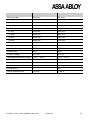
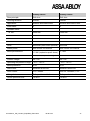
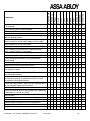
1
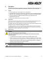
Operating Instructions Albany High-Performance Doors 6410R0231 2012 ASSA ABLOY Entrance Systems AB. All rights to the door and the related operating instructions are protected. Legal action will be taken in case of imitation or copying of the door system. These operating instructions may not be reprinted or otherwise reproduced without the written consent of ASSA ABLOY Entrance Systems. The general terms and conditions of ASSA ABLOY Entrance Systems AB are applicable. ASSA ABLOY Entrance Systems reserves the right to make technical changes. These operating instructions are an integral part of the door. The original version of the operating instructions is in German. Manufacturer ASSA ABLOY Entrance Systems AB Lodjursgatan 10 SE-261 44 Landskrona Sweden Internet: www.albanydoors.com Email: [email protected] 6410R0231_UM_Content_RapidRoll_EN04.docx 30.06.2014 2 Contents 1 1.1 1.2 1.3 1.4 1.5 1.6 1.6.1 Introduction ........................................................................................................... 5 Applicable documents ............................................................................................. 5 Declaration of conformity......................................................................................... 5 Amendments and validity ........................................................................................ 5 Document storage ................................................................................................... 5 Target group............................................................................................................ 5 Conventions ............................................................................................................ 5 Warnings ................................................................................................................. 6 1.6.2 Operation concept ................................................................................................... 6 2 2.1 2.2 2.3 2.4 2.5 2.5.1 Safety ..................................................................................................................... 7 General safety advice.............................................................................................. 7 Personal protection ................................................................................................. 7 Duty of care by the operator .................................................................................... 8 Intended use ........................................................................................................... 8 Safety devices ......................................................................................................... 9 Electric safety devices ............................................................................................. 9 2.5.2 Additional protection systems .................................................................................. 9 2.6 2.6.1 Safety devices for RR300 Plus F+R ...................................................................... 11 Radar motion detector ........................................................................................... 11 2.6.2 Belt and spring break switch ................................................................................. 11 2.6.3 Catching device with solenoid actuators ............................................................... 12 2.6.4 Regular self-tests of the door ................................................................................ 12 2.6.5 Escape route deactivation switch (optional) .......................................................... 13 2.7 3 3.1 3.2 3.2.1 Residual risks ........................................................................................................ 13 Door Product Description ................................................................................... 14 Door components .................................................................................................. 14 Operation and installation of the door systems ..................................................... 15 Safety systems ...................................................................................................... 15 3.2.2 Slats (only doors with rigid curtains) ...................................................................... 16 3.3 3.3.1 Emergency exit door Albany RR300 plus F+R ...................................................... 17 Conditions of Use .................................................................................................. 17 3.3.2 General information ............................................................................................... 17 3.4 3.5 3.6 3.7 4 4.1 Control unit ............................................................................................................ 17 Drive ...................................................................................................................... 18 Identification plate ................................................................................................. 18 Technical Data ...................................................................................................... 18 Operation ............................................................................................................. 19 Safety .................................................................................................................... 19 6410R0231_UM_Content_RapidRoll_EN04.docx 30.06.2014 3 4.2 4.3 4.3.1 Operation ............................................................................................................... 19 Malfunction ............................................................................................................ 19 Mechanical malfunctions ........................................................................................ 20 4.3.2 Electrical faults ....................................................................................................... 20 5 5.1 5.2 5.3 5.4 6 6.1 6.2 6.2.1 Installation ............................................................................................................ 21 Inspecting the delivery ........................................................................................... 21 Fitting preparations ................................................................................................ 21 Installation .............................................................................................................. 22 Dismantling ............................................................................................................ 22 Life Cycle .............................................................................................................. 23 Installation .............................................................................................................. 23 Maintenance and Cleaning .................................................................................... 23 Safety instructions.................................................................................................. 23 6.2.2 Inspection plan ....................................................................................................... 23 6.2.3 Cleaning and care .................................................................................................. 24 6.3 6.4 6.4.1 Decommissioning................................................................................................... 25 Storage and transport ............................................................................................ 25 Transport ............................................................................................................... 25 6.4.2 Storage .................................................................................................................. 26 6.5 A. A 1. A 2. A 3. B. B 1. B 2. B 3. C. D. D 1. D 2. D 2.1. Disposal ................................................................................................................. 26 Appendix .............................................................................................................. 27 Technical Data: Doors with flexible curtains .......................................................... 27 Technical Data: Doors with rigid curtains ............................................................... 32 Maximum opening and closing speeds .................................................................. 33 Appendix Inspection............................................................................................ 34 Service intervals..................................................................................................... 34 GMP-relevant inspection (only RRClean) .............................................................. 34 Inspection plan ....................................................................................................... 35 Appendix Cleaning reference RRClean ............................................................. 38 Appendix RFood .................................................................................................. 39 Notes for the application in the food industry ......................................................... 39 Cleaning reference RFood ..................................................................................... 39 Cleaning recommendations for special areas ........................................................ 41 D 2.2. Recommendation cleaning agents RFood ............................................................. 44 E. E 1. E 1.1. Appendix RR300 Plus F+R: ................................................................................. 45 Radar motion detector RR300 Plus F+R:............................................................... 45 Reference settings ................................................................................................. 45 E 2. Installation of the additional F+R components ....................................................... 45 6410R0231_UM_Content_RapidRoll_EN04.docx 30.06.2014 4 1 Introduction These operating instructions apply to the use of the following doors with associated control units: RR300, RR300PLUS, RRClean, RFood, RR200, RR355, RR392, RR450, RR500, RR600, RR3000, -R, -GL, -XXL, -ISO. They constitute part of the product and describe how to use the product properly and safely throughout the product life cycle. 1.1 Applicable documents The operating instructions are only valid in combination with the operating instructions for the control unit and the inspection book. Both of these documents are supplied with the product. A supplement to the operating instructions, which is applicable in addition to the general operating instructions, is provided for the uninterruptible power supply (UPS). 1.2 Declaration of conformity The declaration of conformity document is enclosed in the log book which is delivered with the door. Modifications that affect the technical data specified in the operating instructions or proper use, i.e. modifications that materially alter the machine, invalidate the manufacturer’s declaration of conformity. 1.3 Amendments and validity The information contained in these instructions constitutes the technical specifications applicable at time of publication. Significant changes will be incorporated in a new edition of the operating instructions. The document and version number of these instructions can be found in the footer. 1.4 Document storage Keep these operating instructions in the storage bag inside the switchbox or, for doors with an MCC control unit, in the supplied document box. 1.5 Target group These operating instructions are intended for trained, qualified and authorised staff. All configuration activities, and in particular repairs and maintenance, may only be performed by employees of the manufacturer or other trained specialists. 1.6 Conventions This section explains the conventions used in these instructions for safety information and operations. 6410R0231_UM_Content_RapidRoll_EN04.docx 30.06.2014 5 1.6.1 Warnings Warning notices give advice of existing danger for life and health of persons as well as for machine, material or environment. The advice assembled directly at the control box and the door must be noticed and kept in readable condition at all times. Warning notices in this document are formatted as follows: SIGNAL WORD Danger! Consequences Precautions If the danger is an electrical hazard, the appropriate pictogram is used: SIGNAL WORD Danger! Consequences Precautions The following warning levels are used: SIGNAL WORD Danger WARNING CAUTION Consequences of nonobservance Immediate grave danger Death or serious physical injury Potential immediate grave danger Death or serious physical injury Potential hazardous situation Minor physical injuries, material damage Hazard level This symbol leads to information explaining the various door operations. Important information 1.6.2 Operation concept Aim of the operation 1. Step → Result of the step (optional) 2. Step ... Result of the step (optional) 6410R0231_UM_Content_RapidRoll_EN04.docx 30.06.2014 6 2 Safety 2.1 General safety advice These operating instructions contain important information for commissioning, operating, transporting, storing and maintaining the door safely and properly. Please read the operating manual carefully and keep it at a safe place for further use. Take particular note of the information in this section. Also note the specific safety information included in the other sections. Use the door only for the intended purpose. Upon transfer of this door to third parties this user manual must also be transferred to this party. 2.2 Personal protection No special personal protection equipment is required for using the door. Nevertheless, the door may only be used by trained and authorised staff. Furthermore, the regulations of the plant or facility where the door is used also apply. The use of the emergency lever (if existent) may lead to a partly self-opening or closing of the door. Upon failure of the electrical drive the door leaf may be unlocked and moved upwards by use of the emergency lever. At doors with emergency hand crank, the door can be opened and closed by turning the emergency hand crank which must be inserted on the bottom of the motor. This is also possible for doors with manual hand chain. In this case the drive is switched powerless. WARNING The door may partially open or close by itself after the emergency manual lever has been activated! There is the risk of injuries by the movement of the door curtain. Observe the door during use of the emergency manual lever permanently. WARNING Risk of injury It can lead to injuries by simultaneous starting of the motor during inserting the emergency hand crank. Always switch off the main switch before using the emergency hand crank. Do not put your hands on the side columns of the door or in the area of the top roll during operation. Lingering of persons in the working area of the door should be avoided. For pedestrian traffic existing wicket doors should be used. Go upright with normal walking speed. Untidiness may cause accidents. Keep the immediate area of the door tidy. Do not climb up the door. Do not put up a ladder against the curtain. 6410R0231_UM_Content_RapidRoll_EN04.docx 30.06.2014 7 When performing any type of work on the door, set the main switch (power switch) to “Off” or “0” or disconnect the CEE plug, and secure the switch or plug against accidental re-activation or reconnection. Also observe the instructions in Section 2.5.2.4, “Uninterruptible power supply (UPS)”. Stop using the door immediately in the event of mechanical or electrical damage, especially if the power cable or control cables are damaged. The door must only be operated on defined voltage or net frequency. Use only equipment or additional features which are authorized by the manufacturer of the door. Do not operate the door when excessive wind load is present. Wind class specifications always refer to the closed position of the door. 2.3 Duty of care by the operator The door has been designed and manufactured under consideration of a risk analysis according careful selection of valid norms and further technical specifications. The system meets status of technique and ensures the highest level of safety. But this safety standard can only be reached in practice if all necessary measures and precautions are observed. It is the duty of the door operator to plan the respective measures and check it’s performance. Observe the following instructions on safe operation of the door: That installation, initial operation, inspection, maintenance, repair work and dismantling is made only by manufacturer personnel or manufacturer trained/qualified personnel. That only sufficiently trained/ qualified and authorized personnel operates the door system, Use the machine only for its intended purpose. That the machine is operated only in perfectly functioning state and that the safety features are regularly checked for orderly operation, The operation manual (in a readable condition at all times) is kept at the site of the door system for further use if necessary, That the operating personnel is continuously trained with regard to working safety and operating instructions and especially the herein containing safety instructions, The advice assembled directly at the control box and the door must be noticed and kept in readable condition at all times. 2.4 Intended use If not explicitly otherwise described, our doors are developed and tested for regular conditions. We would be pleased to advise you on the choice of suitable options for use under special conditions, such as persistent exposure on one side of the door to high or low temperature, positive or negative pressure, or other special ambient conditions. 6410R0231_UM_Content_RapidRoll_EN04.docx 30.06.2014 8 The door is defined for the closing of door openings, especially on industrial buildings which are planned mostly for vehicle traffic of various types. Exterior doors are resistant to wind and rain loads. Exterior doors can of course also be used as interior doors. For the door RFood take note of appendix D. 2.5 Safety devices 2.5.1 Electric safety devices As electrical safety system a pre-running safety photocell, electrical safety edge or a light curtain in the door line can be used, which are complemented by a door line photocell in the side frame. All electrical safety systems are designed according to the product standard EN 13241-1. Before each closing movement of the door an internal test of the safety system and the door line photocell is being performed. If a fault is detected, the closing movement is disabled and an error message is displayed by the control system. Doors in combination with MCC fulfill according to EN 13849-1 for the safety systems category 2 with performance level d and the emergency stop category 3 with performance level d. Doors in combination with ACS50 or MCS fulfill the safety systems category 2 with performance level c and the emergency stop category 1 with performance level c. With the ACS25 there is no internal test of the photocell before each down movement of the door. The photocell must be checked at least half-yearly by technical personnel. 2.5.2 Additional protection systems 2.5.2.1 Sensors Depending on the kind of door application it may be advisable to utilize additional sensors for protection reasons. This is valid for instance for applications involving a high frequency of human traffic as well as with low dimensioned doors less than 3 m in height and therefore no optical awareness given for the closing door as an additional protection. ASSA ABLOY Entrance Systems offers a big variety of further protection systems for high-speed doors. light curtain, motion sensing detectors, floor loops, etc. For individual cases we suggest consultation with an Albany Door Systems representative at the application site. At doors with a height of H ≤ 2,5m, a top roll cover is absolutely necessary. With the RR600, the top roll cover is specified as mandatory for heights less than or equal to 2.3 m. 2.5.2.2 Emergency manual lever (except RR200, RR300, RR500, RRClean and opt. RFood) At power loss, repair and maintenance work may become necessary to open the door manually: 1. By using the emergency manual lever on the side frame the brake of the drive motor can be released via a disengagement cable. 6410R0231_UM_Content_RapidRoll_EN04.docx 30.06.2014 9 → Depending on the counterweight set-up and the door position the door blade may partially open or close by itself. 2. If necessary, open the door further by manually pushing it upwards. → In the case of roll doors the door curtain will wind onto the top roll when you do this. 3. In order to reach regular function of the door again the emergency lever must be put into its original position again. 4. To use doors with ACS50 regular again, the power to the control must be turned off and on again (main switch or mains plug). For doors with MCC follow instructions on display. Once a reference search has finished the door is ready for use again. 2.5.2.3 Power on brake (Standard for RR300 Plus F+R, option for RR300 Plus) Switching off the main switch or unplugging the power cable causes automatic door motion. If the door is closed, it opens partially, and if it is open it closes partially. The RR300 Plus R+R automatically opens by at least 2 m due to the spring-driven counterbalance. It is not possible to operate the door with an emergency lever. The door is not designed for a regular manual operation. 2.5.2.4 Uninterruptible power supply (UPS) Doors with frequency converter control (only MCC) can optionally be equipped with an uninterruptible power supply (UPS). In case of a power grid failure the door can be run several times immediately after the failure. Alternativly one time up to 4 hours with the UPS in idle mode. (Precondition: the batteries have to provide the specified capacitiy) WARNING Risk of electrical shock Voltage is still present on the door after mains power has been switched off. Switch off the power switch of the UPS as well. For working inside the UPS, the internal switch must be switched off (observe the operating instructions for the UPS). 6410R0231_UM_Content_RapidRoll_EN04.docx 30.06.2014 10 WARNING Risk of personal injury and material damage Unintentional door motion can lead to damage to the product or severe personal injury. Switch off the power switch of the UPS as well. For working inside the UPS, the internal switch must be switched off (observe the operating instructions for the UPS). 2.6 Safety devices for RR300 Plus F+R 2.6.1 Radar motion detector The door has a direction-detecting radar motion detector with approval for exit and escape routes. As a result the door opens automatically if persons move towards the door in the exit direction. The exit direction is defined by the installation of the radar motion detector. If the control detects a fault in the radar motion detector the door opens automatically and remains open. It can only be put back into service after it has been repaired by a service technician. The radar sensor must be set so that it covers the full door width and at least detects persons who are 1.5 m in front of the door. Please refer to the installation instructions of the radar motion detector manufacturer for details of how to set and adjust the detector. Reference values are in a table in chapter E 1.1 . WARNING Risk of personal injury and material damage The function for exit and escape routes is not ensured, if more than one radar sensor is installed. Connection in series of additional radar sensors is not allowed. WARNING Risk of personal injury and material damage Unintentional door motion can lead to damage to the product or severe personal injury. The function of the radar motion detector is not deactivated by the Stop-button and continues to have priority. The door is opened if a person is detected by the radar sensor, regardless of whether the Stop button is pressed or not. The door must therefore be disconnected from the power supply before any maintenance and/or installation work is carried out. 2.6.2 Belt and spring break switch Proper function of the counterbalance springs and belts is monitored by switches which are located in both side frames. In faultless condition the springs, belts and switches are tensioned. 6410R0231_UM_Content_RapidRoll_EN04.docx 30.06.2014 11 If a spring or belt fails the switch is released. The door then opens electrically and switches to fault. It can only be put back into service after it has been repaired by a service technician. The switches are to be installed by means of hanging them in the S-hooks in the hooks of the springs and fixing them to the spring mounting (Chapter E 2). 2.6.3 Catching device with solenoid actuators The door has catching device which ensures an opening height of 2 m in the event of a fault occurring and simultaneous power failure. This function is provided by a solenoid actuator installed at a height of 2 m in the side frame, on the drive side. If a voltage is applied to this switch, the traverse path for the slider of the bottom profile is released; if the voltage fails the solenoid actuator locks the traverse path in the Close direction. In normal operation of the door a voltage is applied to the solenoid actuators and the traverse path for the slider is released. If a fault is detected, e.g. a spring breaks, the door is electrically moved to the top limit position and switches to fault. If a fault occurs in this situation the curtain unwinds and the bottom profile moves downwards. However, if the power supply fails, the solenoid actuator blocks the traverse path of the bottom profile and the bottom profile is stopped at the height of the solenoid actuators and an opening height of 2m remains. 2.6.4 Regular self-tests of the door To ensure the exit and escape route functions, self-tests are performed after switching on, after the escape route deactivation has ended (see Chap. 2.6.5), after 24 hours and after a power failure. 8:00 am is preset in the factory as the time for performance of the self-tests. This time can be changed to the user's needs using the display unit. When the self-tests are performed, all safety relevant electrical and mechanical functions are checked. During the performance of the self-tests the exit and escape route functions are deactivated. The electrical functions check is performed on the additional protective circuit, the control inputs, the radar motion detector and the spring and belt break switches. Further, the solenoid actuator is also actuated (see Chap. 2.6.3). The check of the mechanical functions concerns the self-opening height. This describes the achievable opening height by means of the spring mechanism, without help of the motor (e.g. in the event of a power failure). The required self-opening height is checked by releasing the brake and is 2m for use of the door in exit and escape routes. This opening height must be reached within 5s time. The self-tests are first performed with the door closed. The start of the self-test is indicated at the display. The electrical additional functions are checked within the first 10s after starting the self-test. Then the brake is released and the door is opened by the spring mechanism (self-opening). If the opening height required for use in exit and escape routes is reached within 5s, the door stops, stops briefly and then opens up to the top limit position. Following subsequent closing of the door the self-test is completed. If an error is found during the checking of the electronic or mechanical functions the door moves to the top limit position and switches to fault. This is indicated by an error message on the display. This error message can be acknowledged and the door can 6410R0231_UM_Content_RapidRoll_EN04.docx 30.06.2014 12 be released by input of a code by an authorised person. The self-tests are then repeated. If these tests are successful the door is ready for use again. The allowable time interval of 10s for performance of the tests on the electronic functions is controlled by a timer relay. This relay is located in the control housing and works with dropout (OFF) delay. CAUTION Risk of personal injury and material damage The door stays open if the self-test is not successful after repeated executions. The door must be inspected by a service technician. 2.6.5 Escape route deactivation switch (optional) If the function of the radar motion detector, the checking of the belt and spring break switches and the regular self-tests is to be suppressed (e.g. at the weekend or during company holidays), the exit and escape route functions must be deactivated by an authorised person using a key switch with the door closed. This person is responsible for ensuring that the exit and escape route functions are activated if the building is being used by people again, i.e. is occupied. A display at the operator unit of the MCC control provides information about the condition of the exit and escape route deactivation. In the event of a power failure the door opens automatically and remains in the open position, even when the power failure is corrected. The door can therefore not be viewed as being burglary or theft protection if the exit and escape route functions are deactivated. WARNING Risk of personal injury and material damage The function for exit and escape routes is not ensured, if the escape route deactivation switch is used. The door remains closed and it can then not be used either as a door or as an escape route. The exit and escape route functions must be activated if the building is being used by people again, i.e. is occupied. 2.7 Residual risks The door has been designed and manufactured under consideration of a risk analysis according careful selection of valid norms and further technical specifications. The system meets status of technique and ensures the highest level of safety. But this safety standard can only be reached in practice if all necessary measures and precautions are observed. In particular, when the door is used by people, it must be ensured that they have been instructed in the use of the door and advised of the potential danger of walking under the door while it is closing. 6410R0231_UM_Content_RapidRoll_EN04.docx 30.06.2014 13 3 Door Product Description The operation and construction of the door are described below. Consult the appropriate tables to determine the configuration options available for specific door types. 3.1 Door components The figure shows the Albany RR300 and Albany RP 2000 doors. Other types of door may differ in detail. Doors with flexible curtains Doors with rigid curtains 1 Photocell, light curtain 6 Drive system 2 Door curtain 7 Electric control box 3 top roll 8 side frame 4 Option: Top roll cover (Aluminum anodized, steel galvanized, stainless steel) 9 Continuous safeguarding, electrical safety edge, rubber profile 5 Option: Motor cover (Plastic, stainless steel, steel powder coated, aluminium) The door line photocell or light curtain (1) safeguards the closing area of the door. Disruption of the beam prevents or stops the closing movement and the direction of travel is reversed. Depending on the type, flexible door curtains (2) are made from coated, dyed and woven polyester monofilament or from transparent or coloured PVC with draught strips. Rigid curtains are made from aluminium slats. 6410R0231_UM_Content_RapidRoll_EN04.docx 30.06.2014 14 The top roll (3) has a tubular aluminium shaft with glued-in shaft stubs or a steel shaft. Doors with rigid curtains have a special DiscDrive system that prevents direct contact with the curtain surfaces during roll-up. The drive unit (6) contains an electric motor, gearbox and limit switches. The electrical switchbox (7) contains an ACS25, ACS50, MCS or MCC control unit, depending on the configuration. The side frames (8) are made from galvanised steel, aluminium or stainless steel and may also contain a counterbalance system, depending on the door model. Upon touching the safety edge (9) the door reverses into the open position immediately. A pre-running photocell may be used as an alternative. 3.2 Operation and installation of the door systems Albany doors are vertically opening high-speed roll-up doors. They consist of two side frames, a top roll with an electric drive unit, a door curtain and a bottom profile. The side frames guide the bottom profile and the door curtain, which is rolled onto the top roll when the door opens. During closing of the door the curtain rolls down from the top roll and is being pulled down by the self weight of the bottom profile and the door curtain. In the case of doors with built-in curtain tensioning, the door curtain is also actively tensioned by the force of the curtain tensioning system. Doors with a counterbalance system have this system housed in the side frames. The counterbalance assists the drive unit during door opening and also enables manual opening, for example in case of power failure, by causing the door to open partially on its own. The doors in the Albany RR450 series also have optional travelling wind bars, which can be fitted either on the front or the rear of the door as necessary. Type RR200 RR300 RR300 Plus RRClean, RR200, RR500 RFood RR355 RR392 RR450, RR600 RR3000, R, GL RR3000ISO, XXL 3.2.1 Curtain tension No No optional Counterbalance No No Springs Side frame covers screwed on None screwed on No No screwed on No Yes Yes Yes Yes No weights (optional) Springs weights Springs Springs Springs hinged screwed on screwed on hinged screwed on screwed on Safety systems All RapidRoll doors are fitted with standard-compliant protection on the main closing edge. In addition, damage to the door in the event of a collision can largely be avoided by an (optional) breakaway mechanism. 6410R0231_UM_Content_RapidRoll_EN04.docx 30.06.2014 15 The following systems are available: Breakaway Function mechanism Manual After a collision the crash system can be manually repaired. The breakaway mechanism is restored to the operating position Self-repairing by pressing a button. SRD Automatic breakaway mechanism minimises collision damage The safety systems fitted to the doors are listed in the following table. Type Securing the main closing edge Breakaway mechanism *) RR200, RR300, RR300 Plus electrical safety edge Manual RR200, RR500 electrical safety edge Self-repairing RRClean electrical safety edge or optional pre-running photocell None RFood electrical safety edge or optional pre-running photocell Manual RR355 pre-running photocell or optional electrical safety edge Self-repairing RR392 electrical safety edge Manual RR450 pre-running photocell or optional electrical safety edge Self-repairing RR600 pre-running photocell or optional electrical safety edge RR3000, R, GL, -XXL pre-running photocell or optional electrical safety edge None RR3000 ISO Light curtain up to 2,5m height None SRD or Self-repairing * The type of breakaway mechanism depends on the type of bottom edge protection All doors also have a door line photocell system integrated in the side frames. Disruption of the door line photocell or triggering the safety edge leads to a complete stop of the door curtain. After the door curtain stops it will reverse to the open position. 3.2.2 Slats (only doors with rigid curtains) The slats are individually suspended, double-walled extrusions sealed relative to each other. Type Slats Window(s) * RR3000, -R, -XXL Double-wall anodised optional RR3000 GL Window frames anodised with single glazing Full RR3000 ISO foamed sandwich-panel with steel sheets RAL 9006 optional * The number depends on the door size and type, among other things 6410R0231_UM_Content_RapidRoll_EN04.docx 30.06.2014 16 3.3 Emergency exit door Albany RR300 plus F+R 3.3.1 Conditions of Use These instructions are directed at the owner/operator of the Albany RR300 Plus F+R emergency exit door. The owner/operator is responsible for correct use, instructing the operating personnel and for technical maintenance of the door. These instructions for the basis for intended use and faultless functioning of the door. The Albany RR300 Plus F+R has been built to state of the art standards and the recognised safety guidelines for exit and escape routes and has been approved by an independent test body. Any change whatsoever to the door results in withdrawal of the operating permit as an emergency exit door; the manufacturer's liability is cancelled by any failure to observe this requirement or in case of deliberate misuse. The door system may be disconnected from the mains in emergencies only. Disconnecting it over night is not allowed! 3.3.2 General information The Albany RR300 Plus F+R conforms to the essential requirements of the “Richtlinie über automatische Schiebetüren in Rettungswegen” (AutSchR Guidelines for Automatic Sliding Doors in Escape Routes). The consent of the responsible building authority must always be obtained for approval for use of the door in exit and escape routes. The door has an automatic opening function to make it suitable for use in exit and escape routes. This ensures opening of the door as soon as persons move towards the door in the exit direction. The door has various monitoring and control devices to ensure the exit function even in the event of a power failure or damage (spring wear, spring break, belt break). The exit and escape route function exists if the opening height is at least 2m. The door is delivered with a display on which information for operation and about the status of the door is displayed. It is therefore recommended that this display be installed in the immediate vicinity of the door, if the display is not planned to be mounted on the side frame. 3.4 Control unit Albany doors may be operated with a powerful frequency converter control unit MCC respectively MCS-FC, which enables soft acceleration and deceleration of the door. Alternatively, several types of doors can be operated with a contactor control unit ACS50 respectively MCS-R. See the table in the appendix (Section A 3) for the maximum closing speeds of the individual door types. DANGER! Risk of electrical shock Operating doors with drive units or control units other than the recommended types may create a risk of electrical shock. The door must only be operated with an original drive and control unit from the manufacturer. 6410R0231_UM_Content_RapidRoll_EN04.docx 30.06.2014 17 3.5 Drive The high-speed doors are operated by electrical drives. The drive unit is installed at the upper part of the door, vibration muffled and not accessible from the floor. The position of the drive unit may be selected by the customer for the right or left hand side. The temperature of the drive unit is safeguarded by a thermo element, which disrupts the power supply of the drive upon overheating. In the case of doors without counterbalance, the gearbox is equipped with a catching device. 3.6 Identification plate (the actual data will vary depending on the specific door) 3.7 Technical Data The inspection book contains the following technical data: Technical Data Door dimensions Dimensions of the installed door Fitting clearances Fixing points Location Principle drawing Fixing plan See the appendix (Sections A 1 and A 2) for all other technical data for the door. ASSA ABLOY Entrance Systems reserves the right to make changes to technical information listed in this document. 6410R0231_UM_Content_RapidRoll_EN04.docx 30.06.2014 18 4 Operation This section describes the operation of the door, irrespective of the control unit used. See the control unit user manual for a description of the control unit concerned. 4.1 Safety Do not use this door for purposes it is not intended for. Upon damage of the door (mechanical or electrical) it must immediately be set off operation. This is especially valid on damages of the power net or control cables. Use only equipment or additional features which are authorized by the manufacturer of the door. Observe the safety instructions in Section 2 also. 4.2 Operation The door has an electrical drive unit and can be operated using the buttons on the door control unit or by additional external actuators and safety devices. The Open, Stop and Close buttons on the door control unit should normally be used during door setup, maintenance and repair activities. In regular operation, the door is controlled by external signal sources such as pullcord switches, induction loops, radar or radio detectors or mushroom-head buttons connected to the door control unit via dry contacts. 4.3 Malfunction DANGER Risk of personal injury and material damage Improper troubleshooting can lead to damage to the product and serious personal injuries. Troubleshooting must always be performed by suitably qualified staff. Switch off power to the door and secure it against accidental re-activation. Also observe the instructions in Section 2.5.2.4, “Uninterruptible power supply (UPS)”. Secure the main switch or CEE connector against being switched on again by locking it or by having a second person present. Secure the action area of the door. If the error cannot be repaired please contact the after market department of the supplier or manufacturer of the door. 6410R0231_UM_Content_RapidRoll_EN04.docx 30.06.2014 19 4.3.1 Mechanical malfunctions Malfunction Door opens independently Manual opening not possible Drive without any function curtain unwraps inclined 4.3.2 Possible causes Necessary measures Brake at the drive defect Exchange the brake Brake wrongly adjusted Adjust the brake Counter-balance is oversized Call after market Counter-balance defective Exchange the counter-balance devices Bowden cable hanging off or too loose Check correct position and tension of the bowden cable Brake blocking Call after market Power supply is off Connect the door to the power Electrical connections defective Check electrical connections Fuse has blown Replace fuse Door not correctly installed Call after market An object was rolled up Close the door and check for enclosed object Electrical faults Malfunction Door without any function Door does not close Door close only with next impulse Possible causes Necessary measures Power supply is off Check power supply, net fuse Control system fuse blown Check control unit and exchange the fuse Main switch off Check (main switch) switch on Stop-circuit interrupted Check stop circuit. Not used stop inputs must be bridged in accordance to the circuit diagram Up impulse permanently activated Test impulse actuator Photocell interrupted / disconnected Test safety devices Toggle circuit adjusted Check adjusted control function 6410R0231_UM_Content_RapidRoll_EN04.docx 30.06.2014 20 5 Installation DANGER Risk of injury Improper handling of the packaged door can lead to injury. The palette must be placed on even ground. Do not remove the pallet before the start of installation. 5.1 Inspecting the delivery The door is mainly preassembled when delivered. The side columns are fixed together with the barrel cover, the motor cover (if ordered), fixing material and control unit onto the transport device (wooden palette). Check the door for damage during transport. Check the delivered items against the order documents to ensure that the delivery is complete. 5.2 Fitting preparations DANGER Risk of injury Incorrect installation of the door can lead to injury. The door must only be installed by trained/authorized personnel. The fitting should only be done by manufacturer personnel/subcontractor or manufacturer trained personnel. Do not remove the straps securing the door curtain until after the drive unit has been fitted. Complete the following preparations before installing the door: Check the fitting site with regard to necessary fixing points and lift up conditions. If necessary a supporting frame or other fixing possibilities must be made. The upper fixing points should be screwed onto a steel supporting frame or concrete element. Consult the installation drawing in the inspection book. Check measures of the actual dimensions (width and height) of the door opening and compare with order papers. The fitting site must be secured against pedestrian and vehicle traffic. The plastic packing of the door must be removed before fitting. For the door RFood take note of chapter D. 6410R0231_UM_Content_RapidRoll_EN04.docx 30.06.2014 21 DANGER! Risk of injury Unsecured guiding cover can fall down for door types RR3000. By pushing up and unhook the bottom guiding cover the upper side cover can be unmounted. The door must only be installed by trained/authorized personnel. The fitting should only be done by manufacturer personnel/subcontractor or manufacturer trained personnel. The upper side cover must be mounted when removing the bottom guiding cover. 5.3 Installation The fitting team has a detailed installation manual. In case of questions, contact ASSA ABLOY Entrance Systems. The door must be connected to the potential equalisation rail (min. 6 mm²). Therefore is an earthing screw in the area of the drive unit or in the lower part of the side frame on the drive side which is marked with an earth symbol. 5.4 Dismantling To dismantle the door, follow the installation instructions in reverse order. 6410R0231_UM_Content_RapidRoll_EN04.docx 30.06.2014 22 6 Life Cycle 6.1 Installation See the user guide for the associated control unit. 6.2 Maintenance and Cleaning In case of necessary work of maintenance, malfunction, repair, please ask your supplier or manufacturer of the door. ASSA ABLOY Entrance Systems Albany Door Systems GmbH Service Department Am Mondschein 25 59557 Lippstadt, Germany Tel.: +49 (0)2941 766 0 Fax: +49 (0)2941 766 294 Internet: www.albanydoors.com Email: [email protected] 6.2.1 Safety instructions The maintenance and inspection work must only be performed by manufacturer trained/ authorized personnel. Before performing any maintenance and cleaning work, disconnect the door from the mains by switching off the lockable main switch on the switch box or unplugging the CEE connector. Also observe the instructions in Section 2.5.2.4, “Uninterruptible power supply (UPS)” Use a meter or other test device, verify that the switch box is de-energised. Please observe that all used ladders, scaffoldings, or such, correspond with the valid safety regulations. The working area must be blocked for traffic. Lubricating oil on the floor, tools and other material should be removed from the floor when work has been finished. 6.2.2 Inspection plan Record all maintenance, repairs and modifications in the inspection list included in the inspection book for every door, to ensure that all changes can be traced. The necessary service events, inspections and implementation notes are documented in the inspection plan in chapter B. WARNING Risk of personal injury and material damage RR300 Plus F+R: The function for exit and escape routes is not ensured, if maintenance plan is not followed. Compliance with the inspection plan is necessary in order to maintain the exit and escape routes characteristics. Special points of the inspection plan for the RR300 Plus F+R have priority. 6410R0231_UM_Content_RapidRoll_EN04.docx 30.06.2014 23 DANGER Risk of explosion RR450Ex / 600Ex: Improper maintenance nullifies the Declaration of Conformity with regard to the ATEX directive. Compliance with the inspection plan is necessary in order to maintain the explosion protection characteristics. Maintenance activities and extended downtime periods (if any) should be planned in. 6.2.3 Cleaning and care 6.2.3.1 Door curtain Pay particular attention to the cleaning instructions in the appendix for the RRClean (C) and RFood (D 2) doors. CAUTION Risk of material damage Improper cleaning of the curtain may cause damage to the surface. Do not use any glass cleansing liquids (aggressive contents) Never use score cleansers, scrapers, razor blades and spatula, etc. Clean with warm water, small dose of mild plastic cleanser and a soft non-bobble cloth. DANGER Risk of personal injury and material damage Pollution of the curtain can cause reduction (loss) of the protection property for laser protection doors. The surface facing to the laser must be kept clean. 6.2.3.2 Side Frames CAUTION Risk of material damage Improper cleaning of the door frame may cause damage to the surface. Do not use high pressure cleaning machine. Dust may be removed with a soft cloth. Harder dirt may be removed with water and general liquid cleanser. Dirt of grease or oil on metal surface may be removed with solvent containing cleanser. 6410R0231_UM_Content_RapidRoll_EN04.docx 30.06.2014 24 6.2.3.3 Surroundings Especially after maintenance work the floor around the side columns may be dirty with lubricants, etc. Carefully clean these areas. 6.3 Decommissioning Follow the installation instructions for dismantling. Disconnect power from the door before dismantling. In particular, ensure that all springs are de-tensioned. Also observe the instructions in Section 2.5.2.4, “Uninterruptible power supply (UPS)” Check parts that are subject to wear and replace them if necessary before reassembly. Check all connectors and avoid kinking cables. Store all components in a clean, dry place. 6.4 Storage and transport 6.4.1 Transport The single door components must only be removed from the packaging at the site of installation. DANGER Risk of injury Improper transport may cause the load to slip and fall. Observe the legal safety regulations when transporting the door to the fitting site.The door must be secured against tilting or slipping. Lift the door at its centre of gravity to prevent it from tipping sideways. 6410R0231_UM_Content_RapidRoll_EN04.docx 30.06.2014 25 6.4.1.1 Dimensions of the door with packaging Transport pallet [mm] Drive and control unit pallet [mm x mm] Door Length Length x width RR200 W + 1000 530 800 x 600 RR300, RR300 Plus, RRClean H + 500 500 800 x 600 RR355, RFood H + 500 650 800 x 600 RR392 H + 800 750 800 x 600 RR450, RR600 H + 800 750 800 x 600 RR500 W + 1000 750 800 x 600 RR3000, R, GL; pallet 1 (top roll) W + 850 750 RR3000 XXL, ISO (H<4700); pallet 1 (top roll) W + 850 850 RR3000 ISO (H>4700); pallet 1 (top roll) W + 850 980 RR3000, R, GL, ISO, XXL pallet 2 (side frames) H + 600 750 Width W = width of door opening; H = height of door opening 6.4.1.2 Weight of the door with pallet [Kg±10%] 6.4.2 920 780 620 870 250 325 270 340 RR3000 ISO, XXL side frame 330 420 500 RR3000 ISO, XXL top roll 270 380 500 RR3000 R side frame RR3000, GL side frame 480 610 740 RR3000 R top roll RR3000, GL top roll 400 370 530 445 650 535 RR450 400 470 630 770 RR392 RR355 RR600 6x6 175 215 260 330 400 RR500 5x5 140 175 210 270 RR300 Plus, RFood WXH [m] 116 2x2 2 x 2,5 149 3x3 184 4x4 RR300, RRClean RR200 (Intermediate values can be interpolated; weights may vary depending on specific configuration options.) 430 580 520 630 750 770 250 300 380 Storage The partly preassembled door is being delivered on a transport resp. mounting palette completely wrapped with plastic material. Undamaged packing allows storage of the door outside of buildings for several days. 6.5 Disposal The packing material of the door may be returned to the manufacturer. Defect door components should be disposed of at the site according environmental regulations. Defect electronic components should be disposed to special waste disposal. 6410R0231_UM_Content_RapidRoll_EN04.docx 30.06.2014 26 A. Appendix The following tables list technical data for the doors. A capsule summary of the maximum opening and closing speeds is also provided in Section A 3. A 1. Technical Data: Doors with flexible curtains Albany RR300 Albany RR300 Plus Door principle: Roll door Roll door Running direction: vertical vertical Application: Interior door Interior door Wind class: 1 1 W min: 500 mm 1000 mm W max: 4000 mm 5000 mm H min: 500 mm 1000 mm H max: 4200 mm 5000 mm Drive: electrical electrical Mains power: See control unit manual See control unit manual Motor performance: 0,37 kW; 0,56 kW; 0,75 kW 0,75 kW Control unit: MCC, ACS50 (50 Hz only), ACS25 (50 Hz only) MCC, ACS50 (50 Hz only, W max. 4000 mm, H max. 4200 mm) Control voltage: 24 V DC 24 V DC Operating temperature range: +10°C - +40°C +10°C - +40°C Motor protection: IP55; IP54 with ACS25 IP55 Side frame: Galvanised steel or stainless steel Aluminum or stainless steel Door curtain: PVC, Rolltex, Nomatex, Travitop PVC, Rolltex, Nomatex, Travitop Available sizes: Lifting device: Sound pressure level: Pulley, cable and belt 70 dB A 6410R0231_UM_Content_RapidRoll_EN04.docx 70 dB A 30.06.2014 27 Albany RRClean Albany RFood Door principle: Roll door Roll door Running direction: vertical vertical Application: Interior door Interior door Wind class: 0 1 W min: 1000 mm 1000 mm W max: 3500 mm 4000 mm H min: 1000 mm 1000 mm H max: 3500 mm 4000 mm Available sizes: H max (ACS50): 3500 mm Drive: electrical electrical Mains power: See control unit manual See control unit manual Motor performance: 0,75 kW 0,75 kW Control unit: MCC, ACS50 (50 Hz only) MCC, ACS50 (50 Hz only) Control voltage: 24 V DC 24 V DC Operating temperature range: +10°C - +40°C 0°C - +40°C Motor protection: IP55 IP55 Side frame: Galvanised steel or stainless steel stainless steel Door curtain: PVC PVC, Travitop Lifting device: Sound pressure level: Pulley and cable 70 dB A 6410R0231_UM_Content_RapidRoll_EN04.docx 70 dB A 30.06.2014 28 Albany RR200 Albany RR500 Door principle: Roll door Roll door Running direction: vertical vertical Application: Interior door Exterior and interior door Wind class: 1 3 (4 if DW<6000) W min: 1000 mm 1500 mm W max: 4000 mm 8000 mm H min: 1000 mm 2200 mm H max: 4000 mm 5500 mm Drive: electrical electrical Mains power: See control unit manual See control unit manual Motor performance: 0,75 kW 0,75 kW Control unit: MCS MCS Control voltage: 24 V DC 24 V DC Operating temperature range: +10°C - +40°C +10°C - +40°C Motor protection: IP54 IP54 Side frame: anodized aluminum anodized aluminum Door curtain: PVC Rolltex plus Available sizes: Lifting device: Sound pressure level: belt 70 dB A 6410R0231_UM_Content_RapidRoll_EN04.docx 70 dB A 30.06.2014 29 Albany RR355 Albany RR392 Door principle: Roll door Roll door Running direction: vertical vertical Application: Exterior and interior door Exterior and interior door Wind class: 2 2 W min: 1000 mm 2000 mm W max: 4000 mm 6000 mm H min: 1500 mm 2000 mm H max: 4200 mm 6000 mm Drive: Electrical (chain drive optional) Electrical (chain drive optional) Mains power: See control unit manual See control unit manual Motor performance: 1,1 kW 1,1 kW Control unit: MCC, ACS50 (50 Hz only) MCC, ACS50 (50 Hz only) Control voltage: 24 V DC 24 V DC Operating temperature range: -10°C - +40°C -10°C - +40°C Motor protection: IP55 IP55 Side frame: anodized aluminum galvanized steel Door curtain: PVC, Rolltex PVC, Rolltex Lifting device: Pulley and cable Pulley and cable Sound pressure level: 70 dB A 70 dB A Available sizes: 6410R0231_UM_Content_RapidRoll_EN04.docx 30.06.2014 30 Albany RR450 Albany RR600 Door principle: Roll door Roll door Running direction: vertical vertical Application: Exterior and interior door Exterior and interior door Wind class: 2 3 W min: 2000 mm 1500 mm W max: 7500 mm 6000 mm H min: 2000 mm 2000 mm H max: 6000 mm 6000 mm Drive: Electrical (chain drive optional) electrical Mains power: See control unit manual See control unit manual Motor performance: 1,1 kW 1.5 kW (explosion-proof doors) 1,1 kW Control unit: MCC, ACS50 (50 Hz only) MCC Control voltage: 24 V DC 24 V DC Operating temperature range: -10°C - +40°C -10°C - +40°C Motor protection: IP55 IP55 Side frame: anodized aluminum anodized aluminum Door curtain: PVC, Rolltex RollTex, Nomatex, PVC Lifting device: Pulley, cable and belt Pulley and steel cable Sound pressure level: 70 dB A 70 dB A Available sizes: 6410R0231_UM_Content_RapidRoll_EN04.docx 30.06.2014 31 A 2. Technical Data: Doors with rigid curtains Albany RR 3000 Door principle: Roll door Running direction: vertical Application: Exterior and interior door Wind class: 3 U-value: - 3000 GL 3 - 3000 R 3 3000 ISO 3000 XXL 2–4 2 2 - 1,5 W/m K Available sizes: W min: 600 mm W max: 5000 mm 5000 mm 6000 mm 7000 mm 8000 mm H min: 3125 mm 2500 mm 1500 mm 2500 mm 2500 mm H max: (height increment 125 mm) 5000 mm 5000 mm 3000 mm 6000 mm (height increment 100 mm) 6000 mm Drive: electrical Mains power: See control unit manual Motor performance: 1,1 kW Control unit: MCC Control voltage: 24 V DC Operating temperature range: -10°C - +40°C Motor protection: IP55 Side frame: galvanized steel Door curtain: Anodized aluminum slats, some with windows RR3000 ISO: Foamed sandwich-panel with steel sheets RAL 9006, Optional with double-glazed windows Lifting device: Sound pressure level: Flat belt with reinforcing steel ropes, belt 70 dB A 6410R0231_UM_Content_RapidRoll_EN04.docx 30.06.2014 32 Maximum opening and closing speeds RR200 2.0 RR300 2.0 1.0 1.0 0.8 RR300 Plus 2.2 0.9 1.2 1.2 RRClean 2.0 1.0 1.0 1.0 RFood 2.2 1.0 1.0 1.0 RR392 2.2 0.9 0.8 0.8 RR450 2.2 0.9 0.8 0.8 RR500 2,0 or 3,2*) 1.2 RR3000 2.2 0.7 RR3000 R 2.0 0.6 RR3000 ISO 2,1 0,7 RR3000 GL 1.8 0.7 RR3000 XXL 1.8 0.6 Close Open 0.6 0.8 0,8 RR600 ACS25 Close MCS Open Open Open m/s (max) ACS50 Close MCC Close A 3. 0.8 0,4 * Depending on door size 6410R0231_UM_Content_RapidRoll_EN04.docx 30.06.2014 33 B. Appendix Inspection The following tables list inspection plans for the doors. The overview of the service intervals are provided in section B 1. The numbers are used in the inspection plan 0. Information for RRClean doors for GMP-relevant aspects are provided in section B 2. B 1. Service intervals 1 2 3 4 5 6 7 8 9 10 11 12 13 14 15 16 ** half-yearly or 50.000 cycles (* only for RR300 Plus F+R) annually or 50.000 cycles annually or 100.000 cycles annually clean if necessary every 4 years 150.000 cycles 250.000 cycles 500.000 cycles 150.000 cycles; RR300 Plus F+R: 100.000 cycles with MCC: 150.000 cycles; with ACS50: 50.000 cycles RR450Ex / 600Ex: 200.000 cycles 150.000 cycles; RR450Ex/600Ex 50.000 cycles 200.000 cycles; RR600 Crash: 100.000 cycles DH < 3m: 500.000 cycles; DH ≥ 3m: 250.000 cycles DH < 4m: 300.000 cycles; DH ≥ 4m: 200.000 cycles Exchange of bearings only by drive manufacturer or an approved workshop for the maintenance of the explosion-proofness. (downtime at the time of external execution of the exchange, which can be expected, approx. 8-10 working days) *** Regular conditions: central European climate, door mounted interior or exterior with covers, no aggressive ambient conditions ≤150.000 cycles: ±10.000 cycles; >150.000 cycles: ±20.000 cycles B 2. GMP-relevant inspection (only RRClean) Could be done also by the customer. Mechanical components proposal Check air leakage: Curtain should permit only small air leakage around gaps 3 months or 25000 cycles Motor sealing: Motor cover should fit firm and tight, cable glands must be orderly 3 months or 25000 cycles 6410R0231_UM_Content_RapidRoll_EN04.docx 30.06.2014 34 RR300 Plus RRClean RFood RR355 RR392 RR450 RR500 RR600 RR3000, R, GL RR3000 XXL RR3000 ISO Inspection plan RR300,RR200 B 3. Installation fixings Tighten screws Check welding seams 1 1 1 1 2 2 1 1 1 1 1 1 1 1 1 1 1 1 3 3 2 2 3 3 Drive Check the fixing of the torque arm and buffer 1 1 2 1 1 1 1 1 1 3 2 3 1 1 2 1 1 1 1 1 1 3 2 3 1 1 1 1 1 3 2 3 1 1 1 3 2 2 3 2 3 3 2 3 3 2 2 3 2 2 3 2 2 3 2 2 3 3 2 2 3 2 Inspection Check brake condition and function of break release lever Check operation smoothness and function of the emergency manual lever, maybe lubricate Check the chain, adjust and possibly retension and lubricate 1 RR450Ex / 600Ex: Change bearings in motor**: 1 6 Drive shaft Check screws to drive shafts and flange bearings 1 1 2 1 1 1 Lubricate pedestal bearing and retighten it’s fixation Check the drive shaft in the aluminium shaft for secure fit Check tight position of belt and rope discs Check the condition of the cable drums Check retainer of spiral disk on the shaft Chain drive: check fastening of locking element, tighten the screws with 18 Nm Check condition of sound isolation profiles at the spiral disks Check flat belts for wear and damage; check connection to spiral disks 1 1 1 1 2 1 1 1 1 1 1 1 1 1 1 1 Door curtain Check curtain for cracks and traces of scrapes or 1 shavings in the guides Check fixation of door leaf at the top roll and at the 1 bottom profile Check tight position and wear & tear of the wind tabs 1 Bead/belt: condition, lubrication, wear; if necessary replace teeth Check exact position of slat sealing Check fixing of slats on pulling device and endcaps 6410R0231_UM_Content_RapidRoll_EN04.docx 1 1 30.06.2014 1 2 1 1 1 1 1 1 1 2 1 1 1 1 1 1 1 2 1 1 1 1 1 1 1 35 RR3000, R, GL RR3000 XXL RR3000 ISO RR300 Plus Bottom profile Check tight fit and condition of profile, guiding pieces 1 and the gliding pieces 1 2 1 1 1 1 1 1 2 1 1 1 1 Check condition of the coily cable 1 Check the condition and function of the crash system 1 Check condition and function of wireless safety 7 edge; change battery if necessary 1 1 1 1 1 1 1 Check condition of the safety edge and the cable side frame Check fixing and condition of the profiles with attachments Check cable laying and if applicable cable chain Remove dirt from the photocell optics Check condition, fixing and lengthwise extension of the ropes and belts Check the condition and function of the counterweight system Check condition and installation of the springs and the spring mounting, if applicable check for easy movement of the axial bearing Doors with ripped belt / rope or broken springs are to be immediately taken out of service 1 1 1 1 1 1 1 2 1 1 1 1 1 1 3 2 3 1 5 1 5 2 5 1 5 1 5 1 5 1 5 1 5 1 5 3 5 2 5 3 5 1 1 1 1 1 1 1 3 2 2 1 1 1 1 1 1 1 3 2 2 3 2 3 1 Yes 1 Check for wear & tear (s) on guiding rails, especially in the area of funnel (s< 4mm) 6410R0231_UM_Content_RapidRoll_EN04.docx 1 7 Check leaf tensioning system Renew belt/s Renew spring/s Renew ropes Renew ropes and pulleys for counterbalance Renew ropes or rubber cable for curtain tension Renew flat belt*** RR600 3 RR500 2 RR450 3 RR392 Check solid position of slat adapter RR355 2 RFood 2 RRClean 3 RR300,RR200 Check slats around adapters for damage (especially 1-5 from top) Inspection 1 1 1 Yes Yes Yes Yes Yes Yes 1 1 1 1 8 10 10 30.06.2014 8 7 15 16 16 9 13 9 15 16 16 11 7 8 11 12 14 8 8 9 9 9 9 36 RR300,RR200 RR300 Plus RRClean RFood RR355 RR392 RR450 RR500 RR600 RR3000, R, GL RR3000 XXL RR3000 ISO 4 4 4 4 4 4 4 4 4 4 4 4 4 4 4 4 4 4 4 4 4 4 4 4 Check the fixing 4 4 4 4 4 4 4 4 4 4 4 4 Electrical components Visual inspection for mechanical damage Check potential balance 1 4 1 4 2 4 1 4 1 4 1 4 1 4 1 4 1 4 3 4 2 4 2 4 Inspection Control box and additional attachments (e.g. impulse activator) Check for full number/completeness of circuit diagrams Check main switch/CEE-plug and control box lock Safety equipment and impulse activators Measure self-opening height after switching off the door and document in the inspection logbook (minimum self-opening height: 2m) Check self-test function by switching the key switch or switching the door On/Off Function Check function of safety edge, photocell, additional safeties and actuators Check function and condition of the torque arm during operation Assess possibility of emergency opening Check opening and closing position of the bottom profile Check winding performance of door curtain and ropes/belts Check function of belt and spring break switch Check function of magnetic switch at 2m door height Check radar motion detectors for mechanical damage and that they function properly (required detection range: whole door width, up to 1.5m in front of the door) Check main closing edge according to EN 13241-1 respectively local standards 6410R0231_UM_Content_RapidRoll_EN04.docx 1* 1* 1 1 1 1 1 1 1 1 1 1 1 1 1 1 2 1 1 1 1 1 1 3 2 2 1 1 2 1 1 1 1 1 1 3 2 2 1 1 2 1 1 1 1 1 1 3 2 2 1 1 2 1 1 1 1 1 1 3 2 2 4 4 4 4 4 4 4 4 4 4 1* 1* 1* 4 30.06.2014 4 37 C. Appendix Cleaning reference RRClean The door could be cleaned with commercially available cleaning agents and disinfectant for clean room applications. CAUTION Risk of material damage Improper cleaning of the door may cause corrosion and discoloration of the surface. Do not use chlorous cleaning agents and disinfectant. CAUTION Risk of injury Door movements during cleaning could cause injuries. Set the main switch (power switch) to “Off” or “0” or disconnect the CEE plug, and secure the switch or plug against accidental re-activation or reconnection. The maintenance, inspection work and basic cleaning must only be performed by manufacturer trained/ authorized personnel. Always follow the safety instructions mentioned in the user manual. Maintenance cleaning Clean outer surfaces with cleaning agent and disinfectant Basic cleaning (during inspection) Open side frames and clean side frame guides and trailing chain for cable Clean lintel profile Open top roll and motor cover and clean this area Mount everything in reverse order Periods need to be adjusted according to the cleaning concept and production relevance. 6410R0231_UM_Content_RapidRoll_EN04.docx 30.06.2014 38 D. Appendix RFood Special notes for the RFood are summarised in this annex. D 1. Notes for the application in the food industry The following notes are applicable to the installation and operation of RFood in food processing plants. A good cleanability and integration according the hygiene examination (DGUV 11206) in the operational HACCP (Hazard Analysis and Critical Control Points) concept is possible when observing the following points. An evaluation and consideration for the respective operational requirements must be done individually. Door application only as interior door. The rooms are according EU regulation 852/2004 appendix II/ Install the control box and additional parts (e.g. actuators) with a tilt angle of 3°. The distance of the control box should be min. 50 mm (2"). Cables are fed into the control box from below through cable glands. Use open cable duct of stainless steel for wiring outside of the door. Observe the cleanability behind cable ducts and at fixing points. Install the door on the warm side when there are different temperature levels. Thereby the condensation is prevented or reduced. Only packaged food or food in covered containers should be moved through the door. Use hexagon head screws for fixing the door, the control box and additional parts. Seal the door to the wall. Horizontal sealings need a radius of min. 3 mm or a downgrade. The used additional materials (screws, cables, cable ducts, sealing compound, etc.) must be suitable for the condition of use. The door should be equipped the easy accessible side covers and a motor and top roll cover. D 2. Cleaning reference RFood CAUTION Risk of material damage Improper cleaning of the door may cause corrosion and discoloration of the surface. Do not use chlorous cleaning agents and disinfectant. The maintenance and inspection work must only be performed by manufacturer trained/ authorized personnel. Daily routine and basic cleaning must only be performed by briefed personnel. Always follow the safety instructions mentioned in the user manual. 6410R0231_UM_Content_RapidRoll_EN04.docx 30.06.2014 39 CAUTION Risk of personal injury and material damage Door movements during cleaning could cause injuries or material damage. Set the main switch (power switch) to “Off” or “0” or disconnect the CEE plug, and secure the switch or plug against accidental re-activation or reconnection. The door can be treated with commercial cleaners and disinfectants for the foodstuffs industry. Recommendations for cleaning agents are listed in D 2.2. Surface cleaning 1. Close the door completely 2. Clean outer surfaces with cleaning agent and disinfectant Daily routine maintenance cleaning 1. Close the door completely 2. Clean outer surfaces with cleaning agent and disinfectant 3. Clean side frames (chapter D 2.1.2) 4. Clean top roll cover (chapter D 2.1.3) 5. Clean rope for counterweight system (chapter D 2.1.4) 6. Carry out test run Basic cleaning Open the motor cover and clean this area for the basic cleaning additionally to the above listed work (chapter D 2.1.5) The pollution of the door by cleaning the environment should be avoided. The order of the cleaning steps and the art of cleaning can avoid that a purified door is contaminated again by cleaning the periphery. If the door is again contaminated by cleaning the periphery, it must be once again be cleaned in the appropriate places (inside). Periods need to be adjusted according to the cleaning respectively HACCP concept and production relevance. 6410R0231_UM_Content_RapidRoll_EN04.docx 30.06.2014 40 D 2.1. Cleaning recommendations for special areas D 2.1.1. Cleaing control cabinet It may get no splash water in the control cabinet. Do not use a water hose or pressure washer. Even when main switch is turned off components within the control cabinet can be electrically live! 1. Set the main switch (power switch) to “Off” or “0” or disconnect the CEE plug, and secure the switch or plug against accidental re-activation or reconnection. 2. Open the control cabinet door to clean the drainage channel on the control cabinet and the rubber seal in the control panel door. 3. Clean with a clean, damp cloth. 4. Immediately close to the control cabinet door after cleaning. D 2.1.2. Cleaning side frame 1. Open the door up to a height of about 1m. 2. Set the main switch (power switch) to “Off” or “0” or disconnect the CEE plug, and secure the switch or plug against accidental re-activation or reconnection. CAUTION Risk of personal injury and material damage Door movements during cleaning could cause injuries or material damage. Set the main switch (power switch) to “Off” or “0” or disconnect the CEE plug, and secure the switch or plug against accidental re-activation or reconnection. 3. Open side frame: Loosen the lock screw which is located in about 1m height at the front of the side frame (1 turn). Move the lock screw a few mm to the side. Pull the locking lever and push upwards. Then swing open the side frame cover. Use a water hose for cleaning. Do not use high pressure cleaning machine. 4. Check cleanliness of side frames, especially of the cable chain and clean if required. A clean, soft brush with plastic bristles can be used to support the cleaning. 5. After cleaning you need to check whether all links of the cable chain are engaged. 6. Close the side frame covers and secure with the lock screw. 7. Switch on main power. 8. Carry out test run. 6410R0231_UM_Content_RapidRoll_EN04.docx 30.06.2014 41 D 2.1.3. Cleaning inside top roll cover 1. Open the door up to a height of about 1m. 2. Set the main switch (power switch) to “Off” or “0” or disconnect the CEE plug, and secure the switch or plug against accidental re-activation or reconnection. CAUTION Risk of personal injury and material damage Door movements during cleaning could cause injuries or material damage. Set the main switch (power switch) to “Off” or “0” or disconnect the CEE plug, and secure the switch or plug against accidental re-activation or reconnection. 3. Open top roll cover: Loosen both screws at the front side of the top roll cover. Do not remove the screws from the top roll cover. Pull the top roll cover forward. This swings the top roll cover forward and upward and remains open in the topmost position. Use a water hose for cleaning. Do not use high pressure cleaning machine. 4. Check cleanliness inside the top roll cover and clean if required. 5. Check cleanliness of the cable channel, which connects the side frames, and the gap between cable channel and wall and clean if required. A clean, soft brush with plastic bristles can be used to support the cleaning. 6. Close the top roll cover and secure with the lock screw. 7. Switch on main power. 8. Carry out test run. D 2.1.4. Cleaning the rope for the counterweight system (option) 1. Open the door completely. 2. Set the main switch (power switch) to “Off” or “0” or disconnect the CEE plug, and secure the switch or plug against accidental re-activation or reconnection. CAUTION Risk of personal injury and material damage Door movements during cleaning could cause injuries or material damage. Set the main switch (power switch) to “Off” or “0” or disconnect the CEE plug, and secure the switch or plug against accidental re-activation or reconnection. 3. Open side frame: Loosen the lock screw which is located in about 1m height at the front of the side frame (1 turn). Move the lock screw a few mm to the side. Pull the locking lever and push upwards. Then swing open the side frame cover. 4. Open top roll cover: Loosen both screws at the front side of the top roll cover. Do not remove the screws from the top roll cover. Pull the top roll cover forward. This swings the top roll cover forward and upward and remains open in the topmost position. 6410R0231_UM_Content_RapidRoll_EN04.docx 30.06.2014 42 Use a water hose for cleaning. Do not use high pressure cleaning machine. 5. Check cleanliness of the rope and the rope discs and clean if required. A clean, damp cloth can be used to support the cleaning. 6. Close the top roll cover and secure with the lock screw. 7. Switch on main power. 8. Carry out test run. D 2.1.5. Cleaning inside the motor cover 1. Set the main switch (power switch) to “Off” or “0” or disconnect the CEE plug, and secure the switch or plug against accidental re-activation or reconnection. CAUTION Risk of personal injury and material damage Door movements during cleaning could cause injuries or material damage. Set the main switch (power switch) to “Off” or “0” or disconnect the CEE plug, and secure the switch or plug against accidental re-activation or reconnection. 2. Remove motor cover: Remove the screw on the bottom and two screws on the outer side of the motor cover. Then pull the motor cover forward. Water and a clean, damp cloth can be used for the cleaning. Do not use high pressure cleaning machine. 3. Check cleanliness of the drive unit, the cables and the attaching parts and clean if required. A clean, soft brush with plastic bristles can be used to support the cleaning. 4. Push the motor cover back and screw tightly. 5. Switch on main power. 6410R0231_UM_Content_RapidRoll_EN04.docx 30.06.2014 43 D 2.2. Recommendation cleaning agents RFood This recommendation was compiled in co-operation with the companies Tana chemistry GmbH (T) (www.tana.de) and Johannes Kiehl KG (K) (www.kiehl-group.com). These companies made extensive studies of the resistance of the door materials. Recommended cleaning agents are listed below. daily routine maintenance cleaning Method Product Basic cleaning / Intensive cleaining Method Product alkaline surface cleaning Kraftreiniger (T) Torvan Konzentrat-FD (K) Alkaline cleaning Alkaline spotcleaning Sprinter Power (T) Sprinter Grease (T) Alkaline disinfectant Apesin Combi DR (T) Blutoxol (K) Alkaline disinfectant Acidly disinfectant Apesin KDR Food (T) Acidly disinfectant Nowa FLA 710 S (T) Nowa Tanin (T) Grasset (K) Apesin Combi DR (T) Apesin KDR Food (T) The security council impacts and application reference on the bundles, the product information as well as the safety data sheet are to be considered. 6410R0231_UM_Content_RapidRoll_EN04.docx 30.06.2014 44 E. Appendix RR300 Plus F+R: E 1. Radar motion detector RR300 Plus F+R: The best possible radar sensor settings are determined for various door heights and widths for simple putting into service of the radar sensor and for ensuring its function. Despite the given reference values, the function of the radar should be checked again on site, as the radar field depends on various parameters and may therefore perform differently on site (required detection range: whole door width, up to 1.5m in front of the door). Note and follow the operating instructions of the radar manufacturer! E 1.1. Reference settings Angular Installati Relay Direction Field SMD QVA Filter position* on Field hold SMD field Comfort detection geometry function (0=90° function C height F size D time F + size F + 7 B F+8 F+3 F + 5 F + 6 downwards) +4 1 Parameter Factory setting Door Door height width 2.30 m 1m 1.5 m 2m 2.5 m 3m 3.5 m 4m 2.5 m 1m 1.5 m 2m 2.5 m 3m 3.5 m 4m 3m 1m 1.5 m 2m 2.5 m 3m 3.5 m 4m 3.5 m 1m 1.5 m 2m 2.5 m 3m 3.5 m 4m 4m 1m 1.5 m 2m 2.5 m 3m 3.5 m 4m 1 3 2 2 6 4 1 1 2 2 - ----------------------------------------------------------------------- 3 3 3 3 3 3 3 3 3 3 3 3 3 3 3 3 3 3 3 3 3 3 3 3 3 3 3 3 3 3 3 3 3 3 3 2 2 2 2 2 2 2 2 2 2 2 2 2 2 1 1 1 1 1 1 1 1 1 1 1 1 1 1 1 1 1 1 1 1 1 1 1 1 1 2 1 2 1 1 1 1 2 2 2 2 2 2 2 2 2 2 2 2 2 2 2 2 2 2 2 2 2 2 2 2 6 7 7 8 6 9 8 7 8 8 9 6 7 8 5 5 6 6 7 7 7 5 5 6 6 7 7 7 6 7 7 7 8 8 8 4 4 4 4 4 4 4 4 4 4 4 4 4 4 4 4 4 4 4 4 4 4 4 4 4 4 4 4 4 4 4 4 4 4 4 1 1 1 1 1 1 1 1 1 1 1 1 1 1 1 1 1 1 1 1 1 1 1 1 1 1 1 1 1 1 1 1 1 1 1 1 1 1 1 1 1 1 1 1 1 1 1 1 1 1 1 1 1 1 1 1 1 1 1 1 1 1 1 1 1 1 1 1 1 1 2 2 2 2 2 2 2 2 2 2 2 2 2 2 2 2 2 2 2 2 2 2 2 2 2 2 2 2 2 2 2 2 2 2 2 2 2 2 2 2 2 2 2 2 2 2 2 2 2 2 2 2 2 2 2 2 2 2 2 2 2 2 2 2 2 2 2 2 2 2 7 7 7 7 7 7 7 6 6 6 6 6 6 6 5 5 5 5 5 5 5 4 4 4 4 4 4 4 4 4 4 4 4 4 4 * The values given give the number of indexing steps of the radar antenna, which is to be set from Position 0 (90°). E 2. Installation of the additional F+R components 6410R0231_UM_Content_RapidRoll_EN04.docx 30.06.2014 45 The radar motion detector is installed in the factory in the top roll cover of doors with H<= 3700mm. In doors with H> 3700mm a separate bracket is supplied for the radar motion detector; this must be installed in the middle above the door. The maximum allowable installation height for the radar motion detector is 4000mm. Note the opening height of the door! The solenoid actuator is installed in the factory in the side frame, on the drive side. When installing the bottom profile the bended sheet metal plate must be mounted on the drive side as shown in Figure 1 and Figure 2. The metal plate is screwed onto the Hsection. Sheet metal plate H-section Figure 1 Display of drive side, right-hand side Figure 2 Hang the main spring in the spring mounting at the bottom in the side frame. The S-hook must then be hung in the spring and the eyelet of the monitoring switch, see Figure 3. To do this the fixing nuts and screws of the monitoring switch must be undone Figure 3 Figure 4 www.albanydoors.com 6410R0231_UM_Content_RapidRoll_EN04.docx 30.06.2014 46