1
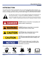
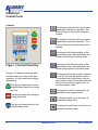
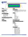
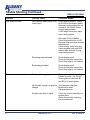
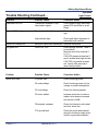
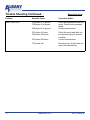
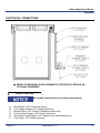
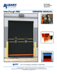
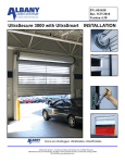
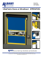
PN: 001011 Version 1.30 Rev: 4/29/2010 UltraFabric Doors w/ UltraSmart OPERATION Doors are Ultra-Tough, Ultra-Reliable, and Ultra-Affordable. Albany Door Systems - A Company of Albany International Corp. All Rights Reserved 1080 Maritime Drive, Port Washington, WI 53074 - 975-A Old Norcross Road, Lawrenceville, Georgia 30046 262-268-9885 www.albanydoors.com STATEMENT OF WARRANTY UltraFabric, RapidRoll 230, RapidRoll 355, RapidRoll 670 High Speed Doors ONE-YEAR WARRANTY ON MECHANICAL AND ELECTRICAL COMPONENTS Albany Door Systems warrants to the original owner of the door that the mechanical and electrical components will be free from defects in material and workmanship for a period of one (1) year from the date of shipment. Vinyl fabric material, mesh screen material and transparent (PVC) polyvinyl chloride material is warranted for one (1) year. Two (2) ply panel material is warranted for two (2) years and three (3) ply panel material is warranted for three (3) years. Only defects brought to the attention of Albany Door Systems during the warranty period will be covered by this warranty. Albany Door Systems will replace component parts covered by this warranty, which are found to be defective upon inspection by an Albany Door Systems representative. Installation or use of parts other than those authorized by Albany Door Systems will void this warranty. PARTS AND ASSEMBLIES sold separately by Albany Door Systems that fail due to defects in material or workmanship within ninety (90) days from the date of shipment will be replaced under warranty provided installation has been carried out in accordance with all Albany Door Systems procedures. This warranty is limited to providing a replacement part only. This warranty does not cover freight, special charges, or any costs associated with the installation of the replacement part. This warranty covers material failure under normal wear conditions; it does not cover damage caused by collision or other abuse of the product. Adjustments made to the control panel or to the mechanical operation of the door without the authorization of Albany Door Systems will void this warranty. Any changes made to product configuration without the express written approval from Albany Door Systems may null and void this warranty. Albany Door Systems’ obligations under this warranty are limited to repairing or replacing the defective part including labor and Albany Door Systems shall not be responsible for any other losses or damages due to the operation of any door or parts covered by this warranty. Warranty parts will be shipped regular ground freight at the expense of Albany Door Systems. This warranty shall be void in its entirety if the failure of any product shall be caused by any installation, operation, or maintenance of the product which does not conform with the requirements set forth by the seller in the applicable product manuals or is in the result of any cause other than a defect in the material or workmanship of the product. No other oral or written representations made by Albany Door Systems or its agents are a part of this warranty unless specifically set forth in writing by an authorized Albany Door Systems official. THE ABOVE SET FORTH WARRANTY IS SELLER'S SOLE WARRANTY. SELLER MAKES NO OTHER WARRANTY OF ANY KIND WHATSOEVER, EXPRESSED OR IMPLIED; AND ALL IMPLIED WARRANTIES OF MERCHANTABILITY AND FITNESS FOR A PARTICULAR PURPOSE WHICH EXCEED THE AFORESTATED OBLIGATION ARE HEREBY DISCLAIMED BY SELLER AND EXCLUDED FROM THIS AGREEMENT. WARNING Do not install, operate or service the product unless you have read and understand the safety practices, warnings, installation and maintenance instructions contained in this manual. Albany Door Systems - A Company of Albany International Corp. All Rights Reserved 1080 Maritime Drive, Port Washington, WI 53074 - 975-A Old Norcross Road, Lawrenceville, Georgia 30045 262-268-9885 or 877-925-2468 v4202010 1 Manual #001011 Rev. 4/29/2010 Albany High Speed Doors Operation INTRODUCTION The contents of this manual are designed to help you operate and maintain Albany UltraLite™, UltraFast™, UltraCool™, and UltraFreeze™ high speed doors. DO NOT operate or perform maintenance on the high speed door unless you have read through the instructions in this manual. The safety alert symbol is used to identify safety information about hazards that can result in personal injury. A signal word (DANGER, WARNING, or CAUTION) is used with the safety alert symbol to indicate the likelihood and the potential severity of injury. In addition, a hazard symbol may be used to represent the type of hazard. DANGER indicates a hazard that, if not avoided, will result in death or serious injury. WARNING indicates a hazard that, if not avoided, could result in death or serious injury. CAUTION indicates a hazard that, if not avoided, might result in minor or moderate injury. CAUTION, when used without the alert symbol, indicates a situation that could result in damage to the door. NOTICE is used to inform you of a method, reference, or procedure that could assist with specific operations or procedures. Other symbols that may be used in this manual are: Lock Out / Tag Out Version 1.3 Crushing Fire Manual #001011 Shock Read Manual 2 UltraSmart Control Panel Controls This key pad opens the door at a slower speed than normal door operation. The door will open as long as the key pad is pushed. This key pad closes the door at a slower speed than normal door operation. The door will close as long as the key pad is pushed. This key pad sets the time delay of the door closing once it has reached the selected open position in manual mode. Figure 1 Control Panel Key This key pad sets the time delay of the door closing once it has reached the selected open position in automatic mode. Display: The display shows operation, functions and error codes of the door operation. It is also used when setting adjustments. This key pad resets error codes, holding it for five (5) seconds will enter the menu. This button is also used while in the program mode to leave the present level and return to the previous program level, or exit the program mode. This key pad opens the door and stops the delay timer from closing the door. This key pad stops the opening or closing of the door. This key pad closes the door and stops the delay timer. 3 This key pad is used to select menu options while in the program mode. This key pad scrolls up in the menu, or increases a setting value. This key pad scrolls down in the menu, or decreases a setting value. Manual #001011 Rev. 4/29/2010 Albany High Speed Doors Operation Control Panel Display The display on the front of the control panel shows two lines of information. The top line displays system status and the second line displays details of the function or specifics of errors. Normal Operation During startup the display will show the software version programmed into the control panel and whether or not the door is ready for normal operation. Once the software has booted the door is ready for operation, the top line will display “Door Ready” unless there is an error detected. During normal operation the top line will display the current door status, with respect to movement or timers. “Door Ready” will be displayed while in standby mode, if no errors are present. The second line on the display will show the activator name for the function, or the safety device that triggered an action. The activator can be a manual input signal from the light curtain or reversing edge, or a breakaway switch input. There can be normal operation with the top line displaying “Door Ready” and the display second line showing a warning. The “Open: Delay timer Active” display is shown when the door is open and a timer function is operating to delay the door from closing. A “Preventer” code may be displayed if a condition exists to prevent the door from closing such as a disruption of the light curtain or a door bottom edge breakaway. The timer is re-armed if a “Preventer” condition exists. If any of the warnings shown on page six (6) except for “RevEdge Was Tripped” is displayed, please contact Albany Door Systems for diagnosis and repair. If the bottom line displays “RevEdge Was Tripped” it indicates that the door is open due to a reversing edge trip during the previous close cycle. The diagram show on page six (6) shows examples of normal operation displays. Operator Service Changing the Door Closing Time Delay In normal operation the Auto time delay selects the delay time before closing the door once it has reached the selected open position. To increase the time that the door waits before closing: Press the time delay will be displayed in seconds at a flashing cursor. If no key pad is pressed the controller will automatically return to normal operation after approximately four (4) seconds. Press the or to change the time delay in second intervals. After four (4) seconds the display will return to normal operation and the time will be stored in memory. If the time is set to “00” with the Man 1 Close Delay the door will remain open until this activator is triggered. Seating the Door in the Tracks In the event that the door bottom bar separates from a side track, do not attempt to force the bottom bar end(s) back into the track. The BacFlap™ Auto-Reset System will reset the door for normal operation. Version 1.3 Manual #001011 4 Line One (1) Text Line Two (2) Text Startup: R-Bac Industries Door Not Ready Normal Operation: Door ready Opening: Opening — Full Opening — Part Open: Delay Timer Active Auto1 Close Delay Auto2 Close Delay Man1 Close Delay Man2 Close Delay DTC Timer Open Commanded :Delay Timer Active: DTO Timer (Display shown during a count - down of the timer.) Closing: Closing Normal: Warning Door Ready Startup: Version n.m Normal Operation: 0000000 The zeros indicate the number of door operations. The counter will advance with each full or partial door opening. Version n.m (shown until first cycle) Opening: Auto 1 Auto 2 Man 1 Man 2 Open Pb Open On Panel Photo 1 (Front) Photo 2 (Rear) Reversing Edge Breakaway Open: Delay Timer Active: (Preventer, if any) Open Commanded :Delay Timer Active: Closing: Auto 1 Auto 2 Man 1 Man 2 Close Pb Close on Panel Normal: Warning Encoder Low Battery Module D Loop Open Module D Loop Short Module D Loop Error Module D Loop1 Open Module D Loop1 Short Module D Loop1 Error Module D Loop2 Open Module D Loop2 Short Module D Loop2 Error RevEdge Was Tripped 5 Manual #001011 Rev. 4/29/2010 Albany High Speed Doors Operation DO NOT reset the door until the break away flap(s) are out of the side rails on th eside away from the wall. Pull the bottom rail of the door away from the wall so the break away flap or flaps are on the front of the side rails away from the wall. Note: After the door bottom bar separates from a side track, when the key pad is pressed the door will open higher than normal operation. It will open to the break away limit setting. Press to automatically FULLY open the door; or, press and hold the to manually open the door high enough for the flaps to clear the guides at the top of the side rails. When using Press the key pad DO NOT raise the door higher than necessary. to close the door. The bottom bar ends will automatically track behind the guides and back into the side rails. The door control will reset itself to the automatic mode. Adjustments Door Limit Adjustments Door limit adjustments are used to set four heights that the door opens and closes to. There are four (4) heights that the operator can set; Closed Limit, Full Open Limit, Partial Open Limit, and Break Away Reset Limit. The Closed Limit should always be checked for correct height or set before the other limits are set. When any limit is set all of the limits should be checked or set. Closed Limit Used to set the fully closed position of the door. The door controller uses this position as the “zero” position to establish the height that the door moves to for two (2) open positions and the break away position. The Open, Partial, and Break Away limits are all relative to the Closed Limit. If the closed limit is reset to a different position, all the other settings will change relative to the new Closed Limit Setting. Full Open Limit Used to set the height that the door opens fully to. Partial Open Limit Used to set the height that the door opens to if it is programmed for a lower opening in addition to the fully open position. Break Away Reset Limit Used to set the height that the door will open to so the bottom rail can be seated in the side rails after it has been broken out of them. This height is set higher than the Full Open Limit. Version 1.3 Manual #001011 6 Periodic Maintenance Albany Door Systems high speed doors are engineered for low maintenance operation. The door should be visually inspected daily for wear and tear, and operated to verify functions. Quarterly maintenance should be performed to clean components and to check all safety functions and check for mechanical and electrical integrity. Daily Inspection 1. Inspect the door fabric for wear or damage. 2. Operate the door through several openings and closings. Verify that the door seats against the floor and that the door fabric remains tight and does not wrinkle. Verify that the door opens fully, slightly beyond the wall opening, and does not open too far. If the door does not seat against the floor properly or opens to the wrong position, refer to “Setting Door Limit Adjustments”. If the door fabric has diagonal wrinkles the door fabric roll at the top of the door is not level and perpendicular to the side rails. Leveling adjustments should be made as soon as possible to prevent wear or damage. Refer to the installation instructions or contact Albany Door Systems. 3. With the door closing, place an object through the light curtain, or photoeyes, on each side of the door. Verify that the door stops immediately. 4. If a multiple panel door is installed, check at each end of the ribs to verify that they are in place and centered. 5. Inspect the coiled electrical wire for wear or damage. 6. Check the light curtain slots for dirt or dust accumulation and clean as necessary. Do not stand under the door when performing the following inspection. If the bottom bar reversing switch is not functioning correctly injury can occur. 7. While the door is closing, tap the bottom of the door edge wand verify that the door stops and reverses to a fully open position. 7 Manual #001011 Rev. 4/29/2010 Albany High Speed Doors Operation Periodic Maintenance Continued… Quarterly Inspection 1. Perform daily inspection. 2. Check all mounting hardware and verify that all nuts and bolts are tight. Hardware includes: wall anchors, cover hardware, motor mounting hardware, and bearing bolt nuts. 3. Check the break away function by performing the following steps: Stop the door so the bottom rail is between waist and chest high. Push the bottom bar out of one of the side columns. Press the open key pad and verify that the door opens to the break away opening height and that the bottom bar centers in the side rails. Press the close key pad and verify that the bottom rail is centered and the door closes fully. 4. Inspect all side and top weather seals for wear or damage. Troubleshooting DISPLAY OR DOOR Problem Possible Cause Corrective Action No control or VFD display. Loss of main power. Check with meter across L1-L2,L2-L3,L1-L3 Blown Fuse Check with Meter: Across 1L1-1L2, 1L2-1L3,1L1-1L3 Across 2L1-2L2, 2L2-2L3, 2L1-2L3 Loss of power. Check with meter across 1L1-1L2 at control transformer. Blown fuse. Use meter to check for 24V between wired H_ terminals on top of transformer and between XF and X2 on bottom of transformer. No display or LED’s light on module panel. E stop jumper loose or miss- Verify that jumper is between 1A and 1B on ing. terminal strip of module board. Door will not open. Version 1.3 If E stop button present. Check to see if E stop button activated. No input signal at module A Check activation input by pressing corresponding test button, LED should light and door open. If door opens: faulty activator or wiring to module. If door does not open by test button: faulty module. Manual #001011 8 Trouble Shooting Continued... DISPLAY OR DOOR Problem Possible Cause Corrective Action Door does not close. Held open by safety input or ac- Check display readout. Check tivator input. for lit LED on modules A and B. Remove corresponding wire on module A. For lit LED-if door closes: faulty activator. If LED stays lit and door stays open: faulty module. Held open if loop installed. Check loop module for lit LED. Remove loop wires from module terminal strip. If door closes: faulty loop wire. If door remains open and LED stays lit after removal of loop wires: faulty module. Door does not open or close. Reversing edge activated. Check display reset. Check for bad wire connection. Check that edge is not pinched. Breakaway activated. Check display reset. Check for bad wire connection. Check that edge is not pinched. Brake not disengaging. Check power at terminals 5 and 6 below module C for 24 VAC. Check power at terminals B1 and B2 for 3 phase power. No encoder change, no position Door jammed: clear jam change. Broken drive shaft. Call manufacturer. Encoder com loss of signal. 9 Manual #001011 Check for loose connections or broken cable. Check for encoder mounting. Call manufacturer. Rev. 4/29/2010 Albany High Speed Doors Operation Trouble Shooting Continued... Light Curtain Problem Possible Cause Corrective Action Red alarm LED on. Transmitter disabled no synchronization signal. Check power supply and cable green LED should be on at all times. Yellow LED flashing. Sever electrical interference. Remove cables from high voltage. High ambient light. Check and adjust alignment of transmitter and receiver. Yellow LED always off. Receiver cannot see transmitter. Remove obstruction. No green LED. Loss of 24 VDC Check across terminal 1 and 4 on module B: Remove wires from terminal 1, 2, 3, 4. If 24 VDC present at terminal 1 and 4: isolate faulty light curtain. If 24 VDC not present at terminal 1 and 4 after removal of wires: faulty module. Problem Possible Cause Corrective Action Motor drive fault F3 power loss. Check incoming power. F4 undervoltage. Check incoming power for low voltage or power interruptions. F5 overvoltage Check for incoming power. F6 motor stalled. Increase accel time or reduce load so drive does not exceed set current in A089. F8 heatsink overheat. Check for blocked or dirty heat sink fins, check fan. F13 ground fault. Check the motor and external wiring for the drive output terminals for a grounded condition. Version 1.3 Manual #001011 10 Trouble Shooting Continued... Motor Drive Fault Problem Possible Cause Corrective Action Motor Drive Fault F38 phase U to ground. F39 phase V to ground. Check wiring between drive and motor. Check motor grounded phase. Contact manufacturer. F40 phase W to ground. F41 phase UV short. F42 phase UW short. F43 phase VW short. F70 power unit. 11 Manual #001011 Check the motor and drive output terminal wiring for shorted condition. Contact manufacturer. Recycle power. If fault does not clear, call manufacturer. Rev. 4/29/2010 Albany High Speed Doors Operation ELECTRICAL CONNECTIONS REFER TO INDIVIDUAL DOOR SCHEMATICS FOR SPECIFIC DETAILS ON OPTIONAL EQUIPMENT.. CONDUIT ROUTING All conduit and electrical connections must come in -A-B-C-D-E-F- Motor/Brake—3/4” Conduit (all doors) Low Voltage Signals—3/4” Conduit (all doors) Defrost Wiring—3/4” Conduit (UltraFreeze doors only) Primary Power Supply—3/4” Conduit (all doors) Secondary Power Supply—3/4” Conduit (some UltraFreeze doors) Floor Loop—1/2” Conduit (optional) Version 1.3 Manual #001011 12 WIRE STRIP GAUGE MOTOR WIRING ¼” 8" 6" ¾” MOTOR WIRE CONDUIT BRAKE WIRES DRILL ONLY INTO BOTTOM OF BOX USE MINIMUM ¾” CONDUIT ¼” T2 MG T1 SEPARATE FOIL SHIELD MG SEPARATE FOIL SHIELD T3 6" B1 MG B2 NOTE: MOTOR WIRES TO CHANGE DIRECTION OF MOTOR ROTATION – SWITCH T1 AND T2 ENCODER WIRING WIRE STRIP GAUGE ¼” ¾” LOW VOLTAGE CONDUIT ENCODER, SAFETY, ACTIVATION 4" DRILL ONLY INTO BOTTOM OF BOX USE MINIMUM ¾” CONDUIT TB2 TB3 TB1 TB1 TB4 13 Manual #001011 Rev. 4/29/2010 Albany High Speed Doors Operation SAFETY WIRING ¾” LOW VOLTAGE CONDUIT ENCODER, SAFETY, ACTIVATION H 5 TERMINALS AVAILABLE DRILL ONLY INTO BOTTOM OF BOX USE MINIMUM ¾” CONDUIT BLACK WIRES FROM ALL TRANSMITTERS ARE NOT USED LIGHT CURTAINS RECEIVER TRANSMITTERS - GREEN “POWER” LIGHT ONLY RECEIVERS – STATUS INDICATORS SHOWN BELOW PHOTO EYE WIRING CONNECTIONS RECEIVER #1 MODULE – B TERMINALS BLACK WHITE 2 BROWN 1 BLUE 4 TRANSMITTER TRANSMITTER #1 Version 1.3 ERROR BLOCKED OK WHITE 3 BLACK RECEIVER TRANSMITTER TRANSMITTER #2 (optional) Manual #001011 RECEIVER #2 (optional) 14 ACTIVATION WIRING N TOP 3 TERMINALS H NEXT 5 TERMINALS MANUAL ACTIVATORS MODULE - A TB2 1 2 3 CONNECT AS “NORMALLY OPEN” 4 5 6 H MODULE - A TB3 HERKULES™ MOTION SENSOR H BROWN GREEN N WHITE PINK Connect GRAY for Person Detection 1 2 3 4 5 6 GRAY RED Connect RED for Vehicle Detection MODULE - A TB3 FALCON™ MOTION SENSOR H 1 2 3 4 5 6 GREEN RED WHITE N BLACK REMOTE CONTROL H H N MODULE - A TB2 1 GRAY 2 3 4 5 6 GRAY RED BLACK TB3 1 2 TB4 3 4 5 MODULE - D 6 LOOP DETECTOR (optional) 15 Manual #001011 Rev. 4/29/2010 Albany High Speed Doors Operation DEFROST WIRING Albany doors may be equipped with one of the following optional systems: · · · · Heated Blowers IR Lamps IR Lamps & Unheated Blowers Unheated Blowers Use 18AWG or larger wires for all connections to RED terminal blocks. Use 12AWG or larger wires for all connections to BLACK terminal blocks. ¾” DEFROST WIRE CONDUIT DRILL ONLY INTO BOTTOM OF BOX CONNECT TERMINALS 28 & 29 TO 120VAC HEAT TAPE USE MINIMUM ¾” CONDUIT LOCATED IN JUNCTION BOX ON HEADER 6 LOW VOLTAGE WIRES - 13, 14, 15, 16, 17, 18 HEA TED BL OWE RS 6 HIGH VOLTAGE WIRES - 19, 20, 21, 22, 23, 24 3 IR LA MPS HIGH VOLTAGE WIRES - 25, 26, 27 4 UNH LOW VOLTAGE WIRES - 13, 14, 16, 17 IR L EAT AMPS ED B LOW ERS 9 HIGH VOLTAGE WIRES - 19, 20, 21, 22, 23, 24, 25, 26, 27 UNH 4 LOW VOLTAGE WIRES - 13, 14, 16, 17 EAT ED B L OWE RS 6 HIGH VOLTAGE WIRES - 19, 20, 21, 22, 23, 24 Version 1.3 Manual #001011 16 ENABLING THE WIRELESS SAFETY SYSTEM If the door is equipped with Albany’s Wireless Safety System (indicated by the lack of a coil cord), the following steps must be taken to initialize the communications:: 1. Locate the RFID number on a sticker on the pull strip. 2. Setup the UltraSmart™ Controller according to the procedure below: 3. Pull out the strip. 4. Test the system. UltraSmart™ Controller Settings Press and hold until “LIMIT SETUP” is shown on the display Press until “WIRELESS SETUP” is shown; Press Press until “BOTTOM BAR ID” is shown; Press Change the number to the RFID number on the bottom bar label using Press to store the value and press and until “DOOR READY” is displayed Thoroughly test the system to determine if all sensors/switches are functioning properly. Make sure you can answer “yes” to the following questions: Does the door reverse when the reversing edge is tripped upon closing? Does the UltraSmart™ controller recognize the left-side breakaway switch? Does the UltraSmart™ controller recognize the right-side breakaway switch? If you cannot answer “yes” to all the above questions, check all wiring connections and ensure the RFID is set to the same number that is labeled on the wireless bottom bar module. 17 Manual #001011 Rev. 4/29/2010 Albany High Speed Doors Operation UltraSmart™ STARTUP PROCEDURE Albany’s UltraSmart™ control system is designed to accommodate numerous option modules and future technological advances. This manual will address necessary settings for the standard options; however, optional modules and special applications may require additional steps to be taken for proper setup. Refer to the control schematic shipped inside the panel enclosure for additional electrical and setup details. SETTING DOOR LIMITS NOTE: SAFETY DEVICES WILL PREVENT THE DOOR FROM CLOSING IF ACTIVATED DUR- 1) Press and hold until “LIMIT SETUP” is shown on the display; Press 2) “CLOSED LIMIT” should be displayed; Press 3) Use 4) Press 5) Use 6) Press 7) Use and/or to bring the door to the full closed position; Press “FULL OPEN LIMIT” should be displayed; Press and/or to bring the door to the full open position; Press “PARTIAL OPEN LIMIT” should be displayed; Press and/or to bring the door to the partial open position or set the same as the full open position if not used; Press 8) Press 9) Use Version 1.3 “BREAKAWAY RESET LIMIT” should be displayed; Press and/or to bring the door to the breakaway reset position; Press Manual #001011 18 The Open, Partial, and Breakaway Limit are all relative to the Closed Limit. If the Closed Limit is reset to a different position, all SETTING SYSTEM OPTIONS 1) Press and hold 2) Press Use until “LIMIT SETUP” is shown on the display; Press until “SYSTEM OPTIONS” is shown; Press and/or to cycle through the available options; Press and/or to change the value; Press to edit that option. Use 3) When finished—press to store that value until “DOOR READY” is displayed SETTING TIMERS 1) Press and hold 2) Press Use until “LIMIT SETUP” is shown on the display; Press until “SET TIMERS” is shown; Press and/or to cycle through the available options; Press and/or to change the value; Press to edit an option. Use 3) When finished—press 19 to store that value until “DOOR READY” is displayed Manual #001011 Rev. 4/29/2010 Albany High Speed Doors Operation Version 1.3 Manual #001011 20 21 Manual #001011 Rev. 4/29/2010 Albany High Speed Doors Operation Version 1.3 Manual #001011 22 23 Manual #001011 Rev. 4/29/2010 Albany High Speed Doors Operation Version 1.3 Manual #001011 24 25 Manual #001011 Rev. 4/29/2010 Albany Door Systems - A Company of Albany International Corp. All Rights Reserved 1080 Maritime Drive, Port Washington, WI 53074 - 975-A Old Norcross Road, Lawrenceville, Georgia 30046 262-268-9885 www.albanydoors.com