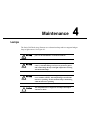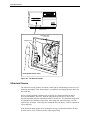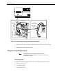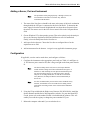
1
LIQUID CHROMATOGRAPHY
SERIES 200
DIODE ARRAY DETECTOR II
User’s Manual
Series 200
Diode Array Detector II
User’s Manual
Release History
Part Number
0993-6475
0993-6475
Release
A
B
Publication Date
September 1999
December 2001
Any comments about the documentation for this product should be addressed to:
User Assistance
PerkinElmer
710 Bridgeport Avenue
Shelton, CT 06484-4794
Or emailed to: [email protected]
Notices
The information contained in this document is subject to change without notice.
Except as specifically set forth in its terms and conditions of sale, PerkinElmer makes no warranty of
any kind with regard to this document, including, but not limited to, the implied warranties of
merchantability and fitness for a particular purpose.
PerkinElmer shall not be liable for errors contained herein for incidental consequential damages in
connection with furnishing, performance or use of this material.
Copyright Information
This document contains proprietary information that is protected by copyright.
All rights are reserved. No part of this publication may be reproduced in any form whatsoever or translated
into any language without the prior, written permission of PerkinElmer, Inc.
Copyright © 1999 - 2004 PerkinElmer, Inc.
Produced in the U.S.A.
Trademarks
Registered names, trademarks, etc. used in this document, even when not specifically marked as such, are
protected by law.
PerkinElmer, Turboscan200 and Turbochrom are registered trademarks of affiliates of PerkinElmer, Inc.
PerkinElmer is a registered trademark of PerkinElmer, Inc.
Contents
Safety and Regulatory Information
Electromagnetic Compatibility (EMC)---------------------------------------------------------------------------------1
United States ------------------------------------------------------------------------------------------------------1
Addresses---------------------------------------------------------------------------------------------------------------------1
Conventions used in this Manual ----------------------------------------------------------------------------------------2
Instrument Symbols and Warnings------------------------------------------------------------------------------------- S
Symbols ------------------------------------------------------------------------------------------------------------3
Warnings -----------------------------------------------------------------------------------------------------------4
Electrical Warnings --------------------------------------------------------------------------------------------------------5
Quality Control/Good Laboratory Practices---------------------------------------------------------------------------6
Quality Control ---------------------------------------------------------------------------------------------------6
Certificate of System Control ----------------------------------------------------------------------------------6
Instrument Performance Verification (IPV)-----------------------------------------------------------------6
Routine Inspection and Suitability Test----------------------------------------------------------------------6
Hazardous Chemicals ------------------------------------------------------------------------------------------------------7
Definitions in Warning for Hazardous Chemicals ---------------------------------------------------------7
Temperature, Humidity and Environment -----------------------------------------------------------------------------8
Storage Conditions -----------------------------------------------------------------------------------------------8
1. Introduction
Important ------------------------------------------------------------------------------------------------------------------ 1-1
About this Manual ------------------------------------------------------------------------------------------------------- 1-1
Conventions ---------------------------------------------------------------------------------------------------- 1-2
Chapter Content------------------------------------------------------------------------------------------------ 1-2
About the Detector ------------------------------------------------------------------------------------------------------ 1-3
Controls, Indicators and Connections ------------------------------------------------------------------------------- 1-4
Warnings and Precautions --------------------------------------------------------------------------------------------- 1-6
Warnings at the Back of the Detector --------------------------------------------------------------------- 1-6
Standard Detector Warnings -------------------------------------------------------------------------------- 1-7
Corrosion-------------------------------------------------------------------------------------------------------- 1-8
Air Bubbles ----------------------------------------------------------------------------------------------------- 1-8
Pressure Buildup----------------------------------------------------------------------------------------------- 1-8
Specifications------------------------------------------------------------------------------------------------------------- 1-9
2. Installation
About this Chapter------------------------------------------------------------------------------------------------------- 2-1
Preparing Your Laboratory -------------------------------------------------------------------------------------------- 2-1
Required Air Quality ----------------------------------------------------------------------------------------- 2-2
Sufficient Electrical Power ---------------------------------------------------------------------------------- 2-2
Solvents/Mobile Phase --------------------------------------------------------------------------------------- 2-2
Space Requirements ------------------------------------------------------------------------------------------ 2-3
Unpacking Your Detector ---------------------------------------------------------------------------------------------- 2-3
Electrical Requirements and Settings-------------------------------------------------------------------------------- 2-4
Space Requirements ------------------------------------------------------------------------------------------ 2-3
Detector Power Cord and Fuses ---------------------------------------------------------------------------- 2-5
The AC Line Cord ------------------------------------------------------------------------------------------------------- 2-5
Tubing Connections ----------------------------------------------------------------------------------------------------- 2-6
Powering up the Director----------------------------------------------------------------------------------------------- 2-6
3. Turbochrom Connections and Methods
About this Chapter------------------------------------------------------------------------------------------------------- 3-1
Hardware/Software Requirements ----------------------------------------------------------------------------------- 3-1
Communication Connections------------------------------------------------------------------------------------------ 3-2
Setting up an LC Method----------------------------------------------------------------------------------------------- 3-3
Setting the Autosampler Parameters----------------------------------------------------------------------- 3-4
Pump Configuration Information--------------------------------------------------------------------------- 3-6
Creating 200B/250 or 200Q/410 Pump Programs ------------------------------------------------------ 3-7
LC Detector Parameters-------------------------------------------------------------------------------------- 3-9
Setting Instrument Timed Events ------------------------------------------------------------------------ 3-10
Saving and Setting up the LC Method----------------------------------------------------------------------------- 3-11
4. Maintenance
Lamps ---------------------------------------------------------------------------------------------------------------------- 4-1
Ultraviolet Source --------------------------------------------------------------------------------------------- 4-2
Ultraviolet Source Replacement---------------------------------------------------------------------------- 4-3
Tungsten Lamp Replacement ------------------------------------------------------------------------------- 4-4
Illustrations
Safety and Regulatory Information
Location of warning labels------------------------------------------------------------------------------------------------4
1. Introduction
1-1. Front panel of the Series 200 Diode Array Detector------------------------------------------------------ 1-3
1-2. Rear panel of the Series 200 Diode Array Detector------------------------------------------------------- 1-5
2. Installation
2-1. Rear panel of the Detector with the system fuses shown ------------------------------------------------ 2-4
2-2. AC outlet configurations --------------------------------------------------------------------------------------- 2-5
2-3
Series 200 Diode Array Detector in a typical LC system------------------------------------------------ 2-6
3. Turbochrom Connections and Methods
3-1. Network (Client/Server) connections ----------------------------------------------------------------------- 3-2
3-2. Workstation connections for Turbochrom – 1 HPLC System ------------------------------------------ 3-3
3-3
Workstation
4. Maintenance
4-1. The Detector lamps ---------------------------------------------------------------------------------------------- 4-2
4-2. Removing the mercury timer switch for disposal---------------------------------------------------------- 4-4
4-3. Aligning the beam at the center of the cell focus mirror ------------------------------------------------- 4-6
Appendix A
A-1. Connections at the rear of the Diode Array Detector ---------------------------------------------------- A-2
Safety and Regulatory
Information
Electromagnetic Compatibility (EMC)
United States
This product is classified as a digital device used exclusively as industrial, commercial,
or medical test equipment. It is exempt from the technical standards specified in Part 15
of the FCC Rules and Regulations, based on Section 15.103 (c).
Addresses
To obtain assistance with the Series 200 Diode Array Detector, contact the Company as
described below:
PerkinElmer
Analytical Instruments
710 Bridgeport Avenue
Shelton, Connecticut 06484 USA
Tel: (800) 762-4000
Supplies, accessories, and replacement parts can be ordered directly from PerkinElmer
using the eight digit part numbers provided in the manual. To place an order or ask for
information, call your local PerkinElmer representative.
2 Safety and Regulatory Information
Conventions used in this Manual
In this manual the following graphic symbols and special text formats are used to set
apart important safety information.
A warning indicates an operation that could cause personal
injury if precautions are not followed.
A caution indicates an operation that could cause instrument
damage if precautions are not followed.
Notes emphasize significant information in a procedure or
description.
Series 200 Diode Array Detector User’s Manual 3
Instrument Symbols and Warnings
Symbols
There are three types of warning symbols that appear on the instrument:
This symbol indicates an operation (or condition on the
instrument) that could cause personal injury if precautions
are not followed. This can be any type of hazard.
When you see this symbol, refer to the safety pages in the
manual for further information.
Consulter les documents d’accompagnement.
This symbol indicates the danger of electric shock, if
precautions are not followed, due to the presence of high
voltage.
Attention. Risque de choc électrique.
This symbol indicates the danger of burns, if precautions are
not followed, due to the presence of heat in this area of the
instrument. There may also be hot surfaces that can be
easily touched.
AVERTISSEMENT. Surface chaude.
Additional graphic symbols used on the instrument are the following:
Indicates alternating current
Indicates the primary
protective grounding
terminal
O
Indicates the off position
of the main power switch
I
Indicates the on position
of the main power switch
4 Safety and Regulatory Information
Warnings
The following safety marking symbols and labels are affixed to the rear panel of the
instrument. (See Figure S-1):
DISCONNECT POWER BEFORE SERVICE.
GROUNDING CIRCUIT CONTINUITY IS VITAL FOR
SAFE OPERATION OF EQUIPMENT.
NEVER OPERATE EQUIPMENT WITH GROUNDING
CONDUCTOR DISCONNECTED.
For protection against fire hazard, replace only with same
type and rating of fuse.
Series 200 Diode Array Detector User’s Manual 5
Figure S-1.
Location of Warning Labels Found on the Rear Panel of the Series 200 Diode Array
Detector.
6 Safety and Regulatory Information
Electrical Warnings
Connect the instrument to an AC line power outlet that has
a protective ground connection. To ensure satisfactory and
safe operation of the instrument, it is essential that the
protective ground conductor (the green/yellow lead) of the
line power cord is connected to true electrical ground. Any
interruption of the protective ground conductor, inside or
outside the instrument, or disconnection of the protective
ground terminal may impair the protection provided by the
instrument.
Do not operate the instrument with any covers or parts
removed.
Do not attempt to make adjustments, replacements or
repairs to this instrument except as described in the
accompanying User Documentation. Only a PerkinElmer
service representative or similarly trained and authorized
person should be permitted to service the instrument.
Use only fuses with the required current rating and of the
specified type for replacement.
Series 200 Diode Array Detector User’s Manual 7
Quality Control/Good Laboratory Practices
Quality Control
The user should develop appropriate quality control procedures for the LC Diode Array
Detector (and the entire LC system) to ensure suitability for its intended use. These
procedures typically consist of periodic performance verifications and routine
inspections and suitability tests.
Certificate of System Control
Each Series 200 Detector is carefully built and tested in a controlled system in
accordance with the requirements specified in its applicable Final Assembly and Test
Specification.
Each instrument is certified to meet its functional and performance specification upon
release to shipment.
Instrument Performance Verification (IPV)
To maintain functional performance, PerkinElmer recommends a yearly Instrument
Performance Verification (IPV) of the Series 200 Diode Array Detector by a
PerkinElmer Service Engineer to ensure its operation within published specifications.
These tests consist of measuring the most important Diode Array Detector
characteristics, such as noise, drift, and wavelength accuracy. Certification is available
for regulatory compliance. Contact your local PerkinElmer Sales and Service office.
Routine Inspection and Suitability Test
Before any sample analysis with the Series 200 Diode Array Detector in the LC system,
a system suitability test, which closely resembles the intended assay, should be
performed to ensure that the LC system is operating within established criteria (e.g., peak
resolution, peak asymmetry, precision, retention time, column plate count, pressure
limits, signal/noise ratio, etc.).
While the Universal Test Mix (UTM), Part No. 0089-0893, can be used for a system
check, we recommend that you develop a separate system suitability test and acceptance
criteria for each of your assays.
8 Safety and Regulatory Information
Hazardous Chemicals
Before using mobile phase solvents, you should be thoroughly familiar with all hazards
and safe handling practices. Observe the manufacturer’s recommendations for use,
storage and disposal. These recommendations are normally provided in the material
safety data sheets (MSDS) supplied with the solvents.
Some chemicals used with this instrument may be hazardous
or may become hazardous after completion of an analysis.
The responsible body (e.g., Lab Manager) must take the
necessary precautions to ensure that the surrounding
workplace and that the instrument operators are not
exposed to hazardous levels of toxic substances (chemical or
biological) as defined in the applicable Material Safety Data
Sheets (MSDS) or OSHA, ACGIH, or COSHH documents.
Venting for fumes and disposal of waste must be in
accordance with all national, state and local health and
safety regulations and laws.
Definitions in Warning for Hazardous Chemicals
Responsible body. “Individual or group responsible for the use and maintenance of
equipment, and for ensuring that operators are adequately trained.” [per IEC 1010-1,
Amendment 2 ].
Operator. “Person operating equipment for its intended purpose.” [per IEC 1010-1,
Amendment 2 ].
OSHA: Occupational Safety and Health Administration (United States)
ACGIH:
American Conference of Governmental Industrial Hygienists
COSHH: Control of Substances Hazardous to Health (United Kingdom)
Series 200 Diode Array Detector User’s Manual 9
Temperature, Humidity and Environment
This instrument is designed for indoor use only.
This instrument is not designed for operation in an explosive
environment.
Safe Operation
This detector will operate safely between +10 and 35°C (+50 and 95°F) with an ambient
relative humidity of between 20 and 80% noncondensing.
Installation Category
This detector is able to withstand transient overvoltage according to Installation
Category II as defined in IEC 1010-1.
Pollution Degree
This equipment will operate safely in environments that contain nonconductive foreign
matter up to Pollution Degree 2 in IEC 1010-1.
Storage Conditions
The Series 200 Diode Array Detector may be stored under the following conditions:
• ambient temperature is −20 to +60°C (−68 to +140°F)
• ambient relative humidity is 20 to 80% noncondensing,
• altitude is in the range 0 to 12,000 m.
Introduction
Important
This manual contains important information regarding potential hazards that may arise
during the operation of the Series 200 Diode Array Detector. It is essential that the
Safety and Regulatory information preceding this chapter be read and thoroughly
understood by all users and potential users of the detector.
The Diode Array detector should be used according to the
instructions provided in the manual. If used otherwise, the
protection provided for the Diode Array detector might be
impaired.
About this Manual
This manual was written for a person who has developed a working knowledge of liquid
chromatography and understands:
•
•
•
the function of each major component in a liquid chromatography system
how to select a column based on the analysis that will be performed
the principles of solvent selection and sample preparation
If you require an introduction to these concepts, the following book is an excellent
reference: Practical Liquid Chromatography -- An Introduction by R.W. Yost, L.S.
Ettre, and R.D. Conlon, published by PerkinElmer (1980), Part No. 0993-9656.
1-2 Introduction
Conventions
The following conventions are used in this manual (see the Safety and Regulatory
Information preceding this chapter):
A warning indicates an operation that could cause personal
injury if precautions are not followed.
A caution indicates an operation that could cause instrument
damage if precautions are not followed.
Notes emphasize significant information in a procedure or
description.
Chapter Content
This chapter describes the detector, its controls and detector specifications (see Table 12).
The second chapter describes installation of the detector in your LC system, electrical
requirements and plumbing connections.
The third chapter is comprised of drawings (Figures 3-1 and 3-2) showing
communications connections for Turbochrom and the procedure for setting up an LC
method for running a test file.
Chapter 4, Maintenance, includes lamp replacement procedures:
•
•
replacing the deuterium (UV) lamp
replacing the tungsten (VIS) source (including an alignment procedure)
Series 200 Diode Array Detector User’s Manual 1-3
About the Detector
The Series 200 Diode Array HPLC (high-performance liquid chromatography) detector
is a high-performance photodiode array detector. It includes a dispersive, photodiodearray spectrometer system that continuously collects full-scan spectra of the analytes in a
flowing stream. The detector consists of the opto-electronic assembly and a data system;
the storage of spectral files is controlled by sending commands from the data system to
the spectrometer system.
CHANNEL
READY
Deuterium Lamp
ON/OFF Switch
UV
LINK READY
Tungsten Lamp
ON/OFF Switch
ACTIVE
VIS
ERROR
LINK POWER A
B
C
D
SYSTEM POWER
Series 200
Diode Array Detector
Access Cover
Link Status Indicator Lamps
Figure 1-1. Front panel of the Series 200 Diode Array Detector
The opto-electronic assembly consists of:
•
an optical bench with a flow cell
•
regulated deuterium and tungsten light sources
•
polychromator spectrograph
•
512-element photodiode array
•
power supplies and circuitry required to operate the detector and transmit data to the
data system.
The data system consists of an on-board microprocessor that communicates, via an RS
232 connection, with a host data system.
1-4 Introduction
Controls, Indicators and Connections
The controls, indicators and connectors on the front and rear panels of the detector are
described in the next two paragraphs.
On the Front Panel (Figure 1-1)
UV Switch
Press the switch to energize the deuterium lamp. When the lamp is
energized, the switch is lighted. Only energize the deuterium lamp when
the sample absorbs in the UV range (190-360 nm).
Wait two minutes after turning on the Power switch before
energizing the deuterium lamp.
VIS Switch
Press the switch to energize the tungsten-halogen lamp. When the lamp
is energized, the switch is lighted. Only energize the tungsten-halogen
lamp if the sample exhibits absorption in the VIS range (360-700 nm).
If you are using both UV and VIS lamps, turn on the VIS lamp
AFTER turning on the UV lamp.
To control the lamps from Turbochrom, both lamps must be
switched on prior to taking control from Turbochrom Navigator.
After performing Method Setup, you can turn the lamps on or off
using Hands On. See the Turbochrom Client/Server User's Guide
(P/N S270-2600-B).
Cell Carriage Holds the flow cell. When inserted, it keeps the flow cell in the correct
position in the optical path of the detector. To remove the cell carriage
from the detector, remove the access cover (see Figure 1-1) and loosen
the carriage retaining screw.
Inlet and
Outlet Lines
Provide connections (0.007 in. stainless steel tubing) to the outlet of
the HPLC column and the waste container.
Front Panel Indicator Lamps
The following indicator lamps are on the front panel of the detector (see Figure 1-1).
System Power lamp lights when the Power On/Off switch on the back panel is in the
ON position.
UV
lamp lights when the deuterium lamp is energized.
VIS
lamp lights when the tungsten-halogen lamp is energized
Series 200 Diode Array Detector User’s Manual 1-5
Link Status Indicator Lamps
Link Ready lights when a link is ready
Link Power lights when a link is powered on
Channel Status lamps
Three Channel Ready Lamps
Three Active Channel Lamps
Three Channel Error Lamps (Refer to the Turbochrom manual for error messages.)
On the Rear Panel (Figures 1-2 and 2-1)
Power Switch
An On/Off toggle switch located on the power entry module at the
right of the rear panel. Toggle the switch On to energize the
instrument chassis, the cooling fan, and the photodiode array
assembly.
Power Cord Connector
(Receptacle)
Accepts a standard, detachable, three-prong power cord.
Power Fuse Holder Includes two 6.3A, T type fuses for main power.
Lamp Adjustment
Thumb Wheels
For use by Service Representatives only.
Figure 1-2. Rear panel of the Series 200 Diode Array Detector
1-6 Introduction
Warnings and Precautions
Warnings at the Back of the Detector
The following warnings are placed on the back panel of the detector (see Figure S-1).
They contain information that you should be familiar with before operating the Diode
Array Detector:
DISCONNECT POWER BEFORE SERVICE.
GROUNDING CIRCUIT CONTINUITY IS VITAL FOR
SAFE OPERATION OF EQUIPMENT.
NEVER OPERATE EQUIPMENT WITH GROUNDING
CONDUCTOR DISCONNECTED.
For protection against fire hazard, replace only with the
same type and rating of fuse.
Double Pole/Neutral Fusing. The detector is configured with
Double Pole/Neutral Fusing for universal voltage
configuration. To avoid electrical shock, disconnect the
power supply before changing fuses. Disconnect the power
supply whenever the cover is removed.
Series 200 Diode Array Detector User’s Manual 1-7
Standard Detector Warnings
Read and understand the following warnings and precautions.
Solvents
Give careful attention to the hazards associated with the
solvents you are using. Refer to the safety data sheets
provided by the manufacturer. For example, Material Safety
Data Sheets (MSDS) in the USA.
•
Wear appropriate eye protection at all times when handling chemicals. Use safety
glasses with side shields, goggles, or full-face shields, according to the types of
chemicals you will be handling.
•
Wear suitable protective clothing, including gloves that are specifically resistant to
the chemicals being handled.
•
Always use clean solvents. Solvents that have been distilled in glass (HPLC Grade)
are highly recommended.
•
Filter the solvents through a 0.5-micron medium as an additional precaution.
•
Carefully use and store flammable solvents, which may form hazardous by-products
when the instrument is shut down, by following the recommended shutdown
procedure.
•
Check compatibility of solvent(s) with the type of column(s) being used.
•
Know the relative polarity and miscibility of the solvents being used.
Buffers
Exercise care when using buffers in conjunction with organic solvents. NEVER LEAVE
BUFFERS IN THE SYSTEM OVERNIGHT. Buffers left in the system can form salt
crystals that may cause premature pump seal failure, interfere with proper check valve
operation, and plug the connecting tubing or the detector flowcell.
To remove buffers, flush the system first with water, then with methanol or isopropanol.
Change the mobile phase from methanol or isopropanol to water before using buffers.
1-8 Introduction
Corrosion
All parts that contact the mobile phase are made of stainless steel, Teflon, PEEK, or
quartz. Some of these materials are extremely sensitive to acid chlorides. If you have
questions about your mobile phase, contact a Service Representative.
Table 1-1. Solvents Which May Corrode the Series 200 Diode Array Detector
Aqua Regia (80% HCl, 20% HNO3 )
Chloride salt solutions*
Chlorinated solvents
Halogenated solvents
Sulfuric Acid (Conc.)
* Titanium is more resistant to chloride salt solutions.
Air Bubbles
To prevent air from entering the system, and to ensure that pressure fluctuations do not
occur, observe the following precautions:
•
Ensure that the pump's solvent inlet filter is below the solvent level in the solvent
reservoir.
•
If the pump has not been used for an extended period of time, remove air bubbles by
connecting a priming syringe to the drain valve on the pump, opening the drain
valve, and fast-flushing the system to prime the pump. After priming the pump,
close the drain valve completely.
•
If bubbles are observed in the flow cell, degas the solvent and add back-pressure
device 0990-7126.
Pressure Buildup
Over time, you may notice a gradual increase in the system operating pressure. If you
observe pressure readings greater than 3.45 MPa (500 psi) above the normal operating
pressure of your analysis, check the following items:
•
If you are injecting clean samples and there is no other apparent cause for the
pressure buildup, remove, disassemble, and clean the injector.
•
If you are injecting dirty samples, the injector may be clogged or the column packing
material may have retained contaminated particulates. Remove and clean the
injector, and replace the column.
•
The column end fitting or column frit may be plugged. Replace the end fitting or frit
to relieve excess pressure. (Refer to the instructions supplied with the column.)
•
In-line filters may be plugged. Replace the filter element.
•
With the pump connected directly to the detector input, if you still experience excessive
pressure, the problem could be a plugged flowcell. You can flush, reverse-flush, or rebuild
the flowcell.
Series 200 Diode Array Detector User’s Manual 1-9
Specifications
Table 1-2. Specifications of the Series 200 Diode Array Detector
Detector Specification
Number of Diodes
Wavelength Range
Resolution
Absorbance Range
Wavelength Accuracy
Short-term Noise
Drift
Lamps
Flow Cells
Power Requirement
Power Consumption
Line Voltage Operating Range
Frequency
Line Cord
Fuse Rating Characteristics
120 VAC (P/N 0999-1662)
240 VAC (P/N 0999-1662)
Operating Conditions
Ambient Temperature
Ambient Relative Humidity (RH)
Altitude
Storage Conditions
Ambient Temperature
Ambient Relative Humidity
Altitude
Dimensions
Weight
Description
512
190 - 700 nm
4 nm observed (1.09 nm/diode)
−0.005 to +1.5 AUFS
±1 nm
±1 × 10⁻⁵ AU (average peak-to-peak noise
between 190 and 700 nm) (dry cell)
1 × 10⁻⁴ AU/hr
Deuterium and tungsten-halogen
10 mm path (12 µL) standard
4.5 mm path (5 µL) analytical
2 mm path (4 µL) preparative
Description
195 VA
100/240 VAC
50/60 Hz
See “The AC Line Cord” on page 2-5 of these instructions.
Description
6.3 A, 250 Volt, IEC Type T
6.3 A, 250 Volt, IEC Type T
Description
10 to 35°C
20 to 80% RH (non-condensing)
0 to 2000 m
Description
-20 to +60°C
20 to 80% RH (non-condensing)
0 to 12 000 m
Height: 19.7 cm (7.75 in.)
Width: 33.7 cm (13.25 in.)
Depth: 80.5 cm (22.75 in.)
20 kg (45 lb.)
1-10 Introduction
Installation
About this Chapter
The following paragraphs are included in this chapter to prepare you for installing the
Series 200 Diode Array Detector:
•
•
•
•
•
preparing your laboratory
unpacking your detector
electrical requirements and settings
tubing connections
powering-up the detector
Preparing Your Laboratory
Before installing your Series 200 Diode Array Detector, prepare your laboratory
according to the following guidelines.
2-2 Installation
Required Air Quality
To minimize contamination problems in your laboratory, provide a relatively dust-free
environment. Make sure that gases or vapors of the following kinds are not present at
levels that exceed federal, state, or local ordinances for continuous human exposure:
• flammable
• explosive
• toxic
• caustic
• corrosive
Make sure that your laboratory environment includes the following temperature and
humidity levels:
•
Ambient temperature between 10°C and 35°C
•
Constant relative humidity between 20% and 80% (without condensation)
Be careful when working with hazardous solvents, or solvents that produce hazardous
by-products.
Solvent vapor levels that are high enough to interfere with
detector performance should be considered hazardous to
someone who is continuously exposed to the vapors.
Sufficient Electrical Power
The Series 200 Diode Array Detector requires a grounded nominal 100, 120, 220, or
230/240 Vac source. Data processing equipment and other accessories require separate
outlets. (Refer to the appropriate equipment manual for the power requirements.)
To prevent degradation of the diode array detector's performance, the AC line voltage
must remain within ±10% of the nominal specified voltage. If you experience large
voltage fluctuations, install a voltage regulator between the diode array detector and AC
outlet.
Solvents/Mobile Phase
Use only HPLC grade solvents in all analyses. HPLC grade water and methanol (1 liter
each) are required for performance verification.
Series 200 Diode Array Detector User’s Manual 2-3
Space Requirements
The Series 200 Diode Array Detector is designed to sit on a benchtop; it is normally
plumbed into the LC autosampler as shown in Figure 2-3. A space approximately 20 cm
(8 in.) high is sufficient for the detector if nothing else is to be placed over (or on) it.
Figure 2-3 shows the Series 200 Diode Array Detector in a typical LC system.
The case is 33.7-cm (13.25 in.) wide, but additional space is required on both sides of the
detector: on one side for the tubing from the autosampler, and on the other side for the
tubing to the drain vessel. The case is 80.5-cm (22.75 in.) deep, but additional space is
required behind the unit to accommodate the power cord and cables to any other
connectors.
Unpacking Your Detector
Carefully unpack the Series 200 Diode Array Detector and check for obvious signs of
damage that could have occurred during shipment. Immediately report any damage or
missing items to the shipping carrier and Perkin Elmer.
A start-up kit is supplied with the detector. Refer to Table 2-1 and check the parts you
received against the parts listed in the table.
Table 2-1. Start-Up Kit for the Series 200 Diode Array Detector
Items Included
AC Line Cord*
Fuse, 6.3A, 250V, IEC Type T
1
/4 in. PEEK Fingertight Nut
Users Manual
Installation Disk
Cable, Ethernet Cat 5
Cable, Serial Data
Harns, Link to Detector
Cable, Service 9PF to 9PF Dsub, 6'
PerkinElmer
P/N
Quantity
0998-8986
0999-1662
0992-0513
0993-6475
N292-2060
55-0214**
55-0213**
55-A589**
55-A588**
*Customers located outside of the U.S. must order a line cord that is appropriate for their location.
**Vendor (GTI) Part Number
1
2
2
1
1
1
1
1
2-4 Installation
Electrical Requirements and Settings
The Series 200 Diode Array Detector can operate at 50 or 60 Hz and requires a
grounded outlet that provides a nominal 100, 120, 220, or 230/240 VAC
source. If the electrical supply voltage in your laboratory produces large AC
line voltage fluctuations, install a voltage regulator between the AC line
voltage outlet and the Series 200 Diode Array Detector. Instrument
grounding is required, and is accomplished by a third wire in the AC linevoltage outlet box. If your electrical outlet does not contain a ground,
contact your local electric company.
LINK POWER
Warning
Disconnect supply cord before opening.
Grounding circuit continuity is vital for
safe operation of equipment. Never
operate equipment with grounding
conductor disconnected.
Warning
SET UP
For protection against fire hazard,
replace only with same type and
rating of fuse.
ON
OFF
VIS
Power
Switch
SERIAL/HOST
100 -240 - VAC
50/60 Hz, 195VA
CONTROL
GPIB
FUSES - 6.3A T 250V
AUX F AUX E
INST D
INST C
INST B
INST A
System Fuses
Fuse Board
Fuse Holder
Fuse
6.3A, 250 Volt, Type T
(P/N 0999-1662)
(1 of 2)
Fuse Board Lock Tab
Figure 2-1. Rear panel of the Detector with the system fuses shown
Series 200 Diode Array Detector User’s Manual 2-5
Detector Power Cord and Fuses
The Diode Array Detector power entry module and system fuses are located at the right
of the detector’s back panel (see Figure 2-1).
Installing/Replacing the Fuses
The unit is shipped with two fuses (see Figure 2-1) installed. To replace a fuse, proceed
as follows:
1. Make sure the unit is disconnected from line power.
2. Refer to Figure 2-1 and remove the fuse holder from power entry module at the back
of the detector.
3. Lift the fuse-board lock tab and remove the fuse board from the fuse holder.
4. Install, or remove and then install, fuse(s) in the fuse holder. Use only
6.3-amp T type fuses P/N 0999-1662.
5. Reconnect the detector to line power.
The AC Line Cord
Do not disconnect or defeat safety ground on the power cord.
Ground is necessary for safe operation of the Series 200 Diode
array detector and proper functioning of the electronic
circuitry.
The line cord should have the electrical rating and plug
appropriate for your location. See Figure 2-2 for the correct
cord.
1. Select the proper line cord for your location (Figure 2-2).
2. Insure that the power switch is off and insert the line cord plug into the AC supply.
North America
NEMA-5-15
0999-1420
Old British Standard
BS 546
India
0999-1423
Europe
CEE 7
"Schuko"
0999-1415
British Standard
BS 1363
United Kingdom
0999-1414
Europe
Switzerland
0999-1413
Australia
ETSA S/86
0999-1417
Europe
Italy
0999-1422
Israel
0999-1424
Denmark
0999-1416
Figure 2-2. AC outlet configurations
2-6 Installation
Tubing Connections
The flow cell is shipped with 0.007 in. ID standard stainless steel tubing installed. All
connections are made with standard1/16-in. fingertight fittings. In Figure 2-3, the Series
200 Diode Array Detector is shown plumbed in a typical LC system.
From Pump
2
1
Drain
3
6
Loop
(1 to 4)
To Column
Bottom View of the
Injector Valve
4
5
Series 200 Autosampler
Drain
3
2
CHANNEL
READY
UV
LINK READY
ACTIVE
VIS
ERROR
LINK POWER A
B
C
D
SYSTEMPOWER
Series 200
Diode Array Detector
Waste
Series 200
Diode Array Detector
Series 200 LC Pump
Solvent
In-Line Solvent Filter (Optional)
Figure 2-3. Series 200 Diode Array Detector in a typical LC system
Powering up the Detector
After completing the installation of the Diode Array Detector, carefully read Chapter 3,
Turbochrom Connections and Methods before powering-up the detector.
Turbochrom
Connections and Methods
About this Chapter
In this Chapter, we discuss the hardware and software requirements when using the
Series 200 DAD detector with Turbochrom. We then show the Turbochrom electrical
(communication) connections and describe the procedure for setting up and running a
test file. For procedures for configuring Turbochrom and building a method, refer to
Chapters 3 and 5, respectively, of the Turbochrom Client/Server User’s Guide (P/N
S270-2600-B).
Hardware/Software Requirements
The following are the software requirements for using the Series 200 Diode Array
Detector with Turbochrom:
•
•
•
Turbochrom WS/CS (6.1 or greater)
TurboScan200
Spectral Acquisition Software that is included with the detector. Instructions for
using the software are on installation CD N292-2060.
3-2 Turbochrom Connections and Methods
Communication Connections
Figure 3-1. Workstation Connections – 1 HPLC System
Series 200 Diode Array Detector User’s Manual 3-3
Figure 3-2. Workstaion connections for Turbochrom – Multiple Systems
3-4 Turbochrom Connections and Methods
Figure 3-3. Client/Server Configuration
Setting up an LC Method
In the following paragraphs the autosampler, pump, and diode array detector parameters
are selected for the collection of chromatographic and spectral data.
To use specific values for the parameters, we set up the conditions for the analysis of the
universal test mix (P/N 0089-0893).
For configuration information and procedures for building a
method, refer to Chapters 3 and 5, respectively, of the
Turbochrom Workstation User’s Guide (P/N S270-1601).
Series 200 Diode Array Detector User’s Manual 3-5
From the Turbochrom Navigator screen, select Method Editor and create a new method
by selecting from the parameters and timed events listed below.
Setting the Autosampler Parameters
1. Select the Autosampler tab of the Instrument Control dialog box.
2. If you are using manual injection, select Manual. If you are using an autosampler,
select Autosampler and continue with Steps 3 through 20.
3. In the Injection Volume text box, enter the amount of sample that you want to inject.
(Make certain that this value is less than 50% of the Loop Size that you specify in
step 4.)
4. From the Loop Size list, select the size of the injection loop fitted to your
autosampler.
To enable the Fixed Mode option, where the injection volume is
equal to the loop volume, select a loop size value less than 50 µL.
5. To operate in Fixed Mode, set the value of the Fixed Mode list to On. This option
forces the Injection volume to be equal to the loop volume. Fixed mode is useful if
you are working with small sample sizes or applications that require high precision.
(You can only use Fixed Mode when the Loop Size value is less than 50 µL.)
6. In the Excess Volume text box, enter the amount of sample that you want withdrawn
from the vial in addition to the injection volume.
(This option prevents evaporation and contamination by isolating the actual plug of
sample to be injected as it is transported to the injection loop. This option is only
available if Fixed Mode is set to Off.)
7. In the Air Cushion text box, enter the amount of air that you want to insert between
the sample and flush solutions to prevent the two solutions from mixing.
3-6 Turbochrom Connections and Methods
8. From the Sample Syringe Size list, select a syringe volume.
9. From the Sample Speed list, select the speed at which you want the sample pump to
fill the injection loop.
(Slower speeds provide more reproducible injection volumes, particularly for viscous
samples.)
10. From the Needle Level, select the appropriate percentage.
(This value sets the height at which the sampling needle extracts the sample. It is set
as a percentage of the vial height, measured from the bottom of the vial.)
11. In the Inject Delay Time text box, enter the number of minutes that you want
between the pump's run start signal and when the sample injection occurs.
12. If you are using a Series 200 Autosampler, refer to “Creating Derivatization and
Dilution Programs.”
13. In the Flush Volume text box, enter the amount of flush solution that you want
pumped through the sampling system for each flush cycle.
14. From the Flush Speed list, select the speed at which you want the pump to flush the
system.
15. In the Flush Cycles text box, enter the number of flush cycles that you want to have
between injections when the method changes in a sequence.
(This value also specifies the number of flushes the autosampler performs when you
choose Flush Autosampler in the Hands On dialog box.)
16. In the Pre-Injection Cycles text box, enter the number of flush cycles that you want
before each sample injection or before each vial-to-vial transfer in sample processing
modes.
17. In the Post-Injection Cycles text box, enter the number of flush cycles that you want
after each sample injection or before each vial-to-vial transfer in sample processing
modes.
18. In the Post-Method Cycles text box, enter the number of flush cycles that you want
after each method is completed in a sequence.
19. Under Peltier Tray Control, set the temperature of the tray.
20. In the ± list, select a tolerance percentage to control when the system Peltier Tray
becomes ready. (The Peltier Tray will be ready to inject only if the temperature is
within the range of the temperatures that you set, plus or minus the value in the
tolerance section.)
Series 200 Diode Array Detector User’s Manual 3-7
Pump Configuration Information
The Pump Config tab of the Instrument Control dialog box lets you enter labels for
solvents and set other pump configuration parameters, such as the Ready Time and the
pressure units. The solvent labels you create appear in the Method Summary window and
on the Pump Program tab.
Setting Pump Configuration Parameters
1. Select the Pump Config tab of the Instrument Control dialog box.
2. In the Ready Time text box, enter the number of minutes that the pump remains in a
READY state, after which you want the pump to shut down. (A Ready Time of 999
means that the pump will continue in the READY state indefinitely.)
3. In the Standby Time text box, enter the number of minutes that the pump remains in
a READY state, after which you want the pump to change to the standby flow rate.
(A Ready Time of 999 means that the pump will continue to use the flow rate set in
the grid as long as the pump remains READY.)
4. In the Standby Flow text box, enter the pump flow rate for the standby mode.
5. From the Pressure Units list, select either PSI or BAR as the units for inlet pressure;
the choice depends on the instrument that you are using.
6. In the Max Pressure text box, enter the upper pressure limit, above which the pump
will shut off.
7. In the Min Pressure text box, enter the lower pressure limit, below which the pump
will shut off.
8. In the Solvent Names text boxes, enter the labels you want to use.
3-8 Turbochrom Connections and Methods
Creating 200B/250 or 200Q/410 Pump Programs
To create a pump solvent gradient program, or pump program, use the Pump Program tab
of the Instrument Control dialog box. This tab contains a table and a gradient curve,
which let you define the composition of the solvents at each step in the run. You can
change the table parameters and the curve either by editing the values in the table or by
dragging points on the curve with the mouse.
You can enter 10 rows, or steps, in the pump program. Step 0 is always the pre-run
equilibration, for which you enter Time, Flow, and Solvent values. The table for
200B/250 or 200Q/410 pumps has the following columns:
•
Time−duration of each program step
•
Flow−flow rate during each program step
•
A, B, C (Solvents)−percentage of each solvent at the end of each program step
•
D (Solvent)−The percentage of this solvent at the end of each program step. This
value adjusts automatically so that the sum of A, B, C, and D is 100.
•
Curve−type of gradient curve to use for this program step. The types of curve are
step (0), linear (1), convex (-1.1 to -9.9), and concave (1.1 to 9.9) for increasing
solvent percentage. The magnitude of the number determines the degree of
curvature.
Series 200 Diode Array Detector User’s Manual 3-9
To set pump-control parameters
1. Select the Pump Program tab of the Instrument Control dialog box.
The Program Time field displays the sum of the values in the
Time column for all the steps that you create. The Detector Time
field displays the data acquisition time of the analysis.
2. In Step 0 of the table, click in the Time, Flow, and solvent fields, and then enter
amounts for the equilibration step.
3. Enter the Time, Flow rate, solvent composition, and Curve type for each additional
program step.
(The Time field activates the other fields in each row, and the curve changes as you
enter each set of values. Depending on the specific pump that you are using,
Turbochrom completes the solvent percentage either for solvent B or for solvent D
so that the total solvent composition is 100 percent. Also, if you change the value of
solvent B or the value of solvent D, the value of solvent A adjusts so that the total
remains 100 percent.)
For the 250 pump, the resolution at which you can enter time
and flow values, changes across the allowed range. You can
enter times between 0 and 9.9 minutes to the nearest 0.1 minute,
but times between 10 and 999 minutes must be to the nearest
minute. Flow rates between 0 and 0.99 mL/min can be to the
nearest 0.01 mL/min, but flows between 1.0 and 10.0 mL/min
can only be to the nearest 0.1 mL/min. Turbochrom will beep if
your entry causes a change from one resolution range to another.
4. To reduce the amount of equilibration time after the first run, select Enable Solvent
Saver, and then enter the new amount of equilibration time to use after the first run
in the text box.
5. To turn the pump off at the end of the run without recycling to initial conditions,
select Shutdown In Final Conditions.
Only set this option for a “shutdown method,” which is run as
the last cycle in a sequence.
3-10 Turbochrom Connections and Methods
LC Detector Parameters
The Detectors tab of the Instrument Control dialog box is used to set detector
parameters:
•
Wavelength A(nm) and B(nm)−The wavelength selected to monitor Channels A
and B.
•
Bandwidth BW-A and BW-B − The bandwidth, or total wavelength range, around
the nominal selected wavelength for Channels A and B.
•
Spectral Acquisition parameters − which can be Off and Time. If Time is selected,
you will select the rate at which spectra will be selected.
To set Series 200 diode array detector parameters
1. Select the Detectors tab of the Instrument Control dialog box.
Chromatogram Acquisition Entries
2. Enter 254 (nm) for the Channel A Wavelength and 280 (nm) for the Channel B
wavelength.
3. Enter Bandwidths of 20 (nm) for both channels.
4. Enter 300 (nm) for both Channel A and Channel B Reference Wavelengths.
Spectral Acquisition Entries
5. Select the Time Mode.
6. Select value 1.136363 in the Spectra/s box.
Series 200 Diode Array Detector User’s Manual 3-11
Setting Instrument Timed Events
Use the Instrument Timed Events tab of the Instrument Control dialog box to select one
or more timed events from a predefined list, and enter the time at which you want the
event to take place. The events available depend on which instrument you have selected.
For a 900 Series Interface, you can choose events to set relays 1 through 7 on or off.
Another event, RVPRT, instructs the interface to read rack and vial information from the
attached autosampler at a specified time. For information about the instrument-timed
events for other supported instruments, refer to the documentation that came with the
instrument.
In the Graphic Method Editor, you can insert instrument-timed events directly on the
chromatogram at a specified time. For more information, refer to Chapter10 of the
Turbochrom Workstation User’s Guide, Editing a Method and Results Graphically.
Saving and Setting up the LC Method
See chapter 5 "Building a Method" of the Turbochrom Client/Server Users Guide (P/N
S270-2600-B). It provides an overview of the Turbochrom Method Editor and of
creating and modifying a method.
A method consists of instrument, processing, and calibration parameters, which are
described in chapters 6, 7, and 8, respectively, of the user’s guide.
3-12 Turbochrom Connections and Methods
Maintenance
Lamps
The Series 200 Diode Array Detector uses a deuterium lamp and/or a tungsten halogen
lamp as light sources. See Figure 4-1.
The deuterium lamp operates at high voltage. Remove
power to the instrument to avoid electrical shock.
The ultraviolet light produced by deuterium lamps will
cause eye and skin damage. Always wear protective glasses
and avoid looking directly at the light output when working
with deuterium lamps.
The deuterium lamp operates at high temperatures (in
excess of 200°C (390°F)). The lamp housing is hot when the
detector is operating. Do not touch the lamp or the housing
when the detector is operating.
The lamp filaments are fragile. Do not subject the lamp to
vibration or shock.
4-2 Maintenance
CHANNEL
READY
UV
LINK READY
ACTIVE
VIS
ERROR
LINK POWER A
B
C
D
SYSTEM POWER
Series 200
Diode Array Detector
Access Cover
Deuterium Lamp
(inside mount)
Tungsten Lamp
View behind Access Cover
Figure 4-1. The Detector lamps
Ultraviolet Source
The ultraviolet source produces an intense, stable light by maintaining an electric arc in a
deuterium atmosphere. This emitted light is a continuous wavelength spectrum from 190
nm to 400 nm.
Due to varying operating conditions, the useful life of a deuterium lamp can not be
precisely determined. However, when the lamp intensity decreases to 50% of the
original output the lamp has reached the end of its useful life. The deuterium lamps used
are guaranteed for 500 hours of operation. If the lamp fails within that time, it will be
replaced free of charge. If the lamp fails within the next 500 hours, it will be replaced on
a pro-rated basis.
If the deuterium lamp appears to be emitting low energy, you should eliminate all other
possible causes of low sensitivity before replacing the lamp.
Series 200 Diode Array Detector User’s Manual 4-3
Low sensitivity may be a result of the following:
•
Air bubbles in the flow cell
•
Mobile phase problems, e.g., unexpected absorbance bands or contamination
•
Dirty or cracked cell windows
•
Detector needs to be realigned
•
Lamp replacement is required
Ultraviolet Source Replacement
The part number of the deuterium lamp is N292-2046.
Replacement lamps are obtained by calling your normal parts
(maintenance) number.
Tools Required
To replace the deuterium lamp (see Figure 4-1), you need a 3/32-in. hex driver.
Warnings and Precautions
Never touch the exposed glass of the deuterium lamp. A
fingerprint on the glass could cause the bulb to explode
when the operating temperature is attained. Fingerprints
will always compromise performance.
Always wear UV safety glasses when working near the
detector.
1. Stop the pump if it is running, turn off power to the detector, and disconnect the
flowcell connections. Then disconnect the detector power cord from the rear panel of
the detector.
2. Remove the flow cell cover plate by loosening the four knurled securing screws.
Remove the flow cell by loosening the knurled screw at the base of the cell carriage
and sliding it out of the instrument.
3. Visually check the flow cell and make sure that there are no air bubbles in the cells,
or cracks in the cell windows, that will interfere with test procedures. These factors
can contribute to low lamp energy.
4. Allow enough time for the deuterium lamp and the lamp housing to thoroughly cool.
5. Disconnect the electrical power leads from the deuterium lamp.
6. Loosen and remove the two #6 screws that hold the deuterium lamp to the housing
using the 3/32-in. hex driver, and remove the lamp.
7. The deuterium lamp contains a mercury timer switch. Remove the timer switch from
the lamp assembly as shown in Figure 4-2 and dispose of it properly.
4-4 Maintenance
CHANNEL
READY
UV
LINK READY
ACTIVE
VIS
ERROR
LINK POWER
A
B
C
D
SYSTEM POWER
Series 200
Diode Array Detector
Access Cover
Deuterium Lamp
Mercury
Switch
Cut wire at
places indicated. Cut
Remove switch
and dispose of
properly.
Cut
Deuterium Lamp
(removed from mount)
View behind Access Cover
Deuterium Lamp (disposal of mercury switch)
Figure 4-2. Removing the mercury timer switch for disposal
8. Install the new deuterium lamp and then reconnect the electrical power leads.
9. Install the flow cell and cover plate.
Tungsten Lamp Replacement
The part number of the tungsten lamp is N292-2011.
Replacement lamps are obtained by calling your normal parts
(maintenance) number.
Tools Required
To replace the tungsten lamp (see Figure 4-1), the following tools are needed:
•
0.050-inch hex driver
•
3/32-inch hex driver
•
5/32-inch hex driver
Series 200 Diode Array Detector User’s Manual 4-5
Warnings and Precautions
Never touch the exposed glass of the tungsten lamp. A
fingerprint on the glass could cause the bulb to explode
when the operating temperature is attained. Fingerprints
will definitely compromise performance.
The bulb walls are fragile. The bulb will break if undue
force is applied.
Never touch the bulb with your bare hands. Residues from
your skin can damage the bulb.
Replacement procedure
The lamp is held by a top-cap assembly as well as two leads. Proceed as follows to
replace the tungsten lamp:
1. Stop the pump if it is running and turn off power to the detector.
2. Disconnect the flowcell connections.
3. Disconnect the detector power cord from the rear panel of the detector
4. Remove the flow cell cover plate by loosening the four knurled securing screws.
Then remove the flow cell by loosening the knurled screw at the base of the cell
carriage and sliding it out of the instrument.
5. Remove the top cover of the detector by loosening and then removing the four
cabinet screws and sliding the instrument cover forward. Remove the cell focus
mirror cover by loosening the two 3/32-in. hex screws.
6. Visually check the flow cell and make sure that there are no air bubbles in the cells
or cracks in the cell windows that will interfere with test procedures.
7. Using a 0.050-in. hex-key wrench, loosen the setscrew on the side of the lamp cap.
Slide the cap up and off the post.
8. Remove the lamp from the holder.
9. Grasp the new bulb in its protective bag and cut off the bottom of the bag, thereby
exposing the contacts.
10. Line up the leads with the receptacle contacts in the holder and push the bulb into
place. There is no particular polarity needed for the bulb.
11. Slide the cap back down over the new lamp, and allow the lamp to seek it’s own
center.
12. Rotate the lamp cap until the lamp is vertical and secure the lamp by tightening the
setscrew. Then check to make sure that the lamp is held securely by the lamp cap.
4-6 Maintenance
13. Turn on the detector power switch and the VIS power switch.
14. Refer to Figure 4-3 and use a white piece of paper or card (business cards are ideal)
to check if the light image falls on the center of the cell focus mirror. If it doesn't,
you must loosen the setscrew (see Step 12) and adjust the bulb's position to achieve
proper alignment. Then retighten the setscrew.
100mm Cell Focus Mirror
and Holder Assembly
White Card
Visible Light Beam
Field Stop
MM1-2
Figure 4-3. Aligning the beam at the center of the cell focus mirror
15. Turn off the detector power and replace the cell focus mirror cover and the detector
cover.
16. Replace the flow cell and cover plate.
Appendix
Configuring Series 200 DAD for Acquiring Spectra
This appendix includes the procedure for configuring the Series 200 Diode Array
detector for both Turbochrom Client/Server and Turbochrom Workstation software.
Installation Requirements:
•
Client/Server installation requires a Windows NT 4.0 Workstation
•
Workstation installation requires Windows 95/98
Connectors at the Back of the Detector
The Series 200 Diode Array Detector has an internal link. The Connections at the rear
are as follows (see Figure A-1):
•
SERIAL/HOST – Serial, or Terminal server to Turbochrom
•
SPECTRAL DATA TO PC – To LPT port of local client. (This LPT port cannot be
used for a printer; make sure none are configured for it.)
•
INST A (Port A) to the pump
•
INST B (Port B) to Control (Series 200 DAD)
•
INST C (Port C) to the autosampler
•
Network Port
A-2 Configuring Series 200 DAD for Acquiring Spectra
Figure A-1. Connectors at the rear of the Diode Array Detector
Table A-1. Proper Port Configuration
PORT
DEVICE
Port (INST) A
Pump
Port (INST) B
Series 200 DAD
Port (INST) C
Autosampler
Port (INST) D
none
Network Port
See Note Below
Turboscan200 Installation
If Turboscan200 has been purchased, install it as described in Chapter 2 of the Turboscan200 manual (part
number 0993-8917).
Also, refer to the procedure for installing Turboscan200 in the
Help multimedia files in the Service CD, Installation of
Turboscan200.
The procedure following for adding servers, ports and for
configuring the Detector are described in detail in Help
multimedia files on supplied CD part number N292-2060. They
are located in the Installation directory of the CD.
The network plug can be used to control the detector and acquire
spectral data. The server can be a local workstation computer or
a server located elsewhere on the network. Configuration of this
port needs to be done by a PerkinElmer service engineer.
Series 200 Diode Array Detector User’s Manual A-3
Adding a Server, Port and Instrument
The procedures in this paragraph (steps 1 through 4, below) are
for Turbochrom Client/Server software only, NOT for
Turbochrom Workstation.
1. The name of the New Server should be the same as the name of the local workstation
through which the LPT port is connected to the Series 200 DAD. To determine the
name, right-click on the Network Neighborhood icon; then choose Properties from
the menu. The name to use for the New Server name will be in the Computer Name
field.
2. Choose Windows NT as the operating system. Then select (check) only the Analysis
Server; the Directory Replication Host and LM Host are to be left unchecked.
Finally, select a default printer for the New Server.
3. Add a port for the detector. Choose the New Server configured above for the
acquisition server field.
4. Add an instrument for the detector. Assign it to any applicable instrument groups.
Configuration
If applicable, save the entries made above, and configure as follows:
1. Configure the instrument to the appropriate port listed (see Table A-1 and Figure A1). The detector power must be ON, that is the green light on the front panel must be
lit.
The detector lamps can be off; however, the lamps should be
turned on before taking control from Turbochrom Navigator. If
both the UV and VIS lamps are not depressed and the lamps are
not on before taking control, you will not be able to turn the
lamps on or off using "Hands On." As with the LC235 Diode
Array Detector, the lamp will then be started automatically at
Power ON.
We also recommend that you turn on the Series 200 Diode Array
Detector, and initialize it for two minutes before taking control
with Hands On.Taking control sooner could result in Instrument
Error 61.
2. Using the CD provided with the Diode Array Detector (P/N N292-2060), install the
Spectra Daemon and the Series 200 Diagnostics software. If a port other than LPT1
is used, please refer to the readme file that is included with the software. This will
enable you to edit the registry to change the port to another LPT port.
3. Reboot the computer when and if you are asked to do so.
A-4 Configuring Series 200 DAD for Acquiring Spectra
4. For Windows NT workstations only, perform steps 4a through 4f. For Windows 95
workstations, proceed to step 5.
a) After the Spectra Daemon is installed, press Start > Settings > Control Panel;
then click on the Services icon.
b) Locate the 200 Spectral Acquisition service and highlight it. Then click on the
"Startup" button.
c) Locate the "Log On As" box and click on the circle next to "This Account."
d) Click on the box with the 3 periods, and choose the Turbochrom process account
(usually called tcprocess).
e) Enter and confirm the password for this account. This password can normally be
obtained from the Turbochrom system manager.
f) Click on the OK button. Next click on the Stop button to stop the service, and
then click on Start to restart the service. This will restart the service with the
correct account.
5. Start Turbochrom; the "spectra" button should not be grayed out in the bottom right
corner of the screen if Turboscan was installed.
6. Set up a method in which data is collected for 1 minute; then run the method. At the
end of the run, the Status box should have "Spectra" on the ACQ line.
7. At the end of the pump equilibration (approximately 30 seconds after the start of the
method), the "status" should go to "ready".
8. Confirm the existence of an spc file with the same name and at the same location as
the raw data file.
To place an order for supplies and many replacement parts, request a free e-ssentials catalog or
ask for information, visit our website at www.perkinelmer.com
The most up-to-date information on part numbers, product brochures, systems modules, spare
parts, and application notes are in the PerkinElmer website.
Telephone:
•
U.S. only: Call toll free 1-800-762-4000, 8:30 a.m. to 7 p.m. EST. Your order will be
shipped usually within 24 hours.
•
Worldwide: Call your local PerkinElmer sales or service office.
PerkinElmer
710 Bridgeport Avenue
Shelton, CT 06484-4794, U.S.A.
Internet: http://www.perkinelmer.com
email: [email protected]
PerkinElmer is a registered trademark of PerkinElmer, Inc.
Part Number: 0993-6475-B