1
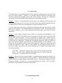
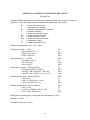
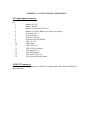
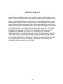
MODEL CR-1A HYGROMETER
OPERATING MANUAL
May 2008
BUCK RESEARCH INSTRUMENTS, LLC
PO Box 19498
Boulder, CO 80308
Copyright 2008. Buck Research Instruments, LLC. All rights reserved.
TABLE OF CONTENTS
1. Introduction .................................................................................................................. 4
1.1 General Description ....................................................................................... 4
1.2 Specifications ................................................................................................. 5
2. Location of Principal Components .............................................................................. 6
2.1 Main Unit ....................................................................................................... 6
3. Installation and Operation ........................................................................................... 8
3.1 Installation ..................................................................................................... 8
3.2 Power-up Procedure ...................................................................................... 8
3.3 Operation ........................................................................................................ 9
3.4 Power-down Procedure ................................................................................ 10
4. Signal Processing ....................................................................................................... 11
4.1 Data Signals ................................................................................................. 11
4.2 Data Reduction Equations ............................................................................ 11
5. Principles of Operation ..............................................................................................
5.1 General .........................................................................................................
5.2 Technical details ..........................................................................................
5.2.1 Sampling System ...........................................................................
5.2.2 Mirror Module ...............................................................................
5.2.3 Optics Module ...............................................................................
5.2.4 Temperature Readout ......................................................................
12
12
12
12
15
15
15
6. Measurement Limitations .......................................................................................... 16
7. Maintenance and Troubleshooting .............................................................................
7.1 Sample line Cleaning ...................................................................................
7.2 Mirror Cleaning ............................................................................................
7.3 Leak Testing .................................................................................................
7.4 Troubleshooting Guide .................................................................................
Appendix 1:
Appendix 2:
Appendix 3:
Appendix 4:
17
17
17
18
19
Humidity Conversion Equations ................................................................ 20
Connector Pin Assignments ....................................................................... 22
Warranty ..................................................................................................... 23
Mirror cleaning procedure……………………………………….…….......24
2
FIGURES
Fig. 1. Main unit............................................................................................................................ 4
Fig. 2. Block diagram, CR-1A chilled mirror hygrometer.......................................................... 13
Fig. 3. Sensor assembly block diagram....................................................................................... 14
3
1. INTRODUCTION
The Model CR-1A Cryogenic Hygrometer is a high performance instrument, capable of fast,
accurate measurements over an extremely wide humidity range. Because these performance
capabilities have not previously been available in a single instrument, the CR-1A represents a
significant advance in the state of the art. The CR-1A differs from the original CR-1 primarily
by having compact size, light weight, and a linear output signal. There is a battery powered
option for portable use for up to 8 hours. There is also an optional version of the CR-1A with
an autofill system that allows for continuous operation when connected to a large LN2 dewar
and provide continuous use for up to a month at a time. The technology incorporated in the CR1A is protected by domestic and foreign patents.
1.1 General Description
The CR-1A is a chilled mirror, condensation type hygrometer. Its high performance is
achieved by cryogenically cooling a mirror, using liquid nitrogen or other cryogen, and holding
it at the frost point by a heater/control system. Optical detectors sense condensate on mirror,
and a thermistor imbedded in the mirror is used to determine mirror temperature--the dew or
frost point. Since operation of the CR-1A is based on a fundamental property of water vapor
(dew/frost point), it is intrinsically capable of long-term accuracy and stability.
The CR-1A features an autobalancing function that automatically adjusts for mirror
contamination. To keep a constant layer of dew or frost on the mirror, the reflectivity of the
mirror must be measured when the mirror is completely cleared of condensation and when it is
completely obscured by condensation. Once this is done, 20% of this span is calculated and set
to be the control point. This is achieved by heating the mirror to a high enough temperature to
remove condensation, then turning on and off the LED that shines on the mirror. If
contamination ever gets to be enough that the control point cannot be achieved, another balance
function will be initiated and the control point reset. Once the contamination becomes too
great, an LED is illuminated to indicate that the mirror needs to be cleaned.
The CR-1A is microcontroller-based. The microcontroller uses flash memory that is fieldprogrammable and updateable. If this is required, please contact Buck Research Instruments,
LLC for instructions.
The instrument consists of a sensor assembly mounted on a cryogen Dewar, and electronics to
provide power, control, displays, and analog output signals, all contained in a single chassis.
Great care is taken to ensure maximum reliability and safety of operation, including coolant
overpressure protection and dual protection against overheating of the mirror assembly.
The components of the CR-1A are:
Main assembly, containing dewar, sensor, and electronics
Power cable and 24 VDC brick power supply
Service kit with spare o-rings and gaskets
NISSAN STAINLESS thermos for filling dewar
Null modem cable and connector for J2
Operating manual
4
1.2 Specifications, Model CR-1A Cryocooled Hygrometer
Measurement range
Moisture concentration
Dew/Frost point
0.01 to 27,000 ppmv at SP
-120 oC to +30 oC
Dew/Frost point reading accuracy
+ 0.15 oC
Response time
10-30 sec typical
Nominal operating range
Ambient Temperature
Gas Pressure
Flow rate of sample
-40 to +40 oC
0 to 150 psia (0-10 bar)
.5 - 2 liters/minute
Construction
316L stainless steel
Dewar capacity
Operating time per filling
With optional autofill system
Loss rate when not in use
0.6 liter
6.0 - 10.0 hours
1 month
about 0.6 L/day*
Input voltage
100-240 VAC, 50-60 Hz (brick supply)
4500 mAh NiMH battery
(optional)
Power consumption
25 watts maximum
Weight
12.5 lbs (5.7 kg) including batteries
Dimensions (chassis)
8" W x 12" D x 11" H (20 x 30 x 27.5 cm)
* This
is just for reference. DO NOT leave LN2 in the dewar when the CR-1A is off.
Note: These are approximate specifications. Exact performance will vary depending
on installation and operating environment.
5
2. LOCATION OF PRINCIPAL COMPONENTS
2.1 Main Unit (Figure 1)
Front
Balance Switch
Display
Heat/Cool Switch
Power Switch
Rebalance LED
Service Mirror LED
Top
Black plastic dewar
lid with built-in
brass pressure relief
valve
Dewar top with
built-in funnel
Back
RS-232 Connector
Dewar Plug
Signal Output, J2
Power Connector
Sample chamber,
pressure connection
and outlet
Inlet to Sample
Chamber
Fig. 1. Main unit
6
A. BALANCE SWITCH (momentary). Depress for 5 seconds to initiate a balance cycle.
This will heat the mirror up to +30° C to clear off condensation and rebalance the optics
circuit.
B. HEAT/COOL SWITCH (momentary). Provides additional heat to partially clear the
mirror of condensate, or full cooling to allow additional frost to collect on the mirror.
Also used to speed initial layer formation. See section 3.2.
C. REBALANCE LED. Lights during balance cycle. Also stays lit after balance cycle if
there is a small amount of contamination on the mirror.
D. DISPLAY. Backlit LCD display that displays H2O concentration, mirror temperature
(Mirror T or D/F Point when dew or frost point acquired), pressure (in millibar) and
balance (± 200 when dew/frost point acquired). Displays internal main PCB
temperature when HEAT/COOL switch depressed.
E. POWER SWITCH
F. SERVICE MIRROR LED. Flashes when there is too much contamination on mirror.
Mirror must be cleaned to restore normal operation of instrument.
G. OUTLET AND (Optional) PRESSURE TRANSDUCER. Connect sampling pump or
vent here. 1/8” tubing goes to pressure transducer inside instrument.
H. OPTICS BLOCK AND CABLE. Contains LED and detector that looks at mirror
through lens. Loosen 2 screws inside 2 holes in top of cap to remove optics block to
clean mirror. Screws stay captive inside cap. Cable is also captive.
I. POWER CONNECTOR. Connect included power supply to this connector.
J. RS-232. Connect to data acquisition system or PC running Hyperterminal .
K. INLET. Connect tubing to inlet.
L. SIGNAL OUTPUT 0-10 V and 4-20 mA outputs for various signals. See section 4.
M. DEWAR PLUG. Use dewar plug operator with this plug if the vacuum needs to be
recharged. (If the mirror will no longer make -120 ºC the vacuum may need to be
recharged.) Please contact Buck Research Instruments, LLC for instructions on how to
do this.
7
3. INSTALLATION AND OPERATION
3.1 Installation
1. Inspect the instrument for mechanical or other damage.
2. Connect the inlet and outlet gas flow lines to the sensor assembly. Make sure there is some
flexibility in both inlet and outlet lines to avoid stress and possible damage to the CR-4.
NOTE: do not over tighten Swagelok-type fittings. Over tightening can destroy their
sealing ability. Adjust the flow rate of the gas so that it is less than 2 lpm (4 scf/h).
3. Initially and as often thereafter as necessary, check that all electrical and mechanical
connections are secure. It may be advisable to test for leaks using one of the methods in
Section 7. This is especially important when operating the instrument in a humidity
environment that is very different from that of the sampled air.
3.2 Power-up Procedure
1. Connect the external power supply to the power connector on the back of the instrument.
Flip the power switch to the ON position. If unit is supplied with internal batteries, external
power supply connection is not required. However, if “LOW BATTERY” Is displayed in
place of BALANCE = on the display after the balance cycle in step 2 below completes,
reconnect the power supply as the batteries are almost completely discharged and the
instrument will soon shut down.
2. After initialization of the electronics, a balance cycle will be initiated. The Rebalance LED
will light and the display will show an increasing mirror temperature until +30°C is
reached.
3. Fill Dewar with liquid nitrogen. (Please see separate instructions in the appendix if you
have the autofill system). First, unscrew the black plastic threaded lid that contains a brass
pressure relief valve. This will expose a funnel-shaped lip on the top of the dewar. Use the
included NISSAN STAINLESS thermos to fill the dewar. If you put the lip of the thermos
to the lip of the dewar lid and tilt slightly, the dewar should fill the fastest possible way. If
you tilt too much, there will be splatter of the LN2. You will need to fill the thermos
between 2 and 2 1/2times to fill the dewar. When you can see LN2 bubbling at the top of
the dewar where the stainless steel bellows is, you are done. Be careful not to overfill. Wait
until there is no more boiloff before you screw the lid back on. This should take no more
than 5-10 minutes.
CAUTION: Use extreme care with liquid nitrogen. Liquid nitrogen has a sea
level boiling point of -196 oC, with a large expansion ratio in volume from
liquid to gas: approximately 700 to 1. Very brief contact with fluids at
cryogenic temperatures can cause injury similar to thermal burns. The eyes
are especially vulnerable to this type of exposure. Use a proper transfer
container to transfer cryogen to the instrument, and avoid direct contact with
8
any part of body or clothing, wearing safety glasses and clothing as necessary
(Caution: fabric gloves can "hold" the liquid nitrogen and must be avoided.)
Avoid venting to a confined small space, possibly displacing the air and
causing oxygen deprivation.
4. Then, wait for the instrument to stabilize at the operating point. The mirror temperature
will decrease until the Balance value gets close to 0. Then the mirror temperature will
increase until the Balance voltage stays between ± 200, at which point the display changes
from Mirror T to D/F Point and H2O Conc. Will change from XXX.X to a value.
5. The instrument is now ready for use. Connect up the flow of gas. Keep the flow to 2 slpm
or less to improve stability and keep the heat load on the mirror to a minimum. The higher
the flow rate, the faster the LN2 will boil off.
NOTE: It is always advisable to start measuring at relatively high humidity values
(above -20oC), to allow easy acquisition of condensation, and then go down in frost
point temperature. If it is necessary to begin operating initially at very low frost
points, acquisition of frost can be speeded up by use of the HEAT/COOL SWITCH
and by spiking the pressure inside the sample chamber. To do this, stop flow through
the sample chamber for no more than 1-2 seconds by putting a finger over the outlet of
tubing connected to the outlet of the sample chamber, or closing a valve downstream
of the outlet of the sample chamber. This will spike the pressure inside the chamber,
causing a large amount of moisture to collect on the mirror. Watch the BALANCE
value on the display. It will go positive. As soon as the value stops increasing depress
the COOL switch and hold it. This will keep the frost layer on the mirror from being
burned off and enable readings within 1 or 2 minutes instead of 10 to 20 minutes.
3.3 Operation
During operation, no special attention is required except for an occasional check of operating
voltages to assure proper function. If possible, keep flow in the range 0.5 - 2 liters/minute
(0.25 – 4 scf/h). At very high dew/frost point temperatures, higher flow may be allowed.
Keep the sample line inlet protected from contamination. This is best achieved by keeping the
sample line closed when not connected to the desired sample gas. WHEN MEASURING
WATER CONCENTRATION IN NATURAL GAS, A GLYCOL-ABSORBING FILTER,
SUCH AS AN A+ GLYSORB FILTER, MUST BE INSTALLED BEFORE THE INLET TO
THE CR-4 OR ERRONEOUS READINGS WILL RESULT.
When making a large downward change in humidity, it is better to make several intermediate
steps rather than one large step, to avoid losing the condensation layer on the mirror. At low
frost point values, always allow time for the moisture levels in the lines and sensing chamber to
equilibrate, and for the D/F point temperature to completely stabilize before taking a reading.
To avoid internal line condensation and resultant erroneous readings, do not allow the inlet
lines to cool below the expected frost point temperature.
9
3.4 Power-down Procedure
1. Watch the display. (For autofill system. See disconnection procedure in appendix.) When
the mirror temperature starts to get warmer than the dew point you expect, this indicates
that there is no more LN2 in the dewar and you can proceed to step 2.
2. Initiate a balance cycle by depressing the BALANCE switch for 5 seconds.
3. Watch the mirror temperature, if the mirror temperature does not go below 0 C, turn power
off. If the mirror temperature goes below 0 C, wait for the mirror temperature to warm up to
0 C before turning off power.
4. Turn off flow of gas to the CR-1A.
5. You can leave the power supply connected to recharge the batteries. HOWEVER, it is not
recommended to leave the external power supply connected for long periods of time, as the
batteries are continually charged and will start to get hot. We recommend disconnecting the
external power supply after 24 hours if the CR-1A is not turned on again and used in that
period of time.
10
4. SIGNAL PROCESSING
4.1 Data Signals
The following analog signals are available at signal connector J2, and vary over the following
ranges:
VDF
PRES
H2O CONC
BAL
VAMB
Mirror temperature (Dew/frost point), 0-10v and 4-20 mA
Chamber pressure, 0-10v and 4-20 mA
lb/MMscf or ppmv, 0-10v and 4-20 mA (optional)
Balance voltage, 0-10v and 4-20 mA
Ambient temperature, 0-10v and 4-20 mA (optional)
The 4-20 mA outputs sink current. Connect up +24 VDC to the 4-20 mA returns, either using
the pins on the connector or from your data acquisition system. The current flowing into the 420 mA returns corresponds with the equations below.
4.2 Data Reduction Equations
VDF: Dew/frost point temperature is determined from VDF by:
Tdf (°C) = [-150 + 20 x VDF(v)].
Tdf (°C) = [-150 + 8 x IDF(ma)].
(0-10V)
(4-20 mA)
(1)
(2)
VAMB: Chamber temperature is determined from VAMB by:
Tamb (°C) = [-100 + 20 x VAMB(v)].
Tamb (°C) = [-100 + 8 x IAMB(ma)].
(0-10V)
(4-20 mA)
(3)
(4)
PRESSURE: Chamber pressure is calculated from the Vpress signal voltage by:
Press = (Vpress – 1.6) * 1.5625
Press = (Ipress – 4) / 1.6
(0 – 10 bar sensor) (/10 for 1 bar sensor)
(0 – 10 bar sensor) (/10 for 1 bar sensor)
(5)
(6)
BALANCE: When balanced, BAL = 5V or 12.5 mA.
H2O CONC: 2- 4 V = 0-1000 ppbv, 4-6 = 0-1000 ppmv, 6-8 V = 0-1000 PPTV.
Conversion to Other Humidity Units To convert dew/frost point readings to other humidity
units, refer to Appendix 1.
11
5. PRINCIPLES OF OPERATION
5.1 General
The CR-1A is a chilled-mirror, condensation-type hygrometer, consisting of the following
principle components: a rhodium plated copper mirror with an attached stem, an associated
temperature sensor and heating coil, a liquid nitrogen system for cooling the mirror, an optical
system for sensing condensate (mirror reflectance), and control circuitry for controlling mirror
temperature via the heating coil.
Operation is based on maintaining equilibrium vapor pressure over a water or ice surface on the
mirror. Above the equilibrium temperature, mass transport is away from the surface, and
below the equilibrium temperature it is onto the surface. When the surface is just at the
dew/frost point temperature, the mass of condensate on the surface remains constant.
As is the case with conventional cooled dew-point devices, the mirror, optics and electrical
circuit make up a thermo-optical servo system which operates to maintain a constant layer of
condensate. When condensate is thus equilibrated, mirror temperature is then at the dew/frost
point, which is sensed by the imbedded temperature sensor. Since the dew/frost point
temperature is a fundamental measure of humidity, the CR-1A is intrinsically capable of long
term accuracy and stability.
The development of this hygrometer follows the original work of H.J. Mastenbrook at NRL.
His work was adapted by the NOAA Geophysical Monitoring for Climatic Change (GMCC)
program for balloon-borne stratospheric water vapor measurements. Buck Research has
extensively redesigned and reconfigured the instrument for a broader range of measurements
and applications, incorporating proprietary new technical innovations in the process.
5.2 Technical details
A block diagram of the cryocooled hygrometer is given in Figure 2 and the sensor assembly is
diagrammed in Figure 3.
5.2.1 Sampling system
The gas to be measured (sample gas) is brought to the sensing chamber through an inlet system
and allowed to flow across the mirror surface in the sensor chamber. At the exit of the sensor
chamber, the sample gas flows by a pressure gauge and is then returned to the original gas
stream or exhausted as desired.
12
Fig. 2. Block diagram, CR-1A chilled mirror hygrometer
13
Fig. 3. Sensor assembly block diagram
14
The sampling system must be carefully sealed to prevent room or cabin air from contaminating
the measurements. Stainless steel materials must be used throughout the inlet portion to
minimize outgassing during low humidity sampling.
5.2.2 Mirror Module
The mirror assembly consists of a mirror, a mirror support, and the RTD, heater, and sensor
that are attached to the mirror. A small ultra-stable RTD is installed beneath the mirror face to
measure the dew/frost point temperature. Heating is provided by a resistive heater coil wound
around the mirror stem.
5.2.3 Optics Module
The mirror surface is maintained continuously and automatically at the frost-point temperature
by an electro-optical control system. This system measures the quantity of light specularly
reflected from the mirror condensate and maintains a constant reflectance at the mirror surface,
thus providing the condensate equilibrium for the frost-point temperature.
The optics module consists of a photodiode pair and a light emitting diode (LED). One
photodiode maintains constant LED intensity; the other photodiode provides a current output
that is proportional to the light reflected from the mirror. The bias circuit is set so that when
the proper condensation layer is on the mirror, about 80% of the light emitted by the LED is
received at the detector.
.
5.2.4 RTD Readout
For obtaining the dew or frost point temperature from the temperature senor, three readouts are
provided: VDF signal voltage, RS-232 output and a direct temperature indication on the
display. All are accurate within ±0.15oC throughout the measurement range.
15
6. MEASUREMENT LIMITATIONS
Under field operations, measurement errors can arise from a number of causes. Any deviation
of the mirror temperature from the frost-point temperature will of course cause error.
Perhaps the most common error source is from outside air leaking into the hygrometer
sampling system. Therefore, it is important that the instrument be leak tested periodically, and
with each relocation of the instrument, especially if components of the instrument have been
exchanged or serviced.
Long exposure of the sampling system to high humidities, or condensation of water (which
occurs if cold surfaces are exposed to ambient air which has a higher dew point than the
temperature of the surfaces) causes temporarily high readings until the walls have completely
outgassed. The lines may take a very long time to dry enough to allow accurate readings when
measuring frost points below -50oC. Any hygroscopic material in the lines or chamber, such as
dust, further lengthens this time. It is therefore advised to keep the lines clean and dry.
Calibration of the mirror temperature sensor and associated electronics is required to accurately
determine dew/frost point temperature. Buck Research Instruments has done this. Once
calibrated, the temperature sensor has been found to exhibit no measurable drift, even after
years of use. Low drift components are used throughout the temperature sensing circuit to
ensure long-term accuracy. However, recertification and recalibration is recommended yearly
to ensure proper operation.
Errors can arise from failure to correct for differences between chamber pressure and ambient
values. This is only important if you are measuring ambient dew/frost point and not H2O
concentration.
The system must be allowed to fully equilibrate before accurate readings can be obtained.
When measuring very low frost points, equilibration can take much longer.
Within twenty degrees below freezing, the existence of supercooled water on the mirror can
cause the temperature to read low, as the instrument is measuring dew point. Eventually the
dew will turn to frost. To speed this up, press the COOL switch and allow the mirror to cool 510 degrees below the dew point reading, then release COOL switch. This will convert the dew
to frost, as long as the mirror temperature does not go above 0° C after COOL switch is
released
Contamination of the mirror by salt or other electrolytes can vary the relationship
between vapor pressure and dew/frost point (Raoult error).
Other chemical
contamination may cause similar error. This is particularly relevant when measuring in
natural gas, as glycols contained within it can condense out on the mirror. This is why a
glycol-absorbing filter must be used when measuring natural gas.
16
7. MAINTENANCE AND TROUBLESHOOTING
The following maintenance items should receive attention as required:
1. Cleaning of sample lines, depending on use (Sect. 7.1).
1. Mirror check and cleaning (Sect. 7.2).
2. Leak checking (Sect. 7.3)
7.1 Sample line Cleaning
To keep sample lines clean, thus improving response at very low humidities, wash with water
or acetone and blow dry with a mild pressure from a dry air or nitrogen source. It may be
desirable to heat the lines for a few moments to drive off residual water.
7.2 Mirror cleaning
The mirror should be cleaned when the Check Mirror LED is flashing.
1. Make certain mirror is at or near the room temperature and power has been shut off.
There are 2 holes in the flat part of the optics block. Insert hex ball driver into holes and
loosen each screw. The screws will remain captive inside. Once screws are loose,
remove optics block. It will be held by the cable coming out of it, which is not
removable. The mirror is now exposed and can be cleaned.
2. See Appendix 4 for detailed procedure.
3.
If necessary, repeat process. If contamination persists, clean again with acetone,
followed by water, using a small amount. Never use alcohol in the sensing chamber, as
this affects the hygroscopic properties of the mirror surface for some period of time. (In
the absence of acetone, distilled water alone or used after acetone or MEK can be
effective.)
CAUTION: The mirror surface has a coating that scratches easily. However,
moderate scratching does not prevent normal operation. Use only soft flexible
cotton swabs to clean the mirror. Apply minimal pressure
4. Turn instrument power on and wait and see if Service Mirror LED and Rebalance LEDs
turn off. If either or both LEDs stay lit, try cleaning the mirror again. Make sure the
mirror is completely dry before turning power on.
5. If the Service Mirror LED cannot be turned off by cleaning the mirror, remove the optics
block and clean the lens and entire sample chamber.
17
7.3 Leak Testing
The introduction of even small amounts of room air into the sampling system will cause errors
in low frost point readings. Therefore, it is desirable that leak testing be performed on the
instrument package and sampling system after initial assembly, and after any maintenance
activity that involves disassembly of the instrument or interconnecting tubing.
Method 1. Connect a vacuum pump and vacuum gauge to the sampling system inlet port, and
close or cap the outlet port (or vice versa). Evacuate down to the minimum attainable pressure.
A reading of 100 microns Hg or less indicates the system is adequately sealed.
To locate a leak, place a few drops of alcohol on each tubing connection and watch the vacuum
gauge pressure reading. If the reading abruptly increases, there is a leak. Allow some time for
the vacuum readings to recover after each upscale deflection before proceeding to the next
connection.
Method 2. If the vacuum pumping system is unable to evacuate the inlet plumbing to a level
that will produce an on-scale reading on the vacuum gauge, disconnect the vacuum pump from
the gas inlet port and replace it with a low-pressure air supply with a needle valve for
regulation. Slowly pressurize the gas inlet tubing, being careful to limit the pressure applied to
no more than two atmospheres. Dampen the inlet tubing connections with soap solution or
other leak detection solution, and watch for air bubbles forming at each connection. The
presence of any air bubbles indicates a leak at the connection. Repair any connections found
leaking and recheck for leaks. When no more bubbles can be found, disconnect the lowpressure air supply and reconnect the vacuum pumping system. Repeat the preceding vacuum
leak testing procedure.
CAUTION: Overpressure within the above limits will not damage the pressure
sensor. However, slight calibration adjustments may be necessary after any
overpressure. Overpressure limit: 100% of span.
Method 3. Plug one end of the sensing chamber. Attach an ordinary pump with a shutoff valve
to the other end. Lower the pressure as much as possible. Close the shutoff valve and monitor
pressure inside the sensing chamber to determine leak rate. With proper sealing, the pressure
change rate should be less than 0.2 % of pressure differential per minute. Leaks can then be
located by overpressuring the instrument as in Method 2.
7.4 Troubleshooting Guide
18
Display shows Mirror needs cleaning. Service Mirror LED blinking:
1. Mirror needs cleaning. Clean mirror
2. Optics cable is disconnected. Reconnect optics cable.
Rebalance LED stays lit after balance cycle finishes:
1. Mirror starting to get contaminated. CR-1A will continue to function normally, but
be prepared to clean mirror soon.
Oscillation of output :
1. Reduce sample flow until oscillation stops, then gradually increase flow again.
2. Turn instrument off, allow to warm up, and clean mirror.
3. If oscillation is slow (10-20 sec period) and most pronounced in the region -30 to 50oC, cavity resonance (interaction with contaminants in the chamber) may be
occurring. Clean sensing chamber with the CR-1A cleaning fluid supplied.
19
APPENDIX 1: HUMIDITY CONVERSION EQUATIONS
(Revised 7/96)
Computer-efficient algorithms for converting among several humidity units, as used in HCON, are
given here. They utilize vapor pressure formulations developed by A. Buck (1981).
DP
e
es
P
r
RH
rho
rhos
T
Tk
= dew or frost point in deg C
= vapor pressure in millibars
= saturation vapor pressure in millibars
= pressure in millibars
= mixing ratio by weight in ppm
= relative humidity in percent
= absolute humidity in g/m3
= absolute humidity at saturation
= temperature in deg C
= absolute temperature in K
Saturation vapor pressure (es) = f1(T) = e/RH
Dew/frost point (DP) = f2(e)
= f2[r x P/(622 x 103 + r]
= f2(RH x f1(T)/100)
= f2(rho x Tk/216.7)
(e)
(r)
(RH)
(rho)
Vapor pressure (e)
= f1(DP)
= r x P/(622 x 103 + r)
= RH x f1(T)/100
= rho x Tk/216.7
(DP)
(r)
(RH)
(rho)
Mixing ratio (r), ppmw = 622x103 x e/(P-e)
= 622x103 x f1(DP)/[P - f1(DP)]
= 622x103 x RH x es/(100 x P - RH x es)
= 622x103 x rho x Tk/(216.7 x P - rho x Tk)
(e)
(DP)
(RH)
(rho)
Relative humidity (RH) = 100 x f1(DP)/f1(T)
= 100 x e/es
= 100 x r x P/[(622x103 + r) x es]
= 100 x rho x Tk/(216.7 x es)
(DP)
(e)
(r)
(rho)
Absolute humidity (rho)= 216.7 x f1(DP)/Tk
= 216.7 x e/Tk
= 0.2167 x r x P/[(622 + .001 x r) x Tk]
= 216.7 x RH x es/(100 x Tk)
(DP)
(e)
(r)
(RH)
mixing ratio by volume (ppmv) = mixing ratio by weight (ppmw) x 1.6077
grains/lb = r x 0.007
Precipitable cm per km = rho/10
20
- 21 -
NOTE 1: f1(DP) and f2(e) are variations on vapor pressure formulations found in Buck, A: J Appl
Met 20, pp 1527-1532 (1981). They are given by:
e vs. DP or es vs. T:
f1(DP) = EF x aw x exp [(bw - DP/dw) x DP/(DP + cw)] (over water)
= EF x ai x exp [(bi - DP/di) x DP/(DP + ci)] (over ice)
DP vs. e or T vs. es:
f2(e) = dw/2 x [bw - s - ((bw - s)2 - 4 cw x s/dw)1/2]
= di/2 x [bi - s - ((bi - s)2 - 4 ci x s/di)1/2]
(over water)
(over ice)
where:
aw = 6.1121
bw = 18.678
cw = 257.14
dw = 234.5
ai = 6.1115
bi = 23.036
ci = 279.82
di = 333.7
s = ln (e/EF) - ln (aw or ai)
2
EFw = 1 + 10-4 [7.2 + P (0.0320 + 5.9 x 10⁻⁶ T )],
2
EFi = 1 + 10-4 [2.2 + P (0.0383 + 6.4 x 10⁻⁶ T )],
where P is in kPa and T is in oC.
NOTE 2: RH is defined here using es with respect to ice below freezing. However, RH is also
frequently defined using es with respect to water, even below freezing.
NOTE 3: These conversions are intended for use with moist air rather than pure water vapor. They
therefore include EF, the enhancement factor, which corrects for the slight departure of the behavior
of water in air from that of a pure gas.
NOTE 4: The definitions f1 and f2 for ice agree with an extrapolation of NBS values down to -120
deg C, within 0.5%.
21
APPENDIX 2: CONNECTOR PIN ASSIGNMENTS
J2 16-pin Signal connector
Pin
1
2
3
4
5
6
7
8
9
10
11
12
13
14
15
16
Balance (0-10 V)
Balance Return
Balance (4-20 mA) (DC Power)
Balance (4-20 mA) Return (for self-powered loops)
Pressure (0-10 V)
Pressure Return
Pressure (4-20 mA)
Pressure (4-20 mA) Return
VDF (0-10 V)
VDF Return
VDF (4-20 mA)
VDF (4-20 mA) Return
Dew Point (0-5 V)
Dew Point Return
Dew Point (4-20 mA)
Dew Point (4-20 mA) Return
J4 RS-232 connector
9600 Baud, 8-N-1. Flow control set to NONE. Use null modem cable with Female/Female
ends.(Included)
APPENDIX 3:WARRANTY
Manufacturer warrants that the items delivered shall be free from defects (latent and patent) in
material and workmanship for a period of one year after acceptance of the specific goods by
Buyer. The Buyer’s sole and exclusive remedy under this warranty shall be limited to repair or
replacement. Defective goods must be returned to the Manufacturer promptly after the
discovery of any defect within the above referenced one-year period. Transportation expenses
to return unit to Manufacturer shall be borne by the Buyer. Return shipping to Buyer shall be
borne by Manufacturer for valid warranty claims. This warranty shall become inapplicable in
instances where the items have been misused or otherwise subjected to negligence by the Buyer
NOTWITHSTANDING ANY OTHER PROVISION OF THIS CONTRACT, NO OTHER
WARRANTIES WHETHER STATUTORY OR ARISING BY OPERATION OF LAW,
EXPRESSED OR IMPLIED, INCLUDING BUT NOT LIMITED TO THOSE OF
MERCHANTABILITY OR FITNESS FOR PARTICULAR PURPOSE, SHALL APPLY TO
THE GOODS OR SERVICES PROVIDED HEREUNDER, OTHER THAN THE REPAIR
AND REPLACEMENT WARRANTY ABOVE . SELLER SHALL IN NO EVENT BE
LIABLE TO BUYER OR ANY THIRD PARTY FOR ANY DAMAGE, INJURY OR LOSS,
INCLUDING LOSS OF USE OR ANY DIRECT OR INDIRECT INCEDENTAL OR
CONSEQUENTIAL DAMAGES OF ANY KIND.
23
Appendix 4. CR-1A Mirror Cleaning Procedure
Removal
Insert 5/64” ball driver through the 2 top holes of the optics cap to find the #2-56 socket head screws inside.
Loosen those screws to remove the optics block. Using the 9/64” ball driver, completely remove all 6 #8-32 socket
head screws from the lens holder. Be careful when removing the last screw as there is a nickel gasket (or rubber oring) in between the lens holder and the top of the sample chamber. Also, the lens sticks out of the lens holder, so
do not place the lens holder lens-side down. Always have the lens facing you when setting the lens holder down.
You should be able to reuse the gasket about 10 times, and if you are lucky and do not touch it, the gasket will
stay in place.
Cleaning the Mirror
Once you have access to the mirror, dip a cotton tipped applicator in acetone and clean the mirror gently. Use each
applicator only once. After the mirror has been cleaned with acetone, wipe the mirror with a dry applicator. Then
dip another applicator in water and wipe the mirror off again. Finally, wipe the mirror off with a dry applicator to
complete the cleaning process.
Replacement
Now, put the lens holder back on the sample chamber.Use the index marks to get the correct alignment. Start
middle 2 screws that are 180 degrees apart. Leave a ¼” gap for the gasket if the gasket has separated from the
sample chamber. Next, insert the bottom 2 socket head screws to prevent the gasket from falling through. Drop the
gasket into the ¼” gap making sure that it is in the correct position before tightening the screws any further. If the
gasket is sitting too low a small metal strip or a metal ruler can be used to lift the gasket ( or optional viton o-ring)
back into place. Tighten the captive screws first, using the 9/64” ball driver. Alternate back and forth between both
screws. Tighten the other 4 socket head screws making sure that there is no gap between the sample chamber and
the lens holder. Do not use excessive force when tightening the screws. Do a leak check now. If there is a leak,
alternate tightening the 6 screws by tightening the screw 180 degrees from the one just tightened, then move to the
next screw and do the same thing. (If you number the screws 1-6 where 1 is on the top, go 1-4-2-5-3-6.) You may
need to use a right-angle 9/64” hex key to get more torque if the ball driver will not tighten the screws any more.
Lastly, put the optics block and cap back on using the 5/64’ ball driver. Insert the ball driver into the 2 holes on
top of the optics cap to find the socket head screws in the optics block. Make sure that there is no gap between the
optics block and the lens holder.
24
Addendum:
Key stroke input to RS-232
c
C
p
P
d
D
i
I
decrease the contrast of the LCD display by 2%
increase the contrast of the LCD display by 2%
decrease the proportional gain coefficient by 2/3rds
increase the proportional gain coefficient by 50%
decrease the derivative gain coefficient by 2/3rds
increase the derivative gain coefficient by 50%
decrease the integrator time constant coefficient by 2/3rds
increase the integrator time constant coefficient by 50%
Each repeated key press is progressive. For example, 5 C presses will increase the
contrast by 10%. 5 p presses will decrease the gain by about 87%
R
B
resets all coefficients and contrast to original values
initiates a balance routine
25