1
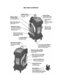
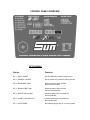
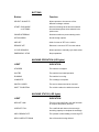
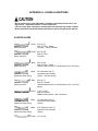
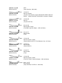
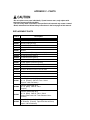
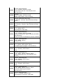
TABLE OF CONTENTS
(Page numbers will be assigned when inserted into template.)
• INTRODUCTION
• SAFETY INFORMATION
- Important Safety Notices
- Important Safety Instructions
• SYSTEM FEATURES AND SPECIFICATIONS
- Features
- Dimensions and Technical Specifications
- Machine Overview
- Control Panel Overview
- Special Functions
• OPERATING PROCEDURES
- Suggested Additional Tools
- Transmission Fluid Exchange
- Power Steering Fluid Exchange
• TROUBLESHOOTING AND ADDITIONAL HELP
- Common Problems/Solutions
- Customer Service Contact Info
• APPENDIX A - Hoses & Adapters
- Adapter Hoses
- Adapters
• APPENDIX B - Maintenance
- Maintenance Procedures
• APPENDIX C - Parts
- Replacement Parts
- Ordering Replacement Parts
• WARRANTY INFORMATION
INTRODUCTION
Congratulations on the purchase of your SUN MFX Xtreme transmission fluid and power steering
fluid exchanging machine!
Simply put, this machine is the cleanest, safest, easiest, fastest, most thorough, and most costefficient method of fluid exchange ever devised. Suddenly, regular automatic transmission and
power steering maintenance become a more realistic proposition. Transmission and power
steering fluid exchanging are cleaner and neater than ever!
Transmission Fluid Exchange:
To attain the highest level of protection for internal transmission components and increase the life
span of your transmission to the maximum, it is recommended that the transmission’s lubrication
system is serviced every 15,000 miles (or according to the vehicle owner’s manual). The SUN
MFX Xtreme exchanges virtually all of your used transmission fluid to new, without requiring you
to drop the transmission pan. There is no spillage, and no mess.
Power Steering Fluid Exchange:
Service neglect leads to power steering system complaints including poor handling, hard or
sluggish steering, and objectionable noise. Historically, power steering system fluid service has
been neglected, often due to the lack of a convenient method for providing such flush or fluid
exchange services. Previous methods for flushing the power steering system or replacing the
power steering fluid were time consuming and often inefficient or incomplete. Now, it’s easier than
ever to replace up to 95% of the old power steering fluid in less than 8 minutes!
• The MFX Xtreme can be used practically anywhere – and with almost any vehicle.
• It is compact, mobile, and self-contained.
• It operates off the 12-volt battery of the vehicle being serviced.
• You do not need a pit, lift, or ramp.
• The MFX Xtreme hooks up directly to one of the vehicle’s transmission cooler lines for a
transmission fluid exchange.
• The ATF fluid exchange, from setup to finish, typically takes 15 minutes or less!
No wonder an ATF exchange is the most requested method of preventative automatic
transmission maintenance today. Now you have the option of a power fluid exchange as well…
Both in one machine!
Please take time to read through this manual to familiarize yourself with the SUN MFX
Xtreme before performing your first ATF or PSX exchange.
SAFETY INFORMATION
Important Safety Notice
For your safety, read this manual thoroughly before operating your MFX Xtreme unit.
Your MFX Xtreme unit is intended for use by properly trained, skilled professional automotive
technicians. The safety messages presented below and throughout this user’s manual are
reminders to the operator to exercise care when using this unit.
Before using your MFX Xtreme unit, always refer to and follow the safety messages and
applicable service procedures provided by the manufacturer of the vehicle being serviced.
Read All Instructions
Read, understand and follow all safety messages and instructions in this manual. Safety
messages in this section of the manual contain a signal word with a three-part message and, in
some instances, an icon. The signal word indicates the level of the hazard in a situation:
Indicates an imminently hazardous situation which, if not avoided,
will result in death or serious injury to the operator or to bystanders.
Indicates a potentially hazardous situation which, if not avoided,
could result in death or serious injury to the operator or to bystanders.
Indicates a potentially hazardous situation which, if not avoided,
may result in moderate or minor injury to the operator or to bystanders.
Indicates a situation which, if not avoided, may result in damage
to the MFX machine or the vehicle being serviced.
Safety messages in this section contain three different type styles:
• Normal type states the hazard.
• Bold type states how to avoid the hazard.
• Italic type states the possible consequences of not avoiding the hazard.
An icon, when present, gives a graphical description of the potential hazard.
IMPORTANT SAFETY INSTRUCTIONS
Products may have inherent risk to the user.
• Read, understand and follow all safety messages in this manual before operating the
SUN MFX Xtreme.
Improper use may result in injury.
Engine systems can malfunction expelling fuel, oil vapors, hot steam, hot toxic exhaust gases and
other debris.
• Wear safety goggles and protective clothing, user and bystander.
Engine systems that fail can cause serious injury.
Risk of expelling pressurized fluids.
• Wear safety goggles and protective clothing, user and bystander.
• Keep the service hoses away from hot or moving engine parts. Hoses can split or burst
causing fluid to be expelled.
• Tighten all connections properly. Insufficient or excessive torque can result in fluid
leakage.
• Avoid contact with automatic transmission or power steering fluid.
• Treatment methods are as follows:
Eyes: Flush eyes with plenty of water.
Skin: Wash with soap and water.
Inhalation: Move to uncontaminated area.
Ingestion: If large amount, get medical attention.
If any irritation persists, get medical attention.
• Dispose of used fluid according to environmental laws and regulations.
Although automatic transmission and power steering fluid pose no significant health hazards,
some individuals may experience adverse reactions upon contact. Pressurized fluid can cause
serious injury.
Engine exhaust contains toxic gases.
• Vent vehicle’s exhaust away from work area.
• Do not breathe exhaust.
Exhaust gases can cause injury or death.
Risk of unexpected vehicle movement.
• Block drive wheels before starting vehicle’s engine to begin an exchange.
• Unless instructed otherwise, set parking brake and put gear selector in park.
• Do not leave a running vehicle unattended.
A moving vehicle can cause injury.
Engine has moving parts. Risk of entanglement.
• Do not place tools on fenders or other places in engine compartment.
• Keep yourself, clothing, battery cables and service hoses clear of moving parts such as
fan blades, belts and pulleys.
Contact with moving parts can cause injury.
Risk of fire or explosion.
• Do not operate the MFX Xtreme in the vicinity of open containers of flammable liquids
such as gasoline.
• Keep hoses and jumper cables away from heat sources and sharp edges.
• Do not operate equipment with damaged cords or hoses until they have been examined
by a qualified serviceman.
Fire or explosion can cause injury.
Risk of fire or explosion. Gases produced by a battery are highly explosive.
• Wear safety goggles and protective clothing, user and bystander.
• This machine is equipped to operate on 12-volt DC power only. A power source greater
than this can result in serious injury to the user as well as damage to the machine.
• Do not smoke, place metal tools on battery or allow a spark or flame in vicinity of battery.
• Clean battery terminals before hooking the machine’s battery clips to them. During
cleaning, keep airborne corrosion from eyes, nose and mouth.
• Be sure both battery cables are tightly connected to the battery terminals as instructed
before proceeding with a fluid exchange.
• Never remove battery cables from the battery terminals while the machine is operating.
Only use the “EMERGENCY STOP” button located on the control panel to stop an
exchange.
Battery explosion can cause injury.
Battery acid is a highly corrosive sulfuric acid.
• Wear safety goggles and protective gloves, user and bystander.
• Have plenty of fresh water and soap nearby. If battery acid contacts skin, clothing, or
eyes, flush exposed area with soap and water for 10 minutes.
• While cleaning battery’s terminals, keep airborne corrosion from eyes, nose and mouth.
• Do not touch eyes while working near battery.
Battery acid can burn eyes and skin.
Risk of burns.
• Wear gloves when working near hot engine components.
• Do not touch hot exhaust systems, manifolds, engines, radiators, etc.
• The automatic transmission fluid coming from the vehicle along with some of the
machine’s components that the fluid comes into direct contact with (i.e. external: hoses
and quick-disconnect fittings; internal: hoses and all fittings) may reach temperatures
uncomfortable to the touch. Exercise caution in avoiding contact with these items.
Hot components can cause injury or discomfort.
Ratchet mechanisms and tools may slip or break if dirty. Mismatched or partially worn parts can
cause ratchet or any tool to slip or break.
• Frequently inspect and clean any tools used, and lubricate all non-sealed ratchet
mechanisms with light oil.
• Do not replace worn parts individually. If adapter hose fittings become worn, see
“Appendix C – Replacement Parts” to order new hoses.
• The use of any other accessories not specified in this manual may create a hazard.
Tools that slip or break can cause injury.
Risk of injury or equipment damage.
• This equipment should be operated by qualified personnel only.
• The SUN MFX Xtreme is fully automatic. Refer to your control panel at all times.
• Use this equipment only as described in this manual. Use only the manufacturer’s
recommended attachments.
• Connect battery cables to a 12-volt power source only (i.e. vehicle’s battery).
• Always unplug the machine from its power source when not in use.
• Loop the power cord loosely in its proper location when machine is not in use.
• Do not operate equipment with a damaged battery cables or hoses, or if the equipment
has been dropped or damaged, until it has been examined by a qualified service
representative.
• Care should be taken to arrange the battery cables and service hoses so that they will
not be tripped over or pulled.
• Never pull on the power cables or service hoses to transport the MFX Xtreme. Damage
may occur to these components, or machine may tip over.
• Servicing, transporting, or storing this machine in an attitude other than the normal
operating position can result in fluid spillage and/or component damage.
• Keep area of operation clear of unnecessary tools and equipment.
• Utilize recessed tool storage areas on the top of the machine.
• Never leave the machine running unattended.
• The MFX Xtreme is not designed for any other purpose than the exchanging of automatic
transmission and power steering fluid.
• Periodically clean the machine by wiping down with a clean, soft, dry cloth.
Operation of your MFX Xtreme unit by anyone other than qualified personnel may result in injury
or damage to equipment.
SAVE AND FOLLOW THESE INSTRUCTIONS.
SYSTEM FEATURES AND SPECIFICATIONS
FEATURES
Cabinet Features
• Durable roto-cast polyethylene body and tanks
• Integral performance designed hose and tool compartment with drain orifice
• 5” locking caster wheels – very maneuverable
• Ergonomically correct working height
• Large diameter fill hole
• Easy access service panel
Electronic Features
• Drain used fluid tank (no need to tip machine upside-down)
• Drain new fluid tank
• Add new fluid to transmission in .2 qt. increments
• Remove fluid from transmission in .2 qt. increments
• Select 4, 12, 16 or 20 qt. exchange volume
• Accurate sensor technology (+/- 5%)
• 10 micron absolute fluid filters
• Cycle valves feature allows you to electronically clean out valves
• Totalize check (indicates lifetime use)
• Interactive options menu:
- “Auto Prime” feature automatically primes the system
- Indicate new fluid volume
- Indicate used fluid capacity
Power Steering Fluid Exchange Unit
• Remote pendant for ease of operation
• Compartment for new fluid bottle
• Drains directly to waste tank
DIMENSIONS AND TECHNICAL SPECIFICATIONS
Cabinet:
Roto-cast molded polyethylene
Fluid Tanks:
24-Quart New Fluid Tank
24-Quart Used Fluid Tank
Dimensions:
39" Tall
25" Deep
17" Wide
Service Hoses:
10’ outside of machine
Wheels:
5” locking casters (front)
5” casters (back)
Weight:
85 lbs
Power:
12-Volt DC from vehicle battery
MACHINE OVERVIEW
CONTROL PANEL OVERVIEW
OPTION MENU
Option:
Function:
OP 1 – ADD 1 QUART
Quickly adds fluid / Used for filling the pan.
OP 2 – REMOVE 1 QUART
Quickly drains fluid / Used for draining the pan.
OP 3 – DRAIN NEW TANK
Allows operator to drain the fluid
from the new fluid tank.
OP 4 – DRAIN USED TANK
Allows operator to drain the fluid
from the used fluid tank.
OP 5 – NEW FLUID VOLUME
Indicates exactly how much fluid is in
the new fluid tank.
OP 6 – USED FLUID CAPACITY
Indicates exactly how much fluid is in
the used fluid tank.
OP 7 – AUTO PRIME
Automatically purges any air out of the system.
BUTTONS
Button:
Function:
SELECT / QUANTITY
Allows operator to choose one of four
different exchange volumes.
START / EXCHANGE
or OPTIONS
Starts an exchange at the amount selected.
Also activates options when selected in the
option menu.
POWER STEERING
Switches machine to power steering mode.
OPTION MENU
Scrolls through options.
ADD ATF
Adds 6 ounces of ATF to the vehicle.
REMOVE ATF
Removes 6 ounces of ATF from the vehicle.
CYCLE SENSORS
Allows operator to manually cycle both valves.
EMERGENCY STOP
Stops operations.
MACHINE OPERATION (LED lights)
LIGHT
INDICATION
STOPPED
The machine is stopped.
HALTED
The machine has halted operation.
RUNNING
The machine is running.
COMPLETE
The exchange is complete.
SWITCH HOSES
The service hoses need to be reversed.
SHIFT TO NEUTRAL
The vehicle needs to be shifted to neutral.
MACHINE STATUS (LED lights)
LIGHT
INDICATION
NEW ATF LOW
There is not enough fluid in the new fluid tank
to complete the quantity selected.
USED ATF FULL
The used fluid tank does not have enough
remaining capacity to complete the exchange.
ADD / REMOVE ATF
The operator is either adding or removing ATF.
NEW / USED ATF DRAIN
One of the tanks is being drained.
SPECIAL FUNCTIONS
• Wear safety goggles and protective clothing, user and bystander.
• Do not smoke, place metal tools on battery or allow a spark or flame in vicinity of battery.
• Clean battery terminals before hooking the machine’s battery clips to them.
• Read, understand and follow Safety Instructions in the front pages of this manual.
Totalizer Check: Hold “STOP” button for approximately 5 seconds.
The control panel will first display a dash with up to a 3 digit number. This number indicates how
many times the totalizer has rolled over at 9999 quarts/liters. After a short delay, the total amount
of fluid used since last rollover will be displayed in quarts/liters.
• Wear safety goggles and protective clothing, user and bystander.
• Avoid contact with automatic transmission or power steering fluid.
• Dispose of used fluid according to environmental laws and regulations.
• Read, understand and follow Safety Instructions in the front pages of this manual.
Completely Drain Tanks: By draining the tanks using Options 3 and 4, a small amount of fluid is
left in the tanks. To empty ALL the fluid, select either Option 3 or 4 by repeatedly pressing the
“OPTIONS” button. Press and hold the “START” button for 13 seconds, until tank begins to drain.
The pump will continue to run until the “STOP” button is pressed.
(After tanks are completely drained, the system must be primed again before another
exchange is performed.)
SENSOR CHECK
This feature allows you to test the accuracy of the new and used fluid sensors.
1.
2.
3.
4.
Check to ensure there is no fluid accumulation in the sensor tubes (see Appendix B Maintenance).
Press and hold the “OPTIONS” button for at least 6 seconds, until you hear an audible
beep.
Scroll through the options menu by repeatedly pressing the “OPTIONS” button, until “OP
8” shows on the display, followed by a number.
Reset this number to zero by pressing the “START” button.
5.
6.
7.
8.
9.
10.
11.
12.
Pour 1000ml of ATF fluid into the new fluid reservoir, and record the number that shows
up on the display.
Scroll through the options menu until “OP 9” shows on the display, followed by a number.
Reset this number to zero by pressing the “START” button.
Remove the used fluid screen located in the bottom of the recessed hose tray
compartment.
Pour 1000ml of ATF fluid into the used fluid reservoir, and record the number that shows
up on the display.
If the difference between the new and used fluid sensor values is less than 3, the sensors
are within tolerance.
If the difference between the new and used fluid sensor values is greater than 3, repeat
steps 2 - 9.
If the difference between the values is still greater than 3, see Ordering Replacement
Parts to order a new board.
NOTE: After tanks are completely drained, the system must be primed again before
another exchange is performed.
OPERATING PROCEDURES
SUGGESTED ADDITIONAL TOOLS
• Frequently inspect and clean any tools used, and lubricate all non-sealed ratchet
mechanisms with light oil.
• The use of any other accessories not specified in this manual may create a hazard.
• Read, understand and follow Safety Instructions in the front pages of this manual.
Line Wrenches
3/8”
7/16”
1/2”
9/16”
5/8”
11/16”
3/4"
End Wrenches
3/8”
7/16”
1/2"
9/16”
5/8”
11/16”
3/4”
Nut Drivers
(American)
3/16”
1/4”
5/16”
3/8”
7/16”
Nut Drivers
(Metric)
6 mm
8 mm
9 mm
10 mm
11 mm
12 mm
13 mm
14 mm
Metric End or
Line Wrenches
10 mm
11 mm
12 mm
13 mm
14 mm
15 mm
16 mm
17 mm
18 mm
19 mm
20 mm
Screwdrivers
Phillips
Standard
1 long
1 long
1 short
1 short
Filter Band Clamp
Allen Wrenches
1/8”
11/16”
TRANSMISSION FLUID EXCHANGE
• Vent vehicle’s exhaust away from work area.
• Do not breathe exhaust.
• Wear safety goggles and protective clothing, user and bystander.
• Keep the service hoses away from hot or moving engine parts. Hoses can split or burst
causing fluid to be expelled.
• Tighten all connections properly. Insufficient or excessive torque can result in fluid
leakage.
• Block drive wheels before starting vehicle’s engine to begin an exchange.
• Unless instructed otherwise, set parking brake and put gear selector in park.
• Do not leave a running vehicle unattended.
• Read, understand and follow Safety Instructions in the front pages of this manual.
• Wear safety goggles and protective clothing, user and bystander.
• Do not operate the MFX Xtreme in the vicinity of open containers of flammable liquids
such as gasoline.
• This machine is equipped to operate on 12-volt DC power only.
• Do not smoke, place metal tools on battery or allow a spark or flame in vicinity of battery.
• Clean battery terminals before hooking the machine’s battery clips to them. During
cleaning, keep airborne corrosion from eyes, nose and mouth.
• Keep yourself, clothing, battery cables and service hoses clear of moving parts such as
fan blades, belts and pulleys.
• Read, understand and follow Safety Instructions in the front pages of this manual.
• Use this equipment only as described in this manual. Use only the manufacturer’s
recommended attachments.
• The SUN MFX Xtreme is fully automatic. Refer to your control panel at all times.
• Care should be taken to arrange the battery cables and service hoses so that they will
not be tripped over or pulled.
• Read, understand and follow Safety Instructions in the front pages of this manual.
FIRST TIME OPERATION (Priming the System)
(Only necessary when machine is received, before first operation. System must be primed
before use.)
1. Fill new fluid tank with at least 3 quarts of transmission fluid.
2. Insert master connectors (see adapter listing) into service hoses.
3. Connect and fasten two mating adapter hoses together (i.e. #72 & #73).
4. Select “AUTO PRIME” (Option 7) by repeatedly pressing the “OPTION MENU” button.
Press “START”. The system will automatically prime.
5. Disconnect adapter hoses, leaving master connectors attached to service hoses.
• Never pull on the power cables or service hoses to transport the MFX Xtreme. Damage
may occur to these components, or machine may tip over.
• Servicing, transporting, or storing this machine in an attitude other than the normal
operating position can result in fluid spillage and/or component damage.
• Read, understand and follow Safety Instructions in the front pages of this manual.
BASIC HOOKUP
1.
2.
3.
4.
5.
Position the MFX Xtreme in front of vehicle to be serviced.
Use the included vehicle adapter hose chart (page #) to assist in identifying the specific
adapter hose required for each particular vehicle.
Locate and disconnect the most easily accessible hose or fitting at the radiator end of the
transmission cooler system.
Attach the two adapter hoses to the vehicle. Be sure the master connectors are inserted
into the adapter hoses.
Attach MFX Xtreme’s service hoses to the adapter hoses.
BASIC OPERATION
1.
2.
3.
4.
5.
6.
7.
8.
Check vehicle owner’s manual for recommended fluid type.
Ensure the vehicle’s battery terminals are free of any corrosion.
Connect the MFX Xtreme battery cables to the vehicle’s battery (Refer to control panel).
Start the vehicle’s engine (vehicle will automatically go into bypass).
a. Check transmission fluid level.
b. Check for any possible leaks at connection points.
Using the “QUANTITY” button, select the amount of fluid required for the particular
vehicle (refer to vehicle’s owner’s manual).
Press green “EXCHANGE” button.
If the exchange does not begin within 5-10 seconds, and the “Shift to Neutral” light comes
on, set the vehicle’s emergency brake, and shift the vehicle into Neutral. This will engage
the vehicle’s transmission pump. Press “EXCHANGE” again.
If the exchange does not begin within 5-10 seconds, the “Reverse Machine Hoses” light
will come on. To reverse, simply turn vehicle off, switch the hoses (leave the master
connectors on adapter hoses), and then restart the vehicle and press “EXCHANGE”
again.
9.
10.
11.
12.
13.
After the exchange, the machine will automatically shut off (vehicle will automatically
return to bypass) and the counter display will indicate the amount of fluid flushed.
Check transmission fluid level.
a. If the level is low, push the “ADD ATF” button. This will add 6 ounces of fluid
(approximately 1/8 of an inch on the dipstick).
b. If the level is high, push the “REMOVE ATF” button. This will remove 6 ounces of
fluid (approximately 1/8 of an inch on the dipstick).
Turn the vehicle’s engine off.
Disconnect the adapters (leave the master connectors attached to the adapter hoses),
and connect the cooler line to the radiator.
Start the vehicle for final inspection.
a. Check transmission fluid level.
b. Check for any possible leaks at connection points.
• Dispose of used fluid according to environmental laws and regulations.
• Read, understand and follow Safety Instructions in the front pages of this manual.
Draining the Used ATF Fluid
With the battery cables connected to a 12-volt battery source, connect an open-end hose (i.e. #55
w/ master connector attached) to the red service hose (ATF side). Place this hose in your waste
fluid receptacle (be sure black service hose is disconnected from vehicle and is not connected to
an adapter hose) and then select “DRAIN USED TANK” (Option 4).
POWER STEERING FLUID EXCHANGE
NOTE: When in Power Steering mode, the used fluid tank is constantly monitored. To prevent
overfilling, if the used fluid tank becomes too full the system will disable the “DRAIN” button on
the pendant, and audible alarm will sound, and the “Drain Used Fluid” LED will light up. At this
point the “FILL” button on the pendant will remain active, but the “DRAIN” button is disabled.
1.
2.
3.
4.
5.
6.
7.
8.
9.
Ensure the vehicle’s battery terminals are free of any corrosion.
Attach the MFX Xtreme’s battery clips to the vehicle’s battery terminals.
Activate power steering mode by pressing “POWER STEERING” button. The display will
show “PS” to indicate it is in power steering mode.
Remove cap from power steering fluid reservoir (and screen if applicable).
With the vehicle’s engine running, place hoses (same length) into power steering fluid
reservoir. Use the included dock magnet to hold the hoses in place.
Turn the ball valves to the “on” position on both hoses.
While watching the fluid level in the reservoir, use the “DRAIN” and “ADD” buttons on the
remote pendant to repeatedly drain and add fluid. Repeated purging and adding of fluid
will flush the old fluid out of the reservoir.
Turn the vehicle’s steering wheel all the way to the left, then all the way to the right, and
back to center.
Check the color of the fluid in the reservoir to ensure a clean exchange. Repeat steps 7
& 8 if necessary.
10.
11.
12.
When finished, adjust fluid level, turn the ball valves to the “off” position on both hoses,
and remove hoses from power steering fluid reservoir.
Turn off vehicle’s engine, and replace reservoir cap and screen (if applicable).
To return to ATF mode, either press the “POWER STEERING” button again, or
disconnect battery cables, and then reconnect.
TROUBLESHOOTING AND ADDITIONAL HELP
COMMON PROBLEMS / SOLUTIONS
• Vent vehicle’s exhaust away from work area.
• Do not breathe exhaust.
• Wear safety goggles and protective clothing, user and bystander.
• Keep the service hoses away from hot or moving engine parts. Hoses can split or burst
causing fluid to be expelled.
• Tighten all connections properly. Insufficient or excessive torque can result in fluid
leakage.
• Block drive wheels before starting vehicle’s engine to begin an exchange.
• Unless instructed otherwise, set parking brake and put gear selector in park.
• Do not leave a running vehicle unattended.
• Read, understand and follow Safety Instructions in the front pages of this manual.
• Wear safety goggles and protective clothing, user and bystander.
• Do not operate the MFX Xtreme in the vicinity of open containers of flammable liquids
such as gasoline.
• This machine is equipped to operate on 12-volt DC power only.
• Do not smoke, place metal tools on battery or allow a spark or flame in vicinity of battery.
• Clean battery terminals before hooking the machine’s battery clips to them. During
cleaning, keep airborne corrosion from eyes, nose and mouth.
• Keep yourself, clothing, battery cables and service hoses clear of moving parts such as
fan blades, belts and pulleys.
• Read, understand and follow Safety Instructions in the front pages of this manual.
• Frequently inspect and clean any tools used, and lubricate all non-sealed ratchet
mechanisms with light oil.
• The use of any other accessories not specified in this manual may create a hazard.
• Read, understand and follow Safety Instructions in the front pages of this manual.
Problem: System does not power up, or operates erratically.
Solution: Check battery connection. Make sure there are no loose connections, and the
machine’s battery clips are not reversed. Remove all corrosion from the battery terminals.
Problem: Exchange does not start within 5-10 seconds, and the “Shift to Neutral” LED lights up.
Solution: Set the vehicle’s emergency brake and shift the vehicle into Neutral. This will engage
the vehicle’s transmission pump. Press “EXCHANGE” again.
Problem: Exchange does not start within 5-10 seconds, and the “Reverse Machine Hoses” LED
lights up.
Solution: Turn vehicle off, switch the red and black service hoses (leave the master connectors
on adapter hoses), and then restart the vehicle and press “EXCHANGE” again.
Problem: Either New or Used fluid tank will not drain.
Solution: Tanks may not drain through the Black service hose. Make sure tanks are being
drained through the RED service hose.
Problem: Machine operation becomes slow.
Solution: Replace filters.
Problem: Exchange is not balanced.
Solution: Check sensor tubes for fluid accumulation. Sensor tubes must be free of any fluid. If
fluid is present in sensor tubes, completely drain both tanks (see Special Functions), and empty
sensor tubes by removing them from the 90° fitting at the bottom of the tank. Make sure tubes are
fully inserted back into the fittings.
Problem: Machine stops after starting an exchange.
Solution: Make sure system has been primed. Check filters.
CUSTOMER SERVICE CONTACT INFO
If you are still experiencing problems, call technical support at:
1-800-225-5786
APPENDIX A - HOSES & ADAPTERS
• Do not replace worn parts individually. If adapter hose fittings become worn, see
“Appendix C – Replacement Parts” to order new hoses.
• The use of any other accessories not specified in this manual may create a hazard.
• Read, understand and follow Safety Instructions in the front pages of this manual.
ADAPTER HOSES
#941801- Hose #51
(Mates with #52)
-Green- 5/8”-18 [F]
SAE 45° Flare - Swivel
(Chrysler - 1993 and Newer)
#941802- Hose #52
(Mates with #51)
-Green- 5/8”-18 [M]
SAE 45° Flare
(Chrysler)
#941803- Hose #53
(Mates with #57)
-Blue-
5/8”-18 [M]
SAE 45° Flare - Swivel
(General Motors with 3/8" Tube Diameter Lines - All Years)
-Black#941805- Hose #55
(Mates with Step Fitting)
3/8” Diameter Hose [F]
Open End Hose w/Clamp
(Import - 1987 and Newer)
-Blue-
5/8”-18 [F]
SAE 45° Inverted
(General Motors with 3/8” Tube Diameter Lines - 1997 and
Newer)
-Black#941808- Hose #58
11/16”-18 [M]
SAE 90° Inverted
(BMW O-Ring Adapter- 1987 and Newer)
-Black#941809- Hose #59
(Mates with Step Fitting)
1/2” Diameter Hose [F]
Open End Hose w/Clamp
(Import)
-Black#941813- Hose #63
(Mates with Step Fitting)
5/16” Diameter Hose [F]
Open End Hose w/Clamp
(Import)
#941807- Hose #57
(Mates with #53)
-Green- 1/4”-18 [M]
#941815- Hose #65
(Mates with #75)
NPTF
(Jeep Cherokee- 1980-1986)
-Red-
1/2”-20 [F]
SAE 45° Inverted
(Chrysler, Ford Aerostar, Jaguar, Mercedes,& Cadillac-1985 and
Newer) * Needs Ford Slide Tool 940140 for Aerostar / Windstar
-Red-
1/2”-20 [M]
SAE 45°
(Chrysler and Ford)
-Red-
5/8”-18 [M]
SAE Inverted - Swivel
(Ford With Large Nut Adapter - 1980 and Newer)
#941816- Hose #66
(Mates with #67)
#941817- Hose #67
(Mates with #66)
#941818- Hose #68
(Mates with #69)
-Red-
5/8”-18 [F]
SAE Inverted
(Ford)
-Blue-
1/2”-20 [M]
SAE 90° Inverted - Swivel
(General Motors with 5/16" Tube Diameter Lines - All Years)
-Blue-
1/2”-20 [F]
SAE Inverted
(General Motors)
-Red-
1/2”-20 [F]
SAE Inverted
(Ford)
-Red-
1/2”-20 [M]
SAE 90° Inverted - Swivel
(Ford 5/16" Small / Long Nut Adapter - 1980 and Newer)
#941819- Hose #69
(Mates with #68)
#941820- Hose #70
(Mates with #71)
#941821- Hose #71
(Mates with #70)
#941822- Hose #72
(Mates with #73)
#941823- Hose #73
(Mates with #72)
#941825- Hose #75
(Mates with #65)
-Green- M14 x 1.5 [F]
Swivel O-ring
(Jeep Cherokee, Ford Escort - 1980-1986)
ADAPTERS
#940328- 1/2” Adapter
#940329- 3/8” Adapter
#940334- 5/16” Adapter
#R-942162- Quick Disconnect Tool
#R-942163- GM Adapter
#R-942165- Step Fitting
#R-940769- Air Pneumatic Female coupling (Master Connector)
#R-940813- Male Nipple (Master Connector)
APPENDIX B - MAINTENANCE
NOTE: The SUN MFX Xtreme requires a minimal amount of maintenance.
• Frequently inspect and clean any tools used, and lubricate all non-sealed ratchet
mechanisms with light oil.
• The use of any other accessories not specified in this manual may create a hazard.
• Read, understand and follow Safety Instructions in the front pages of this manual.
MAINTENANCE PROCEDURES
• Replace Canister Filters (on manifold) every 50 exchanges, or as needed
Remove service door using appropriate allen-wrench. Use a standard filter band clamp tool to
unscrew old filters, and replace them with new filters. Make sure new filters are on tight.
• Clean Filter Screen (PSX) every 50 exchanges, or as needed
Remove service door using appropriate allen-wrench. Open filter screen housing by unscrewing
the top. Use a sharp pick to remove screen from housing. Clean using degreaser and brush, and
blow out with air compressor. Put screen back in housing.
• Clean Used Fluid Screen (Located in bottom of recessed hose tray area)
This helps eliminate surface tension caused by debris and contamination from the air.
Using a sharp pick, remove screen. Clean using degreaser and brush, and blow out with air
compressor.
• Inspect Sensor Tubes for fluid accumulation
Remove service door using appropriate allen-wrench, and inspect bottom end of sensor tubes. If
either sensor tube contains fluid, drain the appropriate tank completely (see Special Functions).
Remove BOTTOM END of hose and allow oil to drip out. DO NOT detach top end of hose from
sensor! When finished, make sure sensor tubes are pushed completely back into fittings.
• Wipe Down Exterior using a soft, damp cloth.
APPENDIX C - PARTS
• Do not replace worn parts individually. If parts become worn, only replace with
replacement parts specified by SUN.
• The use of any other accessories not specified in this manual may create a hazard.
• Read, understand and follow Safety Instructions in the front pages of this manual.
REPLACEMENT PARTS
Part #
Description
942155 Shur-flo Pump (130psi)
940551 Shur-flo Pump (Fill PSX)
942130 Shur-flo Pump (Drain PSX)
940461 Manifold
940843 Pressure Switch (Factory preset to 6 psi)
940838 3/2 Solenoid Valve (Size 8)
940839 3/2 Solenoid Valve (Size 8)
940840 3/2 Solenoid Valve (Size 10)
940841 Coil with Spade Connector (Size 8)
940842 Coil with Spade Connector (Size 10)
940832 Electronic Board w/Control Panel & Label
940789 Wire Harness
940775 Hose Kit
Hose #51 (Mates with #52)
941801 5/8"-18 [Female] SAE 45° Flare - Swivel
(Chrysler- 1993 and Newer)
Hose #52 (Mates with #51)
941802 5/8"-18 [Male] SAE 45° Flare
(Chrysler)
Hose #53 (Mates with #57)
5/8"-18 [Male] SAE 45° Flare - Swivel
941803
(General Motors with 3/8" Tube Diameter LinesAll Years)
Hose #55 (Mates with Step Fitting)
941805 3/8" Diameter [Female] Open End Hose w/Clamp
(Import- 1987 and Newer)
Hose #57 (Mates with #53)
5/8"-18 [Female] SAE 45° Inverted
941807
(General Motors with 3/8” Tube Diameter Lines1997 and Newer)
Hose #58
941808 11/16”-18 [Male] SAE 90° Inverted
(BMW O-Ring Adapter- 1987 and Newer)
Hose #59 (Mates with Step Fitting)
941809 1/2” Diameter [Female] Open End Hose w/Clamp
(Import)
Hose #63 (Mates with Step Fitting)
941813 5/16” Diameter [Female] Open End Hose w/Clamp
(Import)
Hose #65 (Mates with #75)
941815 1/4”-18 [Male] NPTF
(Jeep Cherokee- 1980-1986)
Hose #66 (Mates with #67)
1/2”-20 [Female] SAE 45° Inverted
941816 (Chrysler, Ford Aerostar, Jaguar, Mercedes,& Cadillac1985 and Newer)
* Needs Ford Slide Tool 940140 for Aerostar / Windstar
Hose #67 (Mates with #66)
941817 1/2”-20 [Male] SAE 45°
(Chrysler-Ford)
Hose #68 (Mates with #69)
941818 5/8"-18 [Male] SAE Inverted - Swivel
(Ford With Large Nut Adapter- 1980 and Newer)
Hose #69 (Mates with #68)
941819 5/8”-18 [Female] SAE Inverted
(Ford)
Hose #70 (Mates with #71)
1/2”-20 [Male] SAE 90° Inverted - Swivel
941820
(General Motors with 5/16" Tube Diameter LinesAll Years)
Hose #71 (Mates with #70)
941821 1/2”-20 [Female] SAE Inverted
(General Motors)
Hose #72 (Mates with #73)
941822 1/2”-20 [Female] SAE Inverted
(Ford)
Hose #73 (Mates with #72)
1/2”-20 [Male] SAE 90° Inverted - Swivel
941823
(Ford 5/16" Small/Long Nut Adapter1980 and Newer)
Hose #75 (Mates with #65)
941825 M14 x 1.5 [Female] Swivel O-ring
(Jeep Cherokee, Ford Escort- 1980-1986)
940328 1/2 Adapter
940329 3/8 Adapter
940334 5/16 Adapter
942162 Quick Disconnect Tool
942163 GM Adapter
942165 Step Fitting
940785 Service Hose Black
940786 Service Hose Red
940787 Service Hose Black PSX
940788 Service Hose Red PSX
940834 Pendant Assembly
940663 Pendant Switch
940750 Chassis
940751 Console
940572 Top Sink
940573 Tank Red New
940574 Tank Red Used
942113 Tank Cap
940830 Battery Cables Assembly
942150 Screen - Used Fluid
940831 Master Hose Connector
940769 Air Pneumatic Female Coupling (Master Connector)
940813 Male Nipple (Master Connector)
942118 Locking Caster
942137 Caster
940667 Magnet 2"
940676 Pipe Clip
940796 Filter
940833 Service Door with Label
940847 Operations Manual
940844 Adapter Instruction Sheet
940845 Operational Overview/ Hose Chart
ORDERING REPLACEMENT PARTS
To order replacement parts for your SUN MFX Xtreme, call
1-800-225-5786
NORCO INDUSTRIES LIMITED WARRANTY
All Norco Industries products and parts are warranted against defects in materials and
workmanship for thirteen months from the date of manufacture. Use items (i.e. service hoses,
adapter hoses, and loose fittings) shall be covered for no more than 90 days.
Norco Industries warranty is expressly limited to persons who lease or purchase Norco Industries
products or parts for the purpose of resale or use in the ordinary course of the buyer’s business.
This warranty does not cover any product or part that has been abused, neglected, heated,
ground or otherwise altered, used for a purpose other than that which it was intended, or used in
a manner inconsistent with any instructions regarding its use.
THIS WARRANTY IS EXCLUSIVE, AND NORCO INDUSTRIES MAKES NO WARRANTY OF
ANY KIND WHATSOEVER, EXPRESSED OR IMPLIED, WITH RESPECT TO THE PRODUCTS
MANUFACTURED AND SOLD BY IT, WHETHER AS TO MERCHANTIBILITY, FITNESS FOR A
PARTICULAR PURPOSE OR ANY OTHER MATTER. No agent, employee, or representative of
Norco Industries has any authority to bind Norco Industries to any affirmation, representation, or
warranty concerning Norco Industries products or parts, except as stated herein.
If any product or part manufactured by Norco Industries is found to be defective by Norco
Industries, in its sole judgment, Norco Industries will, at its option, either repair or replace such
defective product or part. THIS REMEDY SHALL BE THE EXCLUSIVE REMEDY AVAILABLE
FOR ANY DEFECTS IN THE PRODUCTS OR PARTS MANUFACTURED AND SOLD BY
NORCO INDUSTRIES OR FOR DAMAGES RESULTING FROM ANY OTHER CAUSE
WHATSOEVER, INCLUDING WITHOUT LIMITATION, NORCO INDUSTRIES NEGLEGENCE.
NORCO INDUSTRIES SHALL NOT IN ANY EVENT BE LIABLE TO ANY BUYER FOR
CONSEQUENTIAL OR INCEDENTAL DAMAGES OF ANY KIND, WHETHER FOR DEFECTIVE
OR NON-CONFORMING GOODS, NEGLIGENCE ON THE BASIS OF STRICT LIABILITY OR
FOR ANY OTHER REASON.
The purpose of this exclusive remedy shall be to provide the buyer with repair or replacement of
products or parts manufactured or leased or sold by Norco Industries found to be defective in
materials or workmanship, or negligently manufactured. This exclusive remedy shall not be
deemed to have failed of its essential purpose so long as Norco Industries is willing and able to
repair or replace said defective products or parts in the prescribed manner.