1
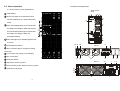
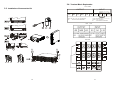
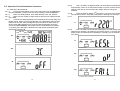
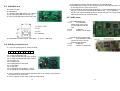
2.3.2 Rear Panel Explanation
2.3. Panel explanation
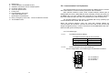
2.3.1 Front Panel Function Explanations
5K/6K with batt
Model
LCD Display
D
CB A
Green LED lights up to indicate the UPS
Parall el Work Comm.
Bus Not I nt ended t o
TNV Communication Network
RS23 2
G
Slo t
has the capability to run under redundancy
N
G
-
+
Ext. Batte r y
EPO
mode.
F
Green LED steadily lights up to indicate that
the utility input voltage is within the window;
Utility Inp ut
Br eake r
the LED flashes flickeringly to indicate that
I
the utility input voltage is within the
L
acceptable window.
OU TPU T
G2 N22 L2 1
G1
INPU T
N 1 L1 2
L 21-N2 2: UPS O UTPU T L12-N1 : UT IL IT Y INPUT
G 2 : OUTPUT E ARTH G 1 : INPUT EA RT H
G ROUN D
G ROUN D
Green LED lights up to indicate Bypass Input
P
PAT. NO .:
US 690 6501 , TW 202 668
is normal.
B A N
UPS ON/Alarm Silence
P
I
5/6k PM
Go to Previous page or change the setting
RS232
EPO
S1
ON
To reconfirm the change of UPS Setting
Parallel Work Comm.
Bus Not Intended to
TNV Communication Network
OUTPUT
of the UPS
OF F
Ext. Battery
G2
N22
INPUT
L21
G1
N1
L1 2
G
+
CB 1
Ut il it y In put
Breaker
Go to next page
C G
UPS OFF Switch
F
L
10K PM
Special Functions log in/out
I
J P
EXT.
BATTERY
-
+
RS232
N
SLOT
S1
ON OFF
EPO
G
BYPAS S
INP UT
BREAKER
TB1
Not Intended to
TNV Communication
Network
A
B
C
D
TB2
F
8
G
E
UTILITY
INP UT
BREAKER
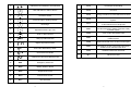
UPS is working under ECO ( Economic ) Mode
UPS fault or Abnormal
D
L
9