1
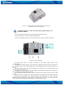
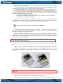
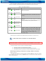
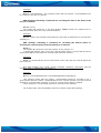
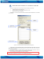
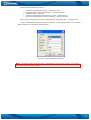
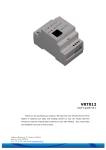
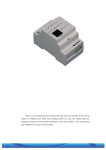
VRT014
User‘s guide V0.8
Thank you for purchasing our product. We hope this user-friendly device will be
helpful in realising your ideas and bringing comfort to your life. Please take few
minutes to read this manual before starting to work with VRT014. This would make
the installation and use of device easier.
Address: Saltoniškių g. 10c, Vilnius LT-08105,
Phone: (370-5) 2127472,
Fax: (370-5) 276 1380, Email: [email protected]
i
INTRODUCTION
VRT014 is a very simple device which can be used for authorised door access,
controlling gates, switching of remote equipments, car parking systems, activate/deactivate
alarm systems and etc. Basically this device can be used in places which require ON/OFF
switching action. This ON/OFF functionality of VRT014 can be achieved by making a phone
call.
Whenever a person calls VRT014, the device compares the phone number of incoming
call with the numbers stored in the memory of device. If a match is found, it means the
caller is an authorized person. Due to this VRT014 will turn ON its’ output, in short, sending
a signal to activate the connected device. VRT014 does not have any answer function;
therefore, the calling person does not have to pay any charges for the call.
Up to 500 different numbers can be stored in the memory of device.
In additional you can turn ON the relay by using an external switch input. When a
logically low signal is given to this input the output will be turned ON.
VRT014's output turns OFF always after relay‘s timeout. The timeout is programmable
VRT014 can be configured in two ways,
a) By sending an SMS
b) By connecting the device to a PC using COM port interface and the VRT014
configuration software.
i
PACKAGE CONTENTS
Cardboard box.
Device VRT014.
CD (including the required information and software.)
Configuration cable for connection between the device and personal computer
GSM antenna.
Quick start guide
Note: The package does not include any SIM card. The SIM card must be acquired from
your GSM service supplier.
If any part from the package is missing, please contact your local dealer, seller or the
business representative.
i
TECHNICAL SPECIFICATIONS
Power Supply Voltage
Average Power consumption
Operating Temperature
Maximum Switching Current
Maximum Switching Voltage
Relay programmable timeout
Dual Band GSM modem TM1
Dimensions
9…15 VDC
2W
-20°C...+40°C
5A
240VAC, 30VDC
0,5...65 sec
900/1800MHz
90mmx58mmx53mm
2
Picture 1. External view and measurements of the device
Dimension: 90 x 58 x 53 (mm)
i
DESCRIPTION OF THE DEVICE AND PRINCIPLES OF
FUNCTIONING
The device VRT014 consists of a microcontroller and GSM modem.
The microcontroller receives and processes signals.
There are 4 light diodes on the external board of the device as shown in picture 2.
Picture 2. Device VRT014
The light diode Power is directly connected to the Power supply chain of the
microcontroller.
The light diode Modem State is connected to the GSM modem and its status depends on
the operation logic of the GSM modem and its specifications (The diode may have no
flashing).
The light diodes Relay and Signal Strength are connected to the microcontroller and
reflect the status of the device.
The light diode Relay reflects the signal status of activating the internal relay. When the
relay is activated, the light diode is also on.
The light diode Signal Strength reflects the Power of the signal received via the GSM
modem.
When the Power is supplied, the light diodes Relay and Signal Strength reflect the start
of activating the programme and its various stages. If the connection is correct, the light
diodes are flashing alternately as specified in the table below, and when the operation status
is activated, they are operating in accordance to their main functions.
3
When the Power is supplied, the device checks the whole internal data base of numbers
and operation of the memory chip.
If there is a memory error, the device would not switch to operation mode and 2 pulses
would be emitted by alternately by the light diode Signal Strength.
If the GSM modem is not functioning, the device would not switch to operation mode
and uninterrupted swift short pulses would be emitted by the light diode Signal Strength.
In the device, the whole internal data base of numbers is being checked by checking
the control counting (CRC). If the control counting does not match, the device would rewrite
all settings back to manufacturer’s values:
•
The enabling of the external switch signal.
•
The time for switching off the relay is set at 5 sec. However, it is not being used.
•
The data base of numbers is deleted.
When the device is operating, it is possible to connect a personal computer and do the
configuration. In addition, when data is being transmitted from the device to the personal
computer and vice versa, it does not respond to calls and SMS messages.
i
MAKING THE DEVICE READY FOR WORK
After purchasing the device it needs to be configured, i. e. the list of numbers which the
device would respond to must be recorded in the memory as well as the parameters of the
switching-on signal of the operating device.
When the device is switched on for the first time, its data base of numbers is empty.
The device must be configured by a personal computer and a programme since the
configuration command by SMS messages may be received only from numbers which are
already available in the data base.
Note: The configuration can be done after the device is bought or at a later stage, when
the device has been prepared for use.
The device is fixed onto DIN board and connected as shown in the labelling on the
body.
Before using the device, insert a SIM card with an unlocked PIN code check. PIN code
check may be unlocked by any mobile phone or other appropriate device. For more
comprehensive information, please refer to the internet service provider, the owner of the
SIM card.
Picture 3. Inserting SIM card
Note: the SIM card may only be inserted while the power supply of the device is
unplugged.
After the device is switched on and configured, it is ready for use.
When the device is turned on for the first time, please see if it is properly switched on.
4
One only needs to watch the signals of the light diodes: if the device is switched on
properly, the signals of the light diodes would be activated as specified in the table.
Table 1. Boot stage sequences
Turn-by-turn signals of light
diodes
Power
Modem state
Relay
Signal strenght
Power
Modem state
Relay
Signal strenght
Power
Modem state
Relay
Signal strenght
Power
Modem state
Relay
Signal strenght
Power
Modem state
Relay
Signal strenght
Description of the status
Light diode Power is turned on and starts shining
without interruptions.
The light diode Modem State may flash in accordance
of the GSM modem logics. (The diode may have no
flashing).
Light diodes Relay and Signal Strength are flashing
by turns.
This status lasts as long as the modem is in progress
of being connected to the operator’s network.
When the modem has been connected to the
operator’s network, the light diode Relay stops
flashing and the light diode Signal Strength starts
flashing to reflect the Power of the signal being
received. The light diode is pulsing, and the quantity
of pulses refers to the Power of the signal.
One pulse refers to the lowest signal, 7 pulses refer o
the highest signal.
When the device reaches the last stage specified in the table, it is ready for use.
i
CONFIGURATION BY MEANS OF SMS MESSAGES
Note: the device will not respond to SMS that contains configuration commands, unless
senders phone number is entered to 0th position in internal database of phone numbers
The device is able to receive 3 types of command messages:
1.
2.
3.
Recording a number in the data base of numbers
Recording the time of the delayed switching-off-the-relay signal
Recording the status of receiving an external switching-on-the-relay signal
SMS message containing a command for recording a number is as follows:
P#nnn=xxxxxxx;
The symbol “P” should be in the first position, instead of nnn there must be a number
to be recorded in the device memory, xxxxxxx means a recorded phone number which the
device would respond to.
5
Example:
P#001=+37012345678; - this message means that the number +37012345678 must
be recorded in the first (1) position.
SMS message containing a command for recording the time of the delay of the
relay is as follows:
PRTIMT=xxxxx;
The symbol “P” should be in the first position, xxxxx means the recorded time in
miliseconds within which the relay would be delayed.
Example:
PRTIMT =5000; this message means that the relay must be delayed for 5 seconds after
switching on.
SMS message containing a command for recording the altered status of
receiving an external signal (external switch) is as follows:
PSEN=x;
The symbol “P” should be in the first position, x may mean 0 or 1.
1 means that VRT014 can't receive the external switch signal. 0 means that the device
would switch ON the relay after the external signal has been received.
Example:
PSEN =0; means that the device would switch on the relay after the external signal has
been received.
One SMS message may contain several messages containing commands, and the
messages must be separated by the symbol “;”.
Example:
P#001=+37012345678;#002=+37023456789;RTIMT=5000;SEN=1;
This message means that the number +37012345678 should be recorded in the 1
(first) position and the number +37023456789 in the 2 (second) position, the relay must be
delayed for 5 seconds after switching on and the external switch signal is disabled.
There should be no unnecessary symbols or intervals in the message.
The changes take effect immediately after the reception of the SMS message.
6
i
CONFIGURATION BY MEANS OF A PERSONAL COMPUTER
In order to configure the device using a personal computer you should:
•
•
•
Install Remote Switch Configurator
Connect VRT014 to a PC using a configuration cable
Start Remote Switch Configurator
In picture 4. you can see the main window of Remote Switch Configurator. It is divided
into 3 sections
Relay
configuration
Search of a
number in the list
The list of
numbers
Control buttons
Picture 4. The main window of Remote Switch Configurator
Configuration of relay allows the device to switch from ON to OFF mode of the inner
relay. Device can switch modes automatically after a number of ms, which can be entered in
Relay Timeout (ms) field.
If an external source of a signal (button or other sensor) will be required in order to
switch ON mode, you should no place a tick at Disable External Switch.
You can add up to 500 numbers in the list of numbers.
Note: you should add „+“ sign in front of every number.
Remote Switch Configurator for VRT012 is not compatible with VRT014.
7
Control buttons should be used to:
•
•
•
•
•
Load the configuration from file - Load From File...
Read the configuration of the device - Load From Device
Delete all fields - Clear All
Save the configuration of the device to a file – Write To File…
Save the configuration to device’s memory – Write To Device.
Start working with Remote Switch Configurator by configuring port – Configure Port.
A port configuration window is shown in picture 5. You should select a Port which a
device VRT014 is connected to and press OK.
Picture 5. Port Configuration Window.
Note: you should restart the device after configuration is saved to its' memory. Just unplug
the power source and plug it again.
8
i
METHOD OF OPERATION
For the switching-on signal to be activated (the connection of internal relay contacts),
the user has to dial the device’s SIM card number. After having received one or two calls,
the device rejects it, if the call matches one of the numbers available in the internal data
base of the device. If the number does not match, the device would not respond to calls.
The device rejects the switching-on signal then the delay time runs out, depending on
the configuration of the device.
When the device is operating, the list of numbers available in its memory may be edited
by means of SMS messages.
Note: device responds SMS that come from the number which was entered at 0th position
in the internal data base of numbers.
i
IMPORTANT
The sign on the packaging means that the user’s manual provided on a compact
disk must be read before using the product.
The sign on the packaging means that the electric and electronic equipment to
be utilised must be stored separately.
i
AND LAST…
In case you have problems with the installation and use, please address them to the
Technical Assistance Department by e-mail [email protected].
4
9