1
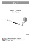
NOTICE D’UTILISATION USER MANUAL Spy RF Modem Ethernet 08916B ©JRI Maxant 1 TABLE OF CONTENTS I. INTRODUCTION .......................................................................................................................................................... 16 a) Equipment................................................................................................................................................................................ 16 b) Symbols ................................................................................................................................................................................... 16 II. INSTALLATION RECOMMENDATIONS ................................................................................................................................. 16 a) III. Perturbations sources ............................................................................................................................................................ 16 INSTALLATION ........................................................................................................................................................................ 17 a) Installation recommendations ............................................................................................................................................... 17 b) Installation of wall-mounting bracket .................................................................................................................................... 17 c) Complementary information .................................................................................................................................................. 17 IV. CHARACTERISTICS ................................................................................................................................................................ 18 V. INSTALLING SPY RF ETHERNET MODEM............................................................................................................................ 18 VI. WARRANTY ............................................................................................................... ERREUR ! SIGNET NON DEFINI. VII. MAINTENANCE CONTRACT ...................................................................................................................................... 27 VIII. ENVIRONMENT PROTECTION ................................................................................................................................... 27 ©JRI Maxant 15 I. Introduction Congratulations, you own a SPY RF Ethernet Modem ! This device is equipped with 1 or 2 inputs (digital or logical…). It enables you to record 1 or 2 physical parameter (depending on the model) and to transfer wireless the recorded data by radio frequency to a PC. The SPY RF Ethernet Modem complies with EN 12830, only with temperature probes. a) Equipment 1 SPY RF Ethernet Modem 1 wall-mounting bracket 1 connector protection b) Symbols 1 user manual 1 adhesive plaster RECYCLING : do not throw in a rubbish dump or in a domestic waste container. Comply with the regulation to throw away the device. POWER SUPPLY : this device is powered by a continuous current delivered by a main power supply adaptor (230VAC). Comply with the security and utilization regulations of electric power. Use an electric installation complying with these regulations CE MARKING :this equipment is certified to comply with the European regulation for the electric security, inflammability, disturbing radiation emission and immunity to surrounding electric disturbances. FCC ID: 09586 / 09587 This device complies with Part 15 of the FCC Rules. Operation is subject to the following two conditions: (1) this device may not cause harmful interference, and (2) this device must accept any interference received, including interference that may cause undesired operation In accordance with FCC requirements, changes or modifications not expressly approved by JRI Maxant could void the user's authority to operate this product. NOTE: This equipment has been tested and found to comply with the limits for a Class A digital device, pursuant to Part 15 of the FCC Rules. These limits are designed to provide reasonable protection against harmful interference when the equipment is operated in a commercial environment. This equipment generates, uses and can radiate radio frequency energy and, if not installed and used in accordance with the instruction manual, may cause harmful interference to radio communications. Operation of this equipment in a residential area is likely to cause harmful interference in which case the user will be required to correct the interference at his own expense II. INSTALLATION RECOMMENDATIONS The Spy RF is a recorder of physical parameters able to communicate wirelessly with the operating software SIRIUS. The wireless communication is based on radio frequency. As we are daily in contact with it (radio, TV…) it is easy to think that it always works. This is true if basic rules on the positioning of recorders are respected because wireless communication is subject to perturbations. a) Perturbations sources Presence of obstacles in the way of the waves between the Spy RF ModeM and the Spy Rf (wall, ceiling, person, furniture…) or close to the antenna. Obstacles thickness in the way of the waves. The absorption is more important in diagonal as perpendicularly Waves cannot pass through full metallic walls. On the other hand, a perforated wall allows the waves passing with attenuation ©JRI Maxant 16 III. INSTALLATION a) Installation recommendations Place the devices at ~2m high and around 30 to 40cm from the ceiling to avoid obstacles and moving persons. If possible, place the Spy RF in central position regarding the Spy RF recorders. Try to place them preferably at sight of each other. On the wall, it is preferable to them aside by using the special bracket (ref 08512) of the catalog. Place the antenna above the top of the monitored unit (fridge, incubator, oven, cold rooms…). Never place the Spy RF horizontally. If some difficulties persist, it is possible to use Spy Rf RelaY (repeaters) or to connect another Spy RF ModeM to the Ethernet network (LAN). b) Installation of wall-mounting bracket Furniture c) Bracket mounting Complementary information Installing Connecting Bouton reset Sortie relais ©JRI Maxant 17 IV. CHARACTERISTICS Operating range StorageTemperature range Radio range (in free field) Radio band Transmitting power Power supply Rechargeable battery autonomy without power supply Dimensions Relay output CE ERM conformity 0+40°C 0-90%HR non condensed -40 + 85°C 1km 868MHz – 902 MHz 25 / 500mW 9V DC 650mA or through Ethernet* NIMH 6V from 4 to 6h 153 x 82 x 35mm 36V DC - 1A EN 301 489 / EN 61000 / EN 61010 EN 55022 / EN 300 220 *fournie pour le marché européen / Supplied for european market V. INSTALLING SPY RF ETHERNET MODEM The Modem SPY RF Ethernet is fitted with a module DIGI CONNECT ME for which the installation procedure is as follows: 1) Installing drivers Digi Connect ME The installation must be made for each RF Modem SPY Ethernet used on the network. Connect all modems to be used on the network and connect them to the power supply Use the installation CD that came with the modem; the “Digi Device Setup Wizard” application will automatically start. ©JRI Maxant 18 Click on Next – the list of Digi Connect ME devices that are available on the network is then displayed,, each with its IP address (fixed or issued by the DHCP server) and its MAC address. The modules are visible 2 to 3 minutes after installation. Select the device you wish to install, and Next Choose fixed IP Address mode (check "use the following IP settings"), enter an IP address (provided by the network administrator or proposed by the PC; eg. 192.168.0.1) and enter a subnet mask (for example: 255.255.255.0); then select Next Select in the list the scenario “REAL PORT” (redirection of port com), and Next ©JRI Maxant 19 A summary of choices is displayed on the screen. If everything is OK, click on Next ©JRI Maxant 20 The RealPort software is installed and the installation program stops. Select "log on to web user interface of device” and select Finish The screen of Web Digi Connect ME appears; enter "root" for the username and "dbps" as a password The various sections of the Web interface allow access to all the resources of Digi Connect ME Selection of “ Serial Port” in the Setup menu followed by the selection of “Port1” enables the user to check the programming in “Real Port”. ©JRI Maxant 21 Save “System Configuration” (copy screen) Select “Update Firmware” in the: “Administration” Menu Collect all firmware and Post versions The web interface allows to perform optimization operations of the driver and DIGI ONE update operations -See section OPTIMIZATIONS § 4.3- Do not close this window in case you need to update drivers Reboot – « Administration » Menu NB : This procedure can be performed either by the application "Digi Port Authority” installed by the CD, either by the application "Digi Device Discovery," available on CD with a simple user interface, which must be installed separately 2) Setting serial ports for Sirius Once installation of Digi Connect ME completed, these modules can be accessed by Window via' virtual serial ports. " To determine the number of a serial port assigned to a specific Digi Connect ME module, in order to set up a distant modem in Sirius, proceed as follows: Open Device Manager in Windows. ©JRI Maxant 22 OR U Keys Windows + Break In the Directory “Port” (COM & LPT), check the virtual COM port used for each Digi Connect ME module. To avoid confusion, identify each module by its IP address by opening the Properties window (right click on the line Digi Connect ME) and going on the General tab. The Spy RF ModeM Ethernet is now installed. It must be displayed in the device manager (SIRIUS) ©JRI Maxant 23 3) Procedure in case of malfunction? Set a new configuration by connecting directly the modem onto the network port of the PC, using an Ethernet cable.. The PC should not be connected to the network. 4) Optimizations After installation of an Ethernet modem you must ensure that the communication between the modem and Sirius takes place within a delay that is compatible with the application. The simplest way to proceed is to empty the memory of a satellite and check if the emptying time is correct. If the emptying procedure takes more than 5 minutes (1 minute for one day measures ) it is imperative to carry out a parameter setting. 4.1) Verification of Firmware DIGI Connect ME At the Web interface “Administration / Update Firmware” enables to update the firmware embedded in the Digi Connect ME modules. The updated versions are as follows: Les drivers se trouvent sur le CD de Sirius. Drivers are available on the Sirus CD Matériel DIGI Connect ME (Modem Ethernet) Version POST Version Firmware 82000867_G (1.1.3) 82000856_F6 (1.9.0.6) Version Driver REAL Port 3.6.325.0 The POST is the program used to download the firmware ; if not updated it must be downloaded at first. After each download of a Digi One module, a “Reboot” procedure is proposed; Accept this procedure. 4.2) Checking of the REAL PORT Driver used The versions of the firmware and of the drivers are available on the CD, in the directory “Drivers”, or on the website of DIGI-www.digi.com support section-drivers. The version that has been tested and that is compatible with LAN and WAN connections is version: 3.6.325.0 of 17/11/2006 To know the driver version that is activated: Right click workstation + tab material of the properties Menu (or Control Panel + system + equipment). Select device manager. In « multi-port card » select the concerned DIGI ©JRI Maxant 24 Right click on Properties The tab « Driver » shows the driver version in use. To modify the driver of the Digi Connet ME module : Select « Driver Update » Choose the location where you have previously stored files (CD or USB key eg) After updating the Driver, reboot of the PC is required. Otherwise programming § 4.3 is not available. 4.3 - Programming the response time This adjustment is necessary as it is often the cause of a slow communication. Right click workstation properties tab “material” (or Control Panel + system + equipment). Select « device manage r ». In « multiport card », select the DIGI you need to program Right click on Properties Select the tab “Advanced” and click on “properties” in the lower right corner Select « port 1 », then “Set Profile” ©JRI Maxant 25 Optimization of the driver 3.6.325.0 In the « Set Port Profile » Menu, select “Typical Settings” if you wish a LAN application (local area network) Choose “Less Overhead” if you wish a WAN application (remote network) ©JRI Maxant 26 VII. WARRANTY JRI Maxant products carry a one year warranty and guarantee against defects in their components or workmanship. During this period if any product supplied by the Company proves on inspection to be defective, the Company will at its own option replace the same or refund to the Buyer the price of the product. In no circumstances will JRI Maxant' liability exceed the price of the product paid by the buyer or the cost of replacement. JRI Maxant shall not in any event be liable to the Buyer for any indirect or consequential loss or damage costs or expenses whatsoever which might arise out of or in connection with the supply of the product or its consequent use. Consequently, the products warrantee and guarantee specified above, does not cover damage caused by fair wear and tear, abnormal storage conditions, incorrect use, accidental misuse, abuse, neglect, misapplication or modification, or use with non-JRI Maxant' hardware/software. No warranty of fitness for a particular purpose is offered and the user assumes the entire risk of using the product. In line with our policy of continuous development, we reserve the right to amend our product specification without prior notice. VIII. MAINTENANCE CONTRACT How to optimize your radio frequency installation? RF measuring systems communicate by radio frequency. However, there may be several factors that can modify the radio ways already defined, such as moving from a building, adding walls, … Radio frequency requires thus a periodical follow up performed by specialists. That’s why JRI Maxant has created maintenance contracts. We bring you a global solution which makes your maintenance easier. This overall service offer includes maintenance and also metrological services, which ensure you that your system is fully performant. You won’t worry about your devices maintenance anymore ! With this maintenance contract you will benefit for a minimal period of 2 years from the following advantages: - material verification once or twice a year - warranty extension - telemaintenance - telephone assistance +33 (0) 892 680 933 (0,282 € HT/min) - material replacement on site or by return in our manufacture - metrological certificates: verification of measurement accuracy - access to new software versions and updates - on-site intervention time within 3 open days after problem identification by our experts IX. ENVIRONMENT PROTECTION JRI Maxant recommends to our customers to throw away their measuring and recording devices which are unserviceable and/or beyond repair in a way that is appropriate to environment protection. Insofar as the production of waste cannot be avoided, it is best to re-use them by proceeding with adapted recycling depending on the material used and considering the environment protection. RoHS Directive The ROHS European Directive rules and limits the presence of hazardous substances in electrical and electronic equipments (EEE). In the article 2, the scope of this Directive excludes "9. Monitoring and Control Instruments" and our products are part of this category. Nevertheless, our company has decided to apply the whole dispositions of this Directive for all our new electronic devices which will comply to this 2002/95/CE Directive. ©JRI Maxant 27