1
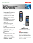
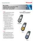
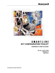
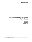
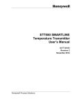
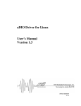
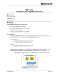
Installing the Communication Module Instruction sheet for SmartLine Transmitters: ST 700 and ST 800 Pressure Transmitters, STT 850 Temperature Transmitter and SLG 700 Level transmitter Document Number: 34-ST-33-69 Effective Date: 5/31/2015 (STT 850 Temperature & SLG 700 Level Transmitter added) Supersedes: 11/26/2013 Installing Communication Module See page 6 for Installing DE Communications Module (DE not supported by SLG 700 Level) The Communication module includes a connector to the sensor ribbon cable (not applicable for STT 850) and a connector to the optional Display module. This section includes the procedure to replace the Communication module and external button configuration assembly. Please take appropriate steps to avoid ESD damage when handling the Communication and Display Module assemblies Refer to Figure 1 for parts locations Step – 1: When installed as explosion-proof or flame-proof in a hazardous location, keep covers tight while the transmitter is energized. Disconnect power to the transmitter in the non-hazardous area prior to removing end caps for service. When installed as non-incendive or non-sparking equipment in a hazardous location, disconnect power to the transmitter in the non-hazardous area, or determine that the location is non-hazardous before disconnecting or connecting the transmitter wires. When removing the Communications Module with power applied, the loop will go to 0V. Likewise, installing a Communications Module into a transmitter with power applied will cause the loop output value to go to 12 ma for several seconds then the loop output value will go to the configured value based on the PV input. Installing a Display Module into a powered transmitter may cause a temporary upset to the loop output value. 34-ST-33-69 Communications Modules 1 Step – 2: Loosen the end cap lock, and unscrew the end cap from the electronics side of the Transmitter housing. Step – 3: If equipped with a Display module, carefully depress the two tabs on the sides of the Display Module, and pull it off. Do not discard the Display module. Step – 4: If necessary, unplug the interface connector from the Communication module. Do not discard the connector. Step – 5: Loosen the two retaining screws, and carefully pull the Communication module from the Electronics compartment. Step – 6: Carefully remove the Sensor Ribbon Cable (not applicable for STT850) from the "P2" connector on the Communication module at the bottom of the Communication module. Step – 7: Carefully align and connect the Sensor Ribbon Cable (not applicable for STT 850) to the connector “P2” at the bottom of the replacement Communication module. NOTE: For SLG 700 Level transmitters only. When connecting 12 pin ribbon cable assembly (K1), of the Power Accumulator board to the 10 pin connector, “P2” on the Fieldbus Comms board, make sure that the offset is maintained correctly. Pin 1 of the Power Accumulator (K1) assembly should match pin 1 of Fieldbus Comms board “P2” connector. When connected in this fashion, pins 11 and 12 of the ribbon cable assembly connector will be unconnected. Figure 1: Level transmitters only - Ribbon Cable Assembly and Fieldbus board Step – 8: Carefully, insert the replacement Communication module into the Electronics compartment. Ensure that the Sensor Ribbon Cable is not pinched (not applicable for STT 850). Step – 9: Tighten the two Communication module retaining screws. 34-ST-33-69 Communications Modules 2 Step – 10: Refer to the SmartLine User's Manual to change the FAILSAFE, READ/WRITE, and SIM-OFF/SIM-ON (Fieldbus Only) configuration settings. Step – 11: If applicable, re-install the Display module as follows: • • • Orient the display as desired. Install the Interface Connector in the Display module such that it will mate with the socket for the display in the Communication module. Carefully line up the display, and snap it into place. Verify that the two tabs on the sides of the display latch. Orient the Display for proper viewing through the end cap window. You can rotate the meter mounting orientation in 90 o increments. Step – 12: Apply Parker Super O-ring Lubricant or equivalent to the end cap O-ring before installing the end cap. Reinstall the End Cap and tighten the End Cap locking screw. NOTE: Field Upgrades only should come before Step 13 Step – 13: Installing Optional External Configuration Button Assembly. Loosen (Do Not Remove) both top nameplate screws and pivot nameplate 90°. Align the protrusion on the button assembly with the matching opening in the housing and snap the button assembly into the housing. Rotate the nameplate back to the original position, and tighten the nameplate screws. (Steps 14 – 17 required for Field Upgrades Only) Step – 14: Loosen the End Cap locking screw and unscrew the End Cap from the Field Wiring side of the transmitter housing. Step – 15: Select the proper Communication/External Configuration upgrade kit label from the label strip provided and adhere to the inside of the Field Wiring compartment End Cap. Step – 16: Apply Parker Super O-ring Lubricant or equivalent to the end cap before installing the end cap. Reinstall the End Cap and tighten the end cap locking screw. Step – 17: Install external upgrade label (i.e. DEVICE MODIFIED…..) provided on outside of housing as shown in Figure 2. Step – 18: Restore power if removed. Step – 19: Check the settings of the Transmitter Setup and Display Setup parameters to make sure that the transmitter is configured correctly for your application. Reference documentation Transmitter User’s manual HART/DE Option manual Fieldbus option manual ST 700 ST 800 STT 850 SLG 700 #35-ST-25-44 #34-ST-25-35 #34-TT-25-03 #34-SL-25-11 #34-ST-25-47 #34- ST-25-38 #34-TT-25-06 #34-SL-25-06 #34-ST-25-48 #34-ST-25-39 #34-TT-25-07 Future release 34-ST-33-69 Communications Modules 3 Step – 20: If applicable, verify External Button Configuration operation. Figure 2 – Communication module replacement (Sheet 1) 34-ST-33-69 Communications Modules 4 Figure 3 –Communication module replacement (Sheet 2) 34-ST-33-69 Communications Modules 5 Installing DE Communication Module (DE is not supported by SLG 700 Level transmitters) The instructions below must be followed in order to retain the transmitter’s Configuration Database when replacing a DE Communications module. Transmitter connected to a TPS/TDC System Step – 1: Make the transmitter Tag Inactive. Step – 2: Go to the “Smart Transmitter Data” Section in the Configuration Page of the Transmitter. Step – 3: Select Command as “UPLOADDB”. This command uploads all the Transmitter configuration data to the Host. Step – 4: Wait for the Parameter STATE to indicate “LOADCOMP”. This confirms that Upload of all transmitter data has completed. Step – 5: Now you can Power Off the Transmitter and replace the DE Communication Board as per the instructions provided in Step1 on Page 1 of this document. Step – 6: Power on Device, Check the Display for no error messages. Step – 7: Return back to the “Smart Transmitter Data” Section in the Configuration Page of the Transmitter. Step – 8: Select Command as “DNLOADDB”. This command downloads all the Transmitter configuration data from the Host to the Device. Step – 9: Wait for the Parameter STATE to indicate “LOADCOMP”. This confirms that Download of all transmitter data has completed. Step – 10: Make the transmitter Tag Active. Step – 11: The Updated Firmware Version for DE Transmitter can be confirmed in the following ways: • • • ST 800 Transmitters with Local Zero and Span Option (Reed Switch) and Advanced Display: - Navigate to Main Menu >> Information >> Elec Module - Confirm that the “Firmware Version” is at the expected level ST 700 Transmitters with Local Zero and Span Option (Reed Switch) and Basic Display: - Navigate to Firmware >>Electronics - Confirm that the “Firmware Version” is at the expected level ST 800 or ST 700 Transmitters without Local Zero and Span ( Reed Switch) the firmware version can be confirmed on the TPS/TDC Host: - Go to the “Smart Transmitter Data” Section in the Configuration Page of the Transmitter. - Confirm that Parameter value for “STISWVER” is D.3 Attention! – The information in the “Transmitter Scratch Pad” parameter may be lost during this procedure. This parameter does not hold any critical configuration data. 34-ST-33-69 Communications Modules 6 Transmitter connected to an Experion System Step – 1: Make the transmitter Tag Inactive Step – 2: Go to the “Smart Transmitter Tab” of the Block Properties Page. Step – 3: Select Command as “UpLoadDb”. This command uploads all the Transmitter configuration data to the Host Step – 4: Wait for the Parameter “Current State” to indicate “Loadcomp”. This confirms that Upload of all transmitter data has completed. Step – 5: Now you can Power Off the Transmitter and replace the DE Communication Board as per the instructions provided in Step1 on Page 1 of this document. Step – 6: Power on Device, Check the Display for no error messages. Step – 7: Return back to the ““Smart Transmitter Tab” of the Block Properties Page. Step – 8: Select Command as “DnLoadDb”. This command downloads all the Transmitter configuration data from the Host to the Device. Step – 9: Wait for the Parameter “Current State” to indicate “Loadcomp”. This confirms that Download of all transmitter data has completed. Step – 10: Make the transmitter Tag Active. Step – 11: The Updated Firmware Version for DE Transmitter can be confirmed in the following ways: • • • ST 800 Transmitters with Local Zero and Span Option (Reed Switch) and Advanced Display: - Navigate to Main Menu >> Information >> Elec Module - Confirm that the “Firmware Version” is at the expected level ST 700 Transmitters with Local Zero and Span Option (Reed Switch) and Basic Display: - Navigate to Firmware >>Electronics - Confirm that the “Firmware Version” is at the expected level ST 800 or ST 700 Transmitters without Local Zero and Span (Reed Switch) the firmware version can be confirmed on the Experion Host: - Go to the “Smart Transmitter” Tab in the Block Properties Page. - Confirm that Parameter value for “Software Revision” is D.3 Attention! – The information in the “Transmitter Scratch Pad” parameter may be lost during this procedure. This parameter does not hold any critical configuration data. 34-ST-33-69 Communications Modules 7 Transmitter connected to a MCToolkit Handheld Step – 1: Connect the MCToolkit with the DE Device. Step – 2: Select MCToolkit Program. Step – 3: Go to Online Mode and Upload the database. Step – 4: Once the database is uploaded, in DE main menu go to option “Save to File”. Step – 5: Save the uploaded configuration in SD Card or main memory. The configuration will be saved in “.xml” format. Step – 6: Now you can Power Off the Transmitter and replace the DE Communication Board as per the instructions provided in Step1 on Page 1 of this document. Step – 7: Power on Device, Check the Display for no error messages. Step – 8: Again connect the MCToolkit with the DE device. Step – 9: Go to the Offline configure tab, and select the earlier saved .xml file. Step – 10: After selecting the appropriate configuration file, enter the file management tab on same window. Step – 11: Cross check the configuration and press “DOWNLOAD to Device”. This will download the configuration. You can upload the database by taking the device online. Step – 12: The Updated Firmware Version for DE Transmitter can be confirmed in the following ways: • • • ST 800 Transmitters with Local Zero and Span Option (Reed Switch) and Advanced Display: - Navigate to Main Menu >> Information >> Elec Module - Confirm that the “Firmware Version” is at the expected level ST 700 Transmitters with Local Zero and Span Option (Reed Switch) and Basic Display: - Navigate to Firmware >>Electronics - Confirm that the “Firmware Version” is at the expected level ST 800 or ST 700 Transmitters without Local Zero and Span (Reed Switch) the firmware version can be confirmed on the MCToolkit Handheld: - Go to Go to the "Device Info" tab in the DE Main menu. - Confirm that Parameter value for “Firmware Revision” is D.3 Attention! – The information in the “Transmitter Scratch Pad” parameter may be lost during this procedure. This parameter does not hold any critical configuration data. 34-ST-33-69 Communications Modules 8 Transmitter connected to Smart Field Communicator (SFC) Step – 1: Connect the SFC with the DE Device. Step – 2: Press [SHIFT] “ID” to read Tag ID. This step will identify the Device Step – 3: Once the ID is read successfully, press “CONF” to read the configuration of device. The Screen will show status as “SFC working..”. Step – 4: Once the read is complete, Follow the below sequence in the SFC to Save Configuration data from the Device to SFC “NEXT”>> “NEXT”>> “NEXT”>> [NEXT] >> “SAVE/RESTORE?” >> YES” >> “SAVE DATA?” >> “YES”>>”ARE YOU SURE”>> “YES” Saving of Data will start. Step – 5: Once the data saving is complete the SFC will display message as “DATA SAVED”. Attention! – After the SAVE Operation is complete do not navigate to any other menu on the SFC or Power off the SFC Step – 6: Now you can Power Off the Transmitter and replace the DE Communication Board as per the instructions provided in Step1 on Page 1 of this document. Step – 7: Power on Device, Check the Display for no error messages. Step – 8: Again connect the SFC with the DE Device. Step – 9: On the same Menu as Step 5, Follow the below sequence in the SFC to Restore Configuration data from the SFC to Device “NEXT”>>> ”SAVE/RESTORE” >> UP ARROW>> “RESTORE DATA”>> “YES” >> “SFC WORKING” >> “DATA RESTORED” Restore operation would take a few seconds to complete. Step – 10: Put transmitter back into DE mode by Press [SHIFT] [A <-DE] Step – 11: The Updated Firmware Version for DE Transmitter can be confirmed in the following ways: • • • ST 800 Transmitters with Local Zero and Span Option (Reed Switch) and Advanced Display: - Navigate to Main Menu >> Information >> Elec Module - Confirm that the “Firmware Version” is at the expected level ST 700 Transmitters with Local Zero and Span Option (Reed Switch) and Basic Display: - Navigate to Firmware >>Electronics - Confirm that the “Firmware Version” is at the expected level ST 800 or ST 700 Transmitters without Local Zero and Span (Reed Switch) the firmware version can be confirmed on the SFC - Press “SHIFT” + “SW VER” - Confirm that Parameter value for “XMTR” is D.3 34-ST-33-69 Communications Modules 9 Sales and Service For application assistance, current specifications, pricing, or name of the nearest Authorized Distributor, contact one of the offices below. ASIA PACIFIC EMEA AMERICA’S Honeywell Process Solutions, Honeywell Process Solutions, Honeywell Process Solutions, (TAC) [email protected] Phone: + 80012026455 or +44 (0)1344 656000 Phone: (TAC) 1-800-423-9883 or 215/641-3610 Australia Honeywell Limited Phone: +(61) 7-3846 1255 FAX: +(61) 7-3840 6481 Toll Free 1300-36-39-36 Toll Free Fax: 1300-36-04-70 Email: (Sales) (Sales) 1-800-343-0228 [email protected] Email: (Sales) or [email protected] (TAC) or [email protected] (TAC) [email protected] China – PRC - Shanghai Honeywell China Inc. Phone: (86-21) 5257-4568 Fax: (86-21) 6237-2826 Singapore Honeywell Pte Ltd. Phone: +(65) 6580 3278 Fax: +(65) 6445-3033 South Korea Honeywell Korea Co Ltd Phone: +(822) 799 6114 Fax: +(822) 792 9015 For more information To learn more about SmartLine Pressure Transmitters, visit www.honeywellprocess.com Or contact your Honeywell Account Manager Process Solutions Honeywell 1250 W Sam Houston Pkwy S Houston, TX 77042 Honeywell Control Systems Ltd Honeywell House, Skimped Hill Lane Bracknell, England, RG12 1EB Shanghai City Centre, 100 Jungi Road Shanghai, China 20061 www.honeywellprocess.com 34-ST-33-69 May 2015 2015 Honeywell International Inc.