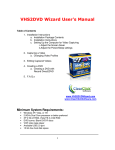
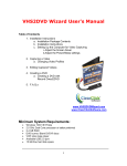
1
3x5 Component Video/Digital Audio Matrix
Switch w/RS-232
Model: 40973
Operation Manual ver.1.0
Table of Contents
Functions ………………………………………………………………………….1
Package Contents………………………………………………………………...1
Features……………………………………………………………………………2
Connecting Devices…….………………………………………………………2-3
Operating the Switch
Controlling the Switch from the IR Remote…………………………….4
Controlling the Switch from the Front Panel………….………………..5
Connecting the Mounting Brackets……………………………………………..6
RS-232 Control……………………………………………………………………6
Factory Default Settings………………………………………………………….7
Replaceable Parts………………………………………………….……………..7
Troubleshooting…………………………………………………………………...7
Specifications……………………………………………………………………...8
Warranty/Important Safety Information………………………………………....9
ii
Operation Manual
3x5 Component Video/Digital Audio Matrix
Switch w/RS-232
Model: 40973
Thank you for purchasing the Deluxe Component Video/Digital Audio 3 In / 5 Out Matrix Switch.
This Matrix Switch allows you to connect up to three audio and video components to five
televisions or monitors.
We recommend that you read this manual thoroughly and retain for future reference.
Function:
The 40973 allows you to route any of three source device outputs to any of five TV/Monitors
You can also route the same output to all TV/Monitors. This switch supports a range of video
resolutions (480i, 480p, 720p, 1080i, and 1080p) to meet the needs of standard and high
definition video/audio equipment. This matrix switch allows you to treat each output as a
separate “zone”. For example, Output 1 can be designated as the home theater zone, and
Output 2 can be the master bedroom zone. This will allow you to, for example, play a video
game in the living room and at the same time watch a high-definition cable/satellite broadcast in
the bedroom. The RS-232 control enables you to program the switch to work with an
automated remote control system.
Package Contents
•
•
•
•
Matrix Switch (1)
Remote Control (1)
Universal Mounting Brackets w/screws (1 set)
User Manual (1)
1
Features:
•
Five Component Video / TOSLINK Outputs
High quality audio and video output to as many as five A/V devices such as TV displays,
A/V receivers or other A/V devices
•
Component Video Inputs
High quality video support for up to three standard or high-definition sources
•
TOSLINK Inputs
Digital multi-channel support for up to three audio sources
•
Standard Stereo RCA Connectors
Left/right stereo audio support for two-speaker systems
•
Push-Button Source Selection
Front panel buttons with tri-color LED for quick input/output identification.
•
Slim Line Remote Control
Operates the switch from a distance or program commands into your existing remote
control system
•
RS-232 Control
PC Interface for optional use with an automated remote control system
Connecting Devices:
For optimal performance, use high-quality audio and video cables. Use a component video
cable with RCA plugs (not supplied) for all component video connections. Use audio cables with
TOSLINK or RCA plugs (not included) for all audio connections.
The switch’s color-coded jacks make it simple to connect devices to the switch. Green – blue
– red jacks (marked as Y, Pb and Pr) are used for component video, red jacks are for right
channel audio and white jacks for left channel audio.
Before connecting the switch to your digital audio equipment, make sure you perform the
following tasks:
•
Power down all components that will be connected to this switch
z
Remove the plastic plug that protects the switch’s TOSLINK jack from dust. Keep plastic
plug for future use.
z
Remove the cable end protectors from the TOSLINK connector on your TOSLINK cable (not
supplied).
2
Follow these steps to connect the components to the switch.
1.
Connect each of the component video outputs from your devices (DVD player, HD
cable/satellite receiver, video game player, etc.) to a set of Inputs 1-3 (Y, Pb and Pr jacks)
on the back or front of the switch.
2.
Connect your devices’ TOSLINK outputs to a TOSLINK Input (1-3) jacks on the back or on
front of the switch. If a device does not have a TOSLINK output, connect its stereo L/R
audio outputs to a set of stereo L/R audio Inputs (1-2) jacks on the back of the switch.
Front panel Input 3 features 3.5mm jack for stereo L/R connections. A 3.5mm to RCA “Y”
adapter (not included) must be used for this connection.
Note: This device does not convert TOSLINK to analog audio or analog audio to
TOSLINK. Audio switching follows video.
3.
Connect component video Outputs (1-5) Y, Pb and Pr of the matrix switch to the
component video inputs of up to five TVs/monitors.
4.
Using a TOSLINK cable, connect the ends from the TOSLINK Outputs (1-5) on the switch
to the TOSLINK inputs on up to five A/V receivers (or digital audio recorders). If devices
do not have TOSLINK inputs, use RCA audio cables to connect from the matrix switch’s
L/R audio Output (1-5) to RCA L/R audio inputs on five displays or A/V receivers.
Example diagram:
Rear Panel
Front Input
3
Operating the Switch:
Controlling the switch with the infrared remote control
1.
Press POWER ON to turn on the matrix switch.
2.
Press 1 – 5 on either the green, red, or orange panels to change the video display of the
device you are using. Green panel represents Input 1. Red panel represents Input 2.
The orange panel represents Input 3.
Example 1 – You would like to route your DVD player on Input
3 to Output 1. Press the number 3 button on the Output 1
row. The LED of Output 1 on the front panel of the switch will
be illuminated orange.
Example 2 – You would like to route your game console on
Input 1 to Output 2, but continue watching the DVD movie
from example 1. Press 1 on Output 2 row. The LED of
Output 2 on the front panel of the switch will be illuminated
green.
Example 3 – You wish to now route your cable box connected
to Input 2 to the displays of both Output 1 and Output 2 at the
same time. Press 2 on Output 1 row, and then press 2 on
Output 2 row. The LED of Output 1 and 2 on the front panel
of the switch will be illuminated red.
Green
Panel
Red
Panel
Orange
Panel
4
Controlling the switch from the front panel
1.
Press POWER button to turn on the switch.
2.
Press the MODE button to select input mode for all Outputs.
- If the MODE switch is illuminated green,
Outputs 1-5 will display the image and sound from Input 1.
- If the MODE switch is illuminated red,
Outputs 1-5 will display the image and sound from Input 2.
- If the MODE switch is illuminated orange,
Outputs 1-5 will display the image and sound from Input 3.
Power Button
Turns the matrix
switch on and off
3.
Mode Button
Outputs (1-5) Buttons
Allows front panel
switching between
output displays
Allows front panel
switching between
inputs
Press the Outputs 1-5 buttons on the front of the switch to toggle between the Inputs 1-3
that are being used by your devices.
Example 1 – You would like to route your DVD player connected to Input 3 to Output 1.
Press the Output 1 button until it is illuminated orange.
Example 2 – You would like to route your game console connected to Input 1 to Output 2,
but would like to continue watching the DVD movie from example 1. Press the Output 2
button until it is illuminated green.
Example 3 – You wish to now route materials from your cable box connected to Input 2 to
both displays connected to Output 1 and Output 2. Press the Output 1 button until it is
illuminated red, and repeat for the Output 2.
5
Connecting the Mounting Brackets
If you have a mounting rack you can use the mounting brackets to mount the matrix switch.
There is a left side bracket and a right side bracket. Please do the following to assemble:
1. Unscrew the two side screws on each side of the Matrix Switch.
2. Unpack the screws from the bag, and identify the smaller screws.
3. Place the mounting brackets on the side of the Matrix Switch so that the two larger holes
on the brackets are aligned with the front of the Matrix Switch, and screw the smaller
screws that were included in the pack on the side of the switch.
4. Using the larger screws that are included in the pack, mount the brackets on your
mounting rack.
RS-232 Control
The Matrix Switch can be controlled by sending command from PC or other equipment. PC and
other equipment can also get the status of the Matrix Switch from the RS-232. Connection
between the Matrix Switch and a PC should be done using a null modem DB9 cable no longer
than 15 meters (50 ft.)
Below in Table 1 is a list of command/status parameters for the Matrix Switch Protocol.
Direction*
Command
Status
0
0x01
Switch Control
0
0x02
0
0
0
0x03
0x04
0x05
0
1
0x06
Inquiry Switch
Status
Power On Device
Power Off Device
Inquiry Power
Status
Sync One Shot
Report Switch
Status
Report Power On
Status
Report Power Off
Status
Report Sync Status
0x21
1
0x23
1
0x24
1
0x26
Table 1. Command/Status
Description
Input
select
Input
select
0
0
0
0
Output
channel
Output
channel**
Output
channel***
0
0
0
0
Input
select
0
0
Output
channel**
0
0
0
sync
0
*Note 1
D=0 indicates transmission from a PC to the Matrix Switch
D=1 indicates transmission from the Matrix Switch to the PC
**Note 2
Output channel = 0 when all outputs are switched to the same input channel
simultaneously
***Note 3
Output channel = 0 when inquiry sync status
6
Note
Note
2
Note
3
Note
2
There are two transmission characters in one transfer packet. The first character includes a
transmission direction byte and command/status code. The second character includes the
parameters of the first character, which carry output channels and input selection information.
Below, Table 2 shows the Matrix Switch control transfer into an automated remote system.
Out 1
Out 2
In 1 1st byte
0x01
0x01
2nd byte
0x91
0x92
In 2 1st byte
0x01
0x01
2nd byte
0xA1
0xA1
In 3 1st byte
0x01
0x01
2nd byte
0xB1
0xB1
Table 2. Matrix Switch Control Transfer
Out 3
0x01
0x93
0x01
0xA3
0x01
0xB3
Out 4
0x01
0x94
0x01
0xA4
0x01
0xB4
Out 5
0x01
0x95
0x01
0xA5
0x01
0xB5
Software is available for download to operate from IBM compatible PCs. View our website for
more information, www.cablestogo.com.
Factory Default Settings:
The 40973 will retain input/output settings when powered off by the remote control or the switch’s
front face power button.
Unplugging the supplied power adapter from the switch, will automatically restore the factory
default setting.
Replaceable Parts
•
•
In the event of a lost or damage part, the
following replaceable accessories are
available. Please call 877-AV-EXPERT
for order information.
98012-AC Adapter
98027-IR Remote Control
Troubleshooting
Problem
No picture
Possible Solution
•
•
•
No sound
•
•
Make sure all connections are secure
Check the front panel of the switch to see if
the proper input by color code has been
selected
Make sure proper component output is
selected on your devices
Make sure all connections are secure
Make sure a digital connection is selected on
your audio equipment if you are using the
TOSLINK outputs
7
Specifications:
Interface
Inputs
Video: Component
Video (3)
Audio: TOSLINK (3)
L/R Audio RCA
(2)
L/R Audio
3.5mm (1)
Outputs
Video: Component
Video (5)
Audio: TOSLINK (5)
L/R Audio (5)
RS-232 (1)
75Ω
Video Component Input
Impedance
Video Bandwidth
TOSLINK Output Level
-3dB@300MHz
6uW Min.
Sampling frequency
Power Requirement
44.1K Hz
DC 12V 500mA (Using the Supplied AC Adapter)
Power
Weight
Dimensions (W x H x D)
6 Watts
4 lbs.
2.63 x 13.58 x 6.89 in.
8
Impact Acoustics™ One Year Warranty
At Impact Acoustics, we want you to be totally confident in your purchase. That is why we offer a
one year warranty on this device. If you experience problems due to workmanship or material
defect for the duration of this warranty, we will repair or replace this device. To request a Return
Merchandise Authorization (RMA) number, contact customer service at 877-AV-EXPERT or
www.impactacoustics.com.
Important Safety Information
!
Do not plug the switch adapter in any outlet that does not have enough current to allow the
switch to function. Refer to the specifications in this manual for power level of the switcher.
! Liquid:
If your switch or its corresponding power adapter has had liquid spilled on or in it, do not
attempt to use the unit.
Do not attempt to use this product in an outdoor environment as elements such as rain, snow,
hail, etc. can damage the product.
! In case of a storm, it is recommended that you unplug this device from the outlet.
! Avoid placing this product next to objects that produce heat such as portable heaters, space
heaters, or heating ducts.
! THERE ARE NO USER SERVICEABLE PARTS
Do not attempt to open this product and expose the internal circuitry. If you feel that the
product is defective, unplug the unit and refer to the warranty information section of this
manual.
Impact Acoustics™
3555 Kettering Blvd.
Moraine, OH 45439
Tech Support: 877-AV-EXPERT
www.impactacoustics.com
9