1
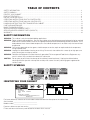
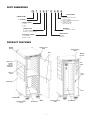
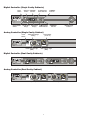
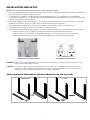
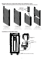
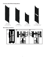
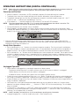
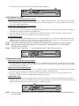
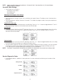
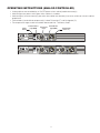
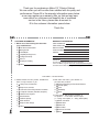
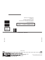
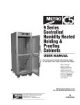
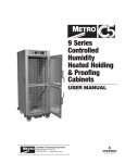
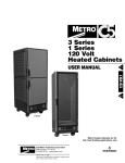
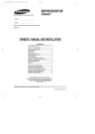
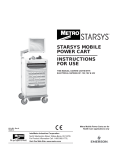
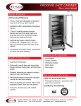
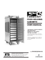
T-SERIES HOT
FOOD HOLDING
CABINETS
USER MANUAL
THIS MANUAL COVERS CABINETS
WITH ELECTRICAL
RATINGS OF: 120V 1400W &
220-240V 1176-1400W
When ordering electrical parts, always confirm the rating listed on cabinet data plate on
back of cabinet.
Differences in voltage, amps or wattage are
listed with BOLD TEXT in replacement part
descriptions.
Metro Heated Cabinets are for
Hot Food Holding applications only
InterMetro Industries Corporation
North Washington Street, Wilkes-Barre, PA 18705
For Product Information Call: 1-800-992-1776,
Visit Our Web Site: www.metro.com
TABLE OF CONTENTS
SAFETY INFORMATION ..................................................................................................................................................... 2
SAFETY SYMBOLS ............................................................................................................................................................. 2
IDENTIFY YOUR CABINET ................................................................................................................................................. 2
PRODUCT FEATURES ....................................................................................................................................................... 3
INSTALLATION AND SETUP .............................................................................................................................................. 5
OPERATING INSTRUCTIONS (DIGITAL CONTROLLER) .................................................................................................. 8
OPERATING INSTRUCTIONS (ANALOG CONTROLLER) ................................................................................................. 11
HANDLING INSTRUCTIONS FOR TRANSPORTING CABINET ......................................................................................... 12
CARE AND MAINTENANCE ............................................................................................................................................... 12
BASIC TROUBLESHOOTING ............................................................................................................................................. 13
SERVICE AND REPLACEMENT PARTS ............................................................................................................................. 14
SERVICE AND REPLACEMENT PARTS (CIRCUITS) ......................................................................................................... 18
WARRANTY ........................................................................................................................................................................ 22
SAFETY INFORMATION
WARNING: This cabinet is only for hot food holding applications.
WARNING: Follow all food safety guidelines. Pre-heat the cabinet to the desired temperature before placing hot cooked
food into the cabinet. Food must be at the appropriate temperature before being placed into cabinet. Use a
food probe to check internal food temperature - the cabinet temperature is not necessarily the internal food
temperature.
WARNING: Only factory approved service agents should attempt to service, repair or replace electrical components,
wiring or power cord.
WARNING: Unplug the cabinet before cleaning or servicing. Do not wash the cabinet with a water jet or high pressure
water, do not hose wash/spray interior.
WARNING: Food Service Equipment must be electrically grounded. Failure to ground Food Service Equipment may
result in serious injury or death from electrical malfunction.
CAUTION: Do not spray or pour water into the top of the cabinet (control enclosure). Unplug the cabinet before
cleaning and then wipe with a damp cloth and dry with a towel. Use only cleaning agents approved for
stainless steel.
SAFETY SYMBOLS
IDENTIFYING YOUR CABINET
®
®
C
®
US
LISTED 465C
MODEL NO.
C5TX-XXXX
XXXV XXHZ
XXXXXW
01/11
SERIAL NO. C5TXXXX
INTERMETRO INDUSTRIES CORP., WILKES-BARRE, PA 18705
WWW.METRO.COM
For future reference, note the serial and model number found on the data plate of the cabinet here:
Serial number ________________________________
Model number ________________________________
Date the cabinet was put into service _______________________________
Fill out and return the warranty card located at the back of this manual.
2
PART NUMBERING
C5
9 D
_ B
_ A
_
_ - D
_ X
_ S
_ _
__ T
ACCESSORIES
CABINET NAME
SLIDES
L = ADJUSTABLE LIP LOAD
18x26 & 12x20
B = ADJUSTABLE BOTTOM LOAD
18x26 & 12x20
F = FIXED LIP LOAD
GN & 12x20 only
T = T-SERIES
CABINET HEIGHT
9 = FULL
8 = 5/6
5 = 1/2
MATERIAL
S = STAINLESS STEEL
CABINET TYPE
D = DUAL CAVITY
BLANK = SINGLE CAVITY
CONTROLLER
DIGITAL
ANALOG
ELECTRICAL RATING
X = 220-240V
BLANK = 120V
PRODUCT FEATURES
Molded
Handle
Digital Control
Panel
Analog Control
Panel
Door
Molded
Corners
Rear Push
Handle
(not on
1/2 Height
Cabinets)
Info
Panel
Armour
Panel
Door
Latch
Shell Body
Door
Strip Bumper
(2) Brake Caster
- Front
(2) Swivel Caster
- Rear
Slides
Air Chimney
3
Air Chimney
Digital Controller (Single Cavity Cabinets)
Power
Switch
Settings/Enter
Switch
Selection HEAT OFF
Switch
Indicator
HI Temperature
Alarm Indicator
Temperature Temperature
Range
Display
ELEMENT
Indicator
LO Temperature
Alarm Indicator
PREHEAT
Indicator
Battery Charge
Indicator
Analog Controller (Single Cavity Cabinet)
Power
Switch
Temperature Range
Setting
Power Indicator Light
(RED)
Thermometer
(°F and °C)
Heat Indicator Light
(RED)
Digital Controller (Dual Cavity Cabinets)
Bottom Compartment Controller
Top Compartment Controller
Analog Controller (Dual Cavity Cabinet)
Top Compartment Controller
4
Bottom Compartment Controller
INSTALLATION AND SETUP
NOTE: The First 4 steps below are common to both Analog and Digital cabinets.
1. Check for Shipping Damage: Check the packaging and cabinet for shipping damage before and after unloading the
unit, and after removing all packaging materials.
2. The receiver of this product is responsible for filing freight damage claims. This equipment must be opened
immediately for inspection. All visible damage must be reported to the freight company within 48 hours and must be
noted on freight bill at the time of delivery.
3. Concealed damage is your responsibility — you must advise the carrier of any loss or damage within 15 days after
receipt of the cabinet. If there is damage, retain the original packaging for inspectors.
4. After unpacking the cabinet, remove all packing material from the inside as well as outside of the unit.
5. The power cord is located at the back of the cabinet as shown in Figure 1.
6. Refer to the data plate located near the power cord for the electrical specifications of cabinet as shown in Figure 2.
With the POWER switch OFF, plug the cord into the appropriate rated, grounded receptacle.
Cabinets rated at 120V 1400W must be plugged into either a 15 amp or 20 amp 125 VAC receptacle.
Cabinets rated at 220-240V 1176-1400W must be plugged into a 15 amp 250 VAC receptacle.
FIGURE 1:
POWER CORD LOCATION ON CABINET
FIGURE 2:
C5 T-SERIES WALL RECEPTACLES
WARNING: Do not allow combustible materials to be stored or accumulate on, under or next to the cabinet. Do not
block any ventilation louvers or slots.
CAUTION: C5 T-Series cabinets (Polymer Armour panels on the sides) must not be placed next to char broilers
or Allow 18" (46cm) between the Armour panels and any cooking equipment. Do not allow hot kitchen
equipment whose surfaces exceed 200°F (90°C) to touch the panels.
Slide Installation Adjustable on Uprights (Bottom Load and Lip Load)
BOTTOM LOAD
LIP LOAD
5
Maximum Capacity of Adjustable Slides (Lip and Bottom Loads)
NOTE: Only lip load capacities are shown below. Bottom loads have the same capacities.
SiteSelect™
feature make
slide installation
easier.
FULL HEIGHT SINGLE
16 Levels
Position from Bottom
5/6 HEIGHT CABINET
14 Levels
Position from Bottom
1/2 HEIGHT CABINET
9 Levels
Position from Bottom
Lip Load Part No. C5T-LL-9, 1PR
Bottom Load Part No. C5T-BL-9, 1PR
Lip Load Part No. C5T-LL-8, 1PR
Bottom Load Part No. C5T-BL-8, 1PR
Lip Load Part No. C5T-LL-5, 1PR
Bottom Load Part No. C5T-BL-5, 1PR
DUAL CAVITY
7 Levels (14 Total)
Position from Bottom
Lip Load Part No. C5TD-LL-9, 2PR
Bottom Load Part No. C5TD-BL-5, 2PR
Installation of Fixed Slide Racks
B
Top Mounting
Bracket
Fixed Slide
A
Bottom Mounting
Bracket
NOTE: Door not shown for clarity.
6
Fixed Lip Load Slide Configurations
FULL HEIGHT
1-Piece Construction
Part No. C5T-FS-9, 1PR
1/2 HEIGHT
1-Piece Construction
Part No. C5T-FS-5, 1PR
5/6 HEIGHT
1-Piece Construction
Part No. C5T-FS-8, 1PR
DUAL CAVITY
1-Piece Construction (2 Pairs)
Part No. C5TD-FS-9, 2PR
Wire Shelf Installation
1
2
Insert left side of wireshelf into upright at
an angle and then lower right side to level
and shift shelf to fit into right side upright.
WireShelf
7
3
NOTE: Wireshelf must be used with
cabinet uprights
OPERATING INSTRUCTIONS (DIGITAL CONTROLLER)
NOTE:
Before using your cabinet for the first time, heat the cabinet to maximum temperature for 15 minutes to burn off
oils on stainless from manufacturing process. During this process slight smoke may be seen.
Power-Up and Pre-Heat
• When the cabinet is switched on, all LEDs and display segments illuminate (blinking) for 3 seconds.
• The display then shows the set point (blinking) for 3 seconds, followed by current temperature.
• The preheat indicator light turns off after the temperature set point is reached. Set point range is 85 – 200 °F
(29-93 °C) and “---” indicates one step below 85 °F (29 °C).
• If the set point is “---” (heat off) the pre heat LED will be off. The “heat off” LED will be on.
NOTE: The current temperature scale LED (°F or °C) remains illuminated whenever the cabinet is turned on. The
“element indicator” LED remains on whenever the circuit is energized.
• During initial pre-heat, the “lo temp” alarm is disabled.
• When plugged in and powered-on, the “Power” display shows the current charge status of the battery. When
charging, the uppermost led blinks in 1 second intervals, while all LEDs below it remain on continuously. When the
battery is fully charged, all power LEDs are lit continuously.
1. Allow the cabinet to pre-heat without food for 30 minutes to an hour. The pre-heat time required to reach the
temperature set point is dependent on the set point, the size of the cabinet, the door type (single or dual) and the
temperature of the room the cabinet is in.
Steady State Operation
• Press and release the “+ or –” buttons at any time to change the set points. The first push recalls and displays
the current set point. If a button is pressed again within a 4 second period, the set point will be changed by a 1
degree increment. The set point will be displayed for 4 seconds, then shows the current temperature display.
• Press and hold the “+ or –” buttons to recall and display the current set point for 4 seconds. The set point will then
change in 1 degree increments every ½ second for the first 5 seconds, then increase in 10 degree increments
every ½ second until the button is released. The set point will be displayed for 4 seconds, then shows the current
temperature display.
Unplugged Operation
• When cabinet is unplugged the system begins operation on battery power.
Temperature monitoring and air circulation continues up to (3 hours) after the cabinet is un-plugged.
Cabinet displays are turned on when the cabinet is unplugged.
If additional runtime is desired, press power switch to engage controller and fan.
• Display the current cabinet temperature: Press the “+ or –” button. The display will show the current temperature
for as long as the button is depressed. Temperature set points cannot be changed while cabinet is unplugged.
• Display the battery charge status: Press the “battery” button. The display will show the current charge level for as
long as the button is depressed.
• Low Temp Alarm: If the cabinet temperature drops below the alarm set point for more than 5 minutes during
operation, the display will begin to blink “___”, and the “LO TEMP” LED will illuminate (blinking). This will repeat
every 10 seconds.
• Hi Temp Alarm: If the cabinet is in “HEAT OFF” mode and the temperature rises above the alarm set point for
more than 5 minutes during operation, the display will begin to blink “---”, and the “HI TEMP” LED will illuminate
(blinking). This will repeat every 10 seconds.
NOTE: Audio (if enabled), Low temp Alarm: (3) 1/2 second beeps, repeating every 10 seconds.
• Average charging time = 1 hour for single cavity and 11/2 hours for dual cavity.
8
• The cabinet will charge any time, when the power cord is plugged-in.
Low Temperature Alarm
Checking the low temperature alarm set point
• Press and hold the “Settings” button, followed by the “-” button, then release both. The display shows the current
low temperature alarm set point and illuminates the LO TEMP led (blinking) for 5 seconds, before again showing
the current cabinet temperature.
Changing the low temperature alarm set point
• Perform the step listed above.
• Press the “+ or –” buttons within the 5 second period to change the alarm set point. (the same rules that apply to
changing the temperature set points also apply here).
• Press the “Settings” button to save the new alarm set point and exit this function, or after 5 seconds with no
buttons pressed, the new alarm set point will be automatically saved.
Low temperature alarm
• If the cabinet temperature drops below the alarm set point for more than 5 minutes during operation, the display
will begin to blink, and the “LO TEMP” LED will illuminate (blinking). This will continue until the temperature rises
above the low temp set point or the low temp alarm set point is lowered.
NOTE: If the cabinet operating temperature is set below the low temperature alarm setting, the alarm is disabled.
NOTE: Audio (if enabled), button press produces a 1/4 second “chirp”. Low temp Alarm: (3) 1/2 second beeps,
repeating every 10 seconds.
NOTE: Set point range is 135–185 °F “---” (off) one step below 135 °F. Default set point is 140 °F
Hi Temperature Alarm
Checking the Hi temperature alarm set point:
• Press and hold the “Settings” button, followed by the “+” button, then release both. The display shows the current
hi temperature alarm set point and illuminates the “HI TEMP” LED (blinking) for 5 seconds, before again showing
the current cabinet temperature.
Changing the Hi Temp Alarm set point
• Perform the step listed above. Press the “+ or –” buttons within the 5 second period to change the alarm set point.
( the same rules that apply to changing the temperature set points also apply here).
• Press the “Settings” button to save the new alarm set point and exit this function, or after 5 seconds with no
buttons pressed, the new alarm set point will be automatically saved.
Hi temperature alarm
• If the cabinet temperature rises above the alarm set point for more than 5 minutes during operation, the display
will begin to blink, and the “HIGH TEMP” LED will illuminate (blinking). This will continue until the temperature rises
above the low temp set point or the low temp alarm set point is lowered.
NOTE:
This alarm is for ambient holding (HEAT OFF) applications. If the cabinet is operating in hot holding mode, this
alarm is disabled.
9
NOTE:
Audio (if enabled), Button press produces a 1/4 second “chirp”. Low temp Alarm: (3) 1/2 second beeps,
repeating every 10 seconds.
Controller User Settings
• User settings are classified as:
Temperature Scale Mode
Sound Mode and
Lock-out Mode
Modifying the Controller’s User Settings
• Turn the cabinet OFF.
• Press and hold the “Settings” button. Press and release the “power” button. The display shows 3 horizontal bars
(blinking).
• Continue holding the “Settings” button for 5 seconds. This enables the program mode, starting with temperature
scale selection.
Temperature scale mode
• The display will show only the temperature scale (blinking). Press the “+ or –” button to toggle between °F and °C.
Press the “Settings” button to save and advance to the Sound mode.
Sound mode
• The display shows “Snd On or Snd OFF” (blinking). Press the “+ or –” button to toggle between them (this setting
will always default to the setting that it had previously been set to). Press the “Settings” button to save and
advance to the Lockout mode.
Lock-out mode
• The display shows “LOC On or LOC OFF” (blinking). Press the “+ or –” button to toggle between them (this setting
will always default to the setting that it had previously been set to).
• Lock-out mode will prevent users from accidentally changing temperature and alarm settings. If the user attempts
to change the settings of the cabinet while the control lock-out is enabled, the temperature display will show
“LOC” (blinking) for 4 seconds before again displaying the current conditions.
NOTE: If no buttons are pressed for 20 seconds, the controller will automatically save and exit user settings mode.
Service Diagnostic Codes
• If the controller detects a problem in heating element, fan motor, or battery the following service codes will be
displayed:
Heating Element
Fan Motor
Battery
Temperature Sensor
10
OPERATING INSTRUCTIONS (ANALOG CONTROLLER)
• Analog cabinets are controlled by an ON/OFF power switch and adjustable thermostat(s).
• Indicator light near power switch glows when cabinet is turned on.
• Indicator light(s) near thermostat(s) glow when the cabinet heat element(s) are on to achieve or maintain cabinet
temperature.
• Thermometer(s) read cabinet temperature(s) in both Fahrenheit (ºF) and Centigrade (ºC).
• The temperature range can be increased or decreased with “Thermostat Knob”.
Power
Switch
Power Indicator
Light (RED)
Thermostat
Knob
Heat Indicator
Light (RED)
Top Compartment Contoller
11
Thermometer
(°F and °C)
Bottom Compartment Contoller
HANDLING INSTRUCTIONS FOR TRANSPORTING CABINETS
• Always assure brakes are set in OFF position prior to moving cabinet.
• Assure door(s) is fully closed and travel latch (if equiped) is engaged.
• Push/Pull cabinets by the push / pull handles located on the back of the cabinet
(not included on 1/2 ht models) or by the molded handles on front side of the
armour panel.
• Always keep a firm grip on handles while cabinet is in motion.
• Ergonomic handles and bumpers are provided as grab points for easy handling while pushing, pulling and
crossing thresholds, place your foot onto one of the bottom handles while pulling on the top handles (only pull
enough to reduce the weight on the casters and to clear the obstacle).
• Arrange multiple cabinets close together (handle to handle) in transport vehicle.
• Never strap or band any cabinet over the top or the control panels as this may damage the electrical components.
• Apply brakes when cabinet is in transport vehicle.
• Strap/band cabinets across mid section and assure the straps are securely fastened to vehicle walls.
• When lowering on lift gate, apply caster brakes and pay attention that the cabinet does not move off the lift gate.
Keep a firm grip on cabinet when lowering.
CARE AND MAINTENANCE
Before proceeding with any maintenance activity strictly follow “Safety
Information” on page 2 of this manual.
Cleaning The Cabinet
WARNING: Unplug the cabinet before cleaning or servicing. Do not wash the cabinet with a water jet or high pressure
water.
CAUTION: Do not spray or pour water into the control enclosure. To clean the cabinet, wipe with a damp cloth and dry
with a towel. Use only cleaning agents approved for stainless steel.
CAUTION: Do not use cleaners with chlorides or phosphates as they may cause damage to stainless steel.
1. Make certain that the cabinet has cooled down before cleaning. Use cleaners in the proper concentrations. Follow
the manufacturer’s directions for the cleaning product used. The floor of the cabinet may be hosed out with low
pressure water. After using any cleaning products, thoroughly rinse all surfaces to remove residue.
2. Use a damp cloth or sponge. Mild soap suitable for stainless steel is acceptable. Dry with a clean towel. Wipe up
spills as soon as possible and regularly clean the cabinet to avoid staining and difficult to clean conditions.
Cabinet Maintenance — All Models
C5 T-Series cabinets have been designed to require very little maintenance. With normal use, cleaning is the only form
of maintenance that need to be done on a regular basis. Keeping the casters free of dirt build-up will go a long way in
prolonging their life.
Regularly inspect the casters. Tighten loose fasteners and replace worn or
damaged parts with new InterMetro approved parts. Replace worn or damaged
casters immediately; lubricate casters regularly.
Top Module Maintenance
The module of the cabinet has also been designed to require very little maintenance. With normal use, cleaning is the
only form of maintenance that needs to be done on a regular basis.
Battery Care (Digital Cabinet Only)
• Keep the battery clean, dry and free of electrolyte and corrosion residue.
• Ensure wire connections and battery strap are tight.
12
BASIC TROUBLESHOOTING
WARNING: Only factory approved service agents should attempt to service, repair or replace electrical
components, wiring or power cord.
1. Controls do not work (no display or indicator lights):
• Check that the cabinet is plugged-in.
• Check that the outlet has power.
• Check that the power switch is in the “On” position.
• Check the cabinet wiring from the power cord to the power switch and to the controller.
• Controller is faulty.
2. Controller temperature display does not change (displays a constant value approximately equal to the
minimum or maximum of the set point temperature range, 85°F (29°C) or 200°F (93°C):
a. The temperature sensor and controller are not communicating:
• Controller needs to be replaced.
• Temperature sensor needs to be replaced.
3. Temperature too hot:
a. During initial pre-heat, cabinet may overshoot set point.
b. If displayed temperature exceeds 220°F (104°C):
• Blower wiring is faulty or disconnected. Blower needs replacing.
• The thermostat may have failed and the thermal cut-out device is controlling the temperature.
• Thermal cut-out device may have failed.
c. Digital control: Refer to page 9 section - ”High Temperature Alarm” for changing the set point temperature.
4. Temperature too low:
a. The cabinet may still be in pre-heat or recovering from the door being opened.
b. Door(s) is not closed or sealing properly.
c. Worn out door gaskets. Replace gaskets.
d. Blower is not circulating air:
• Blower wiring is faulty or disconnected.
e. Refer to page 9 section - “low Temperature Alarm” for changing the set point temperature.
5. No heat generated
a. If the heat indicator light is on but the cabinet does not draw approximately 12 amps for 120V 1400W units and 8
amps for 220-240V 1176-1400W
• Air heater element may be faulty.
• The wiring to the air heater element may be faulty or disconnected.
• The controller (air heater relay) may be faulty.
b. If the heat indicator light does not come on, the controller may be faulty.
6. Display problems in cabinets:
• Refer to page 10 section - “Service Diagnostic Codes”.
13
SERVICE AND REPLACEMENT PARTS
WARNING: Only factory approved service agents should attempt to service, repair or replace electrical components,
wiring or power cord.
Cabinet, Door and Electrical Parts
ITEM #
1
2
3A
3B
4
Replacement
Part No.
Description
Replacement
Part No.
C5T-FS-5
1/2 HT CABINET FIXED SLIDES — 1 PR.
Description
26
RP-WHITEBRD
WHITE BOARD WITH CLIPS
C5T-FS-8
5/6 HT CABINET FIXED SLIDES — 1 PR.
27
RPC06-746
KNOB, ANALOG
C5TD-FS-9
DUAL CAVITY CABINET FIXED SLIDES — 2 PR.
28
RPC13-083*
STRAIN RELIEF
C5T-FS-9
TALL CABINET FIXED SLIDES — 1 PR.
29
RPC13-085*
WIRE JOINT, SET SCREW TYPE, ANALOG (NOT SHOWN)
C5T-SHELF
WIRE SHELF (MUST BE USED WITH RACK UPRIGHTS)
30
RPC13-096*
TERMINAL BLOCK
RPC6P
6" CASTER, SWIVEL
31
RPC13-198
THERMAL CUT OUT
RPC5P
5" CASTER, SWIVEL
32
RPC6PB
6" CASTER, BRAKE
RPC5PB
5" CASTER, BRAKE
RPC06-1011A
TALL CABINET DOOR GASKET
RPC06-1011B
5/6 HT CABINET DOOR GASKET
RPC06-1011C
1/2 HT CABINET DOOR GASKET
ITEM #
33
RPC13-218
SGL CAVITY THERMOMETER, ANALOG
RPC13-446
DUAL CAVITY THERMOMETER, ANALOG
RPC13-234
SGL CAVITY THERMOSTAT, ANALOG
RPC13-447
DUAL CAVITY THERMOSTAT, ANALOG
34
RPC13-246
RED INDICATOR LIGHT, ANALOG CABINET
35
RPC13-375
MASTER SWITCH, ANALOG CABINET
36
RPC06-1011D
DUAL CAVITY DOOR GASKET
RPC13-440
125V 15A COIL POWER CORD, RT. ANGLE PLUG
5
RPC06-1039
SNAP BUSHING, .750"
RPC13-546
125V 15A COIL POWER CORD, STR. PLUG
6
RPC06-189
SNAP BUSHING, 1"
RPC13-537
250V 15A COIL POWER CORD, EXPORT
7
RPC07-055
BULB COVER GROMMET, DUAL CAVITY
RPC13-421
120V AC BLOWER, IMPELLER AND LH NUT — ANALOG
8
RPC11-446
REAR HANDLE
9
RPC5T-5UPRT
1/2 HT CABINET RACK UPRIGHT — 1 PR.
37
38
RPC13-509
220-240V AC BLOWER, IMPELLER AND NUT — EXPORT
RPC13-423
CONTROLLER, DIGITAL
RPC5T-8UPRT
5/6 HT CABINET RACK UPRIGHT — 1 PR.
39
RPC13-424
BATTERY GAUGE, DIGITAL
RPC5T-9DUPRT
DUAL CAVITY CABINET RACK UPRIGHT — 1 PR.
40
RPC13-438
MOTOR RELAY, DIGITAL
RPC5T-9UPRT
TALL CABINET RACK UPRIGHT — 1 PR.
41
RPC5TD-SNR
DIGITAL TEMP SENSOR AND HARDWARE
10
RPC5T-ARMR-RD
MOLDED ARMOUR PANEL, RED WITH HARDWARE
42
RPC13-442
DUAL CAVITY WIRE HARNESS, DIGITAL
11
RPC5T-BMPR
STRIP BUMPER WITH INSERT AND SCREWS
RPC13-560
SGL CAVITY WIRE HARNESS, DIGITAL
12
C5T-BOTLD
BOTTOM LOAD SLIDE — 1 PR.
13
RPC5T-CABPKT
CABINET DOOR POCKET
14
RPC5T-CRN
TOP MOLDED CORNER
15
RPC5T-DRSTKR
DOOR STRIKE PLATE
43
44
RPC13-451
120V 1350W, HEAT ELEMENT, SGL. CAVITY
RPC13-510
240V 1350W, HEAT ELEMENT, EXPORT SGL. CAVITY
RPC13-501
120V 675W, HEAT ELEMENT, DUAL CAVITY
RPC13-511
240V 675W, HEAT ELEMENT, EXPORT DUAL CAVITY
16
RPC5T-HDL
MOLDED HANDLE WITH HARDWARE
45
RPC13-503
24V DC MOTOR ASSY., DIGITAL
17
RPC5T-LPLD
LIP LOAD SLIDE — 1 PR.
46
RPC13-507
BATTERY, 12V DC
18
RPCORDCLIP
CORD CLIP WITH HARDWARE
47
RPC13-508
IMPELLER AND LH. NUT
19
RPC06-035
REAR HANDLE CAP
48
RPC13-519
CURRENT SENSOR, DIGITAL
20
RPC06-1032
INFO PANEL EXTRUSION
49
RPC13-521
POWER SUPPLY, DIGITAL
21
RPC14-329
DOOR LATCH
50
RPC13-557
FUSE HOLDER
22
RPC14-330
DOOR HINGE
51
RPC13-588
4A FUSE
23
RPC5T5-DOOR
1/2 HT CABINET COMPLETE DOOR ASSY.
52
RPC5-SCLP
ANALOG BULB CLAMP KIT
RPC5T8-DOOR
5/6 HT CABINET COMPLETE DOOR ASSY.
53
RPC13-502
DC MOTOR CONTROLLER
RPC5T9D-TOPDR
TOP DUAL CAVITY CABINET COMPLETE DOOR ASSY.
54
RPF07-125
UPRIGHT SPRING BUTTON CLIP
RPC5T9D-BOTDR
BOT. DUAL CAVITY CABINET COMPLETE DOOR ASSY.
55
RPC5T-TRVL
TRAVEL LATCH/HSAP AND HARDWARE (NOT SHOWN)
56
C5TINFOLBL-10
INFO PANEL LABELS — 10 PK
RPC5T9-DOOR
TALL CABINET COMPLETE DOOR ASSY.
24
RPC5T-INFO
COMPLETE INFO PANEL ASSY.
25
RPF04-368
BINDING BARREL, DOOR LATCH
14
NOTE:
Some components are common to all cabinets. Certain items are common to both the single
and dual cavity cabinets. Some electrical components are only used on dual cavity units.
Refer to replacement parts list on page 14 and read the descriptions carefully to insure
desired replacement part is ordered. To identify the cabinet model, see page 2.
15
REMOVABLE
ACCESS COVER
REMOVABLE
TOP COVER
28
16
14
18
x4
36
19
10
**
8 **
16
3B
11
3A
CONTROL
PANEL
*
33
THERMOSTAT INSULATION
BRACKET PAD
43
35
*
47
34
34
27
32 *
31
37
ANALOG SINGLE CAVITY CABINET
* * ALL CABINETS EXCEPT 1/2 HT MODELS
AND DUAL CAVITY CABINETS USE DIFFERENT
* SINGLE
ELECTRIC COMPONENTS. REFER TO REPLACEMENT PARTS
LIST FOR DESIRED RP NUMBERS.
16
MOTOR
MOUNTING
BRACKET
18
NOTE:
Several components of digital cabinets are common with analog cabinets. Refer to
replacement parts list on page 14 for details.
17
SERVICE AND REPLACEMENT PARTS (CIRCUITS)
Analog Dual Cavity Cabinet
POWER CORD
21
4
AC BLOWER MOTOR
21
4
C5T SERIES ANALOG DUAL COMPARTMENT CABINET
4
STRAIN RELIEF
10
A
A
GROUND STUD
10
21
10
AIR ELEMENT
BLACK 37"
A
WIRE NUT
THERMAL
CUT OUT
WHITE 46"
BLACK 46"
WHITE
13
13
WIRE NUT
BLACK 50"
3
10
4
AC BLOWER MOTOR
21
4
21
B
B
10
AIR ELEMENT
BLACK 6"
13
B
WHITE 38"
BOTTOM COMPARTMENT
B
BLACK 35"
WHITE 28"
THERMAL
CUT OUT
7
21
7
BLACK 70"
TOP COMPARTMENT
THERMOSTAT &
THERMOSTAT
BULBS
WIRE NUT
7
19
13 7
1
1
20
14 8
2
2
15 9
3
3
20
16 10
4
4
10
BOT COMPARTMENT
THERMOSTAT &
THERMOSTAT
BULBS
BLACK 9"
22
21
22
23
23
17 11
5
5
24
24
18 12
6
6
C C
BLACK 9"
WIRE NUT
14
BLACK 16"
BLACK 24"
56
1
18
BLACK 16"
BLACK 16"
BLACK 16"
BLACK 16"
BLACK 12"
BLACK 16"
12
BLACK 16"
TERMINAL BLOCK
23
2
20
22
12
6
BLACK 16"
23
-
O
MASTER POWER
SWITCH
14
BOT. COMPARTMENT
THERMOMETER
TOP COMPARTMENT
THERMOMETER
BLACK 24"
BLACK
A
GREEN
WHITE 33"
WHITE 37"
BLACK 6"
G
TOP COMPARTMENT
RED
LIGHT
24
TOP COMPARTMENT
THERMOSTAT
RED
LIGHT
18
BOT.COMPARTMENT
THERMOSTAT
18
RED
LIGHT
Digital Dual Cavity Cabinet
45
MTR CNTL
MTR CNTL
40
39
42
41
38
48
53
46
x2
49
19
50 51
Analog Single Cavity Cabinet
POWER CORD
STRAIN RELIEF
4
SINGLE CAVITY ANALOG WIRING DIAGRAM
G
GROUND STUD
21
AC BLOWER MOTOR
5
BLACK 6"
WHITE 46"
9
BLACK 46"
WIRE NUT
WHITE
A
WIRE NUT
BLACK 35"
WHITE 28"
WHITE 38"
AIR ELEMENT
A
1
THERMAL
CUT OUT
BLACK 50"
21
TERMINAL BLOCK
19
20
13 7
14 8
1
2
21
22
23
24
15 9
16 10
17 11
18 12
3
4
5
6
1
2
8
23
24
3
4
5
6
BLACK 16"
BLACK 16"
THERMOSTAT
BULB
THERMOMETER
BULB
CC
BLACK 16"
BLACK 16"
12
BLACK 16"
22
BLACK 12"
23
8
22
6
2
+
23
12
O
MASTER POWER
SWITCH
RED
LIGHT
BLACK 16"
BLACK
GREEN
HEAT
THERMOSTAT
RED
LIGHT
24
20
THERMOMETER
Digital Single Cavity Cabinet
45
MTR CNTL
40
42
41
38
48
53
46
x2
50 51
49
21
Thank you for purchasing a Metro C5 T-Series Cabinet.
We are certain you will be more than satisfied with its quality and
performance. Please fill in the warranty information space below
so we may register your warranty. Also, so that we may learn
more about our customers and hopefully be of continued
service in the future, please take a moment to
fill in the customer information space below.
Thank You
CUSTOMER INFORMATION
1. Which one of the following best describes
your establishment?
a. Full-Service Restaurant
b. Banquet Hall
c. Hotel/ Motel
d. Hospital/ Nursing Home
e. College/University
School
f.
g. Employee Feeding
h. Other
WARRANTY INFORMATION:
Cabinet Model No.
Cabinet Serial No.
Date Purchased
Customer Name
Address
Phone No.
For warranty coverage please fill out this card and
return it to Metro, or go to www.metro.com/heatedcabinetsupport
and select Online Warranty Registration to register electronically.
FOLD HERE — DO NOT DETACH
2. Please indicate the two product benefits that
were of major interest to you.
a.
b.
c.
d.
e.
f.
g.
h.
i.
j.
Heavy Duty Construction
Easy-to-use controls
Foamed in Place Polyurethane Insulation
Transport Features (Handles, Bumpers)
Mobile Power System
Size Selection
Cabinet capacity
Slide selection
Easy-to-clean design
Other
3. Main factor that led to your decision to
pur chase this product?
a. Product operating and functional features
Overall quality
b.
Price
c.
d. Availability
e. Other
4. Three sources that led to the purchase of
his product — in the order of their impact
(1 — being most impact; 3 — being least impact).
a. Trade Journal Ad
Trade Show
b
c. Sales Call
d. Direct Mail
e. Previous Purchase
Other
f.
North Washington Street, Wilkes-Barre, PA USA 18705
1-800-992-1776
www.metro.com
Information and specifications are subject to change
without notice. Please confirm at time of order.
L01-459
L01-459
Rev. B03/11
• 9/12
STAPLE HERE
STAPLE HERE
20
STAPLE HERE
20
STAPLE HERE
FOLD HERE — DO NOT DETACH
NO POSTAGE
NECESSARY
IF MAILED
IN THE
UNITED STATES
B USINESS REPLY MAIL
F I R S T- C L A S S
P E R M I T N O. 1 2 1
W I L K E S - B A R R E , PA
POSTAGE WILL BE PAID BY
INTERMETRO INDUSTRIES CORPORATION
ATTN: CUSTOMER SERVICE
P O BOX A
WILKES-BARRE PA 18705-9968