1
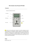
FIA8000 Quantitative Immunoassay Analyzer
User Manual
GeTein BioMedical Inc.
4640 SW Macadam Avenue, Suite 130C;
Portland, OR 97239, USA
Tel: 1-971-407-3868
Fax: 1-971-407-3868
E-mail: [email protected];
[email protected]
Website: http://www.geteinbio.com
Lotus Global Co., Ltd.
15 Alexandra Road London UK NW8 0DP
Tel: 44-20-75868010
Fax: 44-20-79006187
Catalogue
1. Introduction .................................................................................................................................. 1
1.1 Identification ....................................................................................................................... 1
1.2 Product classification .......................................................................................................... 1
1.3 Environment conditions ...................................................................................................... 1
1.4 Intended purpose ................................................................................................................ 1
1.5 Materials required but not provided ................................................................................... 1
2. Principle of measurement ............................................................................................................. 2
2.1 Overview: Running a test .................................................................................................... 2
2.2 Working principle ................................................................................................................ 2
3. Package, appearance and technical specification ......................................................................... 3
3.1 Package................................................................................................................................ 3
3.2 Appearance ......................................................................................................................... 3
3.3 Keypad functions ................................................................................................................. 3
3.4 Technical specification......................................................................................................... 3
4. Performance characteristics .......................................................................................................... 5
4.1 Quality control of FIA8000 .................................................................................................. 5
4.2 Performance characteristics of matching test items ........................................................... 5
5. Warnings and precautions ............................................................................................................ 6
6. Installation..................................................................................................................................... 7
6.1 Unpack................................................................................................................................. 7
6.2 Power on ............................................................................................................................. 7
6.3 Install printing paper ........................................................................................................... 7
7. Operating the FIA8000 .................................................................................................................. 8
7.1 Preparations before power on ............................................................................................ 8
7.1.1 Power on .................................................................................................................. 8
7.1.2 The main interface ................................................................................................... 8
7.2 Sample collection ................................................................................................................ 9
7.3 Sample measurement ......................................................................................................... 9
7.4 Sample queries .................................................................................................................. 11
7.5 Shutdown action ............................................................................................................... 12
8. Settings........................................................................................................................................ 12
8.1 System settings.................................................................................................................. 12
8.1.1 Auto Upload/Auto Lis ............................................................................................. 13
8.1.2 Auto Screen ............................................................................................................ 13
8.1.3 Auto Print ............................................................................................................... 13
8.1.4 Auto Scan ............................................................................................................... 13
8.1.5 Auto Beep............................................................................................................... 14
8.1.6 Date & Time ........................................................................................................... 14
8.1.7 Reset ....................................................................................................................... 14
8.1.8 Screen calibration ................................................................................................... 15
8.1.9 About...................................................................................................................... 16
8.1.10 Brightness ............................................................................................................. 17
8.1.11 Sleep ..................................................................................................................... 17
8.2 QC check............................................................................................................................ 17
8.2.1 QC ( SD)................................................................................................................ 18
8.2.2 QC CARD ................................................................................................................. 20
8.2.3 Reaction Time ........................................................................................................ 21
8.2.4 (No.) Zero ............................................................................................................... 22
8.3 Debug interface ................................................................................................................. 23
9. Communication ........................................................................................................................... 24
9.1 Overview ........................................................................................................................... 24
9.2 Software version ............................................................................................................... 24
9.3 Environmental requirements ............................................................................................ 24
9.4 Analyzer maintenance and troubleshooting ..................................................................... 24
9.4.1 Analyzer maintenance ............................................................................................ 24
9.4.2 Troubleshooting ..................................................................................................... 25
10. Labeling Symbols ....................................................................................................................... 26
1. Introduction
1.1 Identification
analyzer: FIA8000 Quantitative Immunoassay Analyzer
Abbr. used in the manual: FIA8000
1.2 Product classification
When classified by protection against electric shock, FIA8000 is in transient over-voltage
class II.
When classified by pollution grade, FIA8000 is in rated pollution degree 2.
When classified by working system, FIA8000 is a continuous running analyzer.
1.3 Environment conditions
Working environment:
Temperature
+15℃ ~ 35℃
Relative humidity
10% ~ 85%
Air pressure
70.0kPa ~ 106.0kPa
Environment limitation in transport and storage process:
Temperature
-15℃ ~ +40℃
Relative humidity
≤ 93%
Air pressure
50.0kPa ~ 106.0kPa
1.4 Intended purpose
The FIA8000 is an analyzer that used to measure biomarkers in human whole blood,
serum, plasma or urine samples. The test result can be used as an aid in clinical
diagnosis. The FIA8000 can be applied to laboratory and point of care testing.
Together with different test items, the FIA8000 can be used to determine 10 different
biomarkers in human blood quantitatively: 1) cTnI, 2) NT-proBNP, 3) hs-CRP, 4) CK-MB, 5)
Myo, 6) D-Dimer, 7) PCT, 8) CysC, 9) mAlb, 10) β2-MG
1.5 Matching test kits
The test items listed below are used to determine the concentration of corresponding
biomarker by FIA8000.
a. One Step Test for Cardiac Troponin I (Colloidal Gold)
b. One Step Test for NT-proBNP (Colloidal Gold)
c. One Step Test for hs-CRP (Colloidal Gold)
d. One Step Test for NT-proBNP/cTnI (Colloidal Gold)
e. One Step Test for CK-MB/cTnI/Myo (Colloidal Gold)
f. One Step Test for D-Dimer (Colloidal Gold)
g. One Step Test for PCT (Colloidal Gold)
h. One Step Test for CysC (Colloidal Gold)
i. One Step Test for mAlb (Colloidal Gold)
j. One Step Test for β2-MG (Colloidal Gold)
If you need them anytime, please contact with your service engineers.
1
2. Principle of measurement
2.1 Overview: running a test
After sample (for example, serum) is added to the test kit, insert the test kit into the
FIA8000 and press “ENT” button. Then the concentration of the selected item is be
measured and displayed on the screen in a certain time. The test result is stored in the
FIA8000 and is available when required. The result can also be transmitted to the lab or
hospital information system through the LIS or HIS system when connected to FIA8000.
2.2 Working principle
The combination of the antigens in the sample, the gold-label antibody in the colloidal gold
pad or nitrocellulose membrane, and the antibody pre-coated on the test line can form a
purplish red streak on the test line. The color intensity of the test line is proportionate to
the quantity of antigens detected in the sample. The analyzer system can obtain the
photo-electric signal intensity of the complex by scanning the test line with a photo-electric
component. Then the voltage difference between the voltage of the test line and the
background is obtained. The voltage difference has a linear relationship with the antigen
concentration which can be used to calculate the antigen concentration. The relationship
has been established and varying from the measured parameter. In conclusion, the
antigen concentration in whole blood, plasma, serum, urine can be calculated
quantitatively in one-step according to the color intensity of the test line.
2
3. Package, appearance and technical specification
3.1 Package
The FIA8000 and related items are provided in a single box. The test kits are packed
separately including instruction for use. If you find any part missing or if you have any
questions, contact our agents in your area, or contact us directly.
Packing List
No.
Description
Unit
Quantity
1
Mainframe
set
1
2
Power Wire
pc
1
3
Printing Paper
pc
1
4
CD
pc
1
5
Data Cable
pc
1
6
User’s Manual
pc
1
7
Product Qualification Certificate
pc
1
8
QC kit
pc
1
9
Barcode Scanner
pc
Optional
3.2 Appearance
Dimensions (L×W×H)
Weight
Appearance
250mm x 250mm x 120mm
3.97 pounds (1.80 kg)
shown as Fig.1
Micro Printer
Interface
Keypad
Testing Entry
SD card slot
Fig.1 Appearance of FIA8000
3.3 Keypad functions
[ENT]: Used for start of measurement and the choose of various operation interface
[RET]: Used for return to the previous interface from the current interface status
[PRT]: Used for test the "print" function condition and manual printing measurement
results
[QC]: Shortcut key for "QC(SD)" Operation
3.4 Technical specification
3
Power voltage
Power
AC/DC adapter
Operating wavelengths
Measurement range
Voltage resolution
Keypad display
Screen size
Printer
Data storage
Data output
AC 100~240V, 50~60 Hz; DC 12V 5A, supplied via AC/DC
adapter in package
60 VA
Model: SKUN90W-03, approved according to IEC/EN 60950
540 ± 5nm
0mV ~4000mV
1mV
4 buttons
5.6 inch touch screen, 640*480
Thermal printer
10000 data can be stored
The concentration results and voltage results are obtained, one
of them can be selected to display on the screen.
4
4. Performance characteristics
4.1 Quality control of FIA8000
a.
b.
c.
d.
The voltage of background QC test kit should be ≥ 3500mV
The linear correlation coefficients (r) should be ≥ 0.990 within 0mV~4000mV
The relative standard deviation (CV) of repeated measure should be ≤ 1%
The voltage difference of QC test kits of the same concentration within one hour
should be falls in the range of -2%~+2%
4.2 Performance characteristics of matching test items
Performance Characteristics
Biomarkers
Abbr.
Measurement
range
Intra-assay
precision
Inter-assay
precision
Cardiac Troponin I
cTnI
0.50~50.00 ng/ml
≤ 10%
≤ 15%
N-terminal B-type
natriuretic peptide
precursor
NT-proBNP
100~35000 pg/ml
≤ 10%
≤ 15%
High sensitivity
C-reactive protein
hs-CRP
0.5~200.0 mg/L
≤ 10%
≤ 15%
Creatine Kinase - MB
CK-MB
2.50~80.00 ng/ml
≤ 10%
≤ 15%
Myohemoglobin
Myo
30.0~600.0 ng/ml
≤ 10%
≤ 15%
D-Dimer
D-Dimer
0.10~10.00 mg/L
≤ 10%
≤ 15%
Procalcitonin
PCT
0.10-50.00 ng/ml
≤ 10%
≤ 15%
Cystatin C
CysC
0.50-10.00 mg/L
≤ 10%
≤ 15%
microalbuminuria
mAlb
10.0-200.0 mg/L
≤ 10%
≤ 15%
β2-MG
0.50-20.00 mg/L
≤ 10%
≤ 15%
β2-Microglobulin
5
5. Warnings and precautions
a. Only used for In Vitro diagnostic analysis of human whole blood, plasma, serum and
Urine.
b. Only the test kits mentioned in this instruction manual can be adopted, otherwise the
obtained results might be unreliable.
c. Read this instruction manual carefully before operating and keep it properly for future
use.
d. If the analyzer gives off an unusual smell or smoke, cut off the power and contact with
service engineers immediately, otherwise it would result in a fire, electric shock or
personal injury.
e. If any liquid enters in the interior of the analyzer, cut off the power and contact with
service engineers immediately, otherwise it would result in a fire, electric shock or
personal injury.
f. Take proper safeguard measures according to health and safety standards in local
country.
g. Wear protective goggles, surgery gloves and laboratory coat, don’t touch the patients’
blood samples directly, and obey lab safety regulations, to avoid the potential
biological pollution risks of samples and reagents.
h. The test kits and transfer pipettes should be discarded after single use as patients’
samples, used test kits and transfer pipettes may be infectious. Proper handling and
disposal method should be established by the laboratory director in accordance with
local, status and federal regulations.
6
6. Installation
6.1 Unpack
a.
b.
c.
Take the FIA8000 from the packing box and put it on the table or other flat surface.
Avoid dusts, vibrations, noises and power interferences. Avoid direct sunshine, hot
sources and wind.
Open the packing box, and check the packing list. If you find any part missing or
broken, contact our agents in your area, or contact us directly.
6.2 Power on
Using the adapter packed together with the FIA8000. Supply voltage must be within
AC100V~AC240V, Frequency: 50~60Hz.
a. Remove the AC/DC adapter from the box.
b. Connect power and FIA8000 through the AC/DC adapter.
6.3 Install printing paper
a.
b.
Open the printer door.
Put the printing paper into the printer, facing down to the hot sensor of the printer.
Leave the rest part of the paper outside of the door and close the printer door.
7
7. Operating the FIA8000
7.1 Preparations before power on
Before power the system on, make sure the system is ready to use. Check the system as
the following steps:
Check if the power supply is ready and connected safely.
Check if the printer is ready, including the paper and paper installation.
7.1.1 Power on
1. Turn on the power switch of the analyzer.
2. The system will check its hardware automatically. The self-check procedure shows in
Fig.2.
3. After self-check is finished, the system will enter the main interface, as shown in Fig.3.
MEASURE
Measure Item
Results
hs-CRP
Measure No.
Measure ID
<0.5 mg/L
Measure Time
00001
000000001
2014-10-10 10:20:10
Barcode
Outside Mode
Cancel
Outside
Measure
ID Number
S/P
Fig.2 Boot screen
7.1.2 The main interface
The main interface (as shown in Fig.3) consists of five main modules: Debug (the debug
interface), QC Check (quality control calibration), Measure, Search and Settings.
Debug
Settings
QC Check
Search
Measure
2011-03-23
20:07:52
Fig.3 The main interface
1.
2.
3.
Debug: It is used to adjust equipment parameters and common functions of testing;
QC Check: Set parameters of the analyzer, ensure the accuracy of the measurement
system;
Measure: Measurement of different items. Operator can set the ID number, types of
8
4.
5.
exhibition board and sample;
Search: No. and ID Results can be searched from the saved measurement results
and be printed manually;
Settings: Set the commonly used functions of the analyzer.
7.2 Sample collection
WARNING
DON’T TOUCH THE PATIENT’S BLOOD OR URINE sample
Operators should treat patient's blood or urine samples carefully to avoid infectious
diseases. In order to avoid or reduce the related infection risks, please use disposable
gloves.
7.3 Sample measurement
Press the “ENT” button or touch the “Measure” icon on the main interface and then enter
the measure interface as shown in Fig.4. This interface includes: sample mode, exhibition
mode, ID Number, the measurement icons. Meanwhile, Measure No., Measure ID,
Barcode are also shown on the screen.
MEASURE
Measure Item
Results
Measure No.
00000
Measure ID
000000000
Measure Time
Barcode
Outside Mode
Cancel
Outside
Measure
S/P
ID Number
Fig.4 Ready to measure interface
1. Sample mode: clicking on “S/P” icon to choose sample type (including whole blood,
serum/plasma and urine).
2. Exhibition mode: clicking on “Outside” or “Inside” icon, switch exhibition mode
(including inside-mode and outside-mode);
Inside-mode: After sample is added to the detection tab, the kit will be detected
immediately after it is inserted into the analyzer, click on the "measure" icon, panel
of the analyzer will countdown the measure time, when time arrived, the analyzer
will detect the inserted kit automatically.
Outside-mode: After the sample is added to the detection tab, keep it at room
temperature for a period of time until the time arrives, then insert the kit into the
analyzer, click on the "Measure" icon to determine the test kit.
9
3. Measure: Click on this icon, start to measure corresponding item.
4. ID Number: Click this icon manually to set the desired ID Count, as shown in Fig.5,
Click on the "Count" icon to switch to Count Input Mode. Set Count when ID is not 0 and
Count will minus one automatically after each measurement, and ID number will increase
automatically until the Count value is zero.
MEASURE
Please Enter ID Number
Measure Item
IResulte
D : 000000000 Measure
Count: No.
0000
1
00000
Measure ID
3
0
2
2
000000000
Measure Time
4
5
7
8
6
Del
Outside
Mode
9
OK
Cancel
Cancel
Outside
Measure
ID Number
S/P
Fig.5 ID set interface
In Fig.6 interface, add sample to kit vertically and keep the sample at room temperature
for a period of time, then insert it into the analyzer, when hear "click" sound, it indicates
the test kit have been placed in the correct location, at this time, click "Measure" icon or
press "ENT" button, the analyzer will automatically scan the kit and determine the item
(see Fig.6). When the test finished, the analyzer will display measurement results, and
save the current measuring time, number, and other information, as shown in Fig.7.
Note: refer to the sample volume and the test time of different items according to test kit
instruction.
MEASURE
Measure Item
Results
Measure No.
00002
Measure ID
000000000
Measure Time
Scanning
Barcode
Outside Mode
Cancel
Outside
Measure
S/P
Fig.6 Measurement interface
10
ID Number
MEASURE
Measure Item
hs-CRP
Results
Measure No.
00001
Measure ID
<0.5 mg/L
000000001
Measure Time
2014-10-10 10:20:10
Barcode
Outside Mode
Cancel
Outside
Measure
ID Number
S/P
Fig.7 Measurement results interface
7.4 Sample queries
In the main interface, click the "Search" icon and enter the search interface (see Fig.8).
Searching has two ways: No. and ID number. Number query is system default. But you
can click on "Inquire ID" and switch to the "Inquire ID" interface.
SEARCH
Inquire No.
Inquire ID
<<
Enter No.:
>>
Test Results
1
2
3
4
5
6
7
8
9
0
OK
Cancel
Upload
Print
Clear
Fig.8 Search display interface
Operation:
1.
Touch "Search" icon to enter search interface (see Fig.8);
2.
Click on the number " 0~9 " icons, enter the No. or ID number you want to search;
3.
Click on the "OK" icon to begin search. Search result shown as Fig.9;
4.
Click on the "Print" icon to print the current search result.
Note:
1.
The analyzer has a capacity of 10000 samples results, therefore, you cannot enter
more than 10000 items when queried.
11
2.
If no search results shown, "No Results" dialog box will show.
3.
Click on the “《 ” or “ 》” icon to see previous or next search results.
4.
Click on the "Clear" icon, you can clear the search information, re-input the number
you want to search.
SEARCH
Inquire No.
Inquire ID
Enter No.:
00002
<<
0
>>
Test Results
No.:00002 ID:000000000
Time:2014-11-06 18:22:12
hs-CRP 20.9 mg/L
2
3
4
5
6
7
8
9
OK
Upload
Cancel
1
Print
Clear
Fig.9 Number search interface
7.5 Shutdown action
The power switch can be used to shut off the machine directly at any interface.
8. Settings
Operation system will be set up by manufacturer. Considering customers’ convenience,
many parameters can be reset to meet different requirements of different laboratories.
8.1 System settings
Click on the "Settings" icon in the main interface and enter "Settings" interface(see Fig.10).
Settings interface includes: "Auto Upload/Auto Lis", "Auto Screen", "Auto Print", "Auto
Scan", "Auto Beep", "Date & Time", "Reset", “Screen Cal", “About", “Brightness" and
"Sleep".
SETTINGS
Auto Upload
Auto Scan
Auto Screen
Auto Beep
Auto Print
Screen Cal
About
Date&Time
OK
Cancel
Brightness
Reset
+
-
Sleep
+
15 Min
-
Cancel
Fig.10 System settings interface
12
8.1.1 Auto Upload/Auto Lis
“Auto Upload/Auto Lis” presents the current status of Auto upload/Auto Lis, “√” means the
status of Auto upload/Auto Lis is on, otherwise, it means off. You can click “Auto
Upload/Auto Lis” to convert the status.
The default status of "Auto Upload/Auto Lis" is "off". "Auto Upload/Auto Lis" function can
process measurement data collected by inferior machine and upload these data to PC
software system. PC software will store, search and print these data.
8.1.2 Auto Screen
“Auto Screen” presents the current status of Auto screen, “√” means the Auto screen is
on, otherwise, it means off. You can click “Auto Screen” to convert the status.
When the status of “Auto Screen” is on and no operation is taken within a defined time,
system will close the screen backlight and enter screen-saver mode. Click any area of the
screen or any keys to recover.
8.1.3 Auto Print
“Auto Print” presents the current status of Auto print, “√” means the Auto print is on,
otherwise, it means off. You can click “Auto Print” to convert the status.
System default of “Auto Print” is “on”. Machine will print the testing data automatically
when it is on, otherwise, it won’t. You can also print the data manually.
8.1.4 Auto Scan
“Auto Scan” presents the current status of Auto scan, “√” means the Auto scan is on,
otherwise, it means off. You can click “Auto Scan” to convert the status.
When the status of “Auto Scan” is “on”, click "Measure" icon on the measuring interface,
“Scanning” will appear which represents that it is waiting to be scanned (as shown in
Fig.11). At this time, you can scan the barcode to start the test or click “Measure” icon
again to skip this step. After barcode scanned, barcode value will display in the right box
of “Barcode”, barcode value will be uploaded to the PC software system and display in the
test results.
13
MEASURE
Measure Item
Results
Measure No.
00002
Measure ID
000000000
Measure Time
Scanning
Barcode
Outside Mode
Cancel
Outside
Measure
ID Number
S/P
Fig.11 External barcode scanning interface
8.1.5 Auto Beep
“Auto Beep” presents the current status of Auto beep, “√” means the Auto beep is on,
otherwise, it means off. You can click “Auto Beep” to convert the status.
When the "Auto Beep" is on, you will hear the sound of the keys when you click them.
8.1.6 Date & Time
"Date & Time" is mainly used to adjust the time.
In the interface showed as Fig.12, Click "+" to add time, click "-" to reduce time. Click "OK"
to save these changes and back to the previous interface, click "Cancel" icon to cancel the
time setting and back to the previous.
Date&Time
+
+
2014 Y
10 M
-
-
+
04 D
-
Cancel
+
12 H
-
+
+
41 M
49 S
-
-
OK
Fig.12 Date & Time interface
8.1.7 Reset
14
If setup parameters have a difference or when you need to debug, you can choose to
restore the "Reset". It is not suggested to use “Reset” unless operated by professional
and technical personnel.
Click the "Reset" icon as shown in Fig.13 interface, then a dialog box pop out and shows
"Factory Reset?", Click "OK" to restore the factory settings, then "Factory Reset Success"
will pop out (see Fig.14). Click on "Cancel" icon and exit this interface.
SETTINGS
Reset
Auto Scan
Auto Upload
Factory Setting
Auto Print
About
Date&Time
OK
Cancel
Brightness
Screen Cal
Auto Beep
Factory Reset?
Auto Screen
+
-
Sleep
+
15 Min
-
Cancel
Fig.13 “Factory Reset” interface
SETTINGS
Auto Upload
Auto Scan
Auto Screen
Auto Beep
Reset
Factory Setting
Screen Cal
Factory Reset Success
Auto Print
Brightness
About
Date&Time
+
-
Sleep
+
15 Min
-
Cancel
Fig.14 “Factory Reset Success” interface
8.1.8 Screen Cal
The subtitles position may shift when the analyzer is used for a long time, at this time you
can re-calibrate the screen.
Click on the "Screen Cal" icon and enter the interface of Fig.15, click on the cross center
on the screen according to the instructions. Five points located in the four corners and the
center of the screen, when five points have been calibrated, the system will automatically
15
determine the deviation. If the deviation is too big, the system will calibrate again until
meet the requirements (Fig.16). Touch the screen at any place to exit the calibration
interface.
Please click the cross center to complete the screen calibration
Fig.15 Screen calibration interface
Tap the screen at any point to return
Fig.16 Calibration complete interface
8.1.9 About
Click on the "About" icon to check the program version, as is shown in Fig.17.
16
About
V1.1.1
Copyright 2012 Getein Biotechnology,All Rights Reserved.
Fig.17 Software version interface
8.1.10 Brightness
"Brightness" is mainly used for adjusting the brightness degree of screen, click "+" to
increase brightness of screen; click "-" to reduce the brightness of the screen, which can
be set according to user’s preference.
8.1.11 Sleep
The analyzer will automatically turn off the screen backlight if no operation was done for a
period of time and switch into power-saving mode. Click on the "+" to increase the auto
screen time, click on the "-" to reduce the auto screen time, and time range can be set
between 1~60 minutes.
8.2 QC CHECK
"QC Check" include: "QC( SD), "QC kit" and "Reaction Time", "(No.)Zero", Manual
calibration" and so on, as shown in Fig.18:
QC CHECK
QC(SD)
QC Card
Reac Time
(No.)Zero
Manual Cal
Cancel
Fig.18 Quality control interface
17
8.2.1 QC ( SD)
In order to ensure the accuracy of measurement and the comparability of measured data,
use the corresponding SD cards of different batches to calibrate the analyzer before test
different batches of kits.
Do as the following introduction:
Click on “QC Check” icon on the main interface and enter QC CHECK interface, then
touch "QC(SD)" icon, as shown in Fig.19, then "Please Insert SD" dialog will pop out;
When SD card is properly inserted into the slot, press the “OK” icon to do the quality
control (as shown in Fig.20):
QC CHECK
QC(SD)
QC ( SD )
QC Card
Please Insert SD
Reac Time
Cancel
OK
(No.)Zero
Manual Cal
Cancel
Fig.19 Plug in SD interface
QC CHECK
QC(SD)
QC
( SD )
QC Card
Please Press OK
Reac Time
Cancel
OK
(No.)Zero
Manual Cal
Cancel
Fig.20 Proper insert SD interface
Click on "OK" icon, the screen will show "Loading" status (as shown in Fig.21). This
procedure must not power off as to avoid losing data and failure of quality control;
18
"QC (SD) Success" or "QC (SD) Failed" dialog box will pop up after SD card is read (as
shown in Fig.22 (a) and Fig.22 (b)). After the success of quality control, the parameter will
automatically store in the analyzer system; if quality control is failed, please check
whether the SD card is inserted properly or something is wrong with SD card and so on.
QC CHECK
QC(SD)
QC ( SD )
QC Card
Loading...
Reac Time
(No.)Zero
Manual Cal
Cancel
Fig.21 Quality control (SD) read interface
QC CHECK
QC(SD)
QC ( SD )
QC Card
QC (SD) Success
Reac Time
(No.)Zero
Manual Cal
Cancel
Fig.22 (a) Quality control (SD) success interface
19
QC CHECK
QC(SD)
QC ( SD )
QC Card
QC (SD) Failed
Reac Time
(No.)Zero
Manual Cal
Cancel
Fig.22 (b) Quality control (SD) failed interface
8.2.2 QC card
In order to ensure the accuracy of measurement and the comparability of measured data,
the optical part of the analyzer also need to calibrate on a regular basis. Click on the "QC
card" icon as shown in Fig.23 interface, the dialog box of "Please Insert QC card" will pop
up. After you insert QC card, click on "OK" icon, internal parameter of the system will
calibrate the analyzer (see Fig.24). If the light intensity falls in the normal range, the
calibration is successful (see Fig.25), otherwise indicates failure as shown in Fig.26.
QC CHECK
QC(SD)
QC Card
QC Card
Please Insert QC Card
Reac Time
Cancel
OK
(No.)Zero
Manual Cal
Cancel
Fig.23 Please Insert QC card interface
20
Fig.24 Quality control card reading interface
Fig.25 QC success interface
Fig.26 QC failed interface
8.2.3 Reaction Time
Desired reaction time can be manually adjusted in the interface of "Reaction Time"
through time display panel. "Reaction time" settings as shown in Fig.27, the system
21
default time of all test items shows the normal reaction time. "+" and "-" icon on the left
and right side of test item respectively, click "+" to increase the reaction time; click"-" to
reduce the reaction time.
Reaction Time
cTnI :
+
15 Min
-
PCT : +
15 Min
-
NT-proBNP :
+
15 Min
-
mAlb :
+
03 Min
-
hs-CRP : +
1.5 Min
-
NGAL : +
03 Min
-
cTnI/NT-proBNP: +
18 Min
-
CysC : +
03 Min
-
CK-MB/cTnI/Myo: +
15 Min
-
B2-MG : +
03 Min
-
D-Dimer:
07 Min
-
h-cTnI : +
15 Min
-
+
Cancel
Next
OK
Fig.27 Display board interface
8.2.4 (No.) Zero
The "(No.) Zero" function allows you to record No. of tests and count from zero. Click the
"(No.) Zero" as shown in Fig.28 interface and continue to click "OK" to achieve (No).zero,
as shown in Fig.29.
QC CHECK
QC(SD)
(No.)Zero
QC Card
No.=00000 ???
Reac Time
Cancel
OK
(No.)Zero
Manual Cal
Cancel
Fig.28 Zero (No.) interface
22
QC CHECK
QC(SD)
(No.)Zero
QC Card
No.=00000 OK
Reac Time
(No.)Zero
Manual Cal
Cancel
Fig.29 Number zero success interface
8.3 Debug interface
Debug interface is only used for factory debug.
23
9. Communication
9.1 Overview
Upper Computer Software of FIA8000 Series Quantitative Immunoassay Analyzer
(hereinafter referred to as the PC software) can communicate with and transfer data and
the set parameters to FIA8000 Series Quantitative Immunoassay Analyzer, it also can
display real-time circumstance of the Analyzer. PC software also can be used to build,
modify and save user database, search and browse, data statistics and backup. When
use PC software during test some items with FIA8000 Series analyzer, the user can
real-time observe experimental status and receive experimental data. When the test
finished, user can input patients’ information and browse, print the patient’s test report.
9.2 Software version
Software name: Upper Computer Software of FIA8000 Series Quantitative
Immunoassay Analyzer
Model: FIA8000
Version: V1.1.0
9.3 Environmental requirements
Hardware environment:
CPU ≥ Pentium II; RAM ≥ 1000MB; Hard disk ≥ 10GB
Display: resolution is no less than 1024×768
Printer: resolution is no less than 600×600dpi
Software environment:
Windows XP / Win7
9.4 Analyzer maintenance and troubleshooting
9.4.1 Analyzer maintenance
a.
Please operate the analyzer following the requirements of the instruction manual, to
ensure the reliable long-term work.
b.
Calibrate the analyzer periodically by QC card to ensure the results accurate.
c.
Preheat the analyzer for 20 minutes before testing samples to ensure the results
accurate and reliable.
24
d.
Analyzer should be placed in stable temperature, dry place.
e.
Wipe the surface of analyzer gently with a clean dry cloth regularly.
f.
Do not try to disassemble the analyzer. Operation done by laypeople may damage
the analyzer.
9.4.2 Troubleshooting
If there is an abnormal circumstance occur when operating the analyzer, the analyzer will
perform the alarm process, and enter the alarm interface. The name, explanation, and
treatment measures of alarms are showed in the following.
Err01: Display board is invalid and C Line on the strip is too shallow or no C Line; the
solution: Change a new card.
Err02: Inconsistent measurement items and samples; the solution: switch sample mode,
re-measure.
Err03: The barcode on the card surface failed to be identified; the solution: Change a new
card with a clear barcode.
Err05: Internal parameters error; the solution: Re-QC (SD) or Reset.
If you have any questions regarding the use of this analyzer, please contact with local
agents or contact with Getein’s service engineer directly.
25
10. Labeling Symbols
Labeling Symbols
Manufacturer
In vitro diagnostic medical
device
Consult instructions for use
Authorised representative in
the European Community
Caution, consult
accompanying documents
Biological risks
Serial number
CE Marking
Symbol for “Environment
protection– Waste electrical
products should not be
disposed of with household
waste. Please recycle where
facilities exist. Check with
your local Authority or retailer
for recycling advice”
Keep away from sunlight
This way up
Keep away from rain
Fragile
Maximum number of identical
packages which may be
stacked on one another is “4”
GeTein BioMedical Inc.
4640 SW Macadam Avenue, Suite 130C;
Portland, OR 97239, USA
Tel: 1-971-407-3868
Fax: 1-971-407-3868
E-mail: [email protected]; [email protected]
Website: http://www.geteinbio.com
Lotus Global Co., Ltd
Add: 15 Alexandra Road London UK NW8 0DP
Tel: 44-20-75868010
Fax: 44-20-79006187
Version: WYQ8600-SM-XX-02
26