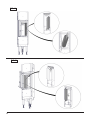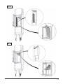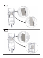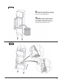
1
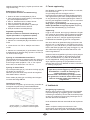
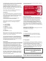
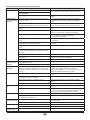
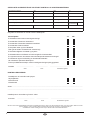
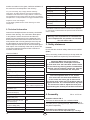
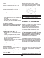
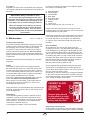
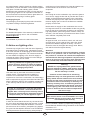
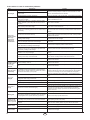
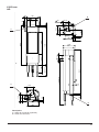
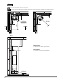
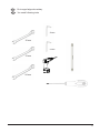
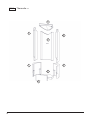
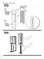
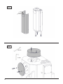
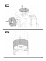
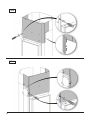
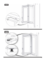
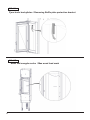
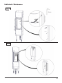
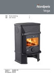
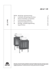
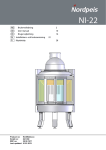
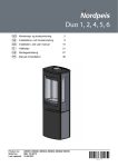
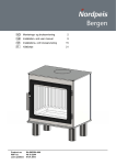
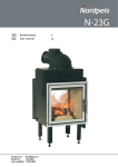
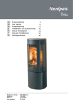
X-20 F
7
NO
8
Brukerveiledning
9
10
User manual
GB
2
11
12
9
A
B
C
D
E
F
G
NAME
7
8
SIGNATURE
DATE
DRAWN
P.Żabiński
2012-07-18
CHK'D
D.Krzyżaniak
2013-11-29
APPV'D
Ł.Kęsy
2013-11-29 WEIGHT: 91.90 (kg)
Product no: IN-0X20F-010
Teknologisk no: 300-ELAB-2025-EN II
Last updated: 130314
NAME:
A2
IN-0X20F-010 X20F - Insert
SCALE:1:5
MATERIAL:
Q0
SHEET 1 OF 1
1
Innhold
1. Før du installerer nytt ildsted
1. Før du installerer nytt ildsted Skorsteinstrekk Tilførsel av luft 2. Teknisk informasjon 3. Sikkerhetsavstander 4. Montering Varmeskjold Montering og justering av ben Bakmontering Røykuttak og tilkobling Øvre varmeskjold Fjerning av selvlukkemekanismen Demontering av dør Kontroll av funksjoner 5. Første opptenning 6. Vedlikehold
Rengjøring og inspisering Aske Thermotte™ Dør og glass 7. Garanti 8. Fyringstips 2
2
2
3
3
3
3
3
4
4
4
4
4
4
4
5
5
5
5
5
6
6
Råd og tips ved problemer med forbrenningen
7
Installasjon av nye ildsteder skal meldes til de lokale
bygningsmyndigheter. Det anbefales å benytte
kompetent personell ved installasjon nytt ildsted.
Huseier står selv ansvarlig for at alle krav til sikkerhet
er ivaretatt på en forskriftsmessig måte og er forpliktet
til å få installasjonen inspisert og sikkerheten bekreftet
av en kvalifisert kontrollør. Kvalifisert kontrollør
kan være feier, murmester, varmeforhandler eller
andre med tilstrekkelig kompetanse. Det er også en
fordel å dokumentere denne kontrollen skriftlig, bruk
gjerne vedlagte kontrollskjema. Lokalt feievesen må
informeres dersom installasjonen medfører endret
feiebehov.
Skorsteinstrekk
Sammenlignet med eldre ildsteder, stiller dagens
rentbrennende ildsteder betydelig større krav til
skorsteinen. Selv det beste ildsted vil fungere
dårlig hvis skorsteinen ikke er riktig dimensjonert
og i god stand. Oppdriften styres hovedsaklig av
røykgasstemperatur, utetemperatur, lufttilførsel og
skorsteinens høyde og innvendige diameter. Anbefalt
skorsteinshøyde er minst 4 meter over røykinnføringen
og en diameter på 150-200mm. Skorsteinens diameter
skal aldri være mindre enn røykinnføringen/røykrøret.
Ved nominell effekt skal det være et undertrykk
i henhold til teknisk tabell.
Trekken øker når:
• skorsteinen blir varmere enn utelufta
• den aktive lengden på skorsteinen over ildstedet
økes
• det er god lufttilførsel til forbrenningen
Er skorsteinen overdimensjonert i forhold til ildstedet,
kan det bli vanskelig å oppnå god trekk, fordi
skorsteinen ikke blir godt nok oppvarmet. I slike
tilfeller kan det lønne seg å ta kontakt med kynding
personell for vurdering av eventuelle tiltak. For kraftig
trekk kan avhjelpes med en trekkbegrenser. Ildstedet
er typetestet og må kobles til skorsteiner som er
dimensjonert for røykgasstemperatur som anvist i
teknisk tabell. Ved behov, ta kontakt med en feier på
forhånd.
Tilførsel av luft (=mm AIR)
Friskluftsett får å tilknytte ildstedet til luft utenfra fås
kjøpt som tilbehør, og vil sikre at tilførsel av luft til
ildstedet blir mindre påvirket av ventilasjonsanlegg,
kjøkkenvifter og andre forhold som kan medføre
undertrykk i rommet. I alle nybygg anbefaler vi på
det sterkeste at det prosjekteres og klargjøres for
direkte tilførsel av luft utenfra. Også i eldre hus kan
bruk av friskluftsett anbefales. Utilstrekkelig tilførsel
av luft utenfra kan medføre undertrykk i rommet der
ildstedet står - og dermed dårlig forbrenning, dårligere
utnyttelse av veden og nedsoting av skorsteinen.
2
NO
For egen sikkerhet, følg monteringsanvisningen.
Alle sikkerhetsavstander er minimumsavstander.
Installasjon av ildsteder må i tillegg være i henhold
til det enkelte lands lover og regler. Nordpeis AS står
ikke ansvarlig for feilmontering av ildstedet.
Røykgasstemperatur (°C)
275 °C
Trekk (Pa)
12 Pa
Brensel
Ved
Vedlengde (cm)
30
Vi tar forbehold om trykkfeil og endringer.
Ileggsmengde (kg)
1,32
Ileggsintervall (min)
45
Driftsform
Intermitterende*
For sist oppdaterte versjon og mer utfyllende
informasjon om brannmurer, pipetilkobling etc., se
våre nettsider www.nordpeis.no
*Med intermitterende forbrenning menes her vanlig bruk av et ildsted.
Dvs at det legges i et nytt ilegg straks brenslet har brent ned til glør.
2. Teknisk informasjon
Ildsteder fra Nordpeis har sekundærforbrenning og
er rentbrennende. Ved sekundærforbrenning skjer
forbrenningen i to trinn: Først brenner veden, deretter
antennes røykgassene av forvarmet luft. Dette gjør at
nye ildsteder har minimalt med utslipp av sotpartikler
og uforbrente gasser (for eksempel CO) og er bedre
for miljøet. Ved går under betegnelse fornybar
ressurs/biobrensel. Rentbrennende ildsteder trenger
lite ved for å oppnå god varmeeffekt. Fyr utelukkende
med ren og tørr ved med fuktinnhold mellom 16% til
20%.
Innsats
X-20F
Materiale
Stål
Overflatebehandling
Varmebestandig lakk
Vekt
92
Trekksystem
Fyringsventil
Forbrenningssystem
Ren forbrenning
Luftbehov (m³/h)
30
Anvendelig effektområde
(rentbrennende) (kW)
3-4 kW
Oppvarmingsareal (m2)
45-60
Maks vedlengde (cm)
40
Røykuttak
Topp
Røykstuss (Ø mm)
Ytre Ø150
Røykgasstemperatur ved
røykstuss (°C)
330 °C
Anbefalt trekk ved
røykstuss (Pa)
>13
Røykavgass tetthet [g/s]
6,0
Data ihht til EN 13 229:2001 / A2:2004
Krav til innluftskanaler
under innsats (cm2)
300 cm²
Krav til utluftskanaler over 350 cm²
innsats (cm2)
Minimumsavstand fra
utluftskanal til tak (mm)
400
Nominell effekt (kW)
4 kW
Virkningsgrad (%)
76 %
CO @ 13% O2 (%):
0,1 %
Advarsel: Opprettholdes IKKE kravet til ventiler,
vil effekten av varmesirkulasjonen bli vesentlig
redusert og overoppheting kan oppstå.
I verste fall kan dette resultere i brann.
3. Sikkerhetsavstander
Brannmur
Sørg for at angitte minimumsavstander overholdes
(FIG 1).
Ved toppmontering til stålpipe henviser vi til respektive
fabrikats monteringsanvisning. Overhold de
sikkerhetsavstandene montering av stålpipen krever.
VIKTIG! Ved plassering av innsatsen på gulv
av brennbart materiale må HELE gulvet
innvendig i omrammingen dekkes av en
stålplate med minimum 0,7 mm tykkelse.
Gulvbelegg som teppe, nålfilt og
lignene under stålplaten må fjernes.
Da innsatsen ekspanderer under fyring må omrammingen ALDRI hvile på innsatsen, men ha
en avstand på ca 3 mm. Innsatsen må heller ikke
hvile på ileggsplaten eller mot sidene.
Det anbefales å tørrstable peisomrammingen
for å justere innsatsen før du tar hull i pipen til
røykrøret.
4. Montering
Varmeskjold FIG 3
Innsatsen er levert med fire varmeskjold. Se figur 3.
Skjold A og D er allerede montert på innsatsen ved
levering, B og C er pakket separat og må monteres.
Montering og justering av ben FIG 4
Innsatsen er levert med justerbare ben. Disse monteres
på innsatsen med medfølgende skiver og bolter (13 mm
fastnøkkel).
Juster bena til ønsket høyde før innsatsen løftes opp i
NO
3
stående posistjon (ikke tipp!). Høyden på varierer etter
valgt omramming.
Bakmontering FIG 5, 6, 7
For å tilpasse innsatsen for bakmontering;
1. Hekt av de bakre varmeskjoldet (A) FIG 5.
2. Fjern utsparingen for bakmontering i varmeskjoldet
(A), bruk beskyttelseshansker.
3. Skru av baklokket med to umbraco skruer.
4. Skru av røykstussen the flue collar.
5. Fest røykstussen på bakuttaket, og lokket på
topputtaket med de samme skruene.
6. Hekt på det bakre varmeskjoldet (A).
Røykuttak og tilkobling
NB! Våre innsatser er utviklet for tilkobling av
røykrør på utsiden* av røykstussen (Ø150).
Montering av øvre varmeskjold FIG 8, 9, 10
1. Plasser øvre varmeskjold (B) på innsatsen som vist i
FIG 8
2. Løsne skruen vist i FIG 9 - detalj A med cirka to
runder.
3. Plasser øvre varmeskjold (C) på innsatsen. Pass på
at sidehektene blir plassert riktig i sporene. Se FIG 9 &
10. Stram til skruen igjen.
Fjerning av selvlukkemekanisme FIG 11
Selvlukkemekanismen er plassert under den nedre hengslen på døren. For å deaktivere denne, hekt forsiktig
av den lange enden på fjæren - FIG 11. For å fjerne
denne helt, ta av døren som vist i FIG 12.
5. Første opptenning
Når ildstedet er installert og alle forskrifter er overholdt,
kan det tennes opp.
Unngå kraftige støt når det legges ved inn i
brennkammeret da dette kan skade isolasjonsplatene.
Vær oppmerksom på at fukt i isolasjonsplatene kan gi
en treg forbrenning de første opptenningene. Dette vil
løse seg når fuktigheten fordamper. Fyr evt. med døren
på gløtt de 2-3 første gangene.
Sørg også for god utluftning ved første fyring, da
lakken på ildstedet vil avgi røyk og lukt. Røyken og
lukten er ikke helseskadelig og vil forsvinne.
Opptenning
Legg inn tørr småved, tenn opp og la flammene få godt
tak i veden før døren lukkes. Åpne opptenningsventilen
når du lukker døren (FIG B). Når flammene er stabile
og pipen er blitt varm, stenges opptenningsventilen. I
motsatt fall kan ildstedet og pipen bli overopphetet.
Når det er dannet et glødende kullag og flammene har
dødd ut, kan ny ved legges inn. Dra glørne frem når du
legger inn ny ved, slik at den nye veden antennes forfra.
Døren skal settes på gløtt hver gang det legges i ny ved
slik at flammene får godt tak. Bålet skal brenne med
friske livlige flammer.
Svært lav forbrenningseffekt og forsøk på fyring døgnet
rundt er uheldig da dette gir økt forurensning og økt
fare for skorsteinsbrann. Fyr aldri slik at ildsted eller
rør blir rødglødende. Steng fyringsventilen hvis dette
skjer. Optimal regulering av fyringsventilen krever litt
erfaring. Når du har fyrt i ildstedet en stund, vil du finne
en naturlig fyringsrytme.
Fjerning av døren FIG 12
Fjern transportsikringen (A). Løft døren forsiktig opp (B)
og dra den ut i bunnen (C).
NB! Pass på å løfte døren høyt nok slik at hengslene
ikke skader lakken i rammen.
NB ! Husk alltid å åpne ventiler (og gjerne
også døren) når det legges ny ved i et varmt
brennkammer. La veden få ordentlig fyr før
ventilinnstillingen reduseres.
Ved lav trekk i skorsteinen og stengte ventiler
kan gassene fra veden bli antent med et smell
som kan forårsake skader på produktet og
omgivelsene.
Døren settes på plass igjen ved å følge anvisningen i
omvendt rekkefølge FIG 12.
Operational control
Når innsatsen er oppstilt, og før innmuring, kontroller at
funksjoner fungerer lett og virker tilfredsstillende.
X-20F innsatsen er utstyrt med kun en fyringsventil.
-
+
6. Vedlikehold
Rengjøring og inspisering
Minst en gang i løpet av fyringssesongen bør ildstedet
inspiseres grundig og rengjøres (gjerne i forbindelse
med feiing av skorstein). Se til at alle sammenføyninger
er tette, og at pakninger ligger riktig. Pakninger som er
slitt eller deformert bør skiftes ut.
Husk at ildstedet alltid må være kaldt før det inspiseres.
Venstre posisjon (-) = minimum forbrenningsluft
Høyre posisjon (+) = maksimum forbrenningsluft
4
Aske
Asken må fjernes med jevne mellomrom. Vær
oppmerksom på at asken kan inneholde glør selv flere
døgn etter at ilden har opphørt. Det anbefales imidlertid
NO
å la det ligge igjen et lag aske i bunnen, da dette bidrar
til å isolere brennkammeret. Bruk en beholder av ikke
brennbart materiale når du fjerner asken.
Innsatsen er levert med utstyr for å fjerne aske. For
detaljerte tegninger, se FIG 22 & 23. Når det kun er
glør igjen i brennkammeret, åpne fyringsventilen helt for
å brene de siste kullbitene til aske.
er tett og fungerer optimalt. Disse fås kjøpt i sett med
keramisk lim inkludert.
PEISGLASS KAN
IKKE GJENVINNES
Vær varsom med Thermotteplatene ved fjerning av
aske, spesielt ved bruk av askespade.
Peisglass skal kastes i
restavfallet sammen med
keramikk og porselen
Thermotte™
De varmeisolerende platene i brennkammeret (FIG 3)
bidrar til å gi høy forbrenningstemperatur, som fører til
renere forbrenning av veden og høyere virkningsgrad.
Eventuelle sprekker i platene forringer ikke
isolasjonsevnen.
Skulle det være behov for å erstatte eller bytte
ut enkelte plater, kontakt din forhandler.
Gjenvinning av glass
Ildfast glass kan ikke gjenvinnes. Alt av gammelt
peisglass, brekkasje eller annet ubrukelig ildfast glass,
må kastes i restavfallet. Ildfast glass har høyrere
smeltetemperatur, og kan derfor ikke gjenvinnes
sammen med brukt emballasjeglass. Blandes dette
med brukt emballasjeglass, ødelegges råvaren og
gjenvinning av brukt emballasjeglass kan i verste fall
stoppe. Når du sørger for at ildfast glass ikke havner i
returpunktene, er det en hjelp som er et viktig bidrag for
miljøet.
Dersom det er nødvendig å ta ut thermotteplatene,
gjøres dette omvendt av rekkefølgen beskrevet
nedenfor.
A. Høyre sideplate
B. Venstre sideplate
C. Røykvenderplate
D. Bakplate
E. Nedre høyre sideplate
F. Nedre venstre sideplate
G. Bunn
H. Nedre front
Se også FIG 14 - FIG 19
Gjenvinning av emballasje
Emballasjen som følger produktet skal gjenvinnes etter
det gjeldene lands forskrifter.
7. Garanti
Merk: Ved bruk av for lang ved vil det medføre ekstra
belastning som kan knekke platene, dersom veden blir
liggende i spenn mellom sideplatene.
For utførlig beskrivelse av garantibestemmelser,
se vedlagte garantikort eller besøk våre nettsider
www.nordpeis.no
Vær også oppmerksom på at Thermotteplatene kan
avgi farget støv ved berøring. Unngå å ta på lakkerte
flater med støv på fingrene. Kommer det støv på noen
av ildstedets synlige overflater er hansken som følger
med godt egnet til å børste av med.
CE merkingen er plassert på siden av innsatsen.
8. Fyringstips
Dør og glass
Dersom glassruten er sotete, kan det være nødvendig å
pusse/rengjøre glasset. Bruk glassrens som er beregnet
for dette (NB! Vær forsikting, glassrens kan skade
lakken på dørrammen og pekninger). Brukes andre
rengjøringsmidler kan det skade glasset. Et godt tips til
rengjøring er å bruke en fuktig klut eller kjøkkenpapir
med litt aske fra brennkammeret. Gni asken rundt på
glasset og tørk av med et rent og fuktig kjøkkenpapir.
NB! Rengjøring må kun gjøres når glasset er kaldt.
Kontroller regelmessig at overgangen mellom glasset
og døren er helt tett. Stram eventuelt til skruene som
holder glasset på plass – men ikke for hardt, da dette
kan føre til at glasset sprekker.
Med jevne mellomrom kan det være nødvendig å skifte
tetningslistene på døren for å sikre at ildstedet fortsatt
Den beste måten å tenne opp et ildsted er ved bruk av
opptenningsbriketter og kløyvet, tørr småved. Aviser gir
mye aske og trykksverten er ikke bra for miljøet.
Reklamer, magasiner, melkekartonger og lignende er
ikke egnet for opptenning i peis. Det er viktig med god
lufttilførsel ved opptenning. Når pipen blir varm øker
trekken og døren kan lukkes.
Advarsel: Bruk ALDRI opptenningsvæske
som bensin, parafin, rødsprit eller lignende
til opptenning. Du kan skade både deg selv
og produktet
Bruk alltid ren og tørr ved med et maksimalt fuktinnhold
på 20%. Veden bør minimum tørkes et halvt år etter
hugging. Fuktig ved krever mye luft til forbrenningen
NO
5
fordi det må brukes ekstra energi/varme til å tørke ut
det fuktige treet. Dette gir mindre varmeavgivelse til
omgivelsene samtidig som det fører til sotdannelse på
glasset og i pipen, med fare for beksot og pipebrann.
Advarsel:
Bruk ALDRI impregnert tre, malt tre,
plastlaminat, kryssfiner, sponplater, avfall,
melkekartonger, trykksaker eller lignende.
Ved bruk av disse materialene bortfaller
garantien, da de kan avgi dioksingasser som
skader ildstedet når de forbrennes.
Felles for disse materialene er at de under
forbrenning kan danne saltsyre og tungmetaller
som er skadelige for miljøet, deg og ildstedet.
Saltsyren kan også angripe stålet i pipen eller
murverket i en murt pipe. Unngå også å fyre med
bark, sagspon eller annet ekstremt fint kløyvet
ved unntatt ved opptenning. Denne form for
brensel gir lett overtenning som kan resultere i
for høy effekt.
NB! Dersom pipebrann skulle oppstå, lukk
døren, steng forbrenningsluften og ring
brannvesenet. Etter en pipebrann skal pipen og
ildstedet alltid inspiseres av autorisert personell
før disse tas i bruk igjen.
Lagring av ved
For å forsikre seg om at veden er tørr, bør treet
felles om vinteren og lagres om sommeren under tak
på et sted med god utlufting. Vedstabelen må aldri
dekkes av en presenning som ligger mot jorden, da
presenningen vil fungere som et tett lokk som vil
forhindre veden i å tørke. Oppbevar alltid en mindre
mengde ved innendørs i noen dager før bruk, slik at
fukten i overflaten på veden kan fordampe.
Fyring
Det er best å fyre jevnlig med en liten mengde ved. Hvis
det legges for mange kubber på et glødelag vil det være
for lite tilsig av luft til at temperaturen i brennkammeret
blir høy nok. Ved for lav temperatur i brennkammeret
forsvinner gass uforbrent ut igjennom pipen.
Advarsel: Pass på at produktet ikke blir
overopphetet – det kan føre til uopprettelig skade
på peisen. Slike skader dekkes ikke av garantien.
Kilde: “Håndbok, effektiv og miljøvennlig vedfyring” av Edvard
Karlsvik
SINTEF Energiforskning as og Heikki Oravainen, VTT.
http://www.eufirewood.info
For lite luft kan også medføre at glasset sotes. Tilfør
derfor luft til bålet like etter at brenselet er lagt på, slik at
det er flammer i brennkammeret og gassene
forbrennes. Åpne opptennings-/fyringsventilen eller ha
døren litt på gløtt til flammene får godt tak.
Merk at lufttilførsel til forbrenningen også kan bli for
stor og gi en ukontrollerbar flamme som svært raskt vil
varme opp hele ildstedet til en ekstremt høy temperatur
(gjelder fyring med lukket, eller nesten lukket dør). Fyll
derfor aldri brennkammeret helt opp med ved.
Valg av brensel
Alle typer tre, som bjørk, bøk, eik, alm, ask og frukttre
kan brukes som brensel i innsatsen. Tresorter har
forskjellige hardhetsgrader - jo høyere hardhetsgrad
veden har, desto høyere er energiverdien. Bøk, eik og
bjørk har den høyeste hardhetsgraden.
NB! Vi anbefaler ikke bruk av fyringsbriketter/
kompaktved i våre brennkamre, da disse
produktene kan utvikle vesentlig høyere temperatur
enn brennkammeret tåler.
Fyringsbriketter/kompaktved anvendes på eget
ansvarog kan føre til at garantien bortfaller.
6
NO
Råd og tips ved problemer med forbrenningen
Feil
Manglende trekk
Forklaring
Utbedring
Pipen er tilstoppet.
Røykrøret er tilsotet, eller det er sotansamling på
røykvenderplaten.
Røykvenderplaten kan sitte galt.
Kontakt feier/se fyrings DVD for ytterligere informasjon
eller rens røykrør, røykvenderplate og brennkammer.
Kontroller monteringen av røykvenderplaten - se bruksanvisning.
Ildstedet ryker
Undertrykk i rommet der ildstedet står. For lite trekk,
under opptenning huset er for ”tett”.
og drift
Fyr opp med et åpent vindu i rommet. Hjelper dette,
må det installeres flere/større ventiler til uteluft/friskluft i
rommet.
Undertrykk i rommet - kjøkkenvifte og/eller sentralt
ventilasjonsanlegg trekker for mye luft ut av rommet.
Slå av/reguler kjøkkenvifte og/eller annen ventilasjon.
Hjelper dette må det settes inn flere ventiler i rommet
Røykrør fra to ildsteder er tilsluttet skorsten i samme
høyde.
Monter om slik at høydeforskjell mellom røykrør er minst
30 cm
Røykrøret heller nedover.
Røykrør må flyttes slik at det er stigende fra ildsted til
pipe, min. 10 grader. Evt. montering av røyksuger.
Røykrøret stikker for langt inn i pipeløpet.
Monter om røykrøret slik at det ikke stikker inn i pipeløpet,
men avsluttes 5 mm før pipens innervegg.
Evt. montering av røyksuger.
Feieluke i kjeller eller loft står åpen og skaper falsk
trekk.
Feieluker må alltid være lukket. Utette eller defekte feieluker må skiftes.
Spjeld/trekkventiler eller dører på ildsteder som ikke er
i bruk står åpne og skaper falsk trekk.
Steng spjeld, dører og trekkventiler på ildsteder som ikke
er i bruk.
Åpent hull i pipen etter fjernet ildsted skaper falsk
trekk.
Hull må mures igjen.
Defekt murverk i pipen, f.eks. utetthet rundt rørgjennomføring og/eller ødelagt vegg i røykløp som skaper
falsk trekk.
Tett igjen og puss alle sprekker og utettheter.
For stort tverrsnitt i pipen gir liten eller ingen trekk.
Pipen må rehabiliteres, evt. montering av røyksuger*.
For lite tverrsnitt, klarer ikke å transportere all
røykgass ut
Bytt til et mindre ildsted eller bygg ny pipe med større
tverrsnitt. Evt. montering av røyksuger.
For lav pipe som gir dårlig trekk.
Øk pipehøyden og/eller monter pipehatt/røyksuger*.
Ildstedet ryker
inne når det er
vind ute
Pipen ligger for lavt i forhold til omkringliggende terreng, bygninger, trær e.l.
Øk pipehøyden og/eller monter pipehatt/røyksuger*.
Turbulens rundt pipen pga. for flatt tak.
Øk pipehøyden og/eller monter pipehatt/røyksuger*.
Ildstedet varmer
for dårlig
Ildstedet får for mye surstoff til forbrenningen pga
lekkasje i underkant av ildstedet el. for stor pipetrekk.
Vanskelig å regulere forbrenningen og veden brenner
fort opp.
Eventuelle lekkasjer må tettes. Trekken kan reduseres
ved hjelp av en trekkbegrenser eller evt. spjeld.
Obs! En lekkasje på bare 5 cm² er nok til at 30 % av den
produserte varmluften forsvinner ”rett i pipa”.
For mye trekk
Røykvenderplaten kan sitte galt.
Kontroller monteringen av røykvenderplaten - se bruksanvisning.
Hvis du bruker ovnstørket tre, krever dette mindre
lufttilførsel enn ved normal brensel.
Skru ned lufttilførselen.
Tetingslistene ved døren er nedslitte og flate.
Skift ut tetningslistene hvis de er nedslitte, kontakt forhandler.
Pipen er for stor.
Kontakt feier/ovnsforhandler for ytterligere veiledning.
Treet er for vått.
Bruk kun tørr fyringsved med en maksimal fuktighet på
20 %.
Luftventilen er lukket for mye.
Åpne ventilen så det tilføres mer luft til forbrenningen.
Ved ilegg av ny ved skal ventiler alltid ha full åpning eller
det fyres med døren på gløtt til flammene får tak.
Dårlig forbrenning (for lav temperatur i ovnen)
Følg instruksjonene for riktig fyring som beskrevet.
Feil fyring (fyring med avfallstre, malt tre, impregnert
tre, plastlaminat, kryssfiner o.l.)
Fyr utelukkende med ren og tørr ved.
Det oppstår en trykkutjevning i brennkammeret.
Lukk opp ventiler ca 1 min. før døren åpnes - unngå å
åpne døren raskt.
Døren åpnes når det er ild i brennkammeret.
Åpne døren forsiktig og/eller kun ved gløding.
Forbrenningstemperaturen er for lav.
Øk lufttilførselen.
Treet er for fuktig og inneholder vanndamp.
Fyr utelukkende med ren og tørr ved.
Ufullstendig forbrenning.
Øk lufttilførselen.
Glassruten sotes
til
Hvitt glass
Røyk ut i stuen
når døren åpnes
Hvit røyk
Svart eller
gråsvart røyk
NO
7
SJEKKLISTE OG BEKREFTELSE PÅ UTFØRT KONTROLL AV ILDSTEDSMONTERING
Eiendommens adresse
Gnr
Bnr
Tlf
Eiers navn
Adresse
Postnummer
Sted
Montørens navn
Adresse
Postnummer
Sted
Ildstedstype og fabrikk
Effekt i kW
Brenseltype
Skorstenstype (Eks. tegl, type elemtskorsten)
Installasjonen er kontrollert av
Adresse
Dimensjon i cm²
Ant. ildsteder
på skorstenen
Postnummer
Sted
Kvalifikasjon
Følgende ble kontrollert av montør under installasjonen:
Kontrollpunkt
Ja
Nei
Er ildstedet montert etter monteringsanvisning?
Er avstanden til brannmur kontrollert?
Er avstanden til brennbart materiale kontrollert?
Er avstanden til tak kontrollert?
Er det plate under og foran ildstedet?
Tåler gulvet vekten av ildsted med omramming?
Er det feiemuligheter for ildsted og røykrør?
Er ildstedet sikret nok tilførsel av forbrenningsluft via lufteventiler?
Er røykrøret montert i skorstenen etter skorstensprodusentens anvisninger?
Er skorstenen egnet for tilkobling av det aktuelle ildstedet?
Har skorstenen passende dimensjon?
Finnes produktdokumentasjon med monteringsanvisningen på byggeplass?
Installert
..................................................
...................................
..........................................................................
Sted
Dato
Montørens signatur
KONTROLLERKLÆRING
Installasjonen er kontrollert ved hjelp av:
Utfylt sjekkliste
Visuell kontroll
Videokamera
Annet: .......................................................................................................................................................................
..................................................................................................................................................................................
Installasjonen er kontrollert og funnet i orden:
Kontrollert
..................................................
...................................
......................................................................
Sted
Dato
Kontrollørens signatur
Det er en stor fordel at bekreftelse på kontroll av installasjonen finnes. Sørg for at denne siden blir utfylt, og ta vare på den. Dette er et verdipapir for boligen. Husk at huseier plikter å melde fra til kommunen ved brann- og feiervesenet om
at ildstedet er montert. Send gjerne en kopi av denne siden til det lokale feiervesen.
8
NO
Index
1. Prior to assembling the insert
1. Prior to assembling the insert Chimney Draft
Air Supply 9
9
9
2. Technical Information 10
3. Safety distances
10
4. Assembly Radiation shields
Assembling and adjusting the legs
Rear flue gas connection
Flue collar and connection Assembling upper covers
Removing the self closing mechanism
Removing the door Operational control 5. Lighting the fire for the first time 10
10
10
11
11
11
11
11
11
6. Maintenance
Cleaning and inspection
Ashes Thermotte™
Door and glass 12
12
12
12
12
7. Warranty
8. Advice on lighting a fire 13
13
Some advice in case of combustion problems
14
11
All our products are tested according to the latest
European requirements and also to the Norwegian
standard NS 3058 and NS 3059, which include particle
tests. However, several European countries have local
regulations for installation of fireplaces, which change
regularly. It is the responsibility of the client that these
regulations are complied with in the country/region
where the fireplace is installed. Nordpeis AS is not
responsible for incorrect installation.
Important to check
(please note that this list is not exhaustive):
• distance from firebox to combustible/flammable
materials
• insulation materials/requirements between
fireplace surround and back wall
• size of floor plates in front of fireplace if required
• flue connection between firebox and chimney
• insulation requirements if flue passes through a
flammable wall
Chimney draft
Compared with older models, the clean burning inserts
of today put significantly higher demands on the
chimney. Even the best insert will not work properly
if the chimney does not have the right dimensions or
is not in good working order. The draught is mainly
controlled by gas temperature, outside temperature, air
supply as well as the height and inner diameter of the
chimney. The diameter of the chimney should never
be less than that of the flue/chimney collar. For draft
requirements at nominal heat output, see technical
table
The draught increases when:
• The chimney becomes warmer than the outside air
• The active length of the chimney over the hearth
increases
• Good air supply to the combustion
It can be difficult to obtain the right draught conditions
in case the chimney is too large relative to the insert,
as the chimney does not heat up well enough. In such
cases you may want to contact professional for
evaluation of possible measures. Draught that is too
strong can be controlled with a damper. If necessary,
contact a chimney sweeper.
Air supply
A set for fresh air supply is available as an accessory.
This will ensure that the air supply to the combustion
chamber is less affected by ventilation systems, kitchen
fans and other factors which can create a down-draught
in the room. In all new constructions, we strongly
recommend the product is designed and prepared
for direct supply of outside air. In older houses also,
the use of fresh air supply set is also recommended.
Insufficient air supply can cause poor draught and
thereby low combustion efficiency and the problems this
GB
9
entails: soot stains on the glass, inefficient utilisation of
the wood and a soot deposits in the chimney.
CO @ 13% O2 (%)
Flue gas temperature (°C) 275
For your own safety, fully comply with the assembly
instructions. All safety distances are minimum distances.
Installation of the insert must comply with the current rules
and regulations of the country where the product is installed.
Nordpeis AS is not responsible for wrongly assembled inserts.
Inserts from Nordpeis all have secondary combustion
and are clean burning. The combustion takes place
in two phases: first the wood burns and then the
gases from the fumes are lit by the heated air. This
ensures that new inserts have minimal emissions of
soot particles and un-burnt gases (such as CO) and
are thus better for the environment. Clean burning
inserts require a small amount of wood to obtain good
heat output. Use exclusively clean and dry wood. We
recommend seasoned hardwood with a maximum
moisture content of 20%.
Technical TABLE
Insert
X-20F
Material
Steel
Surface treatment
Heat resistant varnish
Weight of insert (kg)
92
Draught system
Ignition air vent control
Combustion system
Clean burning
Combustion air consumption
(m³/h)
8-16
Operating range, Clean burn
(kW)
3-4
Heating area (m2)
45-60
Maximum fuel length (cm)
40
Flue outlet
Top and rear
Flue collar (Ø mm)
Outer 150
330
Draft at flue connector
recommended (Pa)
14-25
Data according to EN 13 229
Area of convection air vent
under insert (cm2)
300
Area of convection air vent
over insert (cm2)
350
Minimum distance conv. air
outlet to ceiling (mm)
400
Nominal heat output (kW)
4,0
Efficiency (%)
76
10
>13
Fuel recommended:
Wood logs
Fuel charge (kg)
1,32
Refueling interval
(minutes)
45
Operation*
Intermittent*
* Intermitent combustion refers to normal use of a fireplace,
i.e. new wood is inserted when the previous load has burned
down to ember
Warning: If the requirements for ventilation are
NOT complied with, the product can overheat.
This can cause a fire.
3. Safety distances
Firewall
Ensure that the minimum safety distances are fullfiled
(FIG 1).
When connecting a steel chimney to the top outlet use
the security distances required by the manufacturer.
Important! When placing the insert on
a combustible floor, a steel plate of at least
0.7mm must cover the entire floor surface inside
the surround. Any flooring made of combustible
material, such as linoleum, carpets etc. must be
removed from underneath the steel plate.
The insert expands when in use, and for
this reason the surround must NEVER rest
on the insert, but have a gap of about 3 mm.
The insert must neither rest on the bench plate or
against the sides. It is recommended to dry stack
the surround in order to adjust the insert prior
to perforating the chimney for the flue connection.
*alternate versions exists
due to nationa lrequirements
Flue gas temperature at flue
connector (°C)
Draft (Pa)
Fuel length recommended 30
(cm)
Subject to errors and changes.
For the latest updated version of the manual go to www.
nordpeis.eu
2. Technical information
0,1
4. Assembly
FIG 3 - to FIG 12
Radiation shields FIG 3
The insert is delivered with four radiation shields.
See Figure 3. Covers A and D are already mounted at
the insert prior to opening package, while cover B and C
are packed separately.
Assembling and adjusting the legs FIG 4
The insert is delivered with adjustable legs. The legs
GB
Operational control
When the insert is in upright position, and prior
to mounting the surround, control that all functions are
easy to maneuver and appear satisfactory. The X-20F
insert is equiped only with an Ignition vent control
are mounted on to the insert using the added bolts and
washers.
Fasten the screws on to the insert with a 13 mm
wrench.
Adjust legs to the desired height before returning the
insert to an upright position (do not tilt the insert).
The height varries according to the surround.
-
Rear flue gas connection FIG 5, 6, 7
To utilize the rear connection on the insert, do as
follows:
+
1. Remove the rear radiation shield FIG 5.
2. Remove the cut in the rear radiation shield, use
protective gloves.
3. Remove the plate covering the rear connection (two
allen screws).
4. Remove the flue collar (two allen screws).
5. Move the flue collar to the rear outlet and the cover
plate to the top connection (use the same screws).
6. Put back rear shield on the insert.
Ignition vent control
Left position (-) = minimum ignition air
Right position (+) = maximum ignition air
5. Lighting a fire for the first time
When the insert is assembled and all instructions have
been observed, a fire can be lit.
Take care when inserting logs into the burn chamber, in
order not to damage the Thermotte plates.
The horizontal mark on the back of the combustion
chamber indicates maximum intended woodloading
hight. See drawing FIG 13. Please note that there might
be some humidity in the insulation lates which can result
in a slower burn rate the first few times the insert is
used. This will be resolved once the humidity has
evaporated. If needed leave the door slightly open the
first 2-3 times the insert is used.
It is advisable to ventilate the room well when using
for the first time as the varnish on the product may
release some smoke or smell. Both the smoke and
smell will disappear and are not hazardous.
Flue collar and connection
Attention! Our inserts are prepared for connecting
the smoke pipe on the outside of the flue collar
Ø150.
*Alternative versions of the flue collar exist due to
National requirements. For the flue connection to the
chimney, follow the recomenndations from the chimney
manufacturer.
Assmebling Upper Covers FIG 8, 9, 10
1. Place rear upper cover on the insert as it is shown
on FIG 8.
2. Loosen the screw shown on the FIG 9 - Detail A,
unscrewing it by approximately 720 degree.
3. Take front upper cover - place on the Insert.
Pay attention that small assembling plates, on the
cover side, have to be inserted to the side slots of
rear cover. See FIG 9 & 10.
4. The assembling is completed when cover is fastened
by the screw - FIG 10 - Detail D.
Removing the self closing door mechanism FIG 11
The self closing mechanism is located on the bottom
hinge. To deactivate it, carefully unhook the long end of
the spring. To completely the spring, remove the door as
shown in FIG 12
Removing the door FIG 12
Remove door protection (A). Carefully lift the door up
(B) and pull it out at the bottom (C).
Attention! Be carefull to lift the door high enough so that
the hinge does not scratch the paint on the frame.
The door is installed by following the same steps in
reverse order FIG 12.
Lighting a fire
Insert small, dry pieces of wood, ignite and ensure the
flames have a good grip of the wood before closing the
door. Open the ignition vent control as you close the
door. When the flames are stable and the chimney is
warm, close the ignition vent control. If it is not closed
the insert and chimney may overheat
When there is a glowing layer of ash, new wood logs
can be inserted. Pull the hot ember to the front of the
combustion chamber when inserting new logs so that
the wood is ignited from the front. Keep the door slightly
open each time new logs are inserted so that the flames
get established. The fire should burn with bright and
lively flames.
Using the insert with low combustion effect and firing
around the clock increase pollution as well as the risk
for a fire in the chimney. Never allow the insert or flue to
become glowing red. Turn off the air vent control should
GB
11
this happen.
Regulation of the air vent control takes some experience, but after a little while a natural rhythm for the fire will
be found.
IMPORTANT! Always remember to open
the air vent control (preferably also the door)
before new wood logs are inserted into a hot burn
chamber. Let the flames get a good grip on the
wood before the air control setting is reduced.
When the draught in the chimney is low and
the vent is closed, the gas from the firewood
can be ignited with a bang. This can cause
damage to the product as well as the immediate
environment.
6. Maintenance
FIG 14 - to FIG 23
Cleaning and inspection
The insert should be inspected thoroughly and clened
at least once per season (possibly in combination with
the sweeping of the chimney and chimney pipes).
To see how to get access to the chimney in order to
chimney sweep see drawings from FIG 14 to FIG 21.
Ensure that all joints are tight and that the gaskets are
rightly positioned. Exchange any gaskets that are worn
or deformed.
Remember that the insert must always be cold when
inspected.
Ashes
The ashes should be removed at regular intervals.
Be aware that the ashes can contain hot ember even
several days after the fire is finished. Use a container
of non-combustible material to remove the ashes. It is
recommended to leave a layer of ashes in the bottom
as this further insulates the burn chamber.
The insert is delivered with dedicated tools to remove
ashes. For details see drawings FIG 22 & 23.
When the fire is out and there is only ember left turn
the Air ignition control to maximum in order to turn
remaining charcoal into ash.
In case it is necessary to take out the insulation plates,
this is done in followieng order.
A. Right side plate
B. Left side plate
C. Smoke baffle
D. Back plate
E. Right lower side
F. Left lower side
G. Bottom
H. Lower front
See also drawings from FIG 14 to FIG 19.
Please note: Wood logs that are too long can cause
additional strain and crack the plates, due to the tension
created between the side plates.
Please also note that the Thermotte plates may release
coloured dust when touched. Avoid touching any cast
iron parts with dust on your fingers. Any visible dust
on cast iron can be brushed off with the glove that is
included.
Door and Glass
Should there be any soot on the glass it may be
necessary to clean it. Use dedicated glass cleaner, as
other detergents may damage the glass. (NB! Be careful, even dedicated glass cleaner can damage the varnish on the door frame and the gaskets). A good advice
for cleaning the glass is to use a damp cloth or kitchen
roll paper and apply some ash from the burn chamber.
Rub around the ash on the glass and finish off with a
piece of clean and damp kitchen roll paper.
NB! Only clean when the glass is cold.
Check regularly that the transition between the glass
and the door is completely tight. Possibly tighten the
screws that hold the glass in place - but not too hard, as
this can cause the glass to crack.
Periodically, it may be necessary to change the gaskets
on the door to ensure that the burn chamber is air tight
and working optimally. These gaskets can be bought as
a set, usually including ceramic glue.
CERAMIC GLASS
CANNOT BE
RECYCLED
Take care with the Thermotte plates when the ashes are
removed, particularly when using an ash shovel, so as
not to damage them.
Thermotte™
These insulating plates in the burn chamber (FIG 2)
contribute to a high combustion temperature, which
leads to cleaner combustion of the wood and a higher
rate of efficiency. Any fissures in the plates will not
reduce their insulation efficiency.
If new plates are needed, contact your dealer.
Ceramic glass should
be disposed of as residual waste, together with
pottery and porcelain
Recycling of ceramic glass
Ceramic glass cannot be recycled. Old glass, breakage
or otherwise unusable ceramic glass must be discarded
12
GB
as residual waste. Ceramic glass has a higher melting
temperature, and can therefore not be recycled together
with glass. If mixed with ordinary glass, it would
damage the raw material and could, in worst case end
the recycling of glass. It is an important contribution to
the environment to ensure that ceramic glass does not
end up with the recycling of ordinary glass.
Packaging Recycle
The packaging accompanying the product should be
recycled according to national regulations.
Usage
Not enough air to the combustion may cause the glass to
soot. Hence, supply the fire with air just after the wood is
added, so that the flames and gases in the combustion
chamber are properly burnt. Open the air vent and have
the door slightly ajar in order for the flames to establish
properly on the wood.
Note that the air supply for the combustion also can be
too large and cause an uncontrollable fire that very quickly
heats up the whole combustion chamber to an extremely
high temperature (when using with a closed or nearly closed door). For this reason you should never fill the combustion chamber completely with wood.
7. Warranty
For detailed description of the warranty conditions see
the enclosed warranty card or visit our website
www.nordpeis.eu
The CE mark is placed on the side of the insert.
8. Advice on lighting a fire
The best way to light a fire is with the use of lightening
briquettes and dry kindling wood. Newspapers cause
a lot of ash and the ink is damaging for the environment.
Advertising flyers, magazines, milk cartons and similar
are not suitable for lighting a fire. Good air supply is
important at ignition. When the flue is hot the draught
increases and door can be closed
Warning: NEVER use a lighting fuel such as
petrol, karosine, alcohol or similar for lighting
a fire. This could cause injury to you as well as
damaging the product.
small amount of wood indoors for a few days before use
so that moisture in the surface of the wood can
evaporate.
Choice of fuel
All types of wood, such as birch, beech, oak, elm, ash
and fruit trees, can be used as fuel in the insert. Wood
species have different degrees of density - the more
dense the wood is, the higher the energy value. Beech,
oak and birch has the highest density.
Attention!
We do not recommend using fuel briquettes/ compact
wood in our products. Use of such fuel may cause
the product to overheat and exceed the temperatures
determined safe. Burning briquettes/ compact wood is
done so at your own risk and only small amounts (max
1/3 of normal load) should be used for each load.
Warning:
NEVER use impregnated wood, painted wood,
plywood, chipboard, rubbish, milk cartons, printed
material or similar. If any of these items are used as
fuel the warranty is invalid.
Use clean and dry wood with a maximum moisture
content of 20%. The wood should be dried for a
minimum of 6 months after it is cut. Humid wood
requires a lot of air for the combustion, as extra energy/
heat is required for drying the humid wood and the heat
effect is therefore minimal. This in addition creates soot
in the chimney with the risk of creosote and chimney
fire.
Common to these materials is that during
combustion they can form hydrochloric acid and
heavy metals that are harmful to the environment,
yourself and the insert. Hydrochloric acid can also
corrode the steel in the chimney or masonry in a
masonry chimney. Also, avoid burning with bark,
sawdust or other extremely fine wood, apart from
when lighting a fire. This form of fuel can easily
cause a flashover that can lead to temperatures
that are too high.
In case of a chimney fire, close the door and air
supplies on the stove / insert and call the Fire
Brigade. After a chimney fire the chimney must in
all cases be inspected by an authorized chimney
sweeper before you use the appliance again.
Storing of wood
In order to ensure that the wood is dry, the tree should
be cut in winter and stored during the summer, covered
and in a location with adequate ventilation. The wood
pile must never be covered by a tarpaulin lying against
the ground as the tarpaulin will then act as a sealed lid
that will prevent the wood from drying. Always keep a
Warning:
Make sure the insert is not overheated it can cause
irreparable damage to the product. Such damage is
not covered by the warranty.
Source “Håndbok, effektiv og miljøvennlig vedfyring” by
Edvard Karlsvik SINTEF Energy Research AS and Heikki
Oravainen, VTT.
http//www.eufirewood.info
GB
13
Some advice in case of combustion problems
Error
Explanation
Solution
The chimney is blocked.
No draught
The smoke baffle is wrongly positioned.
Verify the assembly of the smoke baffle - see assembly instructions.
Downdraught in the room caused by no draught, that the
house is too “air tight”.
Light the fire with an open window. If this helps, more/bigger vents
must be installed in the room.
Downdraught in the room – caused by extractor and/or
central ventilation system that pulls too much air out of
the room.
Turn off/regulate extractor and/or other ventilation. If this helps, more
vents must be installed.
The flues from two fireplaces/stoves are connected to the
same chimney at the same height.
One flue must be repositioned. The height difference of the two flue
pipes must be of at least 30 cm.
The flue is in a declining position from the smoke dome to
the chimney.
The flue must be moved so that there is an inclination of at least
10º from smoke dome to chimney. Possibly install a smoke suction
device*.
The flue is too far into the chimney.
The flue must be reconnected so that it does not enter into the chimney but ends 5 mm before the chimney inner wall. Possibly install a
smoke suction device*.
Soot hatch in the basement or attic that is open and thus
creating a false draught.
Soot hatches must always be closed. Hatches that are not tight or
are defected must be changed.
Damper/top draught vents or doors on fireplaces that are
not in use are open and create a false draught.
Close damper, doors and top draught vents on fireplaces that are
not in use.
An open hole in the chimney after that a fireplace has
been removed, thus creating a false draught.
Holes must be completely sealed off with masonry.
Defect masonry in the chimney, e.g. it is not airtight
around the flue pipe entry and/or broken partition inside
the chimney creating a false draught.
Seal and plaster all cracks and sites that are not tight.
The cross-section in the chimney is too large which
results in no or very low draught.
The chimney must be refitted, possibly install a smoke suction
device*.
The cross-section in the chimney is too small and the
chimney cannot carry out all the smoke.
Change to a smaller fireplace or build new chimney with a larger
cross section. Possibly install a smoke suction device*.
The chimney is too low and hence a poor draught.
Increase the height of the chimney and/or install a chimney cap/
smoke suction device*.
The chimney is too low in relationship to the surrounding
terrain, buildings, trees etc.
Increase the height of the chimney and/or install a chimney cap/
smoke suction device*.
Turbulence around the chimney due to the roof being too
flat.
Increase the height of the chimney and/or install a chimney cap/
smoke suction device*.
The fireplace combustion receives too much oxygen due
to a leakage under the lower border of the insert or too
strong chimney draught. Difficult to regulate the combustion and the wood burn up too quickly.
Any possible leakage must be sealed off. A draught regulator or
possibly a damper can reduce the chimney draught. NB! A leakage
of only 5 cm2 is enough for 30% of the heated air to disappear.
The smoke buffer is wrongly positioned.
Verify the positioning of the smoke buffer – see assembly instructions.
In case of using oven-dried wood, this requires less air
supply than when using normal wood.
Turn down the air supply.
The gaskets around the door are worn and totally flat.
Replace the gaskets, contact your dealer.
The chimney is too large.
Contact chimneysweeper or other professional for more details.
The wood is too wet.
Only use dry wood with a humidity of maximum 20%.
The air vent control is closed too tightly.
Open the air vent control to add air to the combustion. When new
wood logs are inserted all vent controls should be completely
opened or the door slightly opened until the flames have a good
take on the wood.
Bad combustion (the temperature is too low).
Follow the guidelines in this user guide for correct combustion.
White glass
Using wrong material for combustion (such as: painted
or impregnated wood, plastic laminate, plywood etc).
Ensure to use only dry and clean wood.
Smoke is released when the
door is opened
A levelling out of pressure occurs in the burn chamber.
Open the air vent control for about 1 min before opening the door –
avoid opening the door too quickly.
The door is opened when there is a fire in the burn
chamber.
Open the door carefully and/or only when there is hot ember.
The combustion temperature is too low.
Increase the air supply.
The wood is humid and contains water damp.
Ensure to use only dry and clean wood.
Insufficient combustion.
Increase the air supply.
The insert
release smoke
when lighting the fire
and during
combustion
The fireplace
releases smoke
inside when
it is windy
outside.
The fireplace
does not heat
sufficiently.
Too much
draught
The glass is
sooty
White smoke
Black or grey/
black smoke
14
Contact a chimney sweeper / dealer for more information or clean
the flue, smoke baffle and burn chamber.
The flue is sooty or there is accumulated soot on the
smoke baffle.
GB
A
Description:
DRAWN
P.Żabiński
2012-07-18
A - CHK'D
UpperD.Krzyżaniak
air connector (optional)
WEIGHT: 93.98 (kg)
Ł.Kęsy
B - APPV'D
Lower air
connector
NAME
D
SIGNATURE
DATE
MATERIAL:
1203
52
2
78
164
118
236
A
25
1188-1348
1057
580
48
150
325
34
1
215-345
185
1082
A
28
95
179
This document is Nordpeis (Northstar Sp. z o.o.) exclusive intellectual property. It must be treated as strictly confidential
and must not be copied or communicated to any third person without Nordpeis (Northstar Sp. z o.o.) written permission
X-20F=mm
AIR
3
4
331
150
B
131,5
B
187
37,5
72,5
318
290
C
164
37,5
E
B
284
F
IN-0X20F-010 X20F - Insert
NAME:
SCALE:1:10
A4
Q0
SHEET 2 OF 2
15
This document is Nordpeis (Northstar Sp. z o.o.)exclusive intellectual property. It must be treated as strictly confidential
and must not be copied or communicated to any third person without Nordpeis (Northstar Sp. z o.o.) written permission
D ≥ 400 mm
1
1
3
2
2
4
3
3
70
5
4
4
70
≥350cm2
5
F
5
7
A
A
6
6
7
7
8
8
DRAWN
P.Żabiński
2012-07-18
CHK'D
D.Krzyżaniak
2013-11-29
APPV'D
Ł.Kęsy
F
NAME
8
SIGNATURE
9
DRAWN
P.Żabiński
CHK'D
D.Krzyżaniak
APPV'D
Ł.Kęsy
NAME
SIGNATURE
3
6
2
2
1
1
n
4
E
5
30
30
6
D
7
C
8
B
=Brennbart materiale/Brændbart materiale/ Brännbart material/ Tulenarka materiaali/ Combustible material
F
F
G
G
H
2013-11-29 WEIGHT: 91.90 (kg)
DATE
NAME:
IN-0X20F-010 X20F - Insert
2013-11-29 WEIGHT: 91.90 (kg)
2012-07-18
DATE
MATERIAL:
R - radius to furniture (combustible)
Description:
10
MATERIAL:
Q0
11
SHEET 1 OF 1
SCALE:1:5
A2
A
A
B
B
C
C
D
D
E
E
≥300cm2
F
G
G
H
16
2013-11-29
NAME:
IN-0X20F-010 X20F - Insert
Q0
SHEET 1 OF 1
SCALE:1:5
A2
R≥700
30
A-A
Beskrivelse:
R - Radius til møbler (brennbar)
12
NA
M
P.Ż
E
ab
ińsk
i
nia
k
rzy
ża
ęsy
E
Ł.K
E
D.K
DR
AW
CH
N
K'D
PV
'D
=Brannmur/ Brandmur/ Palomuuri/ Firewall
AP
20
12
RE
DA
TE
-0
20
7-1
13
8
-1
20
1-2
13
9
-1
1-2
9
W
EIG
HT:
91
.90
SIG
NA
TU
A
(k
g)
1
FIG 1
l
a o
nti si
e is
d rm
nfi e
o p
c n
tly tte
ric ri
st w
s .)
a .o
d o
te . z
a p
e S
tr r
e a
b hst
rt
ust o
m (N G
It is
y. e
rt p
e rd
p o
ro t N
lp u
a o
tu ith
c w
lle n
te o
in ers
e p
siv d
lu thir
xc
e y
.) an
.o
o to
.z d
p te
rS a
a nic
hst u
rt m
o m
(N o H
is r c
e o
p d
rd
o ie
N op
is c
nt e
e tb
o
um n
c
o ust
d
is m
Th nd
a
750
This document is Nordpeis (Northstar Sp. z o.o.)exclusive intellectual property. It must be treated as strictly confidential
and must not be copied or communicated to any third person without Nordpeis (Northstar Sp. z o.o.) written permission
D
M
ATE
RIA
L:
IN
D
-0
NA
F-0
M
E:
X2
0
10
X2
2
NO
Du trenger følgende verktøy
GB
You need following tools
4 mm
10 mm
5 mm
13 mm
24 mm
17
FIG 2
Thermotte ®™
C
B
A
D
E
F
G
H
18
Montering / Assembling
FIG 3
B
C
A
D
FIG 4
215-345
215-330
185
185
13 mm
24 mm
46
46
19
FIG 5
FIG 6
10 mm
5 mm
20
FIG 7
FIG 8
21
FIG 9
FIG 10
22
FIG 11
FIG 12
23
FIG 13A
Fjern hvelv beskyttelse / Removing Baffle plate protection bracket
FIG 13B
Maks ved mengde merke / Max wood load mark
24
Vedlikehold / Maintenance
FIG 14
4 mm
x2
FIG 15
25
FIG 16
FIG 17
26
FIG 18
FIG 19
27
FIG 20
FIG 21
28
FIG 22
NO
NB!: Asken kan inneholde glør opptil 48
timer etter siste ilegg. Se til at det ikke er
glør før bruk av askesugeren.
GB
CAUTION!: Ash may contain burning
charcoal up to 48 hrs after the last fire
is out. Before removing the ash with
the separator, make sure there are no
burning charcoal left in the ash.
FIG 23
29
Nordpeis AS, Gjellebekkstubben 11, N-3420 LIERSKOGEN, Norway
www.nordpeis.no
30