1
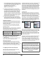
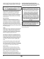
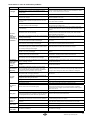
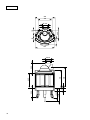
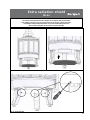
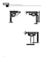
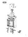
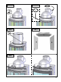
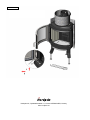
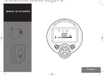
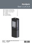
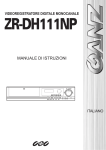
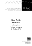
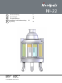
NI-22
NOBrukerveiledning
GB
User manual
DKBrugervejledning
SE Installations- och bruksanvisning 22
FI Käyttöohje
Product no: IN-00N22-xxx
Sintef no: 041-169
RRF no:
29 09 1917
Last updated: 01.01.2013
2
10
16
28
1. Prior to assembling the insert
INDEX
1. Prior to assembling the insert Chimney draught
10
10
2. Technical information 11
3. Distance to combustible material 11
4. Assembly Connection of the flue
Operating control
Painting the surround
11
12
12
12
5. Lighting the fire for the first time 12
6. Maintenance 13
Cleaning and inspection
13
Ashes13
Thermotte™13
Door and glass
13
7. Warranty
13
8. Advice on lighting a fire
14
Some advice in case of combustion problems
15
All our products are tested according to the latest
European requirements and also to the Norwegian
standard NS 3058 and NS 3059, which include
particle tests. However, several European countries
have local regulations for installation of fireplaces,
which change regularly. It is the responsibility
of the client that these regulations are complied
with in the country/region where the fireplace is
installed. Nordpeis AS is not responsible for incorrect
installation.
Important to check
(please note that this list is not exhaustive):
• distance from firebox to combustible/flammable
materials
• insulation materials/requirements between
fireplace surround and back wall
• size of floor plates in front of fireplace if required
• flue connection between firebox and chimney
• insulation requirements if flue passes through a
flammable wall
Chimney draught
Compared with older models, the clean burning
inserts of today put significantly higher demands
on the chimney. Even the best insert will not work
properly if the chimney does not have the right
dimensions or is not in good working order. The
draught is mainly controlled by gas temperature,
outside temperature, air supply as well as the height
and inner diameter of the chimney. The diameter of
the chimney should never be less than that of the flue/
chimney collar. At nominal effect there should be a
negative pressure of 12 to 25 Pascal.
The draught increases when:
• The chimney becomes warmer than the outside air
• The active length of the chimney over the hearth
increases
• Good air supply to the combustion
It can be difficult to obtain the right draught conditions
in case the chimney is too large relative to the insert,
as the chimney does not heat up well enough. In
such cases you may want to contact professional for
evaluation of possible measures. Draught that is too
strong can be controlled with a damper. If necessary,
contact a chimney sweeper.
For your own safety, comply with the assembly instructions.
All safety distances are minimum distances. Installation
of the insert must comply with the current rules and
regulations of the country where the product is installed.
Nordpeis AS is not responsible for wrongly assembled
inserts.
Subject to errors and changes.
For the latest updated version go to www.nordpeis.com.
10
GB
2. Technical information
3. Distance to combustible material
The inserts from Nordpeis all have secondary
combustion and are clean burning. The combustion
takes place in two phases: first the wood burns and
then the gases from the fumes are lit by the hot air.
This ensures that these new inserts have minimal
emissions of soot particles and un-burnt gases (such
as CO) and are thus better for the environment. Clean
burning inserts require a small amount of wood in
order to obtain a good heat output. Use exclusively
clean and dry wood. We recommend seasoned
hardwood with a maximum moisture content of 20%..
Firewall
Ensure that the safety distances are respected
(FIG 1).
When connecting a steel chimney to the top outlet use
the security distances required from the manufacturer.
Important! When placing the insert on a
combustible floor, a steel plate of at least 0.7mm
must cover the entire floor surface inside the
surround. Any flooring made of combustible
material, such as linoleum, carpets etc. must be
removed from underneath the steel plate.
Insert
NI-22
Material
Cast iron
Surface treatment
door / doorframe
Heat resistant varnish
4. Assembly
Fuel:
Wood logs, 35 cm
Operating range
6 kW
Efficiency
78,2
CO % @ 13% O2
0,08
Draught system
Ignition vent control and air
vent control
The following tools are necessary:
• 10 mm and 13 mm spanner/wrench
• Electrical drill / Phillips screwdriver (for self tapping
screws)
• Caulking gun (for the stove cement)
Combustion system
Secondary combustion
(clean burning)
Heating area
30-150 m²
Flue outlet
Top, posterior and lateral
Flue
Inner Ø 150 mm
*Alternative versions exsists due
to National requirements
Weight of insert
108 kg
Area of convection
air vent under insert
400 cm²
Area of convection
air vent over insert
600 cm²
Minimum distance
from convection air
outlet to ceiling
1. Ensure that all the loose parts are included (FIG 2):
A. Heat shield in two parts with 4 self drilling screws
B. Lid for flue outlet with fastening bracket, screw and
nut
C. Smoke dome
D. 2 fasteners with bolts and disks for the smoke
dome
E. Insert with door
F. 3 fastening bolts with disks for the legs
G.3 legs with adjusting bolts and lock nuts
H. Glove
The insert expands when in use, and for this
reason the insert must NEVER rest on the
surround, but have a gap of about 3 mm. The
insert must neither rest on the bench plate or
against the sides. It is recommended to dry
stack the surround in order to adjust the insert
prior to perforating the chimney for the flue
connection.
500mm
Flue gas temperature 310 °C
Air supply
requirements (m³/h)
18
Fuel charge
1,8kg
Refueling interval
55 min
Opening of the air
vent control
100%
Operation
Intermittent*
* Intermittent combustion refers to normal use of a fireplace, i.e. new
wood is inserted when the previous load has burned down to ember
Warning: If the requirements for ventilation are
NOT complied with, the heating circulation effect
will be considerably reduced and
overheating can occur.
This can in a worst case scenario cause a fire.
2. Carefully lay the insert on its back. Ensure that
the transportation padding is put inside the insert
before turning it over, so that the insulating plates
in the burn chamber do not fall down and break.
Please note that the insulating plates may release
coloured dust when touched. Avoid touching the
cast iron with dust on your fingers. In case of dust
on any cast iron part, the glove included is well
suited to brush it off.
Start with assembling the legs (FIG 3) as follows:
• Fasten the screws on to the insert with a 13 mm
spanner/wrench. The legs are placed as shown
(the opening in the legs should face outwards).
GB
11
• Use the adjusting bolts (FIG 4) and adjust the legs
to the desired height (X) before returning the insert
to an upright position (do not tilt the insert). The
height depends on the surround.
Regulation of leg height (X) for NI-22:
From: 240 mm To: 380 mm.
3. Install the smoke dome (FIG 5A). The dome is
assembled with a fastener on each side. Use a 10
mm spanner/wrench and the fastening disks and
bolts that are included with the insert. The lid for
the smoke dome is normally already mounted on
the top for a posterior connection. If the fireplace
will be connected to a chimney at the top, move the
smoke lid to the rear flue outlet (FIG 5B). Use the
parts as shown in the illustration.
4. Install the heat shield around the smoke dome
(FIG 6). The heat shield comes in two parts that
are fastened with 4 self-drilling screws. Fasten the
heat shield so that the flue can be connected later.
Connection of the flue
Please be aware when connecting the 150 mm flue
to the smoke dome that the flue is placed outside the
flue outlet collar. *Alternative versions exsists due to
National requirements
For the flue connection to the chimney, follow the
recommendations from the chimney manufacturer.
Air vent control (top
right corner)
Pushed in = closed
Pulled out = open
Left position = closed
Right position = open
Lighting a fire
Insert small dry pieces of kindling wood, ignite and
ensure that the flames have a good grip of the wood
before closing the door. Open the ignition vent control
(Fig A) as you close the door. When the flames are
stable and the chimney is warm, close the ignition
vent control. If it is not closed the insert and chimney
may overheat. The air supply is then regulated with
the air vent control. (Fig B). NB! If the draught is low
after the fire has been lit, additional air supply can be
added by opening the ignition vent control.
FIG A
Operating control
When the insert is in an upright position, and prior to
mounting the surround, check that all functions are
easy to manoeuvre and appear satisfactory.
Ignition vent control
(bottom right corner)
insulation plates which can result in a slower burn rate
the first few times the insert is used. These will be
resolved once the humidity has evaporated. Possibly
leave the door slightly open the first 2-3 times that the
insert is used. It is advisable to ventilate the room
well when firing for the first time as the varnish
on the product may release some smoke or smell.
Both the smoke and smell will disappear and are not
hazardous.
Ignition vent control
Air vent control
When there is a glowing layer of ash, new wood logs
can be inserted. Pull the hot ember to the front of the
combustion chamber when inserting new logs so that
the wood is ignited from the front. Keep the door
slightly open each time new logs are inserted so that
the flames get established. The fire should burn with
bright and lively flames.
Removing the self-closing mechanism FIG 9
(this applies only to the panoramic door)
1. Open the door.
2. Use a pair of pliers and grab the long piece on the
spring. Gently pull the spring down and off.
Painting the surround
It is recommended to use the insert a few times in
order to let the varnish harden before any eventual
masking and painting. Only use water based emulsion
paint and a designated masking tape. Carefully
remove the tape in order not to damage the varnish.
Using the insert with low combustion effect and firing
around the clock increase pollution as well as the
risk for a fire in the chimney. Never allow the insert
or flue to become glowing red. Turn off the air vent
control should this happen. Regulation of the air vent
control takes some experience, but after a little while
a natural rhythm for the fire will be found.
IMPORTANT! Always remember to open the air
vent control (preferably also the door) before
new wood logs are inserted into a hot burn
chamber. Let the flames get a good grip on the
wood before the air control setting is reduced.
When the draught in the chimney is low and the
vent is closed, the gas from the firewood can be
ignited with a bang. This can cause damages
to the product as well as the immediate
environment.
5. Lighting the fire for the first time
When the insert is assembled and all instructions
have been observed, a fire can be lit.
Take care when inserting logs into the burn chamber,
in order not to damage the Thermotte plates. Please
note that there might be some humidity in the
12
FIG B
GB
6. Maintenance
when the glass is cold.
Cleaning and inspection
The insert should be inspected thoroughly and
cleaned at least once per season (possibly in
combination with the sweeping of the chimney and
chimney pipes). Ensure that all joints are tight and
that the gaskets are rightly positioned. Exchange any
gaskets that are worn or deformed.
Check regularly that the transition between the glass
and the door is completely tight. Possibly tighten the
screws that hold the glass in place - but not too hard,
as this can cause the glass to crack.
Periodically, it may be necessary to change the
gaskets on the door to ensure that the burn chamber
is air tight and working optimally. These gaskets can
be bought as a set, usually including ceramic glue
Remember that the insert must always be cold when
inspected.
Ashes
The ashes should be removed at regular intervals.
Be aware that the ashes can contain hot ember even
several days after the fire is finished. Use a container
of non-combustible material to remove the ashes. It is
recommended to leave a layer of ashes in the bottom
as this further insulates the burn chamber. Take
care with the Thermotte plates when the ashes are
removed, particularly when using an ash shovel, so as
not to damage them.
Thermotte™
These insulating plates in the burn chamber contribute
to a high combustion temperature, which leads to
cleaner combustion of the wood and a higher rate of
efficiency. Any fissures in the plates will not reduce
their insulation efficiency.
If new plates are needed, contact your dealer.
In case the plates need to be replaced, lift the smoke
baffle (1) in order to remove the side plates.
Should it be necessary to unhook the door/doors,
unscrew the lid (FIG 8) above the air vent control.
The lid is fastened underneath with 3 screws / Allen
screws. When the lid is removed, the door/doors are
free to unhook.
CERAMIC GLASS
CANNOT BE
RECYCLED
Ceramic glass should
be disposed of as residual waste, together with
pottery and porcelain
* When exchanging the smoke baffle (part 1), the steel bracket
must be removed and fastened on to the new one prior to
assembly.
Recycling of the ceramic glass
Ceramic glass cannot be recycled. Old glass, breakage or otherwise unusable ceramic glass must be
discarded as residual waste. Ceramic glass has a
higher melting temperature, and can therefore not be
recycled together with glass. If mixed with ordinary
glass, it would damage the raw material and could, in
worst case end the recycling of glass. It is an important contribution to the environment to ensure that
ceramic glass does not end up with the recycling of
ordinary glass.
Please note: Wood logs that are too long can cause
additional strain and crack the plates, due to the
tension created between the side plates.
Packaging Recycle
The packaging accompanying the product should be
recycled according to national regulations.
1. Smoke baffle*
2. Left side plate
3. Right side plate
Please also note that the Thermotte plates may
release coloured dust when touched. Avoid touching
any cast iron parts with dust on your fingers. Any
visible dust on cast iron can be brushed off with the
glove that is included.
Door and glass
Should there be any soot on the glass it may be
necessary to clean it. Use dedicated glass cleaner,
as other detergents may damage the glass. (NB! Be
careful, even dedicated glass cleaner can damage the
varnish on the door frame). A good advice for cleaning
the glass is to use a damp cloth or kitchen roll paper
and apply some ash from the burn chamber. Rub
around the ash on the glass and finish off with a piece
of clean and damp kitchen roll paper. NB! Only clean
7. Warranty
For detailed description of the warranty
conditions see the enclosed warranty card or visit
our website www.nordpeis.com
The CE mark is placed on the side of the insert.
8. Advice on lighting a fire
The best way to light a fire is with the use of lightening
briquettes and dry kindling wood. Newspapers
cause a lot of ash and the ink is damaging for the
environment. Advertising flyers, magazines, milk
GB
13
exceed the temperatures determined safe.
Burning briquettes/ compact wood is done so at
your own risk and only small amounts (max 1/3 of
normal load) should be used for each load.
cartons and similar are not suitable for lighting a fire.
Good air supply is important at ignition. When the flue
is hot the draught increases and door can be closed.
Warning: NEVER use a lighting fuel such as
petrol, karosine, alcohol or similar for lighting
a fire. This could cause injury to you as well
as damaging the product.
Warning:
NEVER use impregnated wood, painted wood,
plywood, chipboard, rubbish, milk cartons,
printed material or similar. If any of these items
are used as fuel the warranty is invalid.
Use clean and dry wood with a maximum moisture
content of 20%. The wood should be dried for a
minimum of 6 months after it is cut. Humid wood
requires a lot of air for the combustion, as extra
energy/heat is required for drying the humid wood and
the heat effect is therefore minimal. This in addition
creates soot in the chimney with the risk of creosote
and chimney fire.
Storing of wood
In order to ensure that the wood is dry, the tree
should be cut in winter and stored during the summer,
covered and in a location with adequate ventilation.
The wood pile must never be covered by a tarpaulin
lying against the ground as the tarpaulin will then act
as a sealed lid that will prevent the wood from drying.
Always keep a small amount of wood indoors for a few
days before use so that moisture in the surface of the
wood can evaporate.
Usage
Not enough air to the combustion may cause the glass
to soot. Hence, supply the fire with air just after the
wood is added, so that the flames and gases in the
combustion chamber are properly burnt. Open the air
vent and have the door slightly ajar in order for the
flames to establish properly on the wood.
Common to these materials is that during
combustion they can form hydrochloric
acid and heavy metals that are harmful to
the environment, yourself and the insert.
Hydrochloric acid can also corrode the steel in
the chimney or masonry in a masonry chimney.
Also, avoid burning with bark, sawdust or other
extremely fine wood, apart from when lighting
a fire. This form of fuel can easily cause a
flashover that can lead to temperatures that are
too high.
Warning:
Make sure the insert is not overheated - it can
cause irreparable damage to the product. Such
damage is not covered by the warranty.
Source “Håndbok, effektiv og miljøvennlig vedfyring” by Edvard
Karlsvik SINTEF Energy Research AS and Heikki Oravainen, VTT.
http//www.eufirewood.info
Note that the air supply for the combustion also can
be too large and cause an uncontrollable fire that very
quickly heats up the whole combustion chamber to an
extremely high temperature (when using with a closed
or nearly closed door). For this reason you should
never fill the combustion chamber completely with
wood.
It is recommended to keep an even fire with a small
amount of wood. Too many logs put on hot ember,
may result in combustion air starvation, and the gases
will be released unburnt. For this reason it is important
to increase the air supply just after adding logs.
Choice of fuel
All types of wood, such as birch, beech, oak, elm,
ash and fruit trees, can be used as fuel in the insert.
Wood species have different degrees of density - the
more dense the wood is, the higher the energy value.
Beech, oak and birch has the highest density.
Attention! We do not recommend using fuel
briquettes/ compact wood in our products. Use of
such fuel may cause the product to overheat and
14
GB
Some advice in case of combustion problems
Error
Explanation
Solution
The chimney is blocked.
No draught
The flue is sooty or there is accumulated soot on the
smoke baffle.
Contact a chimney sweeper / dealer for more information or clean
the flue, smoke baffle and burn chamber.
The smoke baffle is wrongly positioned.
Verify the assembly of the smoke baffle - see assembly instructions.
Downdraught in the room caused by no draught, that the
house is too “air tight”.
Light the fire with an open window. If this helps, more/bigger vents
must be installed in the room.
Downdraught in the room – caused by extractor and/or
central ventilation system that pulls too much air out of
the room.
Turn off/regulate extractor and/or other ventilation. If this helps,
more vents must be installed.
The flues from two fireplaces/stoves are connected to
the same chimney at the same height.
One flue must be repositioned. The height difference of the two flue
pipes must be of at least 30 cm.
The flue is in a declining position from the smoke dome
to the chimney.
The flue must be moved so that there is an inclination of at least
10º from smoke dome to chimney. Possibly install a smoke suction
device*.
The flue is too far into the chimney.
The flue must be reconnected so that it does not enter into the
chimney but ends 5 mm before the chimney inner wall. Possibly
install a smoke suction device*.
Soot hatch in the basement or attic that is open and thus
creating a false draught.
Soot hatches must always be closed. Hatches that are not tight or
are defected must be changed.
Damper/top draught vents or doors on fireplaces that are
not in use are open and create a false draught.
Close damper, doors and top draught vents on fireplaces that are
not in use.
An open hole in the chimney after that a fireplace has
been removed, thus creating a false draught.
Holes must be completely sealed off with masonry.
Defect masonry in the chimney, e.g. it is not airtight
around the flue pipe entry and/or broken partition inside
the chimney creating a false draught.
Seal and plaster all cracks and sites that are not tight.
The cross-section in the chimney is too large which
results in no or very low draught.
The chimney must be refitted, possibly install a smoke suction
device*.
The cross-section in the chimney is too small and the
chimney cannot carry out all the smoke.
Change to a smaller fireplace or build new chimney with a larger
cross section. Possibly install a smoke suction device*.
The chimney is too low and hence a poor draught.
Increase the height of the chimney and/or install a chimney cap/
smoke suction device*.
The chimney is too low in relationship to the surrounding
terrain, buildings, trees etc.
Increase the height of the chimney and/or install a chimney cap/
smoke suction device*.
Turbulence around the chimney due to the roof being
too flat.
Increase the height of the chimney and/or install a chimney cap/
smoke suction device*.
The fireplace combustion receives too much oxygen
due to a leakage under the lower border of the insert
or too strong chimney draught. Difficult to regulate the
combustion and the wood burn up too quickly.
Any possible leakage must be sealed off. A draught regulator or
possibly a damper can reduce the chimney draught. NB! A leakage
of only 5 cm2 is enough for 30% of the heated air to disappear.
The smoke buffer is wrongly positioned.
Verify the positioning of the smoke buffer – see assembly
instructions.
In case of using oven-dried wood, this requires less air
supply than when using normal wood.
Turn down the air supply.
The gaskets around the door are worn and totally flat.
Replace the gaskets, contact your dealer.
The chimney is too large.
Contact chimneysweeper or other professional for more details.
The wood is too wet.
Only use dry wood with a humidity of maximum 20%.
The air vent control is closed too tightly.
Open the air vent control to add air to the combustion. When new
wood logs are inserted all vent controls should be completely
opened or the door slightly opened until the flames have a good
take on the wood.
Bad combustion (the temperature is too low)
Follow the guidelines in this user guide for correct combustion.
White glass
Using wrong material for combustion (such as: painted
or impregnated wood, plastic laminate, plywood etc)
Ensure to use only dry and clean wood.
Smoke is
released when
the door is
opened
A levelling out of pressure occurs in the burn chamber.
Open the air vent control for about 1 min before opening the door
– avoid opening the door too quickly.
The door is opened when there is a fire in the burn
chamber.
Open the door carefully and/or only when there is hot ember.
The combustion temperature is too low.
Increase the air supply.
The wood is humid and contains water damp.
Ensure to use only dry and clean wood.
Insufficient combustion.
Increase the air supply.
The insert
release
smoke when
lighting the
fire and during
combustion
The fireplace
releases smoke
inside when
it is windy
outside.
The fireplace
does not heat
sufficiently.
Too much
draught
The glass is
sooty
White smoke
Black or grey/
black smoke
GB
*Electric top chimney fan
15
NI-22 = mm
562
392
Ø 148
162
50
265
114
Ø 136
530
Ø148
34
> 240
< 380
298
88
625
440
516
295
Ø136
Extra radiation shield
NI-22
NB! Bei der Montage in Deutschland, Österreich oder der Schweiz muss zusätzliches StrachlungsDet ekstra
varmeskjoldet skal kun brukes når innsatsen har panoramadør
blech verwendet
werden.
This radation shield is only to be used when the insert has a panoramic door
NB! Écran de chaleur supplémentaire doit être utilisé pour assemblage en France.
Ylimääräistä säteilysuojaa käytetään vain panoraamaluukkujen kanssa
Skal endastdeve
användas
när
innsatsen
panoramadör
NB! Scudo termico addizionale
essere
utilizzato
perhar
montaggio
in Italia.
Art.no: 22-01014-004
01.09.2009
35
FIG 1
=Brannmur/Brandmur/Turvaetäisyydet/Firewall
=Brennbart materiale/Brændbart materiale/ Brännbart material/ Palavasta materiaalista/Combustible material
>915
>800
>1140
>3
00
>20
>20
>20
>1000
>20
>600
36
FIG 2
X4
F
F
F
G
G
G
H
37
FIG 3
FIG 4
X
38
FIG 5A
FIG 5B
X2
UNLESS OTHERWISE SPECIFIED:
DIMENSIONS ARE IN INCHES
TOLERANCES:
FRACTIONAL
ANGULAR: MACH
BEND
TWO PLACE DECIMAL
THREE PLACE DECIMAL
INTERPRET GEOMETRIC
TOLERANCING PER:
PROPRIETARY AND CONFIDENTIAL
THE INFORMATION CONTAINED IN THIS
DRAWING IS THE SOLE PROPERTY OF
<INSERT COMPANY NAME HERE>. ANY
REPRODUCTION IN PART OR AS A WHOLE
WITHOUT THE WRITTEN PERMISSION OF
<INSERT COMPANY NAME HERE> IS
PROHIBITED.
5
MATERIAL
NAME
APPLICATION
TITLE:
CHECKED
MFG APPR.
Q.A.
COMMENTS:
SIZE DWG. NO.
REV
NI-22 A
assembly panorame
.
USED ON
NEXT ASSY
DATE
DRAWN
ENG APPR.
FINISH
3
FIG 6
SHEET 1 OF 1
SCALE: 1:1 WEIGHT:
DO NOT SCALE DRAWING
4
2
1
FIG 7
X4
FIG 8
39
FIG 9
Nordpeis AS, Gjellebekkstubben 11, N-3420 LIERSKOGEN, Norway
www.nordpeis.no