1
ADC-200/212/216
PC Oscilloscopes
User's Manual
adc200.en r4
Copyright © 1995-2015 Pico Technology Ltd. All rights reserved.
I
Contents
Contents
1 Introduction ................................................................................................................................ 1
1 Connecting to the PC .......................................................................................................................... 1
2 Safety warning .................................................................................................................................... 3
2 Product features ......................................................................................................................... 4
1 Specifications ...................................................................................................................................... 4
2 Equivalent Time Sampling (ETS) .......................................................................................................... 5
3 Principles of operation ........................................................................................................................ 5
3 Driver formats & routines ........................................................................................................... 8
1 Driver formats .................................................................................................................................. 10
1 Windows 32-bit driver .................................................................................................................................................. 10
2 Linux driver ................................................................................................................................................................... 10
2 Functions .......................................................................................................................................... 10
1 adc200_get_driver_version ............................................................................................................................................ 10
2 adc200_open_unit ......................................................................................................................................................... 11
3 adc200_set_unit ............................................................................................................................................................ 11
4 adc200_close_unit ......................................................................................................................................................... 12
5 adc200_has_relays ......................................................................................................................................................... 12
6 adc200_set_dc ............................................................................................................................................................... 12
7 adc200_set_range ......................................................................................................................................................... 13
8 adc200_set_channels ..................................................................................................................................................... 14
9 adc200_set_oversample ................................................................................................................................................ 14
10 adc200_set_timebase .................................................................................................................................................. 15
11 adc200_set_time_units ................................................................................................................................................ 16
12 adc200_set_trigger ...................................................................................................................................................... 17
13 adc200_set_rapid ........................................................................................................................................................ 18
14 adc200_max_samples .................................................................................................................................................. 19
15 adc200_run ................................................................................................................................................................. 19
16 adc200_ready .............................................................................................................................................................. 20
17 adc200_stop ................................................................................................................................................................ 20
18 adc200_get_values ...................................................................................................................................................... 20
19 adc200_get_times_and_values ..................................................................................................................................... 21
20 adc200_get_overflow .................................................................................................................................................. 22
21 adc200_get_single ....................................................................................................................................................... 22
22 adc200_get_unit_info .................................................................................................................................................. 23
23 adc200_get_status ....................................................................................................................................................... 24
24 adc200_get_product .................................................................................................................................................... 25
25 adc200_get_max_ets ................................................................................................................................................... 25
26 adc200_get_ets_time ................................................................................................................................................... 25
27 adc200_set_ets ............................................................................................................................................................ 26
adc200.en r4
Copyright © 1995-2015 Pico Technology Ltd. All rights reserved.
ADC-200 Series User's Guide
II
28 adc200_set_frequency ................................................................................................................................................. 26
4 Programming support ............................................................................................................... 27
1 C (Windows) .................................................................................................................................... 27
2 Visual Basic ....................................................................................................................................... 27
3 Delphi .............................................................................................................................................. 28
4 Excel ................................................................................................................................................ 28
5 Agilent-Vee ....................................................................................................................................... 28
6 LabVIEW ......................................................................................................................................... 28
5 Glossary .................................................................................................................................... 29
Copyright © 1995-2015 Pico Technology Ltd. All rights reserved.
adc200.en r4
1
1
Introduction
Introduction
This manual covers the ADC-200, ADC-212 and ADC-216 products. Where information
applies equally to all three product groups, the abbreviation ADC-2xx is used.
The ADC-2xx products are high-speed analog-to-digital converters (ADCs) with two
input channels and software-controlled input ranges. They can be used as PC-based
oscilloscopes / spectrum analyzers with the supplied PicoScope software or as data
loggers with the PicoLog software; alternatively, you can use the ADC-2xx driver
software to develop your own programs to collect and analyze data from the unit.
The ADC-2xx package contains the following items:
ADC-2xx unit
25 way parallel port cable
power supply (12 volt @ 500 mA)
software CD
installation guide
1.1
Connecting to the PC
The ADC-2xx can be connected to the PC in two ways:
directly to a parallel port (printer port) on the computer
to a USB port on the computer, via a Pico USB parallel port adapter
Parallel port operation
When you install the application software from the Pico CD, the computer will ask you
which port to use. Select LPT1, LPT2 or LPT3 (Note: you can change the port at a later
stage if you need to).
To use the ADC, connect it to the parallel port on your computer, using a the 25-way
cable provided.
USB Parallel port operation
USB printer port interfaces are not suitable for use with Pico products. If you wish to
connect a Pico product to a USB port, you will need a Pico USB Parallel Port adapter.
When you install the application software from the Pico CD:
1. the computer asks you which port to use, select USB-PP1
2. once the USB driver software is installed, connect the Pico USB parallel port adapter
to your PC: the computer will automatically configure the drivers
Checking the installation
1. Connect DC power by plugging the power adapter into a mains socket and plugging
the DC power jack into the socket on the ADC-2xx. The red light should now be on,
showing that the unit is powered. The light may switch off when data is not being
processed.
2. To check that the unit is working, start up PicoScope. PicoScope should now display
the voltage that you have connected. If you are using scope probes, when you
touch the scope probe tip with your finger, you should see a small 50 Hz mains
signal.
adc200.en r4
Copyright © 1995-2015 Pico Technology Ltd. All rights reserved.
ADC-200 Series User's Guide
2
The ADC-2xx has the same connectors as an oscilloscope, so you can use standard
oscilloscope probes. The input impedance is also the same, so the x10 function on a
scope probe works correctly.
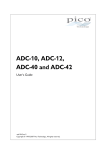
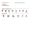
The BNC connector labelled 4 below ('E' on the unit) has two functions; in normal use
it is the external trigger input and accepts a TTL compatible signal. This connector can
also be used as a simple (square wave) generator. This signal generator can be used
to compensate x10 scope probes.
Connector diagram
1.
2.
3.
4.
D25 Parallel port connector
DC 12 volt @ 500 mA power socket
'Running' LED
External trigger/Signal generator
Copyright © 1995-2015 Pico Technology Ltd. All rights reserved.
adc200.en r4
3
1.2
Introduction
Safety warning
We strongly recommend that you read the general safety information below before
using your product for the first time. If the equipment is not used in the manner
specified, then the protection provided may be impaired. This could result in damage
to your computer and injury to yourself or others.
Maximum input range
The ADC-2xx product is designed to measure voltages in the range –20V to +20V.
Any voltages in excess of ±100V may cause permanent damage to the units.
Mains voltages
No Pico products are designed for use with mains voltages. To measure mains we
recommend the use of a differential isolating probe specifically designed for such
measurements.
Safety grounding
The ground of every product is connected directly to the ground of your computer via
the provided interconnecting cable. This is done in order to minimize interference.
Always use the provided cable to attach the product to your computer.
As with most oscilloscopes and data loggers, you should take care to avoid connecting
the ground input of the product to anything which may be at some voltage other than
ground. If in doubt, use a meter to check that there is no significant AC or DC
voltage. Failure to check may cause damage to the product and computer and could
cause injury to yourself or others.
You should assume that the product does not have a protective safety earth.
Misconfiguration and/or use on voltages outside the maximum input range can be
hazardous.
Repairs
The unit contains no user serviceable parts: repair or calibration of the unit requires
specialized test equipment and must be performed by Pico Technology Limited or their
authorized distributors.
adc200.en r4
Copyright © 1995-2015 Pico Technology Ltd. All rights reserved.
ADC-200 Series User's Guide
4
2
Product features
2.1
Specifications
Product
Resolution / bits
Input Channels
External Trigger
Voltage Ranges
ADCADCADCADCADCADCADC200/20 200/50 200/100 212/3 212/50 212/100 216
8
12
16
2 x BNC connectors
1 MΩ impedance
AC/DC coupling
Ext BNC
Input: TTL Level Trigger
Output: Square Wave Signal Generator
±50 mV to ±20 V
in 1,2,5 Steps (in 9 Ranges)
ADC-212/3 and ADC-216 also have
±20 mV and ±10 mV Ranges
±3
±1
±100
Accuracy / %
Overload Protection / V
Sampling Rate / Samples/s
1 Channel
2 Channel
Repetitive
Signal with ETS
Buffer Size / kSamples
Signal Generator
Power Supply
Dimensions / mm
Copyright © 1995-2015 Pico Technology Ltd. All rights reserved.
20M
10M
50M
50M
8
16
100M
50M
3M
1.5M
50M
50M
5G
100M
50M
5G
32
32
128
128
<250 kHz TTL square wave
12 V DC nominal at 500 mA max
DC 1.3 mm connector (center positive)
140 x 190 x 45
333k
166k
32
adc200.en r4
5
2.2
Product features
Equivalent Time Sampling (ETS)
Equivalent time sampling (ETS) is a way of increasing the effective sample rate when
working with repetitive signals. It is not possible to use ETS with one-shot signals.
ETS works because the trigger event can be assumed to be asynchronous with respect
to the sampling clock. If the unit collects blocks of data from 100 successive trigger
events, there should be a reasonable spread of time intervals between the trigger
event and the next sample. If the unit records this time interval from each cycle, the
computer can interleave the samples from successive blocks to give approximately 100
times the sampling rate.
Because the time interval between the trigger event and the next is somewhat
random, there is likely to be bunching in some areas and gaps in others. In order to
get a reasonable distribution, it is necessary to collect, say, 300 blocks, then to select
the best 100 from them.
ETS is managed using three routines:
adc200_get_max_ets - this indicates the maximum number of ETS interleaves
allowed: it will be zero if the particular unit in use does not support ETS.
adc200_get_ets_time - get the time per sample when running in ETS mode
adc200_set_ets - set the interleave and max cycles
The minimum equivalent sample time can be calculated as:
adc200_get_ets_time() / adc200_get_max_ets()
For example, for a 20 ns sample time and max interleave of 100, the minimum
equivalent sample time is 200 ps, which corresponds to 5 GS/s.
Notes:
1. When using ETS, the samples are not evenly spaced. The use of
adc200_get_times_and_values (rather than adc200_get_values) is therefore
essential.
2. When ETS is enabled, adc200_set_timebase is ignored.
2.3
Principles of operation
This section explains how the ADC-2xx works. This information is intended for people
writing their own software and is not required if you are only using the product with
PicoScope or PicoLog software.
The ADC-2xx range includes both high-speed analog-to-digital converters (eg ADC200/100) and high-resolution converters (eg ADC-216). These devices take sequences
of voltage measurements and feed the information into a computer.
Block sampling
When running at high speeds, the ADC-2xx can collect data much faster than the PC
can read it, so the ADC-2xx reads in a block of data into internal memory, then
transfers it to the PC once the block is completed. At very low speeds, it may be
unacceptable to wait until the block is completed before being able to inspect the first
few readings. Therefore in addition to the Fast mode, the driver routine:
adc200_get_single, is provided to obtain single readings.
adc200.en r4
Copyright © 1995-2015 Pico Technology Ltd. All rights reserved.
ADC-200 Series User's Guide
6
Fast mode
In fast mode, the computer starts the ADC-2xx to collect a block of data into its
internal memory. When the ADC has collected the whole block, the computer stops the
ADC and transfers the whole block into computer memory.
The maximum number of values depends upon the size of the ADC-2xx memory. The
unit can sample at a number of different rates which are the clock frequency divided
by powers of two (half, quarter, eighth, etc). There are between 16 and 20 sampling
rates, depending on the ADC-2xx model.
There is a separate buffer for each channel: on the faster models, one input can be
routed into both buffers, thus doubling the effective sampling rate.
The ADC-2xx driver normally performs a number of setup operation before collecting
each block of data. This can take up to 50 milliseconds. If it is necessary to collect
data with the minimum time interval between blocks, use the adc200_set_rapid
option.
adc200_get_single
The adc200_get_single routine provides a way of collecting a single reading
averaged from a number of samples. This can be used instead of Fast mode, where
the screen needs to be updated regularly.
Triggering
The ADC-2xx can either start collecting data immediately, or it can be programmed to
wait for a trigger event to occur with the adc200_set_trigger routine. The trigger
event can occur when the channel A or B input crosses a threshold voltage, or on a
change of state of the external (digital) trigger input. The trigger event can be either a
rising or a falling edge.
The ADC-2xx can be programmed to place the trigger event at the beginning of the
buffer, like an analog scope, or at the end of the buffer (pre-trigger), or any point in
between.
The external trigger input is the same as the signal generator output, so these two
functions cannot be used at the same time.
Voltage ranges
It is possible to set the gain for each channel with the adc200_set_range routine, to
give an input voltage range from 50 mV to 20 V (10 mV to 20 V for the ADC-212/3
and ADC-216).
AC/DC operation
Test whether the ADC can set the AC/DC switch through software, using the
adc200_has_relays routine. Using the adc200_set_dc routine, each channel can
be set to either AC or DC coupling. When AC coupled, any DC component of the signal
is filtered out. For some older versions, there is a physical AC/DC switch for each
channel on the front of the unit: for newer versions, it is controlled by software.
Oversampling
When the unit is operating at speeds below maximum, it is possible to oversample
with adc200_set_oversample - to take more than one measurement during each time
interval. This reduces the effects of aliasing, and increases the apparent resolution of
the ADC.
Copyright © 1995-2015 Pico Technology Ltd. All rights reserved.
adc200.en r4
7
Product features
Scaling
The ADC-200 is an 8-bit ADC, which returns a value between 0 and 255 to represent
the currently selected voltage range. To facilitate software development, the numbers
are adjusted so that 0 ADC counts corresponds to 0 volts. All values returned by the
driver are scaled as if 16x oversampling is selected, so the maximum positive voltage
in the selected range is represented by 2047 and the maximum negative voltage by 2048.
The ADC-212 is a 12-bit ADC, which returns a value between 2047 and –2048
regardless of the oversampling selected..
The ADC-216 is a 16-bit ADC, which returns a value between 32767 and –32768.
Signal generator
The ADC-2xx has a built-in signal generator which may be set using
adc200_set_frequency. It produces a selection of accurate frequencies from 1 kHz to
250 kHz. These are selected under software control. The waveform is approximately
square at low frequencies, but it rounds off above about 100 kHz.
The signal generator output is the same as the signal generator input, so these two
functions cannot be used at the same time.
Multi-unit operation
It is possible to collect data using up to three ADC-2xx units at the same time. Each
ADC-2xx must be connected to a separate parallel port. The routine adc200_set_unit
select which unit the driver should access next.
For example, to collect data from units on LPT1 and LPT3 at the same time:
adc200_open (1)
adc200_open (3)
adc200_set_unit (1)
... set up unit 1
adc200_run
adc200_set_unit (3)
... set up unit 3
adc200_run
ready = FALSE
while not ready
adc200_set_unit (1)
ready = adc200_ready
adc200_set_unit (3)
ready = ready & adc200_ready ()
adc200_set_unit (1)
adc200_get_values
adc200_set_unit (3)
adc200_get_values
adc200.en r4
Copyright © 1995-2015 Pico Technology Ltd. All rights reserved.
ADC-200 Series User's Guide
3
8
Driver formats & routines
Formats
The drivers are available in two formats:
Windows XP/Vista DLL
Linux driver
Functions
The driver contains the following functions:
Copyright © 1995-2015 Pico Technology Ltd. All rights reserved.
adc200.en r4
9
Driver formats & routines
Function
Description
adc200_get_driver_version
adc200_open_unit
adc200_set_unit
Determine the driver version
Open an ADC-2xx unit
Switch to the ADC-2xx on a different port (multi-unit
operation only)
Shut down an ADC-2xx unit
Find out whether the ADC-2xx has software-controlled AC/DC
switches
Set the AC/DC switch
Set the input voltage range
Specify channels to use (A, B, Both)
Specify the oversample factor
Set the time interval between samples
Set the units for times (default ps)
Specify the triggering parameters
Enable rapid block repeat mode
Find out how many samples can be taken, using current
settings
Start the ADC-2xx collecting data
Find out whether the ADC-2xx has collected some data
Stop the ADC-2xx
Get a block of samples from the ADC-2xx
Get a block of samples and the times at which they were
taken
Determine whether an overflow occurred during the last
adc200_get_values operation
Get a single value from each channel
If open failed, get fault info. If open succeeded, get unit
details
Get the error code from the most recent adc200_open_unit
operation
Find out what type of unit (200/212/216) is connected
Get the maximum ETS interleave
Get the time per sample in ETS mode
Set ETS parameters
Controls the signal generator
adc200_close_unit
adc200_has_relays
adc200_set_dc
adc200_set_range
adc200_set_channels
adc200_set_oversample
adc200_set_timebase
adc200_set_time_units
adc200_set_trigger
adc200_set_rapid
adc200_max_samples
adc200_run
adc200_ready
adc200_stop
adc200_get_values
adc200_get_times_and_values
adc200_get_overflow
adc200_get_single
adc200_get_unit_info
adc200_get_status
adc200_get_product
adc200_get_max_ets
adc200_get_ets_time
adc200_set_ets
adc200_set_frequency
Sequence of calls
The C sample program, a200con.c, show how to use all of the functions of the driver,
and includes examples showing each mode of operation.
This is the general procedure for reading and displaying a block of data:
1.
2.
3.
4.
5.
6.
7.
8.
9.
10.
adc200.en r4
open the ADC-2xx
select ranges until the required mV range is located
set AC/DC switches, channels, trigger and oversampling
select timebases until the required ns per sample is located
set the signal generator frequency (if required)
start the ADC-2xx running
wait till the ADC-2xx says that it is ready
stop the ADC-2xx
transfer the block of data from the ADC
display the data
Copyright © 1995-2015 Pico Technology Ltd. All rights reserved.
ADC-200 Series User's Guide
3.1
Driver formats
3.1.1
Windows 32-bit driver
10
The Windows XP/Vista driver, adc200.sys, is installed in Windows. This file is
normally loaded when you install the software. To check that the driver is loaded:
1.
2.
3.
4.
5.
6.
Press the Start button
Select Settings
Select Control panel
Select System
Choose the Device manager tab
Check that ADC-2xx is present and marked as started
If not, check that the driver is present and then use the regdrive.exe program
which is copied into the Pico directory. Type in:
regdrive adc200
The Windows 32-bit drivers are accessed using the file ADC20032.DLL, which is
installed in the Examples subdirectory. The DLL uses STDCALL linkage conventions,
and undecorated names.
Note: The Windows XP/Vista driver does not have access to the actual base addresses
for the parallel ports. It assumes that they are:
LPT1
LPT2
LPT3
0x278
0x378
0x3BC
If your computer does not conform to this standard, you should enter the port number
corresponding to the actual port base address in the adc200_open_unit call.
3.1.2
Linux driver
See the man information in the adc200.tar file for more information.
3.2
Functions
3.2.1
adc200_get_driver_version
unsigned short adc200_get_driver_version (void)
If it is possible that your software might be used with other drivers, you can use this
routine to determine whether the driver is more recent than the one the that you used
to develop the software.
Arguments
None
Returns
16-bit code that identifies the driver version. The upper byte contains the major
version, and the lower byte contains the minor version.
Copyright © 1995-2015 Pico Technology Ltd. All rights reserved.
adc200.en r4
11
3.2.2
Driver formats & routines
adc200_open_unit
unsigned short adc200_open_unit (unsigned short port)
This routine opens the ADC-2xx on the specified port. The initialization process takes a
couple of seconds.
Arguments
port
The number of the parallel port that the ADC2xx is connected to (1 for LPT1,
2 for LPT2, etc ... 101 for USB-PP1, 102 for USB-PP2, etc - USB ports are
named in the order they were connected in)
Returns
TRUE if successful or FALSE if unsuccessful.
The driver can handle up to three ADC-2xx units at the same time. If you wish to use
more than one unit, call adc200_open_unit once for each unit, then call
adc200_set_unit to select which unit to use next.
Note: for the Windows version, the ADC-2xx does not have access to the actual base
addresses for the parallel ports. It assumes that they are:
LPT1
LPT2
LPT3
0x278
0x378
0x3BC
If your computer does not conform to this standard, you should enter the port number
corresponding to the actual port base address.
3.2.3
adc200_set_unit
unsigned short adc200_set_unit (unsigned short port)
The driver can handle up to three ADC-2xx units at the same time: if you wish to use
more than one unit, call adc200_open_unit once for each unit, then call
adc200_set_unit to select which unit to access next.
Arguments
port
The number of the parallel port that the ADC-2xx is connected to (1 for
LPT1, 2 for LPT2, etc ... 101 for USB-PP1, 102 for USB-PP2, etc - USB ports
are named in the order they were connected in)
Returns
TRUE if successful or FALSE if unsuccessful.
adc200.en r4
Copyright © 1995-2015 Pico Technology Ltd. All rights reserved.
ADC-200 Series User's Guide
3.2.4
12
adc200_close_unit
void adc200_close (unsigned short port)
This routine stops the specified ADC-2xx and powers the unit down.
Arguments
port
The number of the parallel port that the ADC-2xx is connected to (1 for
LPT1, 2 for LPT2, etc ... 101 for USB-PP1, 102 for USB-PP2, etc - USB ports
are named in the order they were connected in)
Returns
Nothing
3.2.5
adc200_has_relays
short adc200_has_relays (void)
This routine determines whether the ADC-2xx unit has relays to control the AC/DC
switches.
Use adc200_set_dc to set the relay.
Arguments
None
Returns
TRUE if the adc200_set_dc routine can be used to set the AC/DC switches, otherwise
it returns FALSE.
3.2.6
adc200_set_dc
unsigned short adc200_set_dc
(
unsigned short channel,
unsigned short dc
)
This routine specifies the position of the AC/DC switch.
Use adc200_has_relays to determine if this routine will work with the ADC.
Arguments
channel
Use A200_CHANNEL_A or A200_CHANNEL_B.
dc
1 = DC
0 = AC
Returns
TRUE if successful or FALSE if unsuccessful.
Copyright © 1995-2015 Pico Technology Ltd. All rights reserved.
adc200.en r4
13
3.2.7
Driver formats & routines
adc200_set_range
unsigned short adc200_set_range
(
unsigned short channel,
A200_GAIN
gain
)
This routine specifies the input voltage range for a channel. If you wish to find out all
of the ranges, you can call this routine repeatedly and note the returned voltages until
it returns zero.
Arguments
channel
Use A200_CHANNEL_A (0) or A200_CHANNEL_B (1).
gain
EITHER a code between 0 and 10 (adc200.h contains #defines for these
codes)
OR the required millivolt range.
Returns
voltage range
if the parameters are valid, otherwise it returns ZERO
The following ranges are available:
adc200.en r4
gain
voltage range
0
1
2
3
4
5
6
7
8
9
10
10 mV (ADC-212/3 and ADC-216 only)
20 mV (ADC-212/3 and ADC-216 only)
50 mV
100 mV
200 mV
500 mV
1V
2V
5V
10 V
20 V
Copyright © 1995-2015 Pico Technology Ltd. All rights reserved.
ADC-200 Series User's Guide
3.2.8
14
adc200_set_channels
unsigned short adc200_set_channels (A200_MODE mode)
This routine defines whether the ADC-2xx is to collect data from one or from both
channels. It returns the number of channels (1 or 2) if successful, otherwise it returns
zero.
See the product specifications for the sampling rates of each product in one and two
channel modes.
Arguments
mode
0 - A200_CHANNEL_A - channel A only
1 - A200_CHANNEL_B - channel B only
2 - A200_BOTH_CHANNELS - both channels
Returns
Number of channels (1 or 2) if successful, otherwise it returns ZERO.
3.2.9
adc200_set_oversample
unsigned short adc200_set_oversample
(
unsigned short factor
)
This routine specifies the number of measurements to take for each reading. As the
oversample factor increases, the maximum sampling rate and the maximum number
of samples per block decreases.
Arguments
factor The oversample factor must be a number between 1 and 16
Returns
FALSE if oversample factor is out of range.
Copyright © 1995-2015 Pico Technology Ltd. All rights reserved.
adc200.en r4
15
Driver formats & routines
3.2.10 adc200_set_timebase
unsigned short adc200_set_timebase
(
unsigned long * ns,
unsigned char * is_slow,
A200_TIME
timebase
)
This routine is used to specify the time interval between readings.
Arguments
ns
This is the time interval, in nanoseconds, between readings at the
selected timebase.
is_slow
This is always set to FALSE by the driver
timebase
a code between 0 and 19 (not all codes are valid for all units- check the
return value). Timebase 0 is the fastest timebase, Timebase 1 is twice
the time per sample, Timebase 2 is four times, etc.
Returns
If the requested timebase is valid, this routine returns TRUE and sets the variable ns,
otherwise it returns FALSE
The time per sample is normally ns(fastest) * (1 + timebase) * oversample
For an ADC-200/50 (20 ns fastest) with oversample 1, the timebases are:
0
1
2
3
...
18
19
20 ns
40 ns
80 ns
160 ns
...
5 242 880 ns
10 485 760 ns
For an ADC-212/3 (333 ns fastest) with oversample 8:
0
1
2
...
15
16
2 664 ns
5 328 ns
10 656 ns
...
87 293 952 ns
174 587 904 ns
Note: that this function has no effect when ETS mode is enabled using
adc200_set_ets.
adc200.en r4
Copyright © 1995-2015 Pico Technology Ltd. All rights reserved.
ADC-200 Series User's Guide
16
3.2.11 adc200_set_time_units
void adc200_set_time_units
(
unsigned short units
)
Arguments
units
The time units, which can be one of:
1
2
3
4
5
-
A200_PS
A200_NS
A200_US
A200_MS
A200_S
picoseconds
nanoseconds (default)
microseconds
milliseconds
seconds
Returns
Nothing
This function specifies the time units to be used for times returned by
adc200_get_times_and_values.
Copyright © 1995-2015 Pico Technology Ltd. All rights reserved.
adc200.en r4
17
Driver formats & routines
3.2.12 adc200_set_trigger
void adc200_set_trigger
(
unsigned char enabled,
A200_TSOURCE source,
A200_TDIR
direction,
A200_TDELAY
delay_percent,
short
threshold
)
This routine defines a trigger event and specifies what data block to collect, with
respect to the trigger.
Arguments
enabled
This is TRUE if the ADC-2xx is to wait for a trigger event, and
FALSE if the ADC-2xx is to start collecting data immediately.
source
0 - A200_TSOURCE_A
1 - A200_TSOURCE_B
2 - A200_TSOURCE_E - use external logic input as trigger
direction
0 - A200_RISING
1 - A200_FALLING
delay_percent
This specifies the delay, as a percentage of the block size,
between the trigger event and the start of the block. It should be
in the range -100% to +100%. Thus, 0% means that the first
data value in the block, and -50% means that the trigger event
is in the middle of the block.
threshold
This is the threshold at which a trigger event on channel A or B
takes place. It is scaled in ADC counts.
Returns
Nothing
adc200.en r4
Copyright © 1995-2015 Pico Technology Ltd. All rights reserved.
ADC-200 Series User's Guide
18
3.2.13 adc200_set_rapid
void adc200_set_rapid
(
unsigned short enabled
)
This routine enables rapid repeat mode, where the driver initialises the ADC-2xx only
once, then several blocks can be collected in rapid succession. Block repeat rates of
200 per second are possible.
Arguments
enabled
This is TRUE to enable rapid repeat mode, FALSE to disable it.
Returns
Nothing
The following example shows how to collect 50 blocks of 100 samples. Note that the
first call to adc200_run will take 50 to 100 ms longer than subsequent calls:
adc200_set_rapid (TRUE);
for (i = 1; i < 50; i++)
{
adc200_run (100);
while (!adc200_ready ())
{};
adc200_stop ();
adc200_get_values (buffer, buffer, 100);
}
adc200_set_rapid (FALSE);
Copyright © 1995-2015 Pico Technology Ltd. All rights reserved.
adc200.en r4
19
Driver formats & routines
3.2.14 adc200_max_samples
unsigned long adc200_max_samples (void)
This routine returns the maximum number of samples that you can ask for. This is
affected by a number of factors:
ADC-2xx model
Channel mode (single/dual)
Oversampling factor
Trigger delay
Therefore, call this routine after you have selected the parameters listed above.
Arguments
None
Returns
Maximum number of samples as a long integer.
The ADC-2xx operates so fast that it takes a couple of hundred readings to start and
stop the converter.
The buffer is allocated in blocks of up to 512 bytes one after the other (block size
depends on the type and speed of the product). Depending on when the trigger
condition is reached and what trigger delay is specified, some of the data will not be
used. This unused data can be up to 511 bytes per channel.
The following formula can be used to approximate the maximum number of samples
available:
max sample = (buffer size - 1000) / oversample
For some 8-bit units, the same channel can be routed to both memory banks, so the
effective number of samples is doubled.
3.2.15 adc200_run
unsigned short adc200_run
(
unsigned long no_of_values
)
This routine tells the ADC-2xx to start collecting data.
Arguments
no_of_values
In Fast mode, this is the number of data values that you require.
Returns
TRUE if the ADC-2xx is started successfully, otherwise it returns FALSE.
adc200.en r4
Copyright © 1995-2015 Pico Technology Ltd. All rights reserved.
ADC-200 Series User's Guide
20
3.2.16 adc200_ready
unsigned short adc200_ready (void)
Arguments
None
Returns
TRUE when the ADC-2xx has collected a complete block of data, otherwise it returns
FALSE.
3.2.17 adc200_stop
void adc200_stop (void)
Call this routine to stop the ADC-2xx. If you call it before a trigger event occurs, the
ADC-2xx may not contain valid data.
Arguments
None
Returns
Nothing
3.2.18 adc200_get_values
void adc200_get_values
(
short huge
* buffer_a,
short huge
* buffer_b,
unsigned long
no_of_values
)
This routine gets data from the ADC-2xx.
For the ADC-200 and ADC-212, zero corresponds to zero volts: 2047 and -2047
correspond to the maximum and minimum voltage on the currently selected range.
For the ADC-216, zero corresponds to zero volts: 32767 and -32767 correspond to the
minimum and maximum voltage on the currently selected range.
In Fast mode, this routine reads in the whole block of data from the ADC-2xx. The
number of readings returned are put into the buffer.
Arguments
buffer_a
a pointer to the buffer to put data from channel A into. It is unused
if the ADC is collecting only from channel B.
buffer_b
a pointer to the buffer to put data from channel B into. It is unused
if the ADC is collecting only from channel A.
no_of_values The maximum number of data values to transfer.
Returns
Nothing
Copyright © 1995-2015 Pico Technology Ltd. All rights reserved.
adc200.en r4
21
Driver formats & routines
3.2.19 adc200_get_times_and_values
void adc200_get_times_and_values
(
long huge
* times,
short huge
* buffer_a,
short huge
* buffer_b,
unsigned long no_of_values
)
This routine gets samples, and the times that samples were taken, from the ADC-2xx.
By default, the time is in nanoseconds: the function adc200_set_time_units can be
used to select other time units, for example microseconds.
For the ADC-200 and ADC-212, zero corresponds to zero volts: 2047 and –2047
correspond to the maximum and minimum voltage on the currently selected range.
For the ADC-216, zero corresponds to zero volts: 32767 and –32767 correspond to the
minimum and maximum voltage on the currently selected range.
Arguments
times
a pointer to the buffer for the times. Each time is the interval
between the trigger event and the corresponding sample.Times
before the trigger event are negative, and times after the trigger
event are positive.
buffer_a
a pointer to the buffer to put data from channel A into. It is unused if
the ADC is collecting only from channel B.
buffer_b
a pointer to the buffer to put data from channel B into. It is unused if
the ADC is collecting only from channel A.
no_of_values The maximum number of data values to transfer.
Returns
Nothing
In non-ETS mode, the samples will always be evenly spaced. If, for example, you were
to request 10 samples with 20% pre-trigger and 20 ns per sample, the times buffer
might contain the following:
–40, –20, 0, 20, 40, 60, 80, 100, 120, 140
adc200.en r4
Copyright © 1995-2015 Pico Technology Ltd. All rights reserved.
ADC-200 Series User's Guide
22
3.2.20 adc200_get_overflow
short adc200_get_overflow
(
short channel
)
This routine determines whether an overflow occurred (the input voltage went above
or below the limits of the selected range) on the specified channel.
Arguments
channel
0 - channel A
1 - channel B
Returns
TRUE if an overflow occured, otherwise it returns FALSE.
3.2.21 adc200_get_single
void adc200_get_single
(
short far * buffer
)
This routine starts the ADC-2xx, collects a small number of samples and then returns
the average of these samples.
Arguments
buffer
A pointer to a buffer containing two integers. On return from this routine,
the first entry contains a reading from channel A and the second entry
contains a reading from channel B.
Returns
Nothing
Copyright © 1995-2015 Pico Technology Ltd. All rights reserved.
adc200.en r4
23
Driver formats & routines
3.2.22 adc200_get_unit_info
short adc200_get_unit_info
(
char * str,
short
str_lth,
short
line,
short
port
)
This routine writes unit information to a character string. There are four lines of unit
information available. If the unit fails to open, only lines 1 and 2 are available, to
explain why the unit failed to open.
line
Type of information
1
2
3
4
information about the ADC-200 DLL
information about the harware version and the connection type / status
the batch number of the unit
the calibration date
Arguments
*str
a pointer to the character string buffer in the calling function where the
unit information string (selected with line) will be stored
str_lth
length of character string buffer
line
selects which line of text to return (see table above)
port
the parallel or USB port number to return information for (1 for LPT1, 2
for LPT2, etc ... 101 for USB-PP1, 102 for USB-PP2, etc - USB ports are
named in the order they were connected)
Returns
The length of the string written to the character string buffer in the calling function.
adc200.en r4
Copyright © 1995-2015 Pico Technology Ltd. All rights reserved.
ADC-200 Series User's Guide
24
3.2.23 adc200_get_status
short adc200_get_status (void)
This routine returns the status from the most recent call to adc200_open_unit.
Arguments
None
Returns
code representing the status of the ADC-2xx.
The codes are defined in ADC200.h:
code status
0
1
A200_OK
A200_INVALID_PORT
2
A200_INVALID_HW_VERSION
3
A200_INVALID_SW_VERSION
4
A200_CONFIG_FAILED
5
A200_ADDR_READ_FAILED
6
A200_NVR_FAIL
7
A200_UNIT_NOT_FOUND
8
A200_INVALID_LENGTH
9
A200_DRIVER_NOT_FOUND
10
A200_OLD_DRIVER_VERSION
11
A200_USB_ADAPTER_NOT_FOUND
12
A200_USB_ADAPTER_NOT_CONFIGURED
Copyright © 1995-2015 Pico Technology Ltd. All rights reserved.
description
All is ok.
The port number supplied to the
most recent call to
adc200_open_unit is unavailable
or invalid.
-The version of the ADC2xx
hardware is not recognised by
the driver.
The version of the ADC-2xx
firmware is not recognised by
the driver.
The ADC-2xx cannot be
initialised properly.
The ADC-2xx cannot be
initialised properly.
The unit's internal calibration
information has been corrupted.
The ADC-2xx cannot be found on
the specified port.
This is for Pico internal use only.
Contact Pico Technical Support if
this error occurs.
The adc200.sys, pico.vxd or
pico.386 drivers cannot be found
or have not been initialised.
The adc200.sys, pico.vxd or
pico.386 drivers is to earlier a
version to support the current
DLL.
The USB adapter cannot be
found on the port number
supplied to the most recent call
to adc200_open_unit.
The USB adapter cannot be
configured.
adc200.en r4
25
Driver formats & routines
3.2.24 adc200_get_product
short adc200_get_product (void)
Arguments
None
Returns
value which indicates what type of ADC-2xx is attached:
value Type of ADC
0
200
212
216
No ADC attached
ADC-200 8-bit converter (but the driver returns 12-bit values)
ADC-212 12-bit converter
ADC-216 16-bit converter
3.2.25 adc200_get_max_ets
unsigned short adc200_get_max_ets (void)
Arguments
None
Returns
Maximum interleave factor that can be used for ETS. If the ADC-2xx unit does not
support ETS, it will return ZERO.
With the ADC-212/50 & ADC-212/100, it will return a value of 100.
3.2.26 adc200_get_ets_time
unsigned long adc200_get_ets_time (void)
Arguments
None
Returns
Sample time that will be used in ETS mode.
When ETS is selected, the effective sample time will be the returned sample time
divided by the interleave factor. For example, if the ETS sample time is 20 ns, an
interleave factor of 10 would give samples approximately every 2 ns.
The time value is in the time units specified in the most recent call to
adc200_set_time_units: the default is nanoseconds.
Use adc200_set_ets to enable/disable ETS.
adc200.en r4
Copyright © 1995-2015 Pico Technology Ltd. All rights reserved.
ADC-200 Series User's Guide
26
3.2.27 adc200_set_ets
void adc200_set_ets
(
unsigned short interleave,
unsigned short max_cycles,
unsigned short mode
)
This function is used to enable or disable ETS, and to set the ETS parameters.
Arguments
interleave
Specifies the number of ETS interleaves to use. If the ETS sample
time is 20 ns and the interleave is set to 10, the approximate time per
sample will be 2 ns.
max_cycles
Specifies the number of cycles to store: the computer can then select
interleave cycles to give the most uniform spread of samples.
Max_cycles should be between two and five times the value of
interleave.
mode
ETS_OFF - disables ETS
ETS_SLOW - enable ETS and provide data every max_cycles cycles
ETS_FAST - enable ETS and provide data every interleave cycles.
ETS_SLOW takes longer to provide each dataset, but the datasets are
more stable and unique.
Returns
Nothing
3.2.28 adc200_set_frequency
long adc200_set_frequency (long frequency)
This routine controls the signal generator. If the frequency is zero, the signal
generator is turned off. If the frequency is between 1 and 250,000, the driver starts
the signal generator at the nearest available frequency. The returned value is the
actual frequency.
Note: The signal generator stops if you call any routine other than adc200_ready.
Arguments
frequency
The required frequency, in hertz.
Returns
Actual frequency of the signal generator.
Copyright © 1995-2015 Pico Technology Ltd. All rights reserved.
adc200.en r4
27
Programming support
4
Programming support
4.1
C (Windows)
There are two C example programs: one is a very simple GUI application, and the
other is a more comprehensive console mode program that demonstrates all of the
facilities of the driver.
The GUI example program is a generic windows application - ie it does not use Borland
AppExpert or Microsoft AppWizard. To compile the program, create a new project for
an Application containing the following files:
a200test.c
a200test.rc
adc20032.lib (Borland 32-bit applications)
or
adc200ms.lib (Microsoft Visual C 32-bit applications)
The following files must be in the compilation directory:
a200test.rch
adc200.h
and the following file must be in the same directory as the executable:
adc20032.dll (all 32-bit applications)
The console example program is a generic windows application - ie it does not use
Borland AppExpert or Microsoft AppWizard. To compile the program, create a new
project for an Application containing the following files:
a200con.c
adc20032.lib (Borland 32-bit applications)
or
adc200ms.lib (Microsoft Visual C 32-bit applications).
The following files must be in the compilation directory:
adc200.h
and the following file must be in the same directory as the executable:
adc20032.dll (all 32-bit applications)
4.2
Visual Basic
Versions 4 and 5
The Examples subdirectory contains the following files:
adc20032.vbp - project file
adc20032.bas - procedure protypes
adc20032.frm - form and program
Note: The routines which return a TRUE/FALSE value, return 0 for FALSE and 1 for
TRUE, whereas Visual basic expects 65 535 for TRUE. Check for > 0 rather than
=TRUE.
adc200.en r4
Copyright © 1995-2015 Pico Technology Ltd. All rights reserved.
ADC-200 Series User's Guide
4.3
28
Delphi
The program adc200.dpr demonstrates how to operate the ADC-2xx. The file
adc200.inc contains procedure prototypes that you can include in your own
programs. This has been tested with Delphi versions 1, 2 and 3.
The following files are also supplied:
adc200fm.dfm
adc200fm.bas
4.4
Excel
Excel 7 (Office 95 etc)
1.
2.
3.
4.
Load the spreadsheet adc20032.xls
Select Tools | macro
Select getadc200
Select Run
Note: The Excel Macro language is similar to Visual Basic. The routines which return a
TRUE/FALSE value, return 0 for FALSE and 1 for TRUE, whereas Visual basic expects
65 535 for TRUE. Check for > 0 rather than =TRUE.
4.5
Agilent-Vee
The example routine adc200.vee is in the Examples subdirectory. It uses procedures
that are defined in adc200.vh. It was tested using HP-Vee version 5 under Windows
95.
4.6
LabVIEW
The routines described here were tested using LabVIEW for Windows 95 version 4.0.
The adc200.vi module in the Examples subdirectory shows how to access these
routines. To use this example:
Copy adc200.vi and adc20032.dll to your LabVIEW user.lib directory
Use LabVIEW to open the adc200.vi
Select the printer port to which your ADC-200 is connected
Press RUN
Note: for the ADC-216, you will need to alter the scaling in frame 7 by replacing 2 048
by 32 768.
Copyright © 1995-2015 Pico Technology Ltd. All rights reserved.
adc200.en r4
29
5
Glossary
Glossary
AC/DC Switch - The AC/DC switches for the ADC-2xx operate under software control,
rather than manually.
ADC - Analog to Digital Converters capture analog data and convert it into digital
data for storage and further processing.
Channel - This specifies which channel to measure data from (A and/or B).
Equivalent Time Sampling (ETS) - Some products support Equivalent Time
Sampling (ETS), which offers a higher effective sampling rate when used with
repetitive signals. Note that ETS should not be used for one-shot or non-repetitive
signals.
Range - This allows you to specify an input voltage range.
adc200.en r4
Copyright © 1995-2015 Pico Technology Ltd. All rights reserved.
UK headquarters
USA headquarters
Pico Technology
James House
Colmworth Business Park
St. Neots
Cambridgeshire
PE19 8YP
United Kingdom
Pico Technology
320 N Glenwood Blvd
Tyler
Texas 75702
United States
Tel: +44 (0) 1480 396 395
Fax: +44 (0) 1480 396 296
Tel: +1 800 591 2796
Fax: +1 620 272 0981
[email protected]
[email protected]
www.picotech.com
adc200.en r4 2015-09-11
Copyright © 1995-2015 Pico Technology Ltd. All rights reserved.