1
ADC16 Manual v1.0
1.
2.
3.
4.
Introduction
Connecting to PC
Specifications
Technical Information
PicoLog Manual
(DataLogging software)
Software
updates
Writing you own software overview
Contact Pico
Technical Support
Signal
Conditioners
Safety
Legal
Print this manual
Technical Information
Analog connector
Scaling
Serial port configurations
Serial connection
Serial protocol
Conversion times
Modem operation
Using USB ports
(Pin connections)
(Converting from ADC counts to volts)
(IRQs etc)
(Pin connections)
(Information to help develop your own driver)
(Conversion time vs resolution)
(Using with telephone and radio modems)
(Using USB serial ports)
Safety Warning
The ground input of the ADC-16 is connected directly to the ground of your computer, in order to minimise electrical interference.
Do not connect the ground input of the ADC to anything which may be at some voltage other than ground, as you may risk
damage to the ADC and your computer. Furthermore, if you connect the ADC ground to something which is ‘live’, your computer
chassis may become live.
If in doubt, check by connecting a channel input to the doubtful ground point, and check that there is no significant AC or DC
voltage.
Introduction
The PICO ADC-16 is a self contained high accuracy data logger for use with PCs and compatibles. It is connected
to the RS232 serial port, requiring no external power, and taking up no expansion slots.
You should have the following items supplied with the package:
• ADC16 high resolution serial port logger
• Serial cable
• Diskettes or CD containing the software
• Installation manual
Connecting to a PC
To use the ADC-16 you should connect the 9-pin connector on the ADC-16 to a spare serial port on your computer using the cable
provided. If you have a 25-way serial port, use the 9 to 25 way adapter supplied.
To check that the unit is working:
1. start up PicoLog for Windows
2. Select File
3. Select New Settings
4. At the Recording dialog, press OK
5. At the Sampling dialog, press OK
6. Set the converter type to ADC-16
7. Select the COM port that you have connected the to ADC-16
8. Press OK
9. At the ADC-16 channels dialog, double-click on CH1 Unused
10. At the Edit ADC-16 channel dialog press OK
11. Back to the ADC-16 channels dialog, press OK
12. The recorder view should now display the voltage on channel 1 (near 0mV if nothing connected)
13. Next connect a suitable voltage (eg from a 1.5V battery to the channel). Pin connections are marked on the ADC-16 and also
listed here.
Specification
Resolution
Sampling rate
Inputs
Reference output
Linearity
Input range
Overvoltage protection
Input impedance :
Operating temperature range :
Temperature coefficient :
Input connector :
Output connector :
between 8 and 16 bits plus sign
(software programmable)
See Conversion times
8 Single ended or 4 differential
1 (5V)
0.003% (Max)
+-2.5V
+-30V
1M Ohm
0 to 70oC
33ppm/oC
25 Way female D type
9 Way female D type to PC serial port
Analog connector
Analog inputs are connected to the ADC-16 through the female D25 connector. The connections are as follows:
Pin
Function
1
Channel 1 (differential pair with pin 2)
2
Channel 2
3
Channel 3 (differential pair with pin 4)
4
Channel 4
5
Channel 5 (differential pair with pin 6)
6
Channel 6
7
Channel 7 (differential pair with pin 8)
8
Channel 8
9-11
Reserved for future expansion
12
Reference Output
14 - 25
Signal Ground (Computer 0V)
Pin 12 is a stable 5V output: it is primarily intended for powering transducers such as thermistors. The amount of current
that can be drawn out of this pin varies between computers. Almost all computers should be able to supply 1mA and most
several times this. If too much current is drawn from this pin, the voltage will drop below 5V and the ADC-16's operation
cannot be guaranteed.
No attempt should be made to draw more than 10mA, as permanent damage to the ADC-16 could result. This means that
loads of lower than 500 ohms must not be connected. Similarly, this pin must not be driven by external voltages.
Scaling
As PicoLog software displays readings in volts, this section is only required if you are writing your own software.
The ADC-16 generates readings which are in ADC counts. The scaling of these values depends on the resolution. In n-bit
mode, the maximum input voltage (2.5V) is represented by 2n-1, and the minimum input voltage (-2.5V) is represented by
-(2n-1). To convert an ADC value to a voltage, multiply by 2.5 and divide by the maximum ADC value at the resolution
that you are using.
Resolution
Maximum ADC value
8
255
9
511
10
1023
11
2047
12
4095
13
8191
14
16383
15
32767
16
65535
Drivers
If you wish to use the ADC-16 with your own software, it is possible to drive the ADC-16 directly- see the example
programs adc16a.c, adc16a.pas and adc16.bas. It is, however, usually easier and more reliable to use the drivers provided.
Drivers are provided for the following operating systems:
DOS
Windows 3.x
Windows 95/98/ME
Windows NT/2000
Once you have installed the software, the DRIVERS directory contains a demo program which shows exactly how to
drive the ADC-16, and an advanced driver which is easier to use and more powerful. It also contains a copy of this manual
as a text file. See the Readme.doc file in the DRIVERS directory for the filenames.
The advanced driver routine is supplied in three formats: an object file called adc16drv.obj and Windows Dynamic Link
Libraries for 16-bit and 32-bit programs, called adc1616.dll and adc1632.dll.
The object file uses Pascal linkage conventions and does not require any compiler run-time routines: it can therefore be
used with most C and Pascal compilers. It is necessary to link the file commdrv.obj into your program when you use
adc16drv.obj.
The Windows DLLs can be used with C, C++. Pascal, Delphi and Visual Basic programs: it can also be used with
programs like Microsoft Excel, where the macro language is a form of Visual Basic, and with the National Instruments
Labview application.
More than one application can access the Windows DLL at the same time, as long as the applications do not change the
settings for channels that they are not using.
The following table specifies the function of each of the routines in the driver:
Routine
Function
adc16_open_unit
adc16_close_unit
adc16_set_channel
Open the driver to use a specified serial
port(s)
Close the port (ALWAYS DO THIS!)
adc16_get_filtered_value
Specify the resolution, singleended/differential and filterning for a channel
Get the most recent adc reading from a
channel
Get the filtered ADC value for this channel
adc16_get_version
Get the ADC-16 version number
adc16_get_value
adc16_open_unit
DOS version:
short int adc16_open_unit (short int port, short int base, short int irq);
Windows version:
short int adc16_open_unit (short int port);
This routine specifies the serial port number with an ADC-16 unit. If you wish to use more than one ADC-16, you should
call the routine once for each ADC-16.
The port must be 1 for COM1, 2 for COM2, etc.
Under DOS, this routine has extra parameters to specify the base address an interrupt number for the COM port. For
COM1 through COM4, these can be set to zero for the default base address and IRQ. It is only necessary to use a nonzero value for these parameters if:
you are using COM ports above COM4
you are using COM1..COM4 with a non-standard base address or IRQ.
Under Windows, this information is defined in your WIN.INI file, so it is not necessary to specify a value.
This routine returns TRUE if the driver successfully opens the ADC-16.
adc16_close_unit
void adc16_close_unit (unsigned short int port);
This routine disconnects the driver from the specified serial port.
If you successfully open any serial ports, you MUST call adc16_close _unit for each port before you exit from your
program. If you do not, your computer may misbehave until you next reboot it.
adc16_set_channel
void adc16_set_channel (
unsigned short
unsigned short
unsigned short
unsigned short
unsigned short
int
int
int
int
int
port,
channel,
resolution,
single_ended,
filter_factor);
You should call this routine once for each channel that you would like to take readings from. You can do this any time
after calling adc16_driver_open. It is permissible to change the settings as and when required.
The fewer channels are selected, the more frequently these channels will be updated: it takes about 1 second per active
channel.
port specifies which serial portyou wish to define a channel for.
channel specifies which channel you want to set the details for: It should be 1..8 for single-ended or 1,3,5,7 for
differential.
The resolution specifies the conversion accuracy: it should be between 8 bits and 16 bits. See appendix A for the
conversion times at each resolution.
single_ended specifies whether to use the channel as a single-ended input, or to use the channel together with the next
channel as a differential input. single_ended = FALSE is valid only for odd-numbered channels.
The filter_factor controls the time constant of the filter. Each time the driver takes a reading from this channel, it
updates the filtered value by adding a proportion of the difference between the measured and filtered values. The
filter_factor sets the proportion that is added.
The filter_factor must be between 1 and 100. A filter_factor of 1 means add all of the difference (effectively
no filtering) and 100 means add 1/100 of the difference (very slow filtering). A factor of 10 gives a time constant of about
a minute when all channels are selected.
The effective resolution is increased by the filter_factor, and the noise floor is reduced by approximately the square
root of the filter_factor.
adc16_get_value
short int adc16_get_value (
long far * value,
unsigned short int
short int
port,
channel);
Once you open the driver, it constantly takes readings from the ADC-16. When you call this routine, it immediately sets
value to the most recent ADC reading for the specified channel.
If a reading is available, it returns TRUE, otherwise it returns FALSE. It will normally return FALSE for a few seconds
after you open the driver, until the driver has taken a reading from the specified channel.
port specifies which serial port the ADC-16 is attached to.
channel should be 1 for channel 1, 2 for channel 2 et cetera.
adc16_get_filtered_value
short int adc16_get_filtered_value (
long far * value,
unsigned short int
port,
short int
channel);
This routine sets value to the filtered value for the specified channel. The filtered value is scaled at filter_factor
times the ADC value.
adc16_get_version
short int adc16_get_version (
short int far *
short int
version,
port);
This routine returns the version number of the ADC-16 attached to the specified port.
The upper byte of the version is always 16 for an ADC-16: the lower byte is the two hex digits of the version and release.
adc16_get_cycle
short int adc16_get_cycle (
long far *
short int
cycle,
port);
This routine returns the number conversion cycles (conversions on all selected channels) since the unit was opened.
If you wish to get a value for every conversion, rather than taking values at fixed time intervals, you should periodically
call this routine, then call adc16_get_value each time that cycle changes.
adc16_poll
void adc16_poll (void)
The driver normally controls the ADC-16 using a Windows timer. Some programs (for example, Excel macros) prevent
the timer from running, so it is necessary to call adc16_poll periodically while you are waiting for data.
It is not normally necessary to call this routine for well-behaved programs which let other applications service timer
messages. Try without first, then call it if you do not appear to be getting data from the ADC-16.
DOS Driver
The DOS driver is supplied in two object files, adc16drv.obj and commdrv.obj. It can be used in both C and Pascal
programs.
Windows 3.x Driver
The windows 16-bit driver is the file ADC1616.DLL: it is installed in the drivers\win directory. If an application is
unable to find the DLL, try moving the DLL to \windows\system.
The 16-bit driver is intended for use with all applications running under Windows 3.11 and for 16-bit applications running
under Windows 95.
Windows 95/98
Windows 95/98 can run both 16-bit and 32-bit applications. For 16-bit applications, see Windows 3.1.
The windows 32-bit driver is the file ADC1632.DLL: it is installed in the drivers\win32 directory. If an application
is unable to find the DLL, try moving the DLL to \windows\system.
Windows NT/2000
Most applications running under Windows NT are 32-bit applications. The windows 32-bit driver is the file
ADC1632.DLL: it is installed in the drivers\win32 directory. If an application is unable to find the DLL, try moving
the DLL to \windows\system.
C
DOS
To link the driver into you program, you should take the following steps:
#include the header file adc16.h into your program
If you are using an IDE, include the files adc16drv.obj and commdrv.obj in you project.
If you are using a command-line compiler, include the files adc16drv.obj and commdrv.obj in you linkfile.
See adc16b.c for an example of a simple DOS program which uses the drivers.
Windows
The C example program is a generic windows application- ie it does not use Borland AppExpert or Microsoft AppWizard.
To compile the program, create a new project for an Application containing the following files:
adc16tes.c
adc16tes.rc
either adc1616.lib (All 16-bit applications)
or
adc1632.lib (Borland 32-bit applications)
or
adc16ms.lib (Microsoft Visual C 32-bit applications)
The following files must be in the same directory:
adc16tes.rch
adc16w.h
either adc1616.dll (All 16-bit applications)
or
adc1632.dll (All 32-bit applicaitons)
C++
C++ programs can access all versions of the driver. If adc16.h is included in a C++ program, the PREF1 macro expands
to extern “C”: this disables name-mangling (or decoration, as Microsoft call it), and enables C++ routines to make calls
to the driver routines using C headers.
Pascal
The program adc16b.pas can be compiled either as a stand-alone program {$DEFINE MAIN} or as a unit which can be
linked into other programs {$UNDEF MAIN}.
adc16b.pas includes the driver using the {$L adc16drv.obj}
provides pascal prototypes for each of the routine in the driver.
and
{$L commdrv.obj} commands: it also
This program has been tested with Borland Turbo Pascal V6.0.
Basic
The DOS driver does not work with DOS Basic, however the example program adc16.bas shows how to drive the ADC16 directly.
Excel
The easiest way to get data into Excel is to use PicoLog for Windows.
If, however, you need to do something that is not possible using PicoLog, you can use an Excel macro to read in a set of
data values. The Excel Macro language is similar to Visual Basic.
Excel 5
The example ADC1616.XLS reads in 20 values from channels 1 and 2, one per second, and assigns them to cells A1..B20.
Excel 7
The example ADC1632.XLS reads in 20 values from channels 1 and 2, one per second, and assigns them to cells A1..B20.
Delphi
adc16r.dpr is a complete program which opens the driver and reads values from channel 1.
The file ADC16m.inc contains a set of procedure prototypes that you can include into your own programs.
Visual Basic
Version 3 (16 bits)
The DRIVERS\WIN16 sub-directory contains a simple Visual Basic program, TC0816.mak.
ADC1616.MAK
ADC1616.FRM
Note that it is usually necessary to copy the .DLL file to your \windows\system directory.
Version 4 and 5 (32 bits)
The DRIVERS\WIN32 sub-directory contains the following files:
ADC1632.VBP
ADC1632.BAS
ADC1632.FRM
Labview
The routines described here were tested using Labview for Windows 95 version 4.0.
While it is possible to access all of the driver routines described earlier, it is easier to use the special Labview access
routine. The adc16.llb library in the DRIVERS\WIN32 sub-directory shows how to access this routine.
To use this routine, copy adc16.llb and adc1632.dll to your labview user.lib directory.
You will then see the adc16 sub-vi, and an example sub-vi which demonstrate how to use it. You can use one of these
sub-vis for each of the channels that you wish to measure. The sub-vi accepts the port (1 for COM1), and the channel (1
to 8).. The sub-vi returns the voltage in millivolts
HP-Vee
The example routine adc16.vee is in the drivers\win32 sub-directory. It was tested using HP-Vee version 5 under Windows
95.
The example shows how to collect a readings continuously from the adc-16.
Java
This example was written by Gatespace AB and all documentation and the adc.jar class is found in the drivers\win32
directory.
The example is supplied compressed as javaadc.tgz.
Palm Pilots
This example is a basic driver that reads voltages from the ADC-16. The driver has been tested with the following
Palm Pilots:
US Robotics Palm Profesional
Palm 3
Palm V/Vx
Palm 3c
The file adc16.zip is located in the \drivers\win32 directory. Further information can be found at:
http://www.picotech.com/applications/palm.html
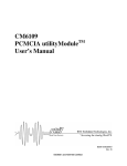
It should be noted that due to the power limitations with the Palm Pilot it is necessary to construct
a power adapter to power the ADC-16. A suggested design for the power adapter is:
LINUX
See the adc16.tar file for more information.
Serial port configurations
Serial drivers need to know two things about a serial port in order to operate the port correctly- its base address and its
interrupt number (IRQ).
Most PCs have two serial ports fitted, COM1 and COM2: all software works correctly when just these ports are fitted.
There is also de facto standard for two more serial ports- COM3 and COM4. The addresses of these ports are unique, but
the IRQ numbers are the same as for COM1 and COM2.
Port
Base address
Interrupt
Standard?
COM1
3F8
4
Yes
COM2
2F8
3
Yes
COM3
3E8
4
de facto
COM4
2E8
3
de facto
COM5...
No
Some serial port cards are capable of sharing an interrupt, and some software is capable of driving a serial port that is
sharing an interrupt, but it is likely that either hardware or software cannot handle interrupt sharing. If you install additional
COM ports as COM3 or COM4, using the default IRQs, these may interfere with devices connected to COM1 and COM2.
For example, an ADC-16 connected to COM3 may cause a mouse connected to COM1 not to function correclty.
The better quality serial port cards make it possible to use other interrrupts, for example IRQ5 or IRQ10. There are no
hard and fast rules about what IRQs are used by specific devices, so it is necessary to study the technical information
supplied with your computer and the proceed by trial and error. The following table of typical IRQ usages may be helpful.
IRQ0
55ms timer
IRQ1
Keyboard
IRQ2
Cascaded IRQ8..F
IRQ3
COM2
IRQ4
COM1
IRQ5
LPT2
IRQ6
Diskette
IRQ7
LPT1
IRQ8
Real time clock
IRQ9
Unavailable
IRQ10
general
IRQ11
general
IRQ12
general
IRQ13
Co-processor
IRQ14
Hard disk
IRQ15
general
If you wish to use non-standard IRQ values with Windows, you should find the following lines in C:\windows\system.ini,
and modify the details to the values that you have selected:
COM4Base=02E8
COM4Irq=3
COM3Base=03E8
COM3Irq=4
It is possible to buy multi-channel serial port cards (normally four or eight channels) where of the serial ports use the same
interrupt. There is not standards for these cards, so it is likely that DOS ADC-16 drivers will not work correctly. These
cards are normally supplied with Windows drivers, and so the ADC16 DLL should work correctly once the Windows
drivers for the serial card are installed.
Serial Connection
The information presented here is necessary only if you wish to write your own driver, or to connect the ADC-16 to
the PC in some unusual way (for example, via a radio modem).
The ADC-16 uses the following RS232 data lines (pin connections as on ADC-16)
Pin
Name Usage
3
TX Data from the PC to the ADC-16
2
RX Data from the ADC-16 to the PC
7
RTS Held at a positive voltage (>7V) to power the ADC-16
5
GND 0V line
4
DTR Held at a negative voltage (<-7V) to power the ADC-16
The driver powers up the ADC-16 by enabling RTS and disabling DTR to provide the correct polarity power
supply. If these are set incorrectly no damage will occur to either PC or ADC-16.
Serial Protocol
About a second after powering on the ADC-16, the driver can communicate with the ADC-16 as a normal RS232
device. The ADC-16 operates at 9600 baud with 1 stop bit and no parity.
The driver controls the ADC-16 using the following sequence
1.
2.
3.
4.
Switch RTS on and DTR off to provide power.
Wait for more than 1 second for the ADC-16 to settle
Send an single control byte to the ADC-16
Wait for the 3 byte response from the ADC-16
Steps 3 and 4 are repeated for each measurement.
The ADC-16 signals the end of conversion by sending three bytes. No data should be sent to the ADC-16 during
the conversion, as it may be lost or corrupted.
Control byte description
The control byte tells the ADC-16 the information it needs to carry out a conversion. It has the following format,
where bit 7 is the msb and bit 0 is the lsb:
Bits
Function
7-5
Set the channel 000 = channel 1
001 = channel 2
...........
110 = channel 7
111 = channel 8
Select
0111 = 8 bit
Resolution
1000 = 9 bit
..........
1110 = 15 bit
1111 = 16 bit
Mode
1 = single ended
0 = differential
4-1
0
Value
If the mode bit is 1, each channel voltage will be measured with respect to ground (single ended operation). If the
mode bit is 0 then adjacent channels act as differential pairs. Differential operation can be useful if problems due to
earth loops are encountered.
If you select channel 1 and differential operation, the ADC-16 will measure the voltage between channels 1 and 2.
Similarly selecting channel 3 will cause the voltage to be measured between channels 3 and 4. Whilst in differential
mode, selecting even channel numbers may give incorrect results.
The control byte 00000001 is a request for the version number: see below for details of the version response. The
following examples show complete control bytes and their effects:
Binary
Hex
Effect
000 1111 1
1F
channel 1, 16 bits, single ended
110 0111 0
CE
channels 7 and 8, 8 bits, differential mode.
000 0000 1
01
request version number
Response format
On receipt of a control byte containing a valid data request, the ADC-16 will start a conversion cycle. At the end of
this conversion, the ADC-16 will respond by sending three bytes. Note that three bytes are sent even for 8-bit
readings.
Byte Contents
Value
1
Sign
value >= 0: ASCII + (hex 2B)
value < =: ASCII - (hex 2D)
2
Result MSB
Binary
3
Result LSB
Binary
For example, the value +41349 (which is hex 85A1) would be sent as hex 2B, 85, A1.
On receipt of a control byte containing a valid version request, the ADC-16 will respond immediately with the
version details in the following format:
Byte Contents
Value
1
ADC type
16 (hex 10)
2
version
decimal version number
Conversion times
The ADC-16's conversion time is affected by both the resolution and the applied voltage. The figures listed below are
worst case for each resolution. If a severe overload is applied to the input of the ADC-16 it will shut itself down: no
further communication with the ADC-16 will be possible until approximately 1 second after the overload is removed.
Resolution (bits)
(ms)
8
9
10
11
12
13
14
15
16
Conversion Time
6.6
8.9
14
23
41
78
151
298
657
Modem operation
The ADC-16 is normally connected directly to the computer, but it is also possible to access the ADC-16 via a modem
using the Windows driver.
It is necessary to provide power to the ADC-16, either by instructing the modem to provide power or by connecting a
power supply directly to the ADC-16. See serial connections for information.
For some radio modems, there is a delay between sending text to the modem and its arrival at the other end, and a similar
delay for the response from the TC08. If, for example, the maximum possible delay is 150ms each way, 300ms total, the
following text should be added to Win.INI so that the driver waits longer for each response.
[ADC16]
Turnround=300