1
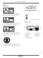
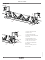
SVM 25E
SVM 25P
USER MANUAL IN ORIGINAL
Dok: 101501C-GB 1441
SVM 25E / SVM25P
CONTENTS
Dok: 101501C-GB 1441
SAFETY INSTRUCTIONS.................................... .... 3
OPERATION, PRECAUTIONS.................................. 3
TRANSPORT, PRECAUTIONS................................. 6
TECHNICAL DATA.................................................... 7
SIGNS....................................................................... .. 8
DESCRIPTION SVM25E........................................ .. 9
DESCRIPTION SVM25P......................................... .. 10
FIELD OF APPLICATION...................................... .. 11
ASSEMBLY OF MODULAR SECTIONS.............. .. 11
ASSEMBLY OF THE END PIECE AND
12
DRIVE UNIT............................................................ .. 13
ADJUSTMENT OF STRAIGHTNESS.................... .. 14
CROWN ON THE FLEX SCREED......................... .. 16
HONDA ENGINE....................................................... 16
START AND STOPPING THE ENGINE................... 17
FORWARD MOTION.............................................. .. 18
HANDLING THE WINSCHES.............................. ... 18
ACCESSORIES.......................................................... 21
CLEANING.............................................................. .. 22
MAINTENANCE..................................................... .. 23
DIMENSIONS........................................................... . 18; 19;20
LIFTING BY CRANE............................................... . 21
EC-DECLARATION OF CONFORMITY.................. 22
NOTES......................................................................... 23
SVM 25E / SVM25P
SAFETY INSTRUCTIONS
To reduce the risk of serious injury or death to yourself
or others read and understand the Safety and operating instruction before installing, operating, repairing,
maintaining, or changing accessories on the machine.
Post this Safety and operating instruction at work
locations, provide copies to employees, and make sure
that everyone reads the Safety and operating instruction
before operating or servicing the machine.
In addition, the operator or the operator’s employer
must assess the specific risks that maybe present as a
result of each use of the machine.
Additional instructionst for the engine can be found in
the manufacturer’s engine manual.
Personal precautions and qualifications
Only qualified and trained persons may operate or
maintain the machine.They must be physically able to
handle the bulk, weight, and power of the machine.
Always use your common sense and good judgement.
Personal protective equipment
Always use approved protective equipment.
Operators and all other persons in the working
area must wear protective equipment,i ncluding at a
minimum:
• Protective helmet
• Hearing protection
• Impact resistant eye protection with side protection
• Respiratory protection when appropriate
• Protective gloves
• Proper protective boots
• Appropriate work overall or similar clothing (not
loose-fitting) that covers your arms and legs.
Drugs, alcohol or medication
Drugs, alcohol or medication may impair your
judgment and powers of concentration. Poor reactions
and incorrect assessments can lead to severe accidents
or death.
Never use the machine when you are tired or under the
influence of drugs, alcohol or medication.
Dok: 101501C-GB 1441
No person who is under the influence of drugs,alcohol
or medication may operate the machine.
OPERATION, PRECAUTIONS
DANGER Explosion hazard
If a warm machine or exhaust pipe comes into
contact with explosives, an explosion couldoccur.
During operating with certain materials, sparks
and ignition can occur. Explosions will lead to
severe injuries or death.
Never operate the machine in any explosive
environment.
Never use the machine near flammable materials,
fumes or dust.
Make sure that there are no undetected sources of
gas or explosives.
Avoid contact with the warm exhaust pipe or
the bottom of the machine.
DANGER Fire hazard
If a fire starts in the machine, it can cause injury.
If possible use an ABE-class powder
extinguisher, other wise usea BE-type carbon
dioxide fire extinguisher.
DANGER Fuel hazard
The fuel is flammable and fuel fumes can explode
when ignited, causing serious injury or death.
Protect your skin from contac twith the fuel.
If fuel has penetratedtheskin,consult a qualified
health professional.
Never remove the filler cap,or fill the fueltank
when the machine is hot.
Fill thef ueltank outdoors or in aclean and well
ventilated place, free from sparks and open
flames. Fill the fuel tank at least ten meters (30
feet)from the place where the machine is to be
used.
Release the filler cap slowly to let pressure
escape.
Never over fill the fuel tank.
Make sure the filler cap is screwed on when the
machine is used.
Avoid spilling fuel on the machine, wipe off any
spilled fuel.
Check regularly for fuel leaks. Never use the
machine if it is leaking fuel.
Never use the machine in the proximity of
material that can generate sparks.Remove all hot
or spark-generating devices before startingthe
machine.
3
SVM 25E / SVM25P
Never smoke when filling the fuel tank or when
working with the machine or servicing it.
Only store fuel in a container that is specially
constructed and approved for the purpose.
If the machine has an exhaust, direct the exhaust
so as to reduce disturbance of dustin a dust filled
environment.
Consumed fuel and oil containers must be
taken care of and returned to the retailer.
Operate and maintain the machine as recommended
in the operating and safety instructions.
Never use your fingers to check for fluid leaks.
Wear washable or disposable protective clothes at the worksite, and shower and change in
to clean clothes before leaving the work site to
reduce exposure of dust and fumes to your self, other
persons, cars, homes, and other areas.
The machine is exposed to heavy strains during
operation.If the machine breaks or gets stuck,
there maybe sudden and unexpected movemen
that can cause injuries.
Always inspect the machine prior to use. Never
use the machine if you suspect that it is damaged.
Make sure that the handle is clean and free of
grease and oil.
Keep your feet away from the machine.
Never sit on the machine.
Never strike or abuse the machine.
Pay attention and look at what you are doing.
WARNING Dust and fume hazard
Dusts and /or fumes generated or dispersed when
using the machine may cause serious and permanent respiratory disease, illness, or other bodily
injury (forexample, silicosis or other irreversible
lung disease that can be fatal, cancer, birth defects,
and /or skin inflammation). Some dusts and fumes
created by compaction work contain substances
known to cause respiratory disease, cancer, birth
defects, or other reproductive harm.
Dust and fumes in the air can be invisible to
the naked eye, so do not rely on eye sight to
determine if there is dust or fumes are the air.
To reduce the risk of exposure to dust and fumes, do
all of the following:
Perform site-specific risk assessment. The risk
assessment should include dust and fumes created
by the use of the machine and the potential for
disturbing existing dust.
Wear, maintain and correctly use respiratory
protection as instructed by your employer and
as required by occupational health and safety
regulations. Ther espiratory protection must be
effective for the type of substance at issue (and
if applicable, approved by relevant governmental
authority).
Avoid eating,drinking, and using tobacco products in
areas where there is dust or fumes.
Wash your hands and face thoroughly as soon as
possible upon leaving the exposure area,and always
before eating, drinking, using tobacco products,or
making contact with other persons.
Comply with all applicable laws and regultions,
including occupational health and safety regulations.
Participate in air monitoring, medical examination
programs, and health and safety training programs
provided by your employer or trade organizations
and in accordance with occupational health and
safety regulations and recommendations. Consult
with physicians experienced in relevant occupational
medicine.
Work with your employer and trade organization
to reduce dust and fume exposure at the work site
and to reduce the risks. Effective health and safety
programs, policies and procedures for protecting
workers and others against harmful exposure to dust
and fumes should be established and mplemented
based on advice from health and safety experts.
Consult with experts.
DANGER Exhaust gas hazard
The exhaust gas from the machine’s combustion
engine contains carbon monoxide which is poisonous, and chemicals which cause cancer, birth
defects, or other reproductive harm. Inhalation of
exhaust fumes can cause serious injury, illness, or
death.
Never inhale exhaust fumes.
Ensure good ventilation (extraction of air by fan
if necessary).
Dok: 101501C-GB 1441
WARNING Unexpected movements
4
Work in a well ventilated area.
SVM 25E / SVM25P
WARNING Projectiles
Failure of the work piece, of accessories, or even
of the machine itself may generate high velocity
projectiles. During operating, splinters or other
particles from the compacted material may become
projectiles and cause personal injury by striking the
operator or other persons.To reduce these risk:
Use approved personal protective equipment and safety helmet, including impact resistant eye protection
with side protection.
Make sure that no unauthorised persons trespass into
the working zone.
Keep the work place free from foreign objects.
If numbness, persistent recurring discomfort,
burning sensation, stiffness, throbbing, tingling,
pain, clumsiness, weakened grip,whitening of the
skin, or other symptoms occurat any time, when
operating the machine or when not operating the
machine, stop operating the machine, tell your
employer and seek medical attention. Continued
use of the machine after the occurrence of any
such symptom may increase the risk of symptoms
becoming more severe and /or permanent.
Operate and maintain the machine as recommended in these instructions, to prevent an unnecessary
increase in vibration.
WARNING Rotating blades hazards
The following may help to reduce exposure to
vibration for the operator:
There is a risk of hands and feet getting caught by
the rotating blades when the machine is running.
This can cause personal injury.
If the machine has vibration absorbing handles, keep
them in a central position, avoid pressing the handles
into the end stops.
Never place your hands or feet inside the protection
ring when the machine is running
When the percussion mechanism is activated, the
only body contact with the machine yous hould have
are your hands on the handle or handles. Avoid any
other contact, for example supporting any part of
the body against the machine or leaning onto the
machine trying to increase the feed force.
WARNING Motions hazards
When using the machine to perform work-related
activities, you may experience discomfort in the
hands, arms, shoulders, neck, or other parts of the
body.
Adopt a comfortable posture whilst maintaining
secure footing and avoiding awkward off-balanced
postures.
Changing posture during extended tasks may help
avoid discomfort and fatigue.
In case of persistent or recurring symptoms, consult
a qualified health professional.
WARNING Vibrations hazards
Immediately stop working if the machine
suddenly starts to vibrate strongly. Before resuming
the work, find and remove the cause of the increased
vibrations.
Participate in health surveillance or monitoring,
medical exams and training programs offered by
your employer and when required by law.
When working in cold conditions wear warm
clothing and keep hands warm and dry.
See the”Noise and vibration declaration
statement”for the machine, including the declared
vibration values. This information can be found at
the end of these Safety and operating instructions.
Dok: 101501C-GB 1441
Normal and proper use of the machine exposes the
operator to vibration.Regular and frequent exposure
to vibration may cause, contribute to, or aggravate
injury or disorders to the operator’sf ingers, hands,
wrists, arms, shoulders and/or nerves and blood
supply or other bodyparts, including debilitating
and/or permanent injuries or disorders that may
develop gradually over periods of weeks, months, or
years.Such injuries or disorders may include damage
to the blood circulatory system, damage to the nervous system, damage to joints, and possibly damage
to other body structures.
Make sure that the machine is well-maintained and
not worn out.
5
SVM 25E / SVM25P
Never grab or touch a rotating machine part.
Avoid wearing clothing, neck ware or gloves
that may get caught.
Cover long hair with a hair net.
DANGER Electrical hazard
The machine is not electrically insulated. If the
machine comes in to contact with electricity, serious
injuries or death may result.
Never operate the machine near any electric wire or
other source of electricity.
Make sure that there are no concealed wires or other
sources of electricity in the working area.
DANGER Concealed object hazard
During operating, concealed wires and pipes
constitute a danger that can result in serious injury.
Check the composition of the material before
operating.
Watch out for concealed cables and pipes for
example electricity, telephone, water, gas, and
sewage lines.
If the machine seems to have hit a concealed object,
switch off the machine immediately.
Make sure that there is no danger before continuing.
WARNING Involuntary start
Involuntary start of the machine may cause injury.
Keep your hands away from the start and stop device
until you are ready to start the machine.
Learn how the machine is switched off in the event
of an emergency.
WARNING Noise hazard
High noise levels can cause permanent and
disablinghearing loss and other problems such as
tinnitus(ringing, buzzing, whistling, or humming in
the ears).To reduce risks and prevent an unnecessary
increase in noise levels:
Risk assessment of these hazards and implementation of appropriate controls is essential.
Operate and maintain the machine as recommended
in these instructions.
If the machine has as ilencer, check that it is in place
and in good working condition.
Always use hearing protection.
6
TRANSPORT, PRECAUTIONS
WARNING Loading and unloading hazard
When the machine is lifted by a crane and similar
appliance, this can lead to injury.
Use marked lifting points.
Make sure that all lifting devices are dimensionedfor
the weight of the machine.
Never remain under or in the immediate vicinity of
the machine.
MAINTENANCE, PRECAUTIONS
WARNING Unexpected start hazard
During maintenance or when changing blades on the
machine, there is a risk that the engine backfires or
that the machine unexpectedly starts. This applies
especially when the engine is hot and if the switch
is in position ON.This can result in serious personal
injury.
Always let the engine cool down.
Always turn the switch to position OFF.
Always take the cap off the spark plug.
WARNING Unexpected start hazard
Any machine modification may result in bodily
injuries to yourself or others.
Never modify the machine. Modified machines
are not covered by warranty or product liability.
Always use original parts, insertion tools, and
accessories.
Change damaged parts immediately.
Replace worn components in good time.
CAUTION High temperature
The machine’s engine exhaust pipe, and bottom
become hot during operation. Touching them can
lead to burns.
Never touch a hot machine.
Never touch the bottom of the machine when its hot.
Wait until the engine, exhaust pipe, and bottom of
the machine have cooled down before carrying out
maintenance work.
STORAGE, PRECAUTIONS
Keep the machine in a safe place, out of the reach
of children and locked up.
Dok: 101501C-GB 1441
WARNING Trapping hazards
There is a risk of neck ware, hair, gloves, and
clothes getting dragged into or caught by rotating
machineparts.This may cause choking, scalping,
lacerations, or death.To reduce the risk:
SVM 25E / SVM25P
TECHNICAL DATA
SVM 25E
Motor ...............................................................3-phase, 400 V
Over load protection....................................................1,2 amp
Sealing class ....................................................................IP 65
Engine output................................................................2.2 kW
Speed, (engine shaft) rpm.........................................2830 rpm
Centrifugal force .......................................................500 N/m
Weights
Weight el. drive unit incl. electrical winch set................61 kg
Weight end unit incl. manual winch ...............................25 kg
Weight module 3 m ..... ...................................................64 kg
Weight module 2 m ........................................................42 kg
Weight module 1 m.......... ...............................................26 kg
Weight module 0.75 m .......... .........................................24 kg
Weight module 0.50 m .......... .........................................22 kg
Dimensions
Max. length of modular screed......................................25 mm
Drive unit, L x W x H .................................300x400x950 mm
End section, L x W x H..................................50x400x950 mm
Modules, W x H ..................................................400x556 mm
Hand/arm vibrations HAV according to ISO 5349 on fresh
concrete ......................................................................4,5 m/s2
Guaranteed sound-power level, LWA........................106 dB(A)
Sound pressure level (at operators ear).....................95 dB(A)
SVM 25P
Engine, petrol................................................................GX200
Engine, output................................................................4,1kW
Speed, (engine shaft) rpm.........................................3600 rpm
Centrifugal force ........................................................500 N/m
Dok: 101501C-GB 1441
Weights
Weight el. drive unit incl. electrical winch set.................61 kg
Weight end unit incl. manual winch ...............................25 kg
Weight module 3 m ..... ...................................................64 kg
Weight module 2 m ........................................................42 kg
Weight module 1 m.......... ...............................................26 kg
Weight module 0.75 m .......... .........................................24 kg
Weight module 0.50 m .......... .........................................22 kg
Dimensions
Max. length of modular screed.......................................25 mm
Drive unit, L x W x H .................................300x400x950 mm
End section, L x W x H..................................50x400x950 mm
Modules, W x H ..................................................400x556 mm
Hand/arm vibrations HAV according to ISO 5349 on fresh
concrete ......................................................................4,5 m/s2
Guaranteed sound-power level, LWA........................106 dB(A)
Sound pressure level (at operators ear).....................95 dB(A)
7
SVM 25E / SVM25P
SIGNS
Warning Signs
The sticker shows the electrical system voltage supply.
Before use, carefully read the manual and its safety
instructions so that you can handle the machine safely.
Ensure that the manual is always accessible.
NOTE! Use only the machine´s lifting eye to lift the
machine.
Machine Signs
1
Engine and silencer: to avoid burns or discomfort, do
not touch hot engine parts when the engine is on or
when the machine has recently been used.
2
3
9
8
4
MACHINERY
5
7
Belt drive: Keep hands, tools and other objects away
from the belt drive when the machine is on to avoid
injury and damage. See the safety instructions in the
manual.
1. Manufacturer
2. Place, country of
manufacture.
3. CE mark.
4. Model name.
5. Year of manufacture.
6
6.
7.
8.
9.
Max. engine power.
Max. weight.
Serial number.
Machine type
Dok: 101501C-GB 1441
As the sound pressure level at the operator’s ears
exceeds 80 dB (A), ear protectors must be used when
working with the machine to prevent hearing damage.
8
SVM 25E / SVM25P
DESCRIPTION
SVM 25E
5
1
2
3
4
1; End piece with manual winch
6
2; Modular section
3; Connector male and female
7
4; Electrice drive unit with manual winch
8
5; Turnbuckle
6; Devibrated holder for winch
7; Hand winch including 30 m wire
9
10
11
13
8; Main switch and appliance inlet (include
over load protection)
9; Lifting device (for operator)
10; V-belt and cover (cogged V-belt)
12
11; Wire block
12; Holes for attaching accessories
Dok: 101501C-GB 1441
13; Electric motor and motor cover
9
SVM 25E / SVM25P
DESCRIPTION
SVM 25P
5
1
2
3
6
4
1; End piece with manual winch
2; Modular section
7
3; Connector male and female
4; Petrol drive unit with manual winch
5; Turnbuckle
6; Devibrated holder for winch
8
9
7; Hand winch including 30 m wire
8; Lifting device (for operator)
10
9; V-belt and cover (poly V-belt)
10; Wire block
12
11; Holes for attaching accessories
12; Petrol engine
Dok: 101501C-GB 1441
11
10
SVM 25E / SVM25P
FIELD OF APPLICATION
The Swepac SVM 25 is a modular screeed used for levelling horizontal concrete surfaces after casting. The machine
is pulled on screed rails by means of manual winches or Swepac electric winches.
The Swepac SVM 25 can also be run on Swepac track rails if there is a rigid reinforcement or other steady base
available.
Important! There must not be any big overhangs when placing track rails or screed rails. The
modular screed is designed for compressive forces on the upper, circular tube of the screed.
Two men ar needed to operate the machine. The one handling the start/stop as well as one manual switch. This
operator walks on the drive unit side. The other operator guides the winch on teh opposite side.
ASSEMBLY OF MODULAR SECTIONS
See the illustration below.
Place the modular sections on a level base, and always use short edge boards as trestles in order to get the sections as
straight as possible at assembly.
A Unscrew the dorned nuts (1) from the screws (2).
B Check that the arrow markings (3) on the protective covers (4) have the same direction.
C Fasten the rubber cross (5) on one of the couplings.
D Press the sections together.
E Tighten the hat nuts (1)
F Screw on the turnbuckle (6) so that the hole in the link screw (7) comes to the middle of thehole inte the fork (8)
and assemble the bolt (9) and lock it withthe cotter key (10).
G See Chapter ADJUSTMENT OF STRAIGHTNESS and CROWN ON THE FLEX SCREED
8
9
7
10
6
Dok: 101501C-GB 1441
4
3
3
4
1
6
2
11
SVM 25E / SVM25P
ASSEMBLY OF THE END PIECE AND DRIVE
UNIT
• The end piece is assembled in the same way as the modules according to points A,D and E above.
• The drive unit is assembled in the same way as the modules according to points A up to E.
• Assembly the turnbuckle system according the illustration on the previous page.
• Check that the end piece and the drive unit are in an right angle towards the screed and lock it with the nuts.
See illustration below to the right
DRIVE UNIT
Turnbuckle
Dok: 101501C-GB 1441
Turnbuckle
END UNIT
12
SVM 25E / SVM25P
ADJUSTMENT OF STRAIGHTNESS
A. Place a trestle or other support at each end of the assembled machine so that the bottom edge is free.
Tension a string along the bottom edge of the screed.
B. Unscrew the locking nuts (1) and adjust the tensioning at each jointing with the turnbuckle (2) till the
entire screed is straight according to the string.
C. Lock the turnbuckles with the locking nuts (1) so that the tensioning will not change when the screed is
in operation.
D. Check the straightness
See the illustration below.
CROWN ON THE FLEX SCREED
The SVM 25 can be given a crown of ± 5 % at each joint. Exceptionally, a crown of ± 7% may be achieved but
this would shorten the life of the shaft coupling.
In order to get a crown at a joint, proceed as follows:
A- E Assemble the modular sections according to A-F under the heading ”Assembly of modular sections”
F. Unscrew the nuts (4 pcs) on the inside (3) about one turn.
Important! If the screed has been in action earlier check that there is no concrete incrustation in the
thread of the screws (3).
G. Adjust to proper crown with the turnbuckle (2).
H. Tighten the four nuts (3).
I. Lock the turnbuckle (2) with the locking nut (1). 3
Dok: 101501C-GB 1441
See the illustration below.
1
2
3
13
SVM 25E / SVM25P
Honda engine
8
Regular Check
6
7
5
The air filter must be checked at least once every
working week. When working in dusty conditions,
check daily.
1
1
2
1. Paper element
2. Foam plastic element
2
3
4
9
1; Spark plug
2; Engine valves
3; Engine oil/dipstick
4; Carburettor
5; Silencer
6; Fuel filler cap
7; Fuel tank
8; Air filter
9; Recoil starter
Fuel Check
Check that there is fuel in the tank. Fill up if necessary.
Engine Oil Level Check
Check the oil level in the crankcase every day. The
oil must reach the edge of the filling hole when the
machine is on a level surface.
1.Remove the foam plastic element and the
paper element and check that they are undamaged.
Replace damaged parts.
2. Wash the foam plastic element in liquid with a high
flashpoint and let it dry properly. Dip in engine oil
and squeeze dry.
3. Strike the paper element against a hard object a few
times to loosen any dirt.
V-belt Drive
Check the tension and condition of the V-belt regularly.
Replace a damaged V-belt with the new type according
to the table below
Machine type
V-belt type
SVM 25E
Optibelt Omega 565 5M
SVM 25P
Poly V-rem 11PJ559
Check every day that the engine is not leaking oil or fuel. If a leak
is discovered, the machine may not be operated until the fault has
been remedied.
14
Dok: 101501C-GB 1441
Oil/Fuel Leakage
SVM 25E / SVM25P
START
spac103
Off
Engine power switch
On
Fuel cock
Open the choke gradually.
Run an cold engine warm for max 5 minutes depending
on the air-and engine temperature.
STOPPING the engine
Switch the engine to idle and let it run for a few
minutes.
Switch the engine power switch to “0”.
Close the fuel cock.
Closed Open
Choke
See Daily Checks on page 10.
STARTING the engine
Switch the engine power switch to “1”.
Open the fuel cock.
If neccessary, lift the dead man´s grip and switch the
throttle lever to min. position (idle speed).
Adjust the choke. If the engine is cold, close the choke
completely. Do not use the choke if the engine is warm
or if the air temperature is high.
Start by pulling the starting handle. Pull it first until the
Dok: 101501C-GB 1441
mechanism engages. Then pull it hard and fast.
15
SVM 25E / SVM25P
FORWARD MOTION
The SVM25 screed is as standard equipped with two manual winches. (1), steel cable (2) and eye bolt hook (3).
But it can also be equipped with electric winches, as an option or factory mounted. In case this is an option, it´s
described in a separate assemble instruction.
The cable is pulled through the pulley-block(4) and fastened at the remote end of the cas-ting bay. Check that
the cable is in an right angle towards the beam. If the cable runs obli-quely it may get the screed draw laterally.
Keep the cable tensioned and without kinks. In this way it will function better and get a longer life. Check now
and then that the cable is evenly coiled around the drum. An irregular winding causes unne-cessary wear on the
cable and would f ll the drum too quickly.
See the illustration below.
1
2
3
4
HANDLING OF THE WINSCHES
Manualwinches:
In order to let the cable run freely, the manual winches can be disengaged in the following way:
A. Turn the crank (1) backwards 2 turns without load.
B. Remove the crank and fasten it on the fastening device (2).
C. Unwind the cable.
D. Put the crank back and crank the cable.
2
Dok: 101501C-GB 1441
1
16
SVM 25E / SVM25P
Electric winches:
A. If the cable is tense in its position, remove the pressure on the cable by turning the electric knob on electric
box to the other direction (turning the phase direction)
B. Pull out the knob with the pin placed on the cable drum (1) and locks it on the outer position (2)
C. Unwind the cable
D. Start the electric winches by turning the knob to the intended direction
1
2
Warning! Both the manual and electric winches. are intended for horizontal pulling. They do not meet safety
requirements for vertical lifting tackles.It is very dangerous to have load hanging on the manual winches as they
do not have a safe function for lowering weights.
For lengths exceeding 16 m it is advisable to use a third winch placed on the end piece. The cable is drawn via
three pulley-blocks to a fixing point centrally placed in the casting bay.
ACCESSORIES
Swepac offer a number of options which are available for the screed. They are as following:
ARTICLE NUMBER
DESCRIPTION
Kit part number 601209
Electric winches.
Kit part number 601154
and 601160
Kit part number 601144
Outrigger U2 and U3. To be used on prepared rails.
Dok: 101501C-GB 1441
Coupling for high slopes. To be used whenever the standard angles not are
enough.
17
SVM 25E / SVM25P
CLEANING
All surfaces except the T-prof les are powder-lacquered or galvanized in order to facilitate cleaning. In order
to further simplify the cleaning, the screed may be sprayed with silicone oil or form oil before casting.
The Swepac SVM 25 may be flushed with a high pressure washer but then the engine has to be covered so
that no water comes on the carburettor, fuel tank or generator. Also clean the shaft but avoid f ushing the
bearings. Tilt it so the underside can be cleaned. Note! Petrol engine can only be tilted at one direction!
It is important to clean the machine carefully after each operation in order to ensure a long-lasting and safe
function.
MAINTENANCE
The bearings are permanently lubricated and need not be after-greased.Check before each assembly that the
rubber crosses in the shaft couplings are without damage. Replace, if necessary.
WARNING!
NOT ALLOVED
OK
C
B
DIMENSIONS
A
18
E
Dok: 101501C-GB 1441
D
Dok: 101501C-GB 1441
L
K
H
F
SVM 25E / SVM25P
G
I
J
M
19
SVM 25E / SVM25P
N*
Position Low profile
A
B
C
D
E
F
G
H
I
J
K
L
M
354mm
805mm
754mm
414mm
700mm
805mm
354mm
415mm
148mm
217mm
804mm
513mm
354mm
Article number
Position
Lenght of the modular sections
601223
601224
601225
601226
601227
N*
N*
N*
N*
N*
0.50m
0.75m
1m
2m
3m
Article number
Position
Description
601280
601372
O*
P*
Electric drive unit 0,3m low with manual winch
End piece low with manual winch
O*
Dok: 101501C-GB 1441
P*
20
SVM 25E / SVM25P
LIFTING BY CRANE
At greater lenghts (>10 m) it is important to use lifting straps. The strap ends are fixed at a distance of about
1/3 of the screed length from each other.
Warning! The screed may get deformed, if it is raised in the middle only.
Dok: 101501C-GB 1441
See the illustration below.
21
SVM 25E / SVM25P
EC-declaration of conformity
Manufacturer
Swepac AB
Blockvägen 3
34132 Ljungby
1. Category: Surface Vibrator
2. Type: SVM 25E
SVM 25P
3. Engine output.:
SVM 25E.......................2,2kW
SVM 25P........................4,1kW
The product complies with the following directives:
2006 / 42 / EG
2000 / 14 /EG
2004 / 108 / EG
EN 500-1
EN 500-4
EN 12649:2008+A1:2011
ISO 11201
ISO 5349-2:2001
Swepac AB, Blockvägen 3 SE-34132 Ljungby
Hans Holmlund / Product Manager
22
Dok: 101501C-GB 1441
Technical documentation held by:
SVM 25E / SVM25P
Dok: 101501C-GB 1441
NOTES
23
SWEPAC AB
Address Blockvägen 3, 341 32 Ljungby, Sweden, tel. +46 (0)372-156 00, fax +46 (0)372-837 41, E-mail [email protected],
Internet www.swepac.se