1
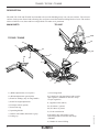
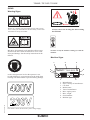
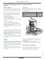
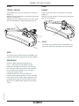
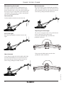
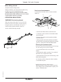
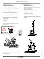
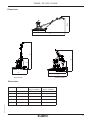
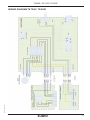
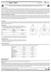
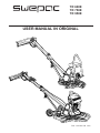
TR 600E
TR 750E
TR 950E
USER MANUAL IN ORIGINAL
Dok: 101506A-GB 1442
TR600E / TR 750E / TR 950E
CONTENTS
Dok: 101506A-GB 1442
SAFETY INSTRUCTIONS...................................... 3
OPERATION, PRECAUTIONS...................3, 4, 5, 6
TRANSPORT, PRECAUTIONS.............................. 6
MAINTENANCE, PRECAUTIONS........................ 6
TECHNICAL DATA................................................. 7
DESCRIPTION........................................................ 8
SIGNS....................................................................... 9
DESCRIPTION MOTOR AND ELECTRIC
SYSTEM.................................................................10
REGULAR CHECKS............................................. 10
START AND STOPP.............................................. 11
OPERATING.............................................. 11; 12; 13
LIFTING AND TRANSPORTATION....................14
DIMENSION...........................................................15
TROUBLESHOOTING TR750E / TR950E..... 16; 18
WIRING DIAGRAM TR750E / TR950E...............17
STORAGE AND DISPOSAL................................. 19
NOTES..................................................19; 20; 21; 22
EC-DECLARATION OF CONFORMITY..............23
2
TR600E / TR 750E / TR 950E
SAFETY INSTRUCTIONS
To reduce the risk of serious injury or death to yourself
or others read and understand the Safety and operating instruction before installing, operating, repairing,
maintaining, or changing accessories on the machine.
Post this Safety and operating instruction at work
locations, provide copies to employees, and make sure
that everyone reads the Safety and operating instruction
before operating or servicing the machine.
In addition, the operator or the operator’s employer
must assess the specific risks that maybe present as a
result of each use of the machine.
Additional instructionst for the engine can be found in
the manufacturer’s engine manual.
Personal precautions and qualifications
Only qualified and trained persons may operate or
maintain the machine.They must be physically able to
handle the bulk, weight, and power of the machine.
Always use your common sense and good judgement.
Personal protective equipment
Always use approved protective equipment.
Operators and all other persons in the working
area must wear protective equipment, including at a
minimum:
• Protective helmet
• Hearing protection
• Impact resistant eye protection with side protection
• Respiratory protection when appropriate
• Protective gloves
• Proper protective boots
• Appropriate work overall or similar clothing (not
loose-fitting) that covers your arms and legs.
Drugs, alcohol or medication
Drugs, alcohol or medication may impair your
judgment and powers of concentration. Poor reactions
and incorrect assessments can lead to severe accidents
or death.
Dok: 101506A-GB 1442
Never use the machine when you are tired or under the
influence of drugs, alcohol or medication.
OPERATION, PRECAUTIONS
DANGER Explosion hazard
If a warm machine or exhaust pipe comes into
contact with explosives, an explosion could occur.
During operating with certain materials, sparks
and ignition can occur. Explosions will lead to
severe injuries or death.
Never operate the machine in any explosive
environment.
Never use the machine near flammable materials,
fumes or dust.
Make sure that there are no undetected sources of
gas or explosives.
Avoid contact with the warm exhaust pipe or
the bottom of the machine.
DANGER Fire hazard
If a fire starts in the machine, it can cause injury.
If possible use an ABE-class powder
extinguisher, otherwise use a BE-type carbon
dioxide fire extinguisher.
DANGER Fuel hazard
The fuel is flammable and fuel fumes can explode
when ignited, causing serious injury or death.
Protect your skin from contact with the fuel.If
fuel has penetrated the skin,consult a qualified
health professional.
Never remove the filler cap, or fill the fueltank
when the machine is hot.
Fill the fueltank outdoors or in a clean and well
ventilated place, free from sparks and open
flames. Fill the fuel tank at least ten meters (30
feet)from the place where the machine is to be
used.
Release the filler cap slowly to let pressure
escape.
Never over fill the fuel tank.
Make sure the filler cap is screwed on when the
machine is used.
Avoid spilling fuel on the machine, wipe off any
spilled fuel.
Check regularly for fuel leaks. Never use the
machine if it is leaking fuel.
Never use the machine in the proximity of
material that can generate sparks.Remove all hot
or spark-generating devices before starting the
machine.
3
TR600E / TR 750E / TR 950E
Only store fuel in a container that is specially
constructed and approved for the purpose.
Consumed fuel and oil containers must be
taken care of and returned to the retailer.
Never use your fingers to check for fluid leaks.
WARNING Unexpected movements
The machine is exposed to heavy strains during
operation.If the machine breaks or gets stuck,
there may be sudden and unexpected movement
that can cause injuries.
Always inspect the machine prior to use. Never
use the machine if you suspect that it is damaged.
Make sure that the handle is clean and free of
grease and oil.
Keep your feet away from the machine.
Never sit on the machine.
Never strike or abuse the machine.
Pay attention and look at what you are doing.
WARNING Dust and fume hazard
Dusts and /or fumes generated or dispersed when
using the machine may cause serious and permanent respiratory disease, illness, or other bodily
injury. Some dusts and fumes created by compaction work contain substances known to cause respiratory disease, cancer, birth defects, or other
reproductive harm.
Dust and fumes in the air can be invisible to
the naked eye, so do not rely on eye sight to
determine if there is dust or fumes are the air.
To reduce the risk of exposure to dust and fumes, do
all of the following:
Perform site-specific risk assessment. The risk
assessment should include dust and fumes created
by the use of the machine and the potential for
disturbing existing dust.
Wear, maintain and correctly use respiratory
protection as instructed by your employer and
as required by occupational health and safety
regulations. The respiratory protection must be
effective for the type of substance at issue (and
if applicable, approved by relevant governmental
authority).
4
Work in a well ventilated area.
If the machine has an exhaust, direct the exhaust
so as to reduce disturbance of dust in a dust filled
environment.
Operate and maintain the machine as recommended
in the operating and safety instructions.
Wear washable or disposable protective clothes at the worksite, and shower and change in
to clean clothes before leaving the work site to
reduce exposure of dust and fumes to your self, other
persons, cars, homes, and other areas.
Avoid eating,drinking, and using tobacco products in
areas where there is dust or fumes.
Wash your hands and face thoroughly as soon as
possible upon leaving the exposure area,and always
before eating, drinking, using tobacco products,or
making contact with other persons.
Comply with all applicable laws and regultions,
including occupational health and safety regulations.
Participate in air monitoring, medical examination
programs, and health and safety training programs
provided by your employer or trade organizations
and in accordance with occupational health and
safety regulations and recommendations. Consult
with physicians experienced in relevant occupational
medicine.
Work with your employer and trade organization
to reduce dust and fume exposure at the work site
and to reduce the risks. Effective health and safety
programs, policies and procedures for protecting
workers and others against harmful exposure to dust
and fumes should be established and implemented
based on advice from health and safety experts.
Consult with experts.
DANGER Exhaust gas hazard
The exhaust gas from the machine’s combustion
engine contains carbon monoxide which is poisonous, and chemicals which cause cancer, birth
defects, or other reproductive harm. Inhalation of
exhaust fumes can cause serious injury, illness, or
death.
Never inhale exhaust fumes.
Ensure good ventilation (extraction of air by fan
if necessary).
Dok: 101506A-GB 1442
Never smoke when filling the fuel tank or when
working with the machine or servicing it.
TR600E / TR 750E / TR 950E
WARNING Projectiles
Failure of the work piece, of accessories, or even
of the machine itself may generate high velocity
projectiles. During operating, splinters or other
particles from the compacted material may become
projectiles and cause personal injury by striking the
operator or other persons.To reduce these risk:
Use approved personal protective equipment and safety helmet, including impact resistant eye protection
with side protection.
Make sure that no unauthorized persons trespass into
the working zone.
Keep the work place free from foreign objects.
WARNING Rotating blades hazards
There is a risk of hands and feet getting caught by
the rotating blades when the machine is running.
This can cause personal injury.
Never place your hands or feet inside the protection
ring when the machine is running
WARNING Motions hazards
Operate and maintain the machine as recommended in these instructions, to prevent an unnecessary
increase in vibration.
The following may help to reduce exposure to
vibration for the operator:
Make sure that the machine is well-maintained and
not worn out.
Immediately stop working if the machine
suddenly starts to vibrate strongly. Before resuming
the work, find and remove the cause of the increased
vibrations.
Participate in health surveillance or monitoring,
medical exams and training programs offered by
your employer and when required by law.
When working in cold conditions wear warm
clothing and keep hands warm and dry.
See the”Noise and vibration declaration
statement”for the machine, including the declared
vibration values. This information can be found on
the page 9.
When using the machine to perform work-related
activities, you may experience discomfort in the
hands, arms, shoulders, neck, or other parts of the
body.
Adopt a comfortable posture whilst maintaining
secure footing and avoiding awkward off-balanced
postures.
Changing posture during extended tasks may help
avoid discomfort and fatigue.
In case of persistent or recurring symptoms, consult
a qualified health professional.
WARNING Vibrations hazards
Dok: 101506A-GB 1442
Normal and proper use of the machine exposes the
operator to vibration.Regular and frequent exposure
to vibration may cause, contribute to, or aggravate
injury or disorders to the operator’sf ingers, hands,
wrists, arms, shoulders and/or nerves and blood
supply or other bodyparts, including debilitating
and/or permanent injuries or disorders that may
develop gradually over periods of weeks, months, or
years.Such injuries or disorders may include damage
to the blood circulatory system, damage to the nervous system, damage to joints, and possibly damage
to other body structures.
5
TR600E / TR 750E / TR 950E
Never grab or touch a rotating machine part.
Avoid wearing clothing, neck ware or gloves
that may get caught.
Cover long hair with a hair net.
DANGER Electrical hazard
The machine is not electrically insulated. If the
machine comes in to contact with electricity, serious
injuries or death may result.
Never operate the machine near any electric wire or
other source of electricity.
Make sure that there are no concealed wires or other
sources of electricity in the working area.
DANGER Concealed object hazard
During operating, concealed wires and pipes
constitute a danger that can result in serious injury.
Check the composition of the material before
operating.
Watch out for concealed cables and pipes for
example electricity, telephone, water, gas, and
sewage lines.
If the machine seems to have hit a concealed object,
switch off the machine immediately.
TRANSPORT, PRECAUTIONS
WARNING Loading and unloading hazard
When the machine is lifted by a crane and similar
appliance, this can lead to injury.
Use marked lifting points.
Make sure that all lifting devices are dimensioned
for the weight of the machine.
Never remain under or in the immediate vicinity of
the machine.
MAINTENANCE, PRECAUTIONS
WARNING Unexpected start hazard
During maintenance or when changing blades on the
machine, there is a risk that the engine backfires or
that the machine unexpectedly starts. This applies
especially when the engine is hot and if the engine
power switch is in position ON.This can result in
serious personal injury.
Always let the engine cool down.
Always turn the engine power switch to position
OFF.
Always take the cap off the spark plug.
WARNING Unexpected start hazard
Any machine modification may result in bodily
injuries to yourself or others.
Never modify the machine. Modified machines
are not covered by warranty or product liability.
Make sure that there is no danger before continuing.
Always use original parts, insertion tools, and
accessories.
WARNING Involuntary start
Involuntary start of the machine may cause injury.
Change damaged parts immediately.
Keep your hands away from the start and stop device
until you are ready to start the machine.
Learn how the machine is switched off in the event
of an emergency.
WARNING Noise hazard
High noise levels can cause permanent and
disablinghearing loss and other problems such as
tinnitus(ringing, buzzing, whistling, or humming in
the ears).To reduce risks and prevent an unnecessary
increase in noise levels:
Risk assessment of these hazards and implementation of appropriate controls is essential.
Operate and maintain the machine as recommended
in these instructions.
If the machine has a silencer, check that it is in place
and in good working condition.
Always use hearing protection.
6
Replace worn components in good time.
CAUTION High temperature
The machine’s engine exhaust pipe, and bottom
become hot during operation. Touching them can
lead to burns.
Never touch a hot machine.
Never touch the bottom of the machine when its hot.
Wait until the engine, exhaust pipe, and bottom of
the machine have cooled down before carrying out
maintenance work.
STORAGE, PRECAUTIONS
Keep the machine in a safe place, out of the reach
of children and locked up.
Dok: 101506A-GB 1442
WARNING Trapping hazards
There is a risk of neck ware, hair, gloves, and
clothes getting dragged into or caught by rotating
machineparts.This may cause choking, scalping,
lacerations, or death.To reduce the risk:
TR600E / TR 750E / TR 950E
TECHNICAL DATA
To reduce the risk of serious injury or death to your self or others, read the Safety instructions
section found on the previous pages of this manual before operating the machine.
TR 600E
Motor Power......................................................1,5 kW
Motor Type....................................230V, 1-phase 50 Hz
Speed, (motor shaft).......................................2810 rpm
Speed, (output shaft) ................................. ......130rpm
Net weight, TR 600E..........................................82,8kg
Weight transport wheels.......................................2,6kg
Dimensions
Diameter protecting ring...................................600 mm
Working diameter ,blades.................................581 mm
Outer diameter, disc........................................1740 mm
Length, working position.................................1640 mm
Height, working position...................................980 mm
Height transportation ................................ .......870 mm
Hand/arm vibrations hav according to ISO 5349
on fresh concrete working as a leveling disc....1,4 m/s2
Guaranteed sound-power level, LWA................93 dB(A)
Sound pressure level (at operators ear)...........70 dB(A)
TR 950E
TR 750E
Motor Power.....................................................2,5 kW
Motor Type............................................400V, 3-phase
Speed, (motor shaft)..............................850-2840 rpm
Speed, (output shaft) ................................. 40-133rpm
Inventer drive Power..........................................2.5kW
Inventer drive, Type...........................E84DGFCSNNP
Inventer drive, specifikation.........................1/0 modul
Motor and Inventer drive:
Form of production.................................................IP65
Net weight, TR750E............................................82,8kg
Dimensions
Diameter protecting ring..................................750 mm
Working diameter.............................................728 mm
Length working position, short handle..........1740 mm
Length working position, long handle...........1778 mm
Hand/arm vibrations hav according to ISO 5349
on fresh concrete working as a leveling disc...1,9 m/s2
Guaranteed sound-power level, LWA...............96 dB(A)
Sound pressure level (at operators ear)..........72 dB(A)
Motor Power.....................................................2,5 kW
Motor Type............................................400V, 3-phase
Speed, (motor shaft)..............................850-2840 rpm
Speed, (output shaft) ................................. 40-133rpm
Inventer drive Power..........................................2.5kW
Inventer drive, Type...........................E84DGFCSNNP
Inventer drive, specifikation.........................1/0 modul
Motor and Inventer drive:
Form of production.................................................IP65
Net weight, TR950E...........................................83,8kg
Dimensions
Diameter protecting ring..................................950 mm
Working diameter.............................................935 mm
Length working position, short handle..........1976 mm
Length working position, long handle...........2325 mm
Hand/arm vibrations hav according to ISO 5349
on fresh concrete working as a leveling disc...1,3 m/s2
Guaranteed sound-power level, LWA...............99 dB(A)
Sound pressure level (at operators ear)...........72 dB(A)
Denomination
Dok: 101506A-GB 1442
Article number
701120
Lubricants
TR600E / TR 750E / TR 950E
Leveling disc 750 mm
701226
Shell Regina Grease 2 or equivalent
Leveling disc 950 mm
701003
Grease, shaft for
blade adjustments
Gearbox oil
Synthetic Mobil SHC 634
Leveling disc 600 mm
7
TR600E / TR 750E / TR 950E
DESCRIPTION
TR 600E; TR 750E and TR 950E are intended to be used for finishing newly cast concrete surfaces. The concrete
surface can be power floated with a floating disc and power trowelled with trowelling blades of steel. The surface
achieved will be even, dense and have a high finish. No other use is permitted.
TR 600E
MAIN PARTS
12b
TR750E / TR950E
15
1a
6
11
14
7
1b
8
2
10
3
12a
4
5
1b; Blade adjustments (quick pitch)
2; Knob for folding (only for long handle)
3; Knob for height adjustment
4; Transport wheel (option)
5; Protection ring
6; Operating handle
7; Hold-to-run handle (Dead man’s grip)
8; Lifting eye
9; Troweling blade
10; Control box with start button and steeples
rpm-regulator. (TR600E do not have steeples rpm-regulator)
11; Appliance inlet (400V)
12a; El. Motor (3-phase)
12b; El. Motor (1-phase)
13; V-belt transmission
14; Rotating ring with rubber O-ring.
Protecting walls from marks and scraps.
(TR600E)
15; Handle for manual lifting
8
13
Dok: 101506A-GB 1442
1a; Blade adjustments (screw pitch)
9
TR600E / TR 750E / TR 950E
SIGNS
Warning Signs
Before use, carefully read the manual and its safety instructions so that you can handle the machine safely. Ensure that
the manual is always accessible.
Belt drive: Keep hands, tools and other objects away
from the belt drive when the machine is on to avoid
injury and damage. See the safety instructions in the
manual.
Always remove the leveling disc before lifting
the machine!
NOTE! Use only the machine´s lifting eye to lift the
machine.
Machine Signs
1
2
3
9
8
As the sound pressure level at the operator’s ears
exceeds 80 dB (A), ear protectors must be used when
working with the machine to prevent hearing damage.
4
MACHINERY
5
7
Dok: 101506A-GB 1442
1.
2.
3.
4.
5.
6.
7.
8.
9.
6
Manufacturer
Place, country of manufacture.
CE mark.
Model name.
Year of manufacture.
Max. engine power.
Max. weight.
Serial number.
Machine type
The stickers shows the electrical system voltage supply.
9
TR600E / TR 750E / TR 950E
DESCRIPTIONS MOTOR AND ELECTRIC
SYSTEM
REGULARY CHECKS
TR750E / TR950E
V-belt Drive
The trowel is powered by a 3-phase 400 V. electric
motor, which are driven by an efficiently inverter
drive. The motor has an inbuilt thermo protection.
Since the placement of the inverter is above the
electric motor and in the same time integrated, the
communication in-between they become simple,
covered and reliable.
The Inverter is equipped with:
- A large led status display- clearly visible, even under
the most challenging conditions.
- A vector steering. It means that it is very strong on
low rpm.
- Acceleration 3 seconds
- Inbuilt overload protection for over amps.
- An easy access of a connection for instrument to
measure the status and condition of the inverter. The
test instrument is an accessory.
- In case of wrong phase flow, the inverter will adjust
it automatically.
- The control box in the maneuver handle are placed
close, and in front of the operator for easily use and
reachability. It includes both the start button and the
steeples speed control. There is a magnetic switch
inside the box that stops the motor instantly when the
dead man´s grip is released.
- The cables are mounted inside the handle tubes to
protect them well, and without access to mechanical
wear and abuse.
Check the tension and condition of the V-belt regularly.
Replace a damaged V-belt with the new type according
to the table below
Machine type
TR 600E
TR 750E
V-belt type
XPA 782
XPA 707
TR 950E
XPA 707
2
1
Adjust the tensioning of the V-belt with the screw (pos 1)
Loosen the upper nut and look it carefully after the
adjusting (pos 2)
The trowel is powered by a 1-phase 230 electric motor.
See that the tensioning is proper without too much
- The control box in the maneuver handle are placed
tensioning which could harm the bearings in a long run.
close, and in front of the operator for easily use and
reachability. There is a magnetic switch inside the box
that stops the motor instantly when the dead man´s
Electric cables and Equipment
grip is released.
- The cables are mounted inside the handle tubes to
Check regularly the cables due to damages or cracks.
protect them well, and without access to mechanical
Check also visually conditions on other electric
wear and abuse.
equipment’s to prevent risk for any future failure.
Dok: 101506A-GB 1442
TR 600E
10
TR600E / TR 750E / TR 950E
START
START
TR750E / TR950E
TR600E
Lift the dead man’s grip (1) up against the operating
handle (2).
Hold the trowel prepared for an operating position and
push the start button (3).
Adjust the rpm by turning the knob to the left or right
direction depending on required operating rpm (4)
Lift the dead man’s grip (1) up against the operating
handle (2).
Hold the trowel prepared for an operating position and
push the start button (3).
4
2
3
3
2
1
STOP
1
To stop the motor and the rotation of the blades, just
release the dead man’s grip and it will stop instantly.
STOP
To stop the motor and the rotation of the blades, just
release the dead man’s grip and it will stop instantly.
OPERATING
NOTICE When using the floating disc, be
aware of the position of the blades. All four
blades must be inside the brackets on the floating
disc. Also check the centre position of the floating
disc in relation to the blade cross, to avoid any
eccentricity during rotation.
Dok: 101506A-GB 1442
NOTICE Observe the concrete surface for
loosened stones during operation. A stone can make
marks on the surface. If this appears during the end
of theoperation, when the concrete surface is hard
and close to be finished, the damage can be hard to
restore.
11
TR600E / TR 750E / TR 950E
Manoeuvring the trowel
The trowel is manoeuvred by applying force on
the handle in different directions. The procedure
below describes how to move the trowel in different
directions, but just as important is the balance and
smoothness of the operator to achieve smooth and
easy movementsofthemachine.
Move backwards
Press down the left side of the handle and lift the
right side of the handle in one movement to move
the trowel backward. This movement can also be
achieved by pulling the handle backward.
Turn to the left
Lift the handle to turn the trowel to the left.
Adjusting the blade angle
Turn to the right
Press down the handle to turn the trowel to the
right.
Move forwards
To increase the blade angle, turn the twist
pitchknob clockwise.
To decrease the blade angle, turn the twist
pitchknob counter clockwise.
Dok: 101506A-GB 1442
Press down the right side of the handle and lift the
left side of the handle in one movement to move
the trowel forward. This movement can also be
achieved by pushing the handle forward.
The trowel is equipped with a twist pitch knob for
stepless adjusting of the blade angle.
12
TR600E / TR 750E / TR 950E
When taking a break
Stop the machine during breaks.
During all breaks you must put the machine away
so there is no risk for unintentional start.
NOTICE When operating the machine, follow
the instructions in the manual; never sit or stand
on the machine when it is working.
Service and maintenance
1; Loosen the nuts and screws (1) from the blade
shafts (2)
1
4
OPERATING NEAR EDGES
WARNING Overturning hazard
When operating along edges, at least 2⁄3 of the
machine must be on a surface with full bearing
strength, otherwise the machine can tip over.
Switch off the machine and lift it back on
3
surface with full bearing strength.
2
2; Pull out the blade shafts (2) from the hub.
3; Clean the contact surfaces on the blade shafts
(2) and the hub.
4; Grease the surfaces and assemble the blade
shafts (2) again.
5; Bring together the blade shafts (2) and finish
the procedure by greasing the nipples (3; 4) until
grease is coming out around the blade shafts.
Cleaning the pressure plate
2/3
Check the status of the lubrication of the bearings.
Use the same grease as for the shafts.
1; Loosen and remove the screw and the
washer.
2; Dismount the spider assembly. Use a puller if
the blade cross is tight on the shaft.
3; Dismount the pressure plate, ball bearing, slide
bush and bearing plate.
4; Clean the surfaces and grease them carefully.
5; Assemble the parts.
Dok: 101506A-GB 1442
NOTICE The gear box of the trowel is
lubricated for life. If the oil for some reason has
to be changed, use recommended oil quality. See
section ”Technical data”.
13
TR600E / TR 750E / TR 950E
Lifting the machine
TRANSPORTATION
WARNING Lifting hazard
WARNING Transport
Never lift the machine without checking if it is
intact. A damaged machine can fall apart, which
can result in serious injury.
During transportation the machine can over turn
and cause serious injury.
Check that all equipment is dimensioned in
accordance with applicable regulations.
Always strap the machine.
Keep your feet away from the machine.
Never walk or stand under a lifted machine.
Always remove the leveling disc beforel ifting
the machine!
Transporting the machine
Never use the protection ring as alifting device.
Fold the upper handle to its lowest position during
transport.
Never stand near the machine when lifting
and transporting.
Secure the machine for all transportation.
Check the machine’s data plate for weight
information.
Lifting the machine
Always use the machine’s lifting eye (1) to lift
the machine.
Lifting equipment must be dimensioned in order to
fulfil all regulations.
14
Dok: 101506A-GB 1442
1
TR600E / TR 750E / TR 950E
1060
Dimensions
C
B
D
D
A
F
E
E
Rigid handle
Foldable handle
Dimensions
TR600E
TR750E
Rigid / Foldable
1565
783
TR950E
Rigid / Foldable
2334
890
1565
783
C
600
600
955
D
867
867
1215
E
868
868
1095
Dok: 101506A-GB 1442
A
B
15
TR600E / TR 750E / TR 950E
Dok: 101506A-GB 1442
TROUBLESHOOTING TR 750E / TR 950E
16
TR600E / TR 750E / TR 950E
Dok: 101506A-GB 1442
WIRING DIAGRAM TR 750E / TR 950E
17
TR600E / TR 750E / TR 950E
TR 750E / TR 950E
Problem
Cause
Solution
The electric motor
on the trowel does
not start.
1; The dead man’s
grip is not in start
position
2; There is no
electric feed.
Control the lamp
on the converter.
Green flashing
confirm if it´s ok.
3; Broken Electric
components
1; Lift the dead man’s
grip
2; If not green flashing
check the feed cables,
or if other color, check
the faulty tracing
inside the manual and
make the necessary
measurements.
3; Repair and/or
replace necessary
parts.
The blades or the
working tool do
not rotate at all or
to slow
1; The V-belt is
broken
2; The V-belt is
slipping or does not
tension against the
pulleys
1; Replace the V-belt
2; Adjust the
tensioning of the
V-belt with the
tensioner mechanism.
The blade cross has 1; Motor or other
1; Se faulty tracing
difficulty to rotate electric components chart for the converter,
or contact Swepac for
faultiness
further support
18
1; One or more
blades are bent or
faulty.
2; One or more
blades are not
moving in the hub.
3; The pressure
plate is askew.
The blade
adjustment system
is out of order.
1; The blade
adjustment wire is
broken.
2; One or more of the
blades are not moving
in the hub.
3; The pressure
plate is not moving
vertically.
4; The blade
adjustment in the
operating handle is
faulty.
1; Replace the
broken units.
2; Disassemble the
blades and clean the
contact area. Put
new grease on all
contact areas.
3; Replace the
pressure plate.
1; Replace the blade
adjustment wire.
2; Disassemble the
blades and clean the
contact area. Put new
grease on all contact
areas.
3; Disassemble the
blade cross and clean
all contact areas.
4; Check all involved
parts and replace if
necessary.
Dok: 101506A-GB 1442
The trowel is
shaking.
TR600E / TR 750E / TR 950E
STORAGE
Clean the machine properly before storage, in order to avoid hazardous substances. See “Dust and
fume hazard”
If the machine is stored in the service position, the fuel tank must not be filled more than half full.
Otherwise there is a risk that the fuel can come out through the ventilation hole in the fueltank cap.
Always store the machine in a dry place.
DISPOSAL
A used machine must be treated and disposed in such a way that the greatest possible portion
of the material can be recycled and any negative influence on the environment is kept as low as
possible, and inaccordance with local restrictions.
Before a fuel driven machine is deposited it must be emptied and cleaned of all oil and fuel.
Remaining oil and fuel must be dealt with in a way that does not adversely affect the environment.
Always send used filters, drained oil and fuel remnants to environmentally correct disposal.
Dok: 101506A-GB 1442
NOTES
19
TR600E / TR 750E / TR 950E
Dok: 101506A-GB 1442
NOTES
20
TR600E / TR 750E / TR 950E
Dok: 101506A-GB 1442
NOTES
21
TR600E / TR 750E / TR 950E
Dok: 101506A-GB 1442
NOTES
22
TR600E / TR 750E / TR 950E
EC-declaration of conformity
Manufacturer
Swepac AB
Blockvägen 3
34132 Ljungby
1. Category: Trowel
2. Type: TR 600E
TR 750E
TR 950E
3. Engine power:
TR 600E.......................1,5kW
TR 750E.......................2,5kW
TR 950E.......................2,5kW
The product complies with the following directives:
2006 / 42 / EG
2000 / 14 /EG
2004 / 108 / EG
EN 500-1
EN 500-4
Dok: 101506A-GB 1442
Technical documentation held by:
Swepac AB, Blockvägen 3 SE-34132 Ljungby
Hans Holmlund / Product Manager
23
SWEPAC AB
Address Blockvägen 3, 341 32 Ljungby, Sweden, tel. +46 (0)372-156 00, fax +46 (0)372-837 41, E-mail [email protected]
Internet www.swepac.se