1
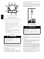
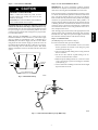
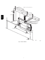
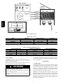
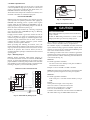
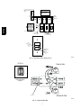
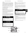
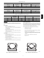
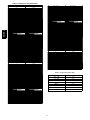
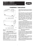
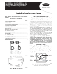
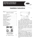
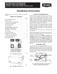
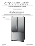
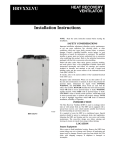
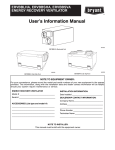
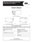
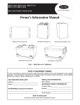
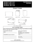
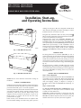
ERVCCSVA1100 ERVCCSHA1100
HRVCCSVA1100 HRVCCSHA1100
ENERGY/HEAT RECOVERY VENTILATOR
Installation, Start--up,
and Operating Instructions
clothing, and work gloves. Have fire extinguisher available. Read
these instructions thoroughly and follow all warnings or cautions
included in literature and attached to the unit.
Recognize safety information. This is the safety--alert symbol !
When you see this symbol on the unit and in instructions or manuals,
be alert to the potential for personal injury.
Understand these signal words; DANGER, WARNING, and
CAUTION. These words are used with the safety--alert symbol.
DANGER identifies the most serious hazards which will result in
severe personal injury or death. WARNING signifies hazards which
could result in personal injury or death. CAUTION is used to
identify unsafe practices which may result in minor personal injury
or product and property damage. NOTE is used to highlight
suggestions which will result in enhanced installation, reliability, or
operation.
A05229
Fig. 1 -- ERV/HRV Unit (Top Port)
INTRODUCTION
The Energy/Heat Recovery Ventilator (ERV/HRV) is used to
exchange indoor stale air with outside fresh air. The unit is equipped
with a special energy/heat recovery core which transfers both
sensible and/or latent heat between the fresh incoming air and stale
exhaust air. The cross--flow design core allows entering and leaving
air streams to transfer heat and/or latent energy without mixing (See
Fig. 14).
The model operates at 2 airflows, 50 CFM in low speed and 100
CFM in high speed. This unit comes in two configurations, vertical
or horizontal. Special attention should be given to duct application,
balancing the ERV/HRV, and locating unit for easy access and
routine maintenance.
A05330
INSTALLATION CONSIDERATIONS
Fig. 2 -- ERV/HRV Unit (Side Port)
Step 1.—Inspect Equipment
Move carton to final installation location. Remove ERV/HRV from
carton taking care not to damage unit. Remove all packaging and
inspect unit for damage. Remove parts bag from inside unit. File
claim with shipping company if shipment is damaged or
incomplete. Check to make sure ERV/HRV unit matches Fig. 1 or
Fig. 2.
NOTE: Read the entire instruction manual before starting the
installation.
SAFETY CONSIDERATIONS
Installation and servicing of this equipment can be hazardous due to
mechanical and electrical components. Only trained and qualified
personnel should install, repair, or service this equipment.
Step 2.—Select Location
The ERV/HRV should be located in a conditioned space and in
close proximity to a fused power source. It should be easily
accessible for routine maintenance.
Untrained personnel can perform basic maintenance functions such
as cleaning and replacing air filters. All other operations must be
performed by trained service personnel. When working on this
equipment, observe precautions in the literature, on tags, and on
labels attached to or shipped with the unit and other safety
precautions that may apply.
If ERV/HRV is installed independent of a forced--air system, unit
should be located near the center of the air distribution system. If
ERV/HRV is installed in conjunction with a forced--air system, unit
should be located next to (or close to) the indoor equipment.
Follow all safety codes. Installation must be in compliance with
local and national building codes. Wear safety glasses, protective
1
running both fresh--air and return--air registers (or stale--air pickup
registers) throughout the home.
ERV ports on side (bottom view)
4
5
3
8
2
1
7
ERV/HRV
Fresh--air registers are normally located in bedrooms, dining room,
living room, and basement. It is recommended that registers be
placed 6 to 12 in. from the ceiling on an interior wall and airflow
directed toward ceiling. If registers are floor installed, airflow
should be directed toward the wall.
4
6
A05263
Fig. 3 -- Conventional Horizontal Unit
COMPONENT DESCRIPTION
The following listed items are components of HRVCCLHA (See
Fig. 3).
1. Stale air return from building connected to return--air duct
system.
2. Fresh--air intake connected to outdoor air inlet hood.
3. Exhaust--air connected to outdoor air exhaust hood.
A05331
Fig. 4 -- Chain Spring Installation
4. Mechanical filters trap dust contained in the air.
5. Heat recovery core is a cross--flow type. The core transfers
heat between the 2 air streams.
!
6. Blowers bring in fresh--air from outside and exhaust
stale--air to outside.
CARBON MONOXIDE POISONING HAZARD
7. Electronic control circuit ensures proper unit operation.
Failure to follow this warning could result in personal
injury or death.
8. Fresh--air supply from HRV connected to return--air duct of
forced--air system.
Do not install return--air registers (or stale--air pickup
registers) in same room as gas furnace or water heater.
9. See Fig. 9 for terminal connector block for wiring wall and
timer contorls.
UNIT INSTALLATION
!
WARNING
Return--air (or stale--air pickup registers) are normally located to
draw from kitchen, bathroom, basement, or other rooms where
stale--air can exist.
CAUTION
Proper size and type of registers must be used to minimize pressure
drop. The velocity of airflow through register should not be above
400 ft/minute.
UNIT DAMAGE HAZARD
Failure to follow this caution may result in equipment
damage or improper operation.
Maximum length of duct for the system should be designed
according to the highest speed of the unit. Refer to specifications
listed in unit Product Data Digest for ventilation capacities.
Do not install ERV/HRV in a corrosive or contaminated
atmosphere.
Step 3.—Forced--Air Application
Most ERV/HRV applications will be installed in conjunction with
new or existing forced--air system. To operate properly, the fresh--air
supply and stale--air return from ERV/HRV connect directly to
return--air duct system. This is how the ERV/HRV distributes fresh
air and removes stale air from inside of building (See Fig. 7). For
these installations, furnace or fan coil blower must be interlocked
and operate continuously whenever ERV/HRV is energized.
Step 1.—Mount Unit
The ERV/HRV can be suspended from floor joists using chains and
4 springs. Attach metal hanging bracket to all 4 sides of cabinet (See
Fig. 4). The unit may be installed on a shelf if an isolation pad is
provided to dampen vibration. Unit should always be installed as
level as possible.
Step 2.—Independent System Application
NOTE: The fresh air from ERV/HRV is introduced into return--air
duct at a point no less than 10 ft upstream of furnace or fan coil. This
connection should be direct (See Fig. 7). This is to allow incoming
fresh--air to mix before entering indoor equipment.
In the absence of a forced--air system and a typical duct system
layout, the ERV/HRV can be applied as an independent or stand
alone unit. To ensure comfort, this type of application involves
2
Step 5.—Locate and Install Exterior Hoods
Step 4.— Connect Ducts to ERV/HRV
IMPORTANT: To prevent condensation problems, insulated
flexible ducts are required on both fresh--air inlet and exhaust--air
outlet ducts connecting between ERV/HRV and exterior wall.
CAUTION
PROPERTY DAMAGE HAZARD
Fresh--air intake and stale--air exhaust must be separated by at least
6 ft. Fresh--air intake must be positioned at least 10 ft. from nearest
dryer vent, furnace exhaust, driveway, gas meter, or oil fill pipe.
Fresh--air intake must be positioned as far as possible from garbage
containers and potential chemical fumes. When possible, it is
advised to locate the intake and exhaust hoods on same side of house
or building. The intake and exhaust hoods should never be located
on interior corners or in dead air pockets (See Fig. 7). Both intake
and exhaust hoods must be 18 in. from ground and at least 12 in.
above anticipated snow level.
Failure to follow this caution may result in minor
property damage from sweating duct or loss of unit
efficiency and capacity.
If ERV/HRV duct work is installed in an unconditioned
space, insulated flexible duct is required.
Insulated flexible duct is required on both fresh--air inlet and
exhaust--air outlet ducts connecting to exterior wall. When using
insulated flexible duct, the vapor barrier of the flexible ducts must
be taped very tight to prevent condensation problems. To reduce
pressure drop, stretch the flex duct and support it in a proper manner
to avoid reduced airflow.
After selecting proper hood locations, make appropriate size hole
through exterior wall, pass flexible duct through hole and insert
hood tube into duct. Tape duct vapor barrier tightly around hood
tube and insert assembly back into wall and fasten securely.
When connecting the ERV/HRV to a return--air duct system,
insulated flexible duct can be used. However, when metal or rigid
ducts are applied use approximately 18--in. of flexible duct at
ERV/HRV ports for fresh--air supply, and stale--air return. When
using metal duct from fresh--air supply to system duct work, the
metal duct should be insulated (See Fig. 5). This can act as a silencer
when connecting ducts to return--air duct system. This should
eliminate transmission of noise or vibration from unit to main duct
system.
Step 6.—Condensate Drain
(For ERV, skip Step 6 and continue to Step 7.)
To connect condensate drain, proceed as follows:
1. Punch out holes in foam insulation and door, then insert
sleeved grommets into bottom of unit using the gasket
washer and nut (See Fig. 6).
2. Cut two sections of plastic tubing, about 12” long and attach
them to each drain.
FLEXIBLE
DUCT
3. Join the two short sections of plastic tubing to the “T”
connector and the main tube as shown.
FRESH-AIR
SUPPLY
4. Make a loop in the tubing below the “T” connector to create
a trap to prevent sewer gases from entering the ventilation
system (See Fig. 6).
STALE-AIR
RETURN
5. Connect unit drain to building’s main drain. Provide slight
slope from unit for run--off.
DUCTS CONNECTING TO
RETURN-AIR DUCT SYSTEM
A98382
Fig. 5 -- Flexible Duct Fit--Up
A99268
Fig. 6 -- Condensate Drain With Loop Trap (HRV Only)
3
ERV/HRV
!
NOTE: A + B = Not less than 10 feet
A
3 Ft. MIN
B
ERV/HRV
FURNACE
INSULATED DUCT CONNECTING
FRESH AIR & EXHAUST TO
OUTSIDE
NOTE: Supply & exhaust ducts have
internal balancing dampers
that must be adjusted.
ERV
INLET HOOD
REAR
6′
EXHAUST HOOD
18″
GROUND LEVEL
A00111
A05358
Fig. 7 -- Exhaust Ventilation
4
WALL CONTROL
This control helps avoid condensation problems in upper northern
regions where indoor humidity is a problem during the winter
season.
Step 1.—Location
The ERV/HRV wall control is unique to this unit. The ERV/HRV
will not operate without it. This control senses humidity not
temperature. It must be located in an area where it will continually
monitor fresh air circulating within the home. Install ERV/HRV
wall control as close as possible to main system thermostat and
follow same guidelines as installing a thermostat (locate
approximately 5 ft. above floor, mount on an inside partitioning
wall, etc.)
NOTE:This control is not to be confused with a dehumidistat used
during the summer months to control high relative indoor humidity.
Table 2 recommends humidity levels to avoid condensation.
Step 5.—OneTouch Control
The OneTouch control can be used as the primary wall control for
the ERV/HRV. This control will step through the modes of operation
with consecutive presses of the button. The LED indicates which
mode is currently selected, Off, Intermittent, Low, or High.
Step 2.—Wiring
Remove top cover assembly from wall control and pass thermostat
wire through hole located on back of control before attaching to
wall. Connect Y, R, G, and B (yellow, red, green, and black) between
wall control and ERV/HRV connector following color code (See
Fig. 8 and 9). Replace top cover assembly. In Fig 9, item A shows
a correctly inserted wire, item B shows an incorrectly inserted wire.
NOTE: To ensure highest degree of humidity control in cooling
season, the INTERMITTENT mode should be used. See Table 1
and reference LOW and INTERMITTENT control operation listed
above.
NOTE: ERV/HRV wall control and circuit board operate on 12vdc.
NOTE: The ERV/HRV may be controlled using the Infinity system
control. The ERV/HRV may be connected using either a NIM or a
4--Zone Damper Module. See the appropriate instructions if using
the NIM of a 4--Zone Damper Module for connection instructions.
The Infinity system control will simultaneously control the
ERV/HRV and the indoor blower.
Push Button Timers may be used and are connected to the
ERV/HRV. However, the Infinity system should be set to
continuous fan to ensure that the fresh air is circulated in the home.
In a Zoned System, at least one zone should be set to continuous fan.
YELLOW
RED
GREEN
Y
R
GB
OPERATING THE ERV/HRV WITH
THE INFINITY CONTROL
BLACK
The ventilator has four settings in heating mode and three settings
in cooling mode.
A98383
Heating:
Fig. 8 -- Typical Wall Control
AUTO -- the ventilator selects the speed based on indoor
humidity and outdoor temperature. It may cycle on/off every
30 minutes depending on humidity and outside temperature.
Step 3.—Operation
The ERV/HRV wall control has 4 basic modes of operation, OFF,
LOW, HIGH, and INTERMITTENT. Be sure that all modes of
operation are fully functional. See Table 1 indicating standard
control operation.
LOW -- low speed all of the time.
HIGH -- high speed all of the time.
DEHUM -- will only turn on if humidity is 3% over set point.
The speed is determined by indoor humidity and outdoor
temperature.
1. With switch off, ERV/HRV is inoperative and the LED is
out.
2. With switch on LOW, ERV/HRV continuously exchanges
air with outside. If control is satisfied, blower will run in low
speed, otherwise, blower will run on high speed. The LED
is illuminated all the time.
Cooling:
AUTO -- the ventilator selects the speed based on indoor
humidity and outdoor temperature. It may cycle on/off every
30 minutes depending on humidity and outside temperature.
3. With switch on INTERMITTENT, the ERV/HRV
exchanges air with outside on high--speed blower, and unit
shuts down when control is satisfied. The ON LED is
illuminated all the time, and AIR EXCHANGE LED is
illuminated only when unit is running. This mode is ideal for
maintaining proper humidity levels when no one is home.
LOW -- low speed all of the time.
HIGH -- high speed all of the time.
If the fan speed is set to Auto and the ventilator wants to run, the fan
speed will run at High continuous speed. Otherwise, the fan will stay
at the chosen continuous fan speed.
Step 4.—Humidity Selector
The humidity selector is a built--in control designed to properly
control the level of humidity in the house during the winter months.
5
ERV/HRV
Step 6.—Latent Control
WALL CONTROL
MODE
CONTROL
CONNECTOR
AIR EXCHANGE
´
ECHANGE
D´AIR
50
60
MAINTENANCE
BLACK
% HUM. RELATIVE HUM. EXT. TEMP. EXT.
55%
10 C/50 F
40
45%
0 C/32 F
35%
–10 C/14 F
30
30%
–20 C/–4 F
70
GREEN
25
RED
20
80
YELLOW
ERV/HRV
% D´HUMIDITE´ RELATIVE HUMIDITY
A
WARNING
Risk of electric
shock. Beforeperforming
any maintenance or
servici
ng,alwa ys
disconnect the unit
om fr
it
s pow ersource.
CA UTION
B
AVER TISS EMENT
Danger ’é
dlectr
ocution.Débranchez
toujour
s ’l
a ppareil
avant ’entre
d
prendre
des tra
vaux ’d
entretien oué deparation.
r
AT TENTION
Un screw both screw s toopen the electrical
évi
D sser le
s deux vi
s pour ouvrir le par
com
timent
com partment.To complete
ly remove,detach électrique
.Pour retirer pl
com
ètement,le
fr
om it
s retention wire
side.
in
détacher de
son fil étention
de r
érieur
int
.
No light
OFF or remote controled
Amber light
LOW speed
Green ligh
HIGH speed
Blinking light
See User Manual
Sans lumi
ère
êté Arr
ou contr
ôlé
ôle mura l par contr
Lumière ambre
Basse vitesse
Lumière verte
Haute vitesse
Clignotant Voir guide
’utilisation
d
Terminal
Connector
A05334
Fig. 9 -- Control Connector
Table 1—Basic Control
MODE
Off
Low
Intermittent
High
OPERATION
Off
Air exchange with outside
Air exchange with outside
Air exchange with outside
DAMPER POSITION
Closed to outside
Open to outside
Open to outside
Open to outside
FAN SPEED
Off
Low
Low
High
Table 2—Recommended Humidity Levels
OUTSIDE TEMPERATURE
50° F
10° C
32° F
0° C
14° F
--- 10° C
---4° F
--- 20° C
---22° F
--- 30° C
DOUBLE ---PANE WINDOWS
55 percent
45 percent
35 percent
30 percent
25 percent
ELECTRICAL CONNECTIONS
2. 12--vdc Wiring
The ERV/HRV circuit board, wall control, and accessories operate
on 12vdc. See Wall Control section, item Wiring and Fig. 8 and 9
for more information.
1. 115--vac Wiring
The ERV/HRV operates on 115vac. It comes with a power cord
attached to unit and ready to plug into a fused outlet. Unit must be
grounded for proper operation.
ACCESSORIES
All electrical connections must comply with National and Local
Electrical Codes, or other ordinances that might apply.
!
TRIPLE ---PANE WINDOWS
65 percent
55 percent
45 percent
45 percent
35 percent
1. 20 Minute Timer
A push button timer can be used to override the wall control and put
the ERV/HRV into high speed for 20 minutes. Connect switches in
parallel and connect leads to ERV/HRV terminals I, OC, and OL
(See Fig. 12). Push button locations are ideal in special activity
areas, such as, bathroom, or kitchen, where high--speed exhaust
operation is needed for a short period of time.
WARNING
ELECTRICAL SHOCK / FIRE HAZARD
Failure to follow this warning could result in personal injury,
death and/or property damage.
NOTE: The 20 minute timer will not function properly unless
ERV/HRV wall control is applied and working correctly. Timing
function is internal to electronic circuit board, it is activated by a
momentary contact between OC and OL. The I connection is to
illuminate the push button. The maximum number of push button
timers that can be applied is 5.
Do not use an extension cord as a power source for operating the
ERV/HRV.
6
2. 60 Minute Adjustable Timer
A 60 minute adjustable timer can also be used to override wall
control and put HRV into high--speed operation for a select amount
of time. Connect timer in parallel with push button timers, or to
ERV/HRV terminals OC and OL (See Fig. 12).
The 60 minute timer will provide a minimum of 10 minutes, and a
maximum of 60 minutes of ventilation at high speed.
BALANCING ERV/HRV
A98400
Balancing intake and exhaust airflow is very important for proper
system operation and optimum performance when applying an
ERV/HRV. Unit balancing prevents a positive and/or negative
pressure within the home. Balancing the ERV/HRV is done by
applying magnehelic gage and balancing dampers to the fresh air
intake and stale air exhaust ducts (See Fig. 11).
Fig. 11 -- Magnehelic Gage
VENTILATION EVALUATION
UNIT DAMAGE HAZARD
Failure to follow this caution may result in reduced unit efficiency,
capacity or unit life.
If supply--air from outside is greater than exhaust--air from the
house, an imbalance can result over pressurizing the home. If
exhaust--air is greater than supply--air, combustion appliances may
backdraft, bringing exhaust fumes into the house. A balanced
condition will ensure optimum performance, provide satisfied
customers, and avoid expensive callbacks.
DO NOT use HRV during construction of a house or when
sanding drywall. This type of dust may damage system.
When ventilation requirement is determined, use Product Data
Sheets to reference unit airflow delivery and performance.
Before proceeding with balancing, all windows, doors, and
fireplace flues should be tightly closed. No exhaust systems such as
range top exhausts, dryer exhaust, fume hoods, bath or roof fans
should be in operation. The forced--air furnace (if used for
circulation) should be operating in continuous fan mode for normal
operating speed.
The ventilation capacity of an ERV/HRV unit while at maximum
speed is defined according to greatest total airflow required. These
methods are derived from the Canadian National Building Code
1995 version and the CSA F326.1 revision.
The following 2 methods can be used to evaluate the approximate
ventilation needs of a house. Accuracy of calculations are dependent
upon the information available and knowing critical measurements
of the structure (See Fig. 15).
Step 1.—Balancing Dampers
Balancing dampers (sometimes called butterfly dampers) are
located in fresh--air intake and stale--air exhaust of the ERV/HRV.
(See Fig. 13). Some field modification may be required to ensure
proper installation of balancing dampers while located in flexible
duct. Insulating over these dampers is strongly recommended after
balancing is complete to prevent condensation problems.
METHOD 1
To calculate approximate ventilation:
The sum of rooms X 10 CFM per room, plus 20 CFM for a
master bedroom or basement.
Example: 8 rooms X 10 CFM + 20 CFM = 100 CFM.
STANDARD FURNACE INTERLOCK WIRING
G
Y
THERMOSTAT
TERMINALS
FOUR
WIRES
TWO WIRES
heating only
R
G
To calculate approximate ventilation:
Total cu ft X per hr = total. Take total and divide by 60 to get
CFM.
CONNECTOR
W
METHOD 2
UNIT TERMINAL
R
NOTE: The master bedroom and basement are not included in first
part of this equation, but figured in at second part of equation.
NO C NC I OCOL Y R G B
W
Example:
1220 sq ft X 8 ft in height = 9760 cu ft per floor
9760 cu ft x 2 floors = 19520 total cu ft in house
19520 cu ft X .3 air changes per hr = 5856 cu ft
5856 cu ft ÷ 60 minimum per hr = 98 CFM.
C
FURNACE
24-VOLT
TERMINAL BLOCK
TWO WIRES
CONDENSING UNIT
Y
CAUTION
Conclusion: The total amount of air flow needed is 98 CFM. This
falls within airflow range of a ERVCCSHA1100 size unit.
A05344
Fig. 10 -- Interlock Relay Wiring Layout
7
ERV/HRV
!
Airflow is temporarily determined by connecting a magnehelic
gage to the pressure taps on ERV/HRV (See Fig. 13). Balancing
chart is located on unit door.
J3
ELECTRONIC CONTROL
BOARD
THE WIRES FROM THE SWITCH
9
8
7
6
OL 5
OC 4
I 3
YELLOW – INDICATOR, (J3--3)
BLACK – COMMON, (J3--4)
RED – SWITCH, (J3--5)
RED
BLACK
YELLOW
ERV/HRV
J1
1
4
7
2
5
8
3
6
9
(OPTIONAL)
60 MINUTE TIMER
(OPTIONAL)
PUSH BUTTON SWITCHES
(5 SWITCHES MAXIMUM)
(OC)
BLACK – (J3- 4)
COMMON
TERMINAL
STRIP
(I)
YELLOW – (J3- 3)
INDICATOR
TERMINAL STRIP
RED – (J3- 5)
SWITCH
TERMINAL STRIP
(OL)
BACK OF PUSH BUTTON SWITCH
A98386
Fig. 12 -- Push Button Timer Wiring Layout
DETAIL A
Fresh air flow
Port with integrated
balancing damper
Top View
SEE DETAIL A
Exhaust Air Flow
A05333
Fig. 13 -- Balancing ERV/HRV
8
CARE AND MAINTENANCE
CONTROL BOARD OPERATION
1. Defrost
1. Door
The ERV/HRV continually monitors the outside air temperature. If
the outside air is at or below 23°F(--5°C), the ERV/HRV will initiate
a defrost cycle by closing the outside air damper and recirculating
warm indoor air through the heat recovery core. This happens every
32 min. with 6 minute defrost cycle. During this process, core is
defrosted without the use of electric strip heat. At 5°F(--15°C), unit
will defrost for 6 minutes every 32 min. At --17°F(--27°C), the unit
will sense a need to defrost every 20 minutes with a 6 minute cycle.
See the Troubleshooting section for a control logic explanation.
ERV/HRV door can be removed by unlatching brief case style
latches, then slide door to the right and remove it from hinges. Door
must be in place and secured shut for proper operation.
2. Filter
Filters in ERV/HRV are washable and should be cleaned every 3
months. Use a vacuum cleaner to remove heaviest portion of
accumulated dust, then wash in lukewarm water. Allow filter to
completely dry before reinstalling. A dirty air filter will cause
excessive strain on blower motor. Never operate unit without a filter.
Vacuum out debris.
2. Off and Intermittent/Off Mode
When ERV/HRV is Off, K1 relay is open, and K5 relay is energized
which closes outside air damper.
In addition, regularly check and clean screens on exterior intake and
exhaust hoods when necessary.
UNIT COMPONENT DAMAGE HAZARD
Failure to follow this caution may result in unit
component damage.
DO NOT clean filters in a dishwasher and DO NOT dry
them with a heating appliance or permanent damage will
result.
4. Low--Speed Air Exchange
When low--speed air exchange occurs, K1 Relay is energized which
closes the contacts. K2 and K5 relays are de--energized. This keeps
low--speed contacts closed and high--speed contacts open on K2
relay, and opens outdoor air damper. 120vac is applied between Red
and Gray wires on Molex plug (pins 1 and 4) and blower motor runs
in low--speed operation.
!
3. Blower Motor and Wheel
ERV/HRV blower motors are factory lubricated for life. Lubricating
bearings is not recommended. However, inspect and clean any
accumulated dirt and grease from blower motor and wheel annually.
4. Cleaning the Core
WARNING
ERV is equipped with a special energy recovery core which utilizes
a special membrane and allows transfer of sensible and latent
energy. The core should always be vacuumed only every 3 months
to remove dust and dirt that could prevent transfer of energy (See
Fig. 16 and 17).
ELECTRICAL SHOCK HAZARD
Failure to follow this warning could result in personal
injury or death.
Before installing or servicing system, always turn off
main power to system. There may be more than 1
disconnect switch.
!
CAUTION
!
When high--speed air exchange occurs, K1 and K2 relays are
energized and K5 relay is de--energized. This opens low--speed
contacts, and closes high--speed contact on K2 relay. This also opens
contact on K5 relay which opens outside air damper. Then, 115vac
is applied between orange and gray wires on Molex plug (pins 1 and
6) and blower motor runs in high--speed operation.
ERV/HRV
3. High--Speed Air Exchange
NOTE: The core should only be serviced when outdoor
temperature is between 60°F and 75°F and it is dry.
CAUTION
CUT HAZARD
Failure to follow this caution may result in personal
injury.
Sheet metal parts may have sharp edges or burrs. Use
care and wear appropriate protective clothing and gloves
when handling parts.
FRESH AIR
TO BUILDING
STALE AIR
TO OUTSIDE
FRESH AIR
FROM OUTSIDE
STALE AIR
FROM BUILDING
A05346
Fig. 14 -- ERV/HRV Airflow During Air Exchange
9
MASTER
BEDROOM
WASHROOM
#1
WASHROOM
#2
WASHROOM
#6
BEDROOM
#3
LIVING ROOM
#5
BEDROOM
#4
KITCHEN
#7
DINING ROOM
#8
1220 sq ft (113 sq m)
1220 sq ft (113 sq m)
A05359
Fig. 15 -- Floor Plan Example
ERV/HRV
!
TROUBLESHOOTING
CAUTION
NOTE: Reference Table 3 Troubleshooting Chart
UNIT COMPONENT DAMAGE HAZARD
This can be a quick guide in resolving unit problems. It is also
recommended to review and understand Wall Control Board
Operation and Care and Maintenance sections before continuing.
There are 3 main parts to focus on when troubleshooting ERV/HRV
unit:
Failure to follow this caution may result in equipment
damage or improper operation.
DO NOT use water to clean core or damage will result.
In addition, before servicing or removing the core
inspect the edges to see if they appear soft (or slightly
expanded). This can be normal and due to moisture in
the air. DO NOT handle or service core until it is dry or
air passages can become damaged and/or closed.
1. Wall Control
2. Electronic control board
3. Blower motor
1. Wall Control
Typically, the wall control is either good or it is bad. Use Table 1 to
determine if wall control is operating correctly. Use Fig. 9 to check
control wire connections.
WARNING
!
NOTE: The electronic control board and wall control operate on
12vdc.
ELECTRICAL SHOCK HAZARD
Failure to follow this warning could result in personal
injury or death.
2. Control Board
Electronic control board must have wall control attached before unit
will function properly (except for units equipped with manual
switch such as the new horizontal units). Outside air thermistor must
be connected to control board for it to operate properly. See Table
6, Temperature --vs-- Ohm Chart, for valid temperature range.
Before installing or servicing system, always turn off
main power to system. There may be more than 1
disconnect switch.
3. Blower Motor
!
CAUTION
The ERV/HRV blower motor operates on 115vac, with 2--speed
operation.
The easiest way to check blower speed operation is to use the wall
control and initiate a low--speed blower and high--speed blower
operation.
CUT HAZARD
Failure to follow this caution may result in personal
injury.
NOTE: If there is a short circuit or an open circuit at thermistor,
CPU will go into a 5 minute defrost cycle every 20 minutes. This
feature is not there on older board versions with 3pin jumpers.
Sheet metal parts may have sharp edges or burrs. Use
care and wear appropriate protective clothing and gloves
when handling parts.
Table 3—Troubleshooting Chart
SYMPTOMS
Air too humid
Unit not responding to wall control
Unit stops momentarily
Air from distribution register too cold
Unit makes annoying noise
Noise level too high at distribution
registers when in high speed
CAUSES
Continuous exchange mode
used in small houses
Defrost condition is in effect
Outdoor temperature is below 23°F
Broken control wire
Electrical supply interrupted
Improper calibration of air flow
Ventilation wheel out of adjustment
Air duct system too short
10
SOLUTIONS
Use Intermittent Mode
Check humidity level settings
Unit will operate when not in defrost mode.
Defrost cycle is based on outdoor ambient (See Table 10)
Test wall control
Check connections
Check thermistor
Check units circuit breaker
Check calibration of flow rates
Remove the motor and screw wheel on properly
Install a duct silencer
Table 4—Defrost Cycle
HRV Defrost Cycles
Operation time (min.)
Defrosting (min.)
between each defrost cycle
7
25
10
22
Outside Temperature
Celcius (°C)
Fahrenheit (°F)
--- 5 to --- 27
--- 27 and less
23 to --- 17
--- 17 and less
Outside Temperature
Celcius (°C)
Fahrenheit (°F)
--- 5 to --- 27
--- 27 and less
23 to --- 17
--- 17 and less
ERV Defrost Cycles
Operation time (min.)
Defrosting (min.)
between each defrost cycle
9
23
10
22
CONTROL MODULE
Terminal Block
Terminal Block No.
Identification
J3 ---9
B
J3 ---8
G
J3 ---7
R
J3 ---6
WALL CONTROL
WALL CONTROL WIRE
Y
Color
Terminal No.
Terminal Identification
Black
Green
Red
Yellow
J1 ---4
J1 ---3
J1 ---2
J1 ---4
B
G
R
Y
Override Test
4. Blower Speed Selection
To use override test function, a thermistor must be connected to the
control board. Unit must not be in defrost mode during an override
test.
Three--speed blowers are factory connected to electronic control
board on HIGH-- and LOW--speed taps of blowers. Installer can
easily change low--speed tap to medium--speed tap so electronic
control will select between high and medium speed. Connections
can be changed at motor location (See Table 6 and 7).
HIGH SPEED
1. Disconnect ERV/HRV from 115vac.
1. Unplug wall control wires at control module terminal block
inside ERV/HRV.
To change low speed to medium speed, proceed as follows:
1. Unplug unit from 115vac.
2. Plug ERV/HRV back to 115vac.
2. Locate blower assembly.
3. Attach a wire across J3--8 and J3--9 (B and G) on control
module terminal block.
3. Locate red wire anb lue wire coming from blower assembly.
4. Unplug red wire from quick connect.
4. Push in door switch, this will initiate a high--speed exchange.
5. Unplug protecting cap quick connection from blue wire and
put on red wire coming from blower. The cap is a safety
insulator.
LOW SPEED
1. Unplug ERV/HRV from 115vac.
6. Connect red wire of main harness to blue wire.
2. Disconnect wall control wires at control module terminal
block inside ERV/HRV.
7. Replace wires.
3. Plug ERV/HRV back to 115vac.
4. Connect a 3.0 K ohm resistor between B and G on control
module terminal block.
5. Push in door switch, this will initiate a low--speed exchange.
A05347
A05348
Fig. 16 -- ERV Ports on Side (Bottom View)
Fig. 17 -- HRV Ports on Side (Bottom View)
11
ERV/HRV
Table 5—System Wiring Colors and Connections
ERV/HRV
Table 6—Temperature/Ohm Relationship
Temp. (deg. C)
--- 50
--- 49
--- 48
--- 47
--- 46
--- 45
--- 44
--- 43
--- 42
--- 41
--- 40
--- 39
--- 38
--- 37
--- 36
--- 35
--- 34
--- 33
--- 32
--- 31
--- 30
--- 29
--- 28
--- 27
--- 26
--- 25
--- 24
--- 23
--- 22
--- 21
--- 20
--- 19
--- 18
--- 17
--- 16
--- 15
--- 14
--- 13
--- 12
--- 11
--- 10
--- 9
--- 8
--- 7
--- 6
--- 5
--- 4
--- 3
--- 2
--- 1
0
1
2
3
4
5
6
7
8
9
10
11
12
13
14
15
16
17
18
19
20
21
22
23
24
25
26
27
28
29
30
31
32
33
34
35
36
37
38
39
40
41
42
43
44
Rst. (k Ohms)
329.5
310.9
293.5
277.2
262.0
247.7
234.3
221.7
209.9
198.9
188.5
178.5
169.0
160.2
151.9
144.1
136.7
129.8
123.3
117.1
111.3
105.7
100.5
95.52
90.84
86.43
82.26
78.33
74.61
71.10
67.77
64.57
61.54
58.68
55.97
53.41
50.98
48.68
46.50
44.43
42.47
40.57
38.77
37.06
35.44
33.90
32.44
31.05
29.73
28.48
27.28
26.13
25.03
23.99
23.00
22.05
21.15
20.30
19.48
18.70
17.96
17.24
16.56
15.90
15.28
14.69
14.12
13.58
13.06
12.56
12.09
11.63
11.20
10.78
10.38
10.00
9.632
9.281
8.944
8.622
8.313
8.014
7.728
7.454
7.192
6.940
6.699
6.467
6.245
6.032
5.827
5.629
5.438
5.255
5.080
Temp. (deg. C)
45
46
47
48
49
50
51
52
53
54
55
56
57
58
59
60
61
62
63
64
65
66
67
68
69
70
71
72
73
74
75
76
77
78
79
80
81
82
83
84
85
86
87
88
89
90
91
92
93
94
95
96
97
98
99
100
101
102
103
104
105
Rst. (k Ohms)
4.911
4.749
4.593
4.443
4.299
4.160
4.026
3.896
3.771
3.651
3.536
3.425
3.318
3.215
3.116
3.020
2.927
2.838
2.751
2.668
2.588
2.511
2.436
2.364
2.295
2.228
2.163
2.100
2.039
1.980
1.924
1.869
1.816
1.765
1.716
1.668
1.622
1.577
1.533
1.492
1.451
1.412
1.373
1.336
1.301
1.266
1.232
1.200
1.168
1.137
1.108
1.079
1.051
1.024
0.9984
0.9731
0.9484
0.9246
0.9014
0.8789
0.8572
Table 7—Temperature and Voltage
TEMP °F (°C)
---22 (---30)
---4 (---20)
4 (---15)
14 (---10)
32 (0)
41 (5)
50 (10)
68 (20)
12
Voltage DC Volts (J4)
3.5
2.7
2.3
2.0
1.4
1.1
0.9
0.6
13
K5 K2 K3 K1
0 0 0 0
1 0 1 1
1 1 1 1
1 1 1 0
1 1 1 0
GRN
BLK
BLK
BLK
BLK
BLK
BLK
BLU
BLU
BRN
BRN
MODE
OFF
Exchange low speed
Exchange high speed
Circulation high speed
Defrost
M2
C2
Supply fan motor
capacitor
Supply fan motor
C1
M1
Exhaust fan motor
capacitor
Exhaust fan motor
GRN
CONNECTION DIAGRAM
Class 2 low voltage field wiring
Class 2 low voltage factory wiring
Line voltage factory wiring
neutral
68V
90V
J9
J8
9.5V
class 2
BRN
1
WHT
GRN
BLK
2
4 3 2 1
J10
W1
BRN
M2 - "Exhaust"
OFF
LO
HI
OFF
OFF
F1
Y
BLK
5 4 3 2 1
Y
24V class 2
See note 1
120V, 60Hz
1
2 J4
3
2
1 J6
2
1 J7
T1
M3
1
2 J5
3
M1 "Supply"
OFF
LO
HI
HI
HI
WHT
RED
BLU
BLK
120V
Damper motor
BLK
WHT
J12
J11
DAMPER
Closed
Opened
Opened
Closed
Closed
1 2
J2
WHT
Door interlock
switch
(magnetically
actuated reed
switch)
S1
ICP
J13
2 1
A2
J1
10
9
8
7
6
5
4
3
2
1
J14
to
BLK
GRN
YEL
Furnace blower interlock
J14-1 : NO
J14-2 : COM
J14-3 : NC
(see notes 3, 5)
RED
BLACK
BLUE
BROWN
GREEN
GRY
ORANGE
RED
WHITE
YELLOW
Override switch
(optional; see notes
3, 4)
Defrost temperature
sensor
Field wiring
remote control
(see notes 3, 4)
R1
BLK
BLU
BRN
GRN
GRY
ORG
RED
WHT
YEL
COLOR CODE
neutral
68V
90V
120V
Fig. 18 -- ERV/HRV Wiring Diagram
MODELS
HRVCCSHA1100, HRVCCSVA1100,
ERVCCSHA1100, ERVCCSVA1100,
ELECTRONIC ASSEMBLY
1 2 3 4 5
1 2
5 4 3 2 1
J3
DAMPER ELECTRONIC
ASSEMBLY
5. Furnace fan circuit must be class 2 circuit only.
4. Remote controls available. See instruction manual. (class
2 circuit)
3. Field wiring must comply with applicable codes,
ordinances and regulations.
2. If any of the original wire, as supplied, must be replaced,
use the same equivalent wire.
1. For continued fire protection, use specified UL
listed/CSA Certified line fuse.
9.5V
class 2
24V class
2
J8-5
J8-4
J8-2
J8-1
J9-4
J9-3
J9-2
J9-1
F1
J10-2
120V, 60Hz
LINE
CPU
K2
K3
K1
K5
K4
K2
ERVHRV
NC
K4
K3
K1
J11-1
J11-2
J12-1
J12-2
J12-3
J12-4
J12-5
LOGIC DIAGRAM
J6-1
J6-2
J4-3
J4-1
J7-1
J7-2
J5-3
J5-1
K5
A1
J2-1
J2-2
J2-3
J2-4
J2-5
J14-10
J14-9
J14-7
J14-8
J14-5
J14-6
J14-4
J14-2
J14-1
J14-3
J3-1
J3-2
A2
Supply fan motor
capacitor
Supply fan motor
Exhaust fan motor
capacitor
Exhaust fan motor
A05345
Field wiring wall control
(see notes 3, 4)
Override
(optional; see notes 3, 4)
AIR HANDLER
FAN INTERLOCK
24 VAC
CLASS 2 CIRCUIT ONLY
(optional; see notes 3, 5)
Door interlock magnetic switch
Damper motor
J4-2
J5-2
J10-1
120V, 60Hz
RETURN
ERV/HRV
Copyright 2005 Carrier Corp. S 7310 W. Morris St. S Indianapolis, IN 46231
Printed in U.S.A.
Manufacturer reserves the right to change, at any time, specifications and designs without notice and without obligations.
14
edition date: 11/05
Catalog No: ERVHRV--- 1SI
Replaces: New