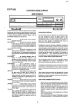
1
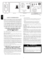
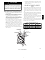
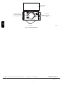
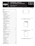
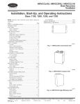
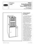
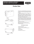
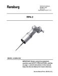
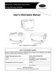
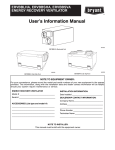
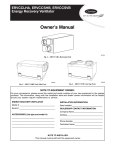
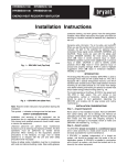
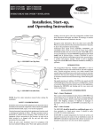
Heat Recovery
Ventilator
HRVBBLHA, HRVCCLHA,
HRVBBSVU, HRVCCSVU,
HRVBBLVU, HRVCCLVU,
HRVBBSVB, HRVCCSVB,
HRVBBSHB, HRVCCSHB
Owner’s Guide
HRVBBSVU, HRVCCSVU
HRVBBLHA, HRVCCLHA Conventional Unit
HRVBBSVB, HRVCCSVB Unit (Top Port)
HRVBBLVU, HRVCCLVU High Efficiency Unit
HRVBBSHB, HRVCCSHB (Side Port)
A11172
Fig. 1 -- Heat Recovery Ventilators
NOTE TO EQUIPMENT OWNER:
For your convenience, please record the model and serial numbers of your new equipment in the spaces
provided. This information, along with the installation data and dealer contact information will be helpful
should your system require maintenance or service.
HEAT RECOVERY VENTILATOR
INSTALLATION INFORMATION:
Model # _____________________________________
Date Installed ________________________________
Serial # ______________________________________
DEALERSHIP CONTACT INFORMATION:
Company Name_______________________________
ACCESSORIES (List type and model #)
Address______________________________________
_____________________________________________
_____________________________________________
_____________________________________________
_____________________________________________
Technician Name _____________________________
_____________________________________________
Phone Number _______________________________
_____________________________________________
NOTE TO INSTALLER:
This manual must be left with the equipment owner.
80
70
60
AIR EXCHANGE
´
ECHANGE
D´AIR
MODE
ON
MARCHE
50
OFF LOW HIGH
40
MAX
MIN
20
AIR EXCHANGE
´
ECHANGE
D´AIR
30
INTERMITTENT
25
´ RELATIVE HUMIDITY
% D´ HUMIDITE
ARRET
50
OFF
LOW
ARRET
BASSE
INTERMITTENT
BASSE HAUTE
60
% HUM. RELATIVE HUM.
55%
45%
35%
30
30%
40
70
% HUM. RELATIVE HUM.
55%
45%
35%
30%
EXT. TEMP. EXT.
10°C/50°F
0°C/32°F
–10°C/14°F
–20°C/–4°F
80
EXT. TEMP. EXT.
10°C/50°F
0°C/32°F
–10°C/14°F
–20°C/–4°F
25
20
´ RELATIVE HUMIDITY
% D´HUMIDITE
OneTouchTM Control
Standard Control
Basic Control
Automatic Control
(Not compatible with the following series: HRVBBSHB
HRVCCSHB, HRVBBSVB and HRVCCSVB)
HRV
A11173
Fig. 2 -- Controls
SAFETY CONSIDERATIONS
Recognize safety information. This is the safety--alert symbol
When you see this symbol on the unit and in instructions or
manuals, be alert to the potential for personal injury. Understand
these signal words; DANGER, WARNING, and CAUTION. These
words are used with the safety--alert symbol. DANGER identifies
the most serious hazards which will result in severe personal injury
or death. WARNING signifies hazards which could result in
personal injury or death. CAUTION is used to identify unsafe
practices which would result in minor personal injury or product
and property damage. NOTE is used to highlight suggestions
which will result in enhanced installation, reliability, or operation.
OPERATING YOUR HEAT RECOVERY
VENTILATOR (HRV) WITH
ONE TOUCHT CONTROL:
Press “PUSH” until the desired ventilation operation is selected.
There are three selections:
High, Low, Intermittent. The power indicator light indicates which
mode has been selected.
High: This mode is recommended for the removal of excess
pollutants and humidity. The ventilator will operate at its
maximum speed continuously. The power indicator light will be lit
red when this mode is selected.
Low: This mode is recommended for normal daily operation. The
ventilator will operate at its minimum speed continuously. The
power indicator light will be lit yellow when this mode is selected.
Intermittent: This mode is recommended when the inside air is too
dry in the heating season or too humid in the cooling season. The
ventilator will operate at its minimum speed for 20 minutes per
hour and be off for 40 minutes per hour. The power indicator light
will be lit green when this mode is selected.
Off: To turn the ventilator off, press “Push” until the power
indicator light is turned off.
may be unit mounted.
S Standard Controls: Offer automatic dehumidistat control and the
option to select low speed or intermittent fan during heating
season.
S Automatic Controls: In addition to the operational features
found with standard controls, automatic controls feature a
recirculation mode. Not for use with forced--air HVAC systems.
Fan Speed Control — Enables user to modulate fan speed from
low to high.
Dehumidistat Control — Allows the user to select the relative
humidity level at which the unit would change fan speed to avoid
condensation problems while heating during the winter months.
(See Table 1).
Continuous Mode — If the relative humidity inside the building
is lower than selected, air exchange would occur with the outside at
low speed. If the relative humidity level inside the building is
higher than selected, air exchange would occur outside at high
speed. This ensures continuous air exchange for constant air
quality.
Intermittent Mode — If the relative humidity inside the building
is lower than selected, no air exchange would occur, and the
system would turn off. If the relative humidity inside the building
is higher than selected, air exchange would occur with outside at
high speed. This ensures minimum air exchange level when the
building is unoccupied to minimize operating cost.
Recirculation Mode — If the relative humidity inside the building
is lower than selected, indoor air would be circulated and filtered at
high speed. If the relative humidity inside the house is higher an
selected, air exchange would occur with outside at high speed. This
ensures continuous movement and filtration of air for maximum
comfort.
!
OPERATING YOUR HEAT RECOVERY
VENTILATOR (HRV) WITH BASIC,
STANDARD AND AUTOMATIC CONTROL
WARNING
ELECTRICAL OPERATION HAZARD
Failure to follow this warning could result in personal injury
or death.
Before servicing system, always turn off main power to
system. Turn off accessory heater power if applicable. There
may be more than 1 disconnect switch.
Your HRV is designed to operate as an integral part of your total
heating and cooling system. With the exception of high capacity
models, which are available with standard controls only, all HRVs
offer 4 control options (See Fig. 2).
S Basic Controls:Allow the user to manually set the unit to low-or high-- fan speed as required to maximize comfort. Controls
2
5. Examine the condensate drain pan to ensure drains are functioning properly. Gently clean tray with mild soapy water.
(See Fig. 3 and Fig. 4).
CAUTION
CUT HAZARD
BEFORE YOU REQUEST A SERVICE
CALL
Failure to follow this caution may result in personal injury.
Although special care has been taken to minimize sharp edges
in the construction of your unit, be extremely careful when
handling parts or reaching into the unit. Wear appropriate
protective clothing and gloves when working on this unit.
PERFORMING ROUTINE MAINTENANCE
1. The motors are factory lubricated. Lubricating the bearings
is not recommended.
2. The heat recovery coremust be handled with care. To ensure
maximum efficiency of the plastic partitions wash core once
a year following the season of most intense use.
Allowthe heat recovery core to soak for 3 hours in a
solution ofwarmwater and mild soap. Rinse under a stream
ofwarm water. Hot water and strong detergent should NOT
be used,as it will damage the heat recovery core.
3. A dirty air filter will cause excessive strain on the blower
motor. The filters in your HRV are washable and should be
cleaned every 3months.Use a vacuumcleaner to remove the
heaviest portion of accumulated dust, then wash in warm
water.
The Air Exchange Indicator light on the auto control will
indicate when filters should be cleaned. The light will flash
on and off until the door is opened to service the unit.
4. Regularly check the screen on the exterior intake hood and
clean as necessary.
S Check the main power disconnect switch. Verify that the circuit
breakers are ON or that fuses have not blown. If you must reset
breakers or replace fuses, do so only once. Contact your servicing
dealer for assistance if the breakers trip or the fuses blow a second
time.
S Check for sufficient airflow. Check air filters for accumulations of
large particles. Check for blocked exhaust--air grilles or ductwork.
Keep grilles and duct work open and unobstructed.
S If the condensate fails to drain properly, check the grommet and
drain tube for obstructions. Make sure that the condensate drain
tube has a slight slope and is not kinked.
If your HRV still fails to operate properly, contact your servicing dealer. Give him your model and serial number. With this information, the
dealer will be able to correct any problems.
Table 1 – Recommended Humidity Levels
OUTSIDE
TEMPERATURE
50°F / 10°C
32°F / 0°C
14°F / --- 10°C
--- 4°F / --- 20°C
--- 22°F / --- 30°C
DOUBLE ---PANE
WINDOWS
55%
45%
35%
30%
25%
TRIPLE ---PANE
WINDOWS
65%
55%
45%
45%
35%
FRESH AIR
TO BUILDING
FRESH AIR
FROM OUTSIDE
STALE AIR
FROM BUILDING
STALE AIR
TO OUTSIDE
A92382
Fig. 3 -- Vertical Application
3
HRV
!
DOOR IS
DETACHABLE
HRV
ENERGY RECOVERY
CORE CAN BE REMOVED
BY PULLING STRAIGHT OUT
FILTERS ARE
REMOVABLE BY
PULLING STRAIGHT
OUT
BRIEF CASE
TYPE LATCH
A99300
Fig. 4 -- Horizontal Application
Copyright 2011 CAC / BDP D 7310 W. Morris St. D Indianapolis, IN 46231
Printed in U.S.A.
Edition Date: 05/11
Manufacturer reserves the right to change, at any time, specifications and designs without notice and without obligations.
4
Catalog No: OG ---HRV ---01
Replaces: OMHRV--- 03BR
OMHRV--- 03CA