1
DIGITA
L SUPER
HYBR
ID
SYSTE
M
RUN
OFF
LINE
ALARM
Digital Super Hybrid System
Installation Manual
Model No.
KX-TD500
Please read this manual before connecting the Digital Super Hybrid System
and save this manual for future reference.
Thank you for purchasing the Panasonic Model KX-TD500, Digital Super Hybrid System.
Thank you for purchasing the Panasonic Model
KX-TD500, Digital Super Hybrid System.
2
Installation Manual
System Components
System Components
System Components Table
Model
Description
Shelves
KX-TD500
KX-TD520
Basic Shelf
Expansion Shelf
Extension
Cards
KX-T96170
KX-T96172
KX-T96174
KX-T96175
KX-T96185
KX-TD50170
KX-TD50172
KX-TD50175
HLC (Hybrid Line Circuit) Card
PLC (Proprietary Line Circuit) Card
SLC (Single Line Telephone Circuit) Card
SLC-M (Single Line Telephone Circuit with Message Waiting) Card
OPX (Off Premise Extension) Card
DHLC (Digital Hybrid Line Circuit) Card
DLC (Digital Proprietary Line Circuit) Card
ESLC (Enlarged Single Line Telephone Circuit with Message
Waiting) Card
Trunk Cards
KX-T96180
KX-T96181
KX-T96182
KX-T96187
KX-TD50180
KX-TD50288
KX-TD50290
LCOT (Loop Start Central Office Trunk) Card
GCOT (Ground Start Central Office Trunk) Card
DID (Direct Inward Dialing Trunk) Card
T1 Digital Trunk Card
ELCOT (Enhanced Loop Start Central Office Trunk) Card
BRI (ISDN Basic Rate Access Interface) Card
PRI23 (ISDN Primary Rate Access Interface) Card
Resource
Cards
KX-T96191
KX-T96193
KX-T96196
KX-TD50197
DISA (Direct Inward System Access) Card
AGC (Automatic Gain Control) Card
RMT (Remote Circuit) Card
ERMT (Enhanced Remote Circuit) Card
Other Cards
KX-T96136
KX-T96161
KX-TD193
KX-TD50101
OHCA (Off-Hook Call Announcement) Card
DPH (Doorphone Circuit) Card
Caller ID Card
CPU Card
Warning
This is a Class A product. In a domestic environment this product may
cause radio interference in which case the user may be required to take
adequate measures.
Installation Manual
3
System Components
Note
The power supply voltage of the main unit may differ from the values described in this manual
depending on the suffix of the model number, please consult your dealer for detailed
information.
System Components Table
Model
Description
KX-T7020
KX-T7030
KX-T7050
KX-T7055
APT with SP-PHONE (12-CO)
APT with SP-PHONE, 1-Line Display (12-CO)
APT with MONITOR (12-CO)
APT with MONITOR (3-CO)
KX-T7130
APT with SP-PHONE, 1-Line Display (12-CO)
KX-T7220
KX-T7230
KX-T7235
KX-T7250
DPT with SP-PHONE (24-CO)
DPT with SP-PHONE, 2-Line Display (24-CO)
DPT with SP-PHONE, 6-Line Display (12-CO)
DPT with MONITOR (6-CO)
KX-T7420
KX-T7425
KX-T7431
KX-T7433
KX-T7436
DPT with SP-PHONE (12-CO)
DPT with SP-PHONE (24-CO)
DPT with SP-PHONE, 1-Line Display (12-CO)
DPT with SP-PHONE, 3-Line Display (24-CO)
DPT with SP-PHONE, 6-Line Display (24-CO)
Single Line
Telephones
(SLTs)
KX-T7051
KX-T7052
SLT with FLASH button and Message Waiting Lamp
SLT with FLASH button and Message Waiting Lamp
Proprietary
Equipment
KX-T7040
DSS Console (32-DSS, 16-PF)
KX-T7240
DSS Console (32-DSS, 16-PF)
KX-T7440
KX-T7441
DSS Console (66-DSS)
DSS Console with ANSWER and RELEASE buttons (48-DSS)
KX-T96186
KX-T30865
KX-T7090
KX-A46
Off Premise Extension (OPX) Power Unit
Doorphone
Headset
Battery Adaptor
Analog
Proprietary
Telephones
(APTs)
Digital
Proprietary
Telephones
(DPTs)
Notes
• CO: CO line access button
• DSS: Direct Station Selection button
• PF: Programmable Feature button
4
Installation Manual
System Components
Trademarks
• Microsoft, Windows and Windows NT are either registered trademarks or trademarks of
Microsoft Corporation in the United States and/or other countries.
• Intel and Pentium are trademarks or registered trademarks of Intel Corporation or its
subsidiaries in the United States and other countries.
• Screen shots reprinted with permission from Microsoft Corporation.
• All other trademarks identified herein are the property of their respective owners.
Installation Manual
5
Important Safety Instructions
Important Safety Instructions
SAFETY REQUIREMENTS
When using your telephone equipment, basic safety precautions should always be followed to
reduce the risk of fire, electric shock and injury to persons, including the following:
1. Read and understand all instructions.
2. Follow all warnings and instructions marked on the product.
3. Unplug this product from the wall outlet before cleaning. Do not use liquid cleaners or
aerosol cleaners. Use a damp cloth for cleaning.
4. Do not use this product near water, for example, near a bathtub, wash bowl, kitchen sink, or
laundry tub, in a wet basement, or near a swimming pool.
5. Do not place this product on an unstable cart, stand, or table. The product may fall, causing
serious damage to the product.
6. Slots and openings in the cabinet and the back or bottom are provided for ventilation; to
protect it from overheating, these openings must not be blocked or covered. The openings
should never be blocked by placing the product on a bed, sofa, rug, or other similar surface.
This product should never be placed near or over a radiator or other heat source. This
product should not be placed in a built-in installation unless proper ventilation is provided.
7. This product should be operated only from the type of power source indicated on the
product label. If you are not sure of the type of power supply to your home, consult your
dealer or local power company.
8. This product is equipped with a 3-wire grounding type plug, a plug having a third
(grounding) pin. This plug will only fit into a grounding type power outlet. This is a safety
feature. If you are unable to insert the plug into the outlet, contact your electrician to replace
your obsolete outlet. Do not defeat the safety purpose of the grounding type plug.
9. Do not allow anything to rest on the power cord. Do not locate this product where the cord
will be abused by people walking on it.
10.Do not overload wall outlets and extension cords as this can result in the risk of fire or
electric shock.
11.Never push objects of any kind into this product through cabinet slots as they may touch
dangerous voltage points or short out parts that could result in a risk of fire or electric shock.
Never spill liquid of any kind on the product.
12.To reduce the risk of electric shock, do not disassemble this product, but take it to a
qualified person when some service or repair work is required. Opening or removing covers
may expose you to dangerous voltages or other risks. Incorrect reassembly can cause
electric shock when the appliance is subsequently used.
13.Unplug this product from the wall outlet and refer servicing to qualified service personnel
under the following conditions:
a) When the power supply cord or plug is damaged or frayed.
b) If liquid has been spilled into the product.
c) If the product has been exposed to rain or water.
6
Installation Manual
Important Safety Instructions
d) If the product does not operate normally by following the operating instructions. Adjust
only those controls that are covered by the operating instructions because improper
adjustment of other controls may result in damage and will often require extensive work
by a qualified technician to restore the product to normal operation.
e) If the product has been dropped or the cabinet has been damaged.
f) If the product exhibits a distinct change in performance.
14.Avoid using a telephone (other than a cordless type) during an electrical storm. There may
be a remote risk of electric shock from lightning.
15.Do not use the telephone to report a gas leak in the vicinity of the leak.
SAVE THESE INSTRUCTIONS
Installation Manual
7
Attention
Attention
• Keep the unit away from heating appliances and electrical noise generating devices such as
fluorescent lamps, motors and televisions. These noise sources can interfere with the
performance of the Digital Super Hybrid System.
• This unit should be kept free of dust, moisture, high temperature (more than 40 °C [104 °F])
and vibration, and should not be exposed to direct sunlight.
• Never attempt to insert wires, pins, etc., into the vents or other holes of this unit.
• If there is any trouble, disconnect the unit from the telephone line. Plug an SLT into the
telephone line. If the telephone operates properly, do not reconnect the unit to the line until
the trouble has been repaired by an authorized Panasonic Factory Service Center. If the
telephone does not operate properly, chances are that the trouble is in the telephone system,
and not in the unit.
• Do not use benzine, thinner, or any abrasive powder to clean the cabinet. Wipe it with a soft
cloth.
WARNING
THIS UNIT MAY ONLY BE INSTALLED AND SERVICED BY QUALIFIED
SERVICE PERSONNEL.
WHEN A FAILURE OCCURS WHICH EXPOSES ANY INTERNAL PARTS,
DISCONNECT THE POWER SUPPLY CORD IMMEDIATELY AND RETURN THIS
UNIT TO YOUR DEALER.
DISCONNECT THE TELECOM CONNECTION BEFORE DISCONNECTING THE
POWER CONNECTION PRIOR TO RELOCATING THE EQUIPMENT, AND
RECONNECT THE POWER FIRST.
THIS UNIT IS EQUIPPED WITH A GROUNDING CONTACT PLUG. FOR SAFETY
REASONS, THIS PLUG MUST ONLY BE CONNECTED TO A GROUNDING
CONTACT SOCKET WHICH HAS BEEN INSTALLED ACCORDING TO
REGULATIONS.
TO PREVENT THE RISK OF FIRE OR ELECTRIC SHOCK, DO NOT EXPOSE THIS
PRODUCT TO RAIN OR MOISTURE.
THE POWER SUPPLY CORD IS USED AS THE MAIN DISCONNECT DEVICE.
ENSURE THAT THE SOCKET-OUTLET IS LOCATED/INSTALLED NEAR THE
EQUIPMENT AND IS EASILY ACCESSIBLE.
CAUTION
DANGER OF EXPLOSION EXISTS IF BATTERY IS INCORRECTLY REPLACED. REPLACE
ONLY WITH THE SAME OR EQUIVALENT TYPE RECOMMENDED BY THE
MANUFACTURER. DISPOSE OF USED BATTERIES ACCORDING TO THE
MANUFACTURER'S INSTRUCTIONS.
8
Installation Manual
Attention
When you ship the product
Carefully pack and send it prepaid, adequately insured and preferably in the original carton.
Attach a postage-paid letter, detailing the symptom, to the outside of the carton. DO NOT send
the product to the Executive or Regional Sales offices. They are NOT equipped to make repairs.
Product service
Panasonic Factory Servicenters for this product are listed in the servicenter directory. Consult
your authorized Panasonic dealer for detailed instructions.
The serial number of this product may be found on the label affixed to the bottom
of the unit. You should note the model number and the serial number of this unit
in the space provided and retain this book as a permanent record of your purchase to
aid in identification in the event of theft.
MODEL No.:
SERIAL No.:
For your future reference
DATE OF PURCHASE
NAME OF DEALER
DEALER'S ADDRESS
DEALER'S TELEPHONE NO.
Installation Manual
9
Introduction
Introduction
This Installation Manual is designed to serve as an overall technical reference for the Panasonic
Digital Super Hybrid System, KX-TD500. It provides instructions for installing the hardware,
and programming the system using the Maintenance Console software for a PC.
The Structure of This Manual
This manual contains the following sections:
Section 1 System Outline
Provides general information on the system including system capacity and specifications.
Section 2 Installation
Contains the basic system installation and wiring instructions, as well as how to install the
optional cards and units including environmental requirements.
Section 3 Maintenance Console Guide
Explains the structure of the Maintenance Console software and the basic information you
need.
Section 4 Utility
Describes the information necessary for testing, monitoring and maintaining the KX-TD500
System using the Maintenance Console software for a PC.
Section 5 Troubleshooting
Provides information for system and telephone troubleshooting.
About the Other Manuals
Along with this Installation Manual, the following manuals are available:
Features Guide
Describes every basic, optional and programmable features of the KX-TD500 System in
alphabetical order.
User Manual
Designed for users of Digital Super Hybrid System, KX-TD500.
The focus is Digital Proprietary Telephones (DPTs), Digital DSS Consoles, Single Line
Telephones (SLTs) and their features.
Programming Guide
Provides step-by-step instruction for performing System Programming using the
Maintenance Console software for a PC.
Note
• Throughout this manual the term "he" or "she," "his" or "her" may be used.
In order to improve readability rather than continually use he/she we have only used one of
these terms. The term "he" or "she" should be taken as being interchangeable.
10
Installation Manual
Telephone Company and F.C.C. Requirements and Responsibilities
Telephone Company and F.C.C. Requirements
and Responsibilities
Telephone Company and F.C.C. Requirements and Responsibility
1. Notification to the Telephone Company
Customers, before connecting terminal equipment to the telephone network, shall upon
request of the Telephone Company, inform the Telephone Company of the particular line(s)
to which such connection is made, the F.C.C. registration number (see the label on the
bottom of the unit) and ringer equivalence number (REN) of the registered terminal
equipment.
The REN is useful in determining the quantity of devices you may connect to your
telephone line and still have all of those devices ring when your telephone number is called.
In most, but not all areas, the sum of the REN's of all devices connected to one line should
not exceed five (5.0). To be certain of the number of devices you may connect to your line,
as determined by the REN, you should contact your local telephone company to determine
the maximum REN for your calling area.
2. Connection to Telephone Line
This unit must not be connected to a coin operated line. If you are on a party line, check
with your local telephone company.
3. Incidence of Harm to the Telephone Lines
Should terminal equipment cause harm to the telephone network, the telephone company
shall, where practical, notify the customer that temporary discontinuance of service may be
required. However, where prior notice is not practical, the telephone company may
temporarily discontinue service forthwith, if such action is reasonable in the circumstances.
In case of such unnotified temporary discontinuance of service, the telephone company
shall:
1) Promptly notify the customer of such temporary discontinuance of service.
2) Afford the customer the opportunity to correct the situation which gave rise to the
temporary discontinuance.
3) Inform the customer of the right to bring a complaint to the Federal Communication
Commission pursuant to the procedures set out in Subpart E of Part 68 of FCC
Telephone Equipment Rules.
4. Compatibility of the Telephone Network and Terminal Equipment
a) Availability of telephone interface information.
Technical information concerning interface parameters and specifications not specified
in FCC Rules, including the number of Ringers which may be connected to a particular
telephone line, which is needed to permit Terminal Equipment to operate in a manner
compatible with Telephone Company communications facilities, shall be provided by
the Telephone Company upon customer's request.
b) Changes in Telephone Company Communications Facilities, Equipment,
Operations and Procedures.
The Telephone Company may make changes in its communications facilities,
equipment, operations or procedures, where such action is reasonably required in the
Installation Manual
11
Telephone Company and F.C.C. Requirements and Responsibilities
operation of its business and is not inconsistent with the rules and regulations in FCC
Part 68.
If such changes can be reasonably expected to render any customer Terminal Equipment
incompatible with Telephone Company Communications Facilities, or require
modification or alteration of such Terminal Equipment, or otherwise materially affect its
use or performance, the customer shall be given adequate notice in writing, to allow the
customer an opportunity to maintain uninterrupted service.
Notify the Telephone Company
Installation must be performed by a qualified professional installer. Before connecting this
equipment to any telephone, call the telephone company and inform them of the following:
• Telephone numbers to which the system will be connected
• Make: Panasonic
• Model: KX-TD500 and KX-TD520
• FCC Registration No.: found on the rear side of the unit
• Ringer Equivalence No.: 0.4B
• Facility Interface Code: 02LS2,02GS2, 02RV2-T, OL13C, 04DU9-BN/1KN/1SN
• Service Order Code: 9.0F, AS.2, 6.0P
• Required Network Interface Jack: RJ21X, RJ11, RJ48C
Note
Allowing this equipment to be operated in such a manner as to not provide for proper answer
supervision is a violation of Part 68 of the FCC's rules.
and:
Proper answer supervision is when:
A. This equipment returns answer supervision to the PSTN when DID calls are:
• Answered by the called station
• Answered by the attendant
• Routed to a recorded announcement that can be administered by the CPE user.
• Routed to a dial prompt
B. This equipment returns answer supervision on all DID calls forwarded to the
PSTN. Permissible exceptions are:
• A call is unanswered
• A busy tone is received
• A reorder tone is received
Note
This equipment has been tested and found to comply with the limits for a Class A digital
device, pursuant to Part 15 of the FCC Rules. These limits are designed to provide reasonable
protection against harmful interference when the equipment is operated in a commercial
environment. This equipment generates, uses, and can radiate radio frequency energy and, if
not installed and used in accordance with the instructions manual, may cause harmful
interference to radio communications. Operation of this equipment in a residential area is likely
12
Installation Manual
Telephone Company and F.C.C. Requirements and Responsibilities
to cause harmful interference in which case the user will be required to correct the interference
at his own expense.
Caution:
Any changes or modifications not expressly approved by the party responsible for compliance
could void the users authority to operate this device.
Installation Manual
13
Table of Contents
Table of Contents
1
System Outline
1.1 System Highlights ........................................................................................................ 20
1.1.1 System Highlights ...................................................................................................... 20
1.2 System Construction ................................................................................................... 22
1.2.1 Basic System .............................................................................................................. 22
1.2.2 System Expansion ...................................................................................................... 23
1.2.3 System Capacity ......................................................................................................... 25
1.3 System Connection Diagram ...................................................................................... 28
1.3.1 System Connection Diagram ...................................................................................... 28
1.4 Service Cards Description........................................................................................... 31
1.4.1 Extension Cards.......................................................................................................... 31
1.4.2 CO Trunk Cards.......................................................................................................... 33
1.4.3 Resource Cards ........................................................................................................... 35
1.4.4 Other Cards................................................................................................................. 36
1.5 Proprietary Telephones ............................................................................................... 37
1.5.1 Proprietary Telephones ............................................................................................... 37
1.6 Specifications................................................................................................................ 38
1.6.1 General Description.................................................................................................... 38
1.6.2 Characteristics ............................................................................................................ 40
2
Installation
2.1 Before Installation ....................................................................................................... 56
2.1.1 Precautions ................................................................................................................. 56
2.1.2 Slot Construction ........................................................................................................ 58
2.1.3 Guide Plate ................................................................................................................. 59
2.1.4 Amphenol 57JE type Connector................................................................................. 60
2.2 Installation of Shelf...................................................................................................... 61
2.2.1 Installation of Shelf .................................................................................................... 61
2.2.2 Basic Shelf.................................................................................................................. 62
2.2.3 Expansion to 2-Shelf System...................................................................................... 65
2.2.4 Expansion to 3-Shelf System...................................................................................... 73
2.2.5 Ground Wiring............................................................................................................ 80
2.2.6 Fixing on the Floor ..................................................................................................... 82
2.3 Factory-Installed Card/Unit ....................................................................................... 85
2.3.1 TSW Card ................................................................................................................... 85
2.3.2 TSW Conference Expansion Card.............................................................................. 86
2.3.3 DOHCA Card ............................................................................................................. 87
2.3.4 Power Unit .................................................................................................................. 89
2.4 Extension Cards........................................................................................................... 90
2.4.1 HLC Card (KX-T96170) ............................................................................................ 90
2.4.2 PLC Card (KX-T96172)............................................................................................. 92
2.4.3 SLC Card (KX-T96174)............................................................................................. 93
2.4.4 SLC-M Card (KX-T96175) ........................................................................................ 94
2.4.5 OPX Card (KX-T96185) ............................................................................................ 95
2.4.6 DHLC Card (KX-TD50170) ...................................................................................... 98
2.4.7 DLC Card (KX-TD50172) ......................................................................................... 99
14
Installation Manual
Table of Contents
2.4.8 ESLC Card (KX-TD50175) ......................................................................................100
2.4.9 Maximum cabling distance of the extension line cord (twisted cable) .....................101
2.4.10 Extension Connection of KX-A204 (Cable)/KX-A205 (Clip Terminal) ................102
2.4.11 Cable Pin Numbers for Extension Lines .................................................................103
2.4.12 Parallel Connection of the Extensions.....................................................................121
2.4.13 Extra Device Port (XDP) Connection .....................................................................123
2.5 Trunk Cards................................................................................................................124
2.5.1 LCOT Card (KX-T96180).........................................................................................124
2.5.2 GCOT Card (KX-T96181) ........................................................................................125
2.5.3 DID Card (KX-T96182)............................................................................................126
2.5.4 T1 Digital Trunk Card (KX-T96187)........................................................................128
2.5.5 ELCOT Card (KX-TD50180) ...................................................................................131
2.5.6 BRI Card (KX-TD50288) .........................................................................................132
2.5.7 PRI23 Card (KX-TD50290)......................................................................................133
2.5.8 Central Office Line Connection of KX-A204 (Cable)/KX-A205 (Clip Terminal) ...134
2.5.9 Cable Pin Numbers for CO Lines .............................................................................135
2.6 Resource Cards...........................................................................................................141
2.6.1 DISA Card (KX-T96191)..........................................................................................141
2.6.2 AGC Card (KX-T96193)...........................................................................................142
2.6.3 RMT Card (KX-T96196) ..........................................................................................143
2.6.4 ERMT Card (KX-TD50197) .....................................................................................144
2.7 Other Cards ................................................................................................................145
2.7.1 CPU Card (KX-TD50101) ........................................................................................145
2.7.2 OHCA Card (KX-T96136)........................................................................................146
2.7.3 DPH Card (KX-T96161) ...........................................................................................150
2.7.4 Caller ID Card (KX-TD193) .....................................................................................155
2.8 Peripheral Equipment................................................................................................157
2.8.1 External Pager (Paging Equipment) ..........................................................................157
2.8.2 External Music Source ..............................................................................................158
2.8.3 Personal Computer/Printer ........................................................................................159
2.9 Auxiliary Connection for Power Failure Transfer ..................................................163
2.9.1 Auxiliary Connection for Power Failure Transfer.....................................................163
2.10 Starting Up the KX-TD500 System ........................................................................165
2.10.1 System Power-Up Procedure...................................................................................165
2.10.2 CPU Rotary-Switch Features ..................................................................................166
2.10.3 CPU RAM Test .......................................................................................................170
2.10.4 System Status and LED Indicators..........................................................................171
2.10.5 CPU Jumper Switch Setting ....................................................................................172
2.11 Lightning Protectors ................................................................................................173
2.11.1 Lightning Protectors ................................................................................................173
3
Maintenance Console Guide
3.1 Installing PC Programming Software ......................................................................180
3.1.1 System Requirements ................................................................................................180
3.1.2 Starting Setup ............................................................................................................181
3.2 Structure of the Maintenance Console .....................................................................185
3.2.1 Structure of the Maintenance Console ......................................................................185
3.3 Basic Operation ..........................................................................................................187
3.3.1 Main Menu Screen ....................................................................................................187
Installation Manual
15
Table of Contents
3.3.2 Setup Dialog ............................................................................................................. 189
3.3.3 Files .......................................................................................................................... 190
3.4 System Administration.............................................................................................. 191
3.4.1 System Administration ............................................................................................. 191
3.4.2 On-site Administration (Local Connection) ............................................................. 192
3.4.3 Remote Administration (Remote Connection) ......................................................... 194
3.5 Operational Mode...................................................................................................... 196
3.5.1 Operational Mode ..................................................................................................... 196
3.5.2 Interactive Programming - On-site ........................................................................... 197
3.5.3 Interactive Programming - Remote .......................................................................... 198
3.5.4 Batch Programming.................................................................................................. 199
3.6 Backup ........................................................................................................................ 200
3.6.1 Backup ...................................................................................................................... 200
3.6.2 Download (from PBX to PC) ................................................................................... 201
3.6.3 Upload (from PC to PBX) ........................................................................................ 202
3.7 System Data Conversion ........................................................................................... 203
3.7.1 System Data Conversion........................................................................................... 203
3.8 System Data Report................................................................................................... 206
3.8.1 System Data Report .................................................................................................. 206
4
Utility
4.1 Introduction ............................................................................................................... 210
4.1.1 Introduction .............................................................................................................. 210
4.1.2 Structure of Utility Program ..................................................................................... 211
4.2 Diagnosis..................................................................................................................... 212
4.2.1 Diagnosis .................................................................................................................. 212
4.2.2 Card/Port Test (On-line/Off-line diagnosis) ............................................................. 213
4.2.3 CPU Test (Off-line diagnosis) .................................................................................. 231
4.2.4 TSW Test (Off-line diagnosis).................................................................................. 233
4.3 Traffic Information.................................................................................................... 240
4.3.1 Traffic Information ................................................................................................... 240
4.3.2 Station....................................................................................................................... 243
4.3.3 Trunk Group ............................................................................................................. 244
4.3.4 Operator .................................................................................................................... 245
4.3.5 UCD (Uniform Call Distribution) ............................................................................ 246
4.3.6 OGM......................................................................................................................... 247
4.3.7 AGC .......................................................................................................................... 248
4.3.8 Incoming Group........................................................................................................ 249
4.4 System Status ............................................................................................................. 250
4.4.1 System Status............................................................................................................ 250
4.4.2 System Status Screen................................................................................................ 251
4.4.3 Card Status Screen.................................................................................................... 253
4.4.4 Port Status Screen..................................................................................................... 254
4.5 Error Log.................................................................................................................... 255
4.5.1 Error Log .................................................................................................................. 255
4.5.2 Error Log Screen ...................................................................................................... 256
4.5.3 Error Message Tables ............................................................................................... 259
4.6 Digital Trunk Error Report...................................................................................... 263
4.6.1 Digital Trunk Error Report ....................................................................................... 263
16
Installation Manual
Table of Contents
4.7 Digital Trunk Details..................................................................................................266
4.7.1 Digital Trunk Details.................................................................................................266
4.8 Log File........................................................................................................................270
4.8.1 Log File .....................................................................................................................270
5
Troubleshooting
5.1 Troubleshooting ..........................................................................................................274
5.1.1 Installation .................................................................................................................274
5.1.2 Connection ................................................................................................................275
5.1.3 Operation ...................................................................................................................277
5.2 Troubleshooting Guide...............................................................................................278
5.2.1 Troubleshooting Guide..............................................................................................278
5.2.2 Troubleshooting via the LED Indicators ...................................................................279
5.2.3 Troubleshooting via Error Log Records....................................................................282
Installation Manual
17
Table of Contents
18
Installation Manual
System Outline
Section 1
System Outline
This section provides general information on the
system, including system capacity and specifications.
Installation Manual
19
System Outline
1.1
System Highlights
1.1.1
System Highlights
Automatic Route Selection (ARS)
Automatically selects the pre-programmed least expensive route for outgoing toll calls.
Caller ID
Allows the extension user to see the name or telephone number of a caller on the telephone
display before answering the call.
Digital Proprietary Telephones (DPTs)
The system supports a wide variety of Digital Proprietary Telephones which cover the range
from a monitor set to a large display hands-free version.
EXtra Device Port (XDP)
Each extension port on the DHLC card supports the connection of a Digital Proprietary
Telephone and a single line device. The devices have different extension numbers and are
treated as two completely different extensions.
Paralleled Telephone Connection
Each extension port on the HLC or DHLC card supports the parallel connection of a
Proprietary Telephone and a single line device. They share the same extension number and are
considered to be one extension by the system.
Remote Station Lock Control
Allows the Manager and the Operators to lock an extension so that outgoing calls cannot be
made.
Super Hybrid System
This system supports the connection of Digital and Analog Proprietary Telephones, DSS
Consoles and single line devices such as Single Line Telephones, facsimiles, and data
terminals.
Trunk (CO Line) Answer From Any Station (TAFAS)
Ringing occurs over the external paging system; call can be answered from any station.
20
Installation Manual
System Outline
Uniform Call Distribution (UCD)
Allows incoming calls to be distributed uniformly to a specific group of extensions called UCD
Group.
VPS Integration
The system supports Voice Processing Systems with in-band DTMF signaling as well as DPT
integration. The Panasonic Voice Processing System provides automated attendant, voice mail,
interview and custom services.
Installation Manual
21
System Outline
1.2
System Construction
1.2.1
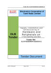
Basic System
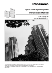
Basic System consists of one Shelf called Basic Shelf and it can be equipped with up to 192
lines (including Extensions and CO lines).
DIGI
TA
L SU
PE
R HY
BR
ID
PO
FU
SY
ST
EM
RU
N
WE
R
SE
ON
OF
OF
F LIN
E
AL
AR
M
1
F
Basic Shelf
A Basic Shelf is always required. It contains its own power supply and 14 mounting spaces
called "Slots." The Basic Slot 1 (BS1) is provided for installing the CPU card. The TSW card
is already installed in the Basic Slot 2 (BS2) at the factory. The remaining 12 slots provide
mounting space for various cards that can be used. Any optional service card can be mounted
in any one of these 12 slots. So these slots are called "Free Slot (FS)."
Construction of Basic Shelf
P
O
W
E
R
22
F F F F F F F F F F F F B B
S S S S S S S S S S S S S S
1 2 3 4 5 6 7 8 9 10 11 12 1 2
Installation Manual
System Outline
1.2.2
System Expansion
Building Block System
The KX-TD500 system can consist of one, two, or three shelves (Basic and Expansion 1,2).
Each shelf contains its own power supply.
Expansion Shelf
An optional Expansion Shelf consists of its own power supply and 14 Free Slots for mounting
any optional cards. It can be equipped with up to 224 lines (including Extensions and CO
lines).
Construction of Expansion Shelf (1 and 2)
P
O
W
E
R
Installation Manual
F F F F F F F F F F F F F F
S S S S S S S S S S S S S S
1 2 3 4 5 6 7 8 9 10 11 12 13 14
23
System Outline
System Expansion
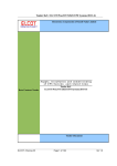
The KX-TD500 system's capacity can be expanded by installing up to two Expansion Shelves
on the Basic Shelf.
Fully expanded system (Basic Shelf + Expansion Shelf 1 + Expansion Shelf 2) is called "3Shelf System."
3-Shelf System
DIGI
TA
L SU
PE
R HY
BR
ID
SY
ST
EM
RU
N
OF
F LIN
E
AL
AR
M
24
Installation Manual
System Outline
1.2.3
System Capacity
The KX-TD500 system can be equipped with up to 512 ports, if expanded to a 3-Shelf System.
A Max.192 of CO lines and 448 extensions are available and the total of them should be less
than 512 ports.
Note
• You cannot assign any cards which exceed the system capacity.
When the system starts up with excess cards by the automatic configuration mode, they will
be ignored.
Please refer to Section "2.10.2 CPU Rotary-Switch Features" for further information.
Port Limit of Extension/CO Lines
Maximum number of Extensions (PT/SLT) and CO lines allowable per system/shelf is as
shown below.
Item
Maximum Port Number
System
Basic Shelf
Expansion Shelf
512
192
224
2 PT Extension +
SLT Extension
448
192
192
3 PT Extension
384
128
128
4 SLT Extension
448
160
160
5 ISDN Extension
96
-
-
6 CO Line
192
192
192
1 PT Extension +
SLT Extension +
CO Line
Installation Manual
25
System Outline
Port Limit of Other Terminals
Maximum number of other terminals allowable per system is as shown below.
Maximum Port Number
Item
System
1
Doorphone
8
2
DSS Console
64
3
VPS (DPT)
48
Notes
• There is a limit of 16 VPS (DPT) ports per shelf.
• VPS (DPT) can be connected to 8 units per system.
• A DSS Console is counted as a PT extension.
Port/Resource Number per Card
Maximum number of Ports/Resources per Extension/CO card is as follows:
Number of Port
Model Number
26
Card Name
CO Line
Extension
SLT
PT
Others
KX-T96161
DPH
-
-
-
4
KX-T96170
HLC
-
8*1
8*1
-
KX-T96172
PLC
-
-
8
-
KX-T96174
SLC
-
8
-
-
KX-T96175
SLC-M
-
8
-
-
KX-T96180
LCOT
8
-
-
-
KX-T96181
GCOT
8
-
-
-
KX-T96182
DID
4
-
-
-
KX-T96185
OPX
-
4
-
-
KX-T96187
T1
24
(24)*2
-
-
KX-TD50170
DHLC
-
8*3
8
-
KX-TD50172
DLC
-
-
16
-
KX-TD50175
ESLC
-
16
-
-
KX-TD50180
ELCOT
8
-
-
-
KX-TD50288
BRI
16*4
-
-
-
Installation Manual
System Outline
Number of Port
Model Number
KX-TD50290
*1
*2
*3
*4
*5
Card Name
CO Line
PRI23
23*5
Extension
SLT
PT
-
-
Others
-
SLTs and PTs are 8 units altogether.
Counted as an SLT resource, when channel type is set to "OPX."
An XDP-SLT cannot be used when the port is assigned to the DSS console.
8 BRI Ports
1 PRI Port
Card Limit
Maximum number of special cards allowable per system/shelf is as shown below.
Maximum Card Number
Item
System
Basic
Shelf
Expansion
Shelf
1 DISA Card
8
-
-
2 AGC Card
8
-
-
3 RMT or ERMT
Card
1
-
-
4 T1 Card
8
3
3
5 DPH Card
2
-
-
6 PRI23 Card
8
6
7
Notes
• A T1 Card should be installed in Free Slot 01, 05, or 09.
• A PRI23 Card should be installed in Free Slot 01, 03, 05, 07, 09, 11 or 13.
Installation Manual
27
System Outline
1.3
System Connection Diagram
1.3.1
System Connection Diagram
Central Office Lines
DIGIT
AL
SUPE
R HYBR
ID
SYST
EM
RUN
OFF
LINE
ALAR
M
Panasonic
Doorphone 1
Panasonic
Panasonic
Panasonic
Doorphone 2 Doorphone 3
Doorphone 4
(two pair)
DIGI
TAL
Panaso
nic
(two pair)
KX-TD500 System
Off Premise Extension Power
Unit KX-T96186
KX-T7220
KX-T7235
(two pair)
(one pair)
(two pair)
DIGITAL
Panasonic
Panasonic
(two pair)
Single Line Telephone
(one pair)
KX-T70XX
KX-T7250
(three pair)
KX-T7230
(two pair)
(two pair)
Data Terminal
19
20
21
13
22
14
23
15
7
24
16
8
17
9
1
18
10
2
11
3
12
4
5
6
(one pair)
KX-T7130
XXX
XXXXXXXXX
TALK
ON
OFF
AB
C
2
JK
L
5
TU
V
8
3
DE
F
MN
O
1
I
GH
S
6
4
WX
PR
Y
Pan
aso
nic
9
DP
ER
0
(two pair)
REDIAL/
PAUSE
(two pair)
XXXX
PROGRAM
AUTO
XXXXXXX
SOUND
MUTE
XXXXXXXXX
XXXX
XXXXXXXXXXXXXXXXXX
KX-T7040
KX-T7433
7
TONE
1
2
3
CH
LOW
10CH
4
5
6
7
8
O
AUT
9
CHARG
ER
XX
10
HOLD
FULL
N
SCA
MUTE
VOLUME
MIC
DIG
ITA
L
CHARGE
Cordless Phone
XXXXXXXXX
nic
aso
Pan
XXXXXXXXX
XX
XX
PAGE/INTER
COM
Pana
sonic
(two pair)
19
20
21
13
22
14
23
15
7
24
16
8
17
9
1
18
10
2
11
3
12
4
5
6
(one pair)
KX-T7436
KX-T7425
KX-T7240
(two pair)
(two pair)
(two pair)
Telephone Answering
Machine with Facsimile
TVS200
VOICE PROCESS
ING SYSTEM
KX-TVS200
(one pair)
KX-T7420
KX-T7440
KX-T7431
(two pair)
(four pair)
11
22
33
10
44
21
55
32
9
54
31
53
30
64
41
52
29
63
40
51
28
5
62
39
16
50
27
4
61
38
15
Voice Processing
System
65
42
19
18
17
Panasonic
66
43
20
8
7
6
49
26
60
37
ANSW
ER
48
59
RELE
ASE
ISDN Telephone
KX-T7441
Parallel connections of extension is available. Please refer to "Paralleled Telephone"
of Section 1.3 "System Features" in the Features Guide for further information.
28
Installation Manual
System Outline
DID
KX-T96182
DLC
DIG
ITAL
Pan
aso
nic
11
22
33
10
44
21
55
32
9
54
31
65
42
19
53
30
64
41
18
52
29
63
40
17
51
28
62
39
16
50
27
4
KX-TD50172
66
43
20
8
7
6
5
61
38
15
49
26
60
37
48
ANSWER
59
RELEASE
CO DID LINE
KX-T72XX
CO LINE
KX-T74XX
LCOT
KX-T96180
KX-T7440
KX-T7441
KX-T7240 KX-T7040
DIGIT
AL
Pan
ason
ic
11
22
33
10
44
21
55
32
9
66
43
20
54
31
8
65
42
19
53
30
7
64
41
18
52
29
6
63
40
17
51
28
5
62
39
16
50
27
4
61
38
15
49
26
60
37
48
ANSWER
59
RELEASE
ELCOT
KX-TD50180
C.O.
CO LINE
DHLC
KX-T72XX
KX-T74XX KX-T7441 KX-T7440 KX-T7240
KX-T70XX
KX-T7130
KX-TD50170
XXXXXXXXXXXX
GCOT
KX-T96181
S
2
L
5
V
DE
F
MN
O
3
6
Y
Pana
sonic
9
8
7
DP
ER
0
REDIAL/
PAUSE
TONE
PROGRAM
CO OPX LINE
ISDN BRI Line
(Digital Trunk)
C
JK
4
WX
PR
Single Line
Telephone Data Terminal
KX-T7040
OPX PWR
UNIT
KX-T96186
AB
TU
1
I
GH
AUTO
MUTE
1
2
3
4
5
6
7
8
9
10
CH
sonic
Pana
Telephone Answering
System with Facsimile
Cordless Phone
DIG
ITAL
Pan
aso
nic
OPX
KX-T96185
HLC
BRI
KX-TD50288
KX-T7240
KX-T7130
KX-T70XX
KX-T7040
KX-T96170
XXXXXXXXXXXX
AB
C
2
JK
L
5
TU
V
DE
F
MN
O
3
1
I
GH
S
6
4
WX
PR
Y
Pana
sonic
9
8
7
DP
ER
0
REDIAL/
PRI23
ISDN PRI Line KX-TD50290
(Digital Trunk)
C.O.
T-1
Line
T1 Line
(Digital Trunk)
T1
KX-T96187
PAUSE
TONE
PROGRAM
AUTO
MUTE
Single Line
Telephone
9
10
Telephone Answering
Cordless Phone System with Facsimile
1
2
3
4
5
6
7
8
CH
sonic
Pana
Data Terminal
DIG
ITAL
Pan
aso
nic
PLC
KX-T96172
SLC
KX-T96174
/
ESLC
RMT/ERMT KX-TD50175
/
KX-T96196/
SLC-M
KX-TD50197
KX-T96175
AGC
KX-T7240
KX-T7130
KX-T70XX
KX-T7040
DISA
KX-T96191
KX-T96193
BATT
24V
A46
POWER
DPH
X
XXXXXXXXXXX
GH
I
1
PR
S
4
AB
C
2
JK
L
5
TU
V
DE
F
MN
O
WX
TONE
3
6
Y
Pan
ason
ic
9
8
7
DP
1
2
3
ER
4
0
5
6
7
8
9
10
SCAN
CH
AUTO
sonic
Pana
Single Line Data Terminal
Telephone
Cordless Phone
10CH
Telephone Answering
System with Facsimile
KX-T96161
UNIT
SMDR
Panasonic
TSW-CONF
Panasonic
Doorphone 1
Doorphone 2
Panasonic
Doorphone 3
Panasonic
Doorphone 4
Amplifier
Digital OHCA
PC
Paging Speaker 1
Amplifier
Paging Speaker 2
Radio
Installation Manual
Radio
29
System Outline
Paging Speaker 1
Amplifier
DIG
ITA
L SUP
ER
HYB
RID
SYS
TEM
RUN
OFF
LIN
E
ALA
RM
Paging Speaker 2
Amplifier
Radio
Printer
Radio
To AC Outlet
Personal Computer (PC)
30
Installation Manual
System Outline
1.4
Service Cards Description
1.4.1
Extension Cards
Hybrid Line Circuit (HLC) Card (KX-T96170);
This card interfaces Analog Proprietary Telephones (APTs)/Single Line Telephones (SLTs)/
DSS Consoles and the TDM (Time Division Method) bus. It provides 8 APTs/SLTs/DSS
Consoles to the system per HLC card.
Proprietary Line Circuit (PLC) Card (KX-T96172);
This card interfaces Analog Proprietary Telephones (APTs)/DSS Consoles and the TDM bus.
It provides 8 APTs/DSS Consoles to the system per PLC card.
Single Line Telephone Circuit (SLC) Card (KX-T96174);
This card interfaces Single Line Telephones (SLTs) and the TDM bus. It provides 8 SLTs to
the system per SLC card.
SLC with Message Waiting (SLC-M) Card (KX-T96175);
This card is the same as the standard SLC card and except that it has the capability to turn on/
off the message waiting lamp of an SLT.
Off Premise Extension (OPX) Card (KX-T96185);
This card interfaces 4 off premise extensions through off premise extension power unit.
Digital Hybrid Line Circuit (DHLC) Card (KX-TD50170);
This card interfaces Digital Proprietary Telephones (DPTs)/Analog Proprietary Telephones
(APTs)/Single Line Telephones (SLTs)/DSS Consoles and the TDM bus. It provides 8 DPTs/
APTs/SLTs/DSS Consoles to the system per DHLC card.
Digital Proprietary Line Circuit (DLC) Card (KX-TD50172);
This card interfaces Digital Proprietary Telephones (DPTs)/DSS Consoles and the TDM bus.
It provides 16 DPTs/DSS Consoles to the system per DLC card.
Installation Manual
31
System Outline
Enlarged Single Line Telephone Circuit with Message Waiting (ESLC) Card (KXTD50175);
This card interfaces Single Line Telephones (SLTs) and the TDM bus. It provides 16 SLTs to
the system per ESLC card. It has the capability to turn on/off the message waiting lamp of an
SLT.
32
Installation Manual
System Outline
1.4.2
CO Trunk Cards
Loop Start Central Office Trunk (LCOT) Card (KX-T96180);
This card interfaces 8 central office loop start trunks and the TDM bus. It provides 8 CO lines
to the system per LCOT card. With loop start, a line is seized by bridging through a resistance
between the tip and ring (both wires) of the telephone line.
Ground Start Central Office Trunk (GCOT) Card (KX-T96181);
This card interfaces 8 central office trunks and the TDM bus. It provides 8 CO lines to the
system per GCOT card.
This card uses a way of signaling on subscriber trunks in which one side of the two wire trunk
(typically the "Ring" conductor of the Tip and Ring) is momentarily grounded to get a dial
tone.
Note
• There are two types of switched trunks one can typically lease from a local phone
company — Loop Start and Ground Start.
You must be careful to order the correct type of trunk from your local phone company
and correctly install your telephone system at your end — so that they both match.
Direct Inward Dialing Trunk (DID) Card (KX-T96182);
This card interfaces 4 central office trunks arranged for Direct Inward Dialing (DID) and the
TDM bus.
T1 Digital Trunk Card (KX-T96187);
This card interfaces 1 T1 line and the TDM bus. It is available to connect a T1 line to the system
per T1 card. A T1 line has a capacity of 24 voice conversations.
Enhanced Loop Start Central Office Trunk (ELCOT) Card (KX-TD50180);
This card interfaces 8 central office loop start trunks and the TDM bus. It provides 8 CO lines
to the system per ELCOT card. With loop start, a line is seized by bridging through a resistance
between the tip and ring (both wires) of the telephone line. This card supports Caller ID
service.
ISDN Basic Rate Access Interface (BRI) Card (KX-TD50288);
This card interfaces ISDN Basic Access line (2B+D). It is available to connect 8 BRI-ISDN
lines to the system per BRI-ISDN card. A BRI-ISDN line has capacity of 2 voice
conversations.
Installation Manual
33
System Outline
ISDN Primary Rate Access Interface (PRI23) Card (KX-TD50290);
This card interfaces ISDN Primary Access line. (1 circuit/card)
A PRI-ISDN line has capacity of 23 voice conversations.
34
Installation Manual
System Outline
1.4.3
Resource Cards
Direct Inward System Access (DISA) Card (KX-T96191);
This card interfaces 4 central office trunks arranged for Direct Inward System Access (DISA)
and the TDM bus.
Automatic Gain Control (AGC) Card (KX-T96193);
This card is used to maintain volume of CO-to-CO communication. An electronic circuit which
compares the level of an incoming signal with a previously defined standard and automatically
amplifies or attenuates that signal so it arrives at its destination at the correct level.
Remote Circuit (RMT) Card (KX-T96196);
This card is necessary for accessing the system from a remote location. This card supports baud
rate at 1,200 bps.
Enhanced Remote Circuit (ERMT) Card (KX-TD50197);
This card is necessary for accessing the system from a remote location. This card supports the
V.34 modem standard of ITU-T recommendation. This card supports data transmission rate at
33,600 bps.
Installation Manual
35
System Outline
1.4.4
Other Cards
Off-Hook Call Announcement (OHCA) Card (KX-T96136);
This card is for Off-Hook Call Announcement feature and is installed on the HLC or PLC card.
Doorphone Circuit (DPH) Card (KX-T96161);
This card interfaces 4 doorphones and the TDM bus. Up to 4 doorphones per DPH card can be
connected to the system.
Caller ID Card (KX-TD193);
This card supports the Caller ID service provided by Central Office, and is installed on the
ELCOT card.
Caller ID allows the extension user to see the name or phone number of an external caller on
the display before answering the call.
TSW Conference Expansion Card (TSW-CONF) Card (KX-TD50104);
This card provides 64 additional conference trunks, and is installed on the TSW card.
Off-Hook Call Announcement for Digital Telephone (DOHCA) Card (KX-TD50105);
This card is for Off-Hook Call Announcement features on DPT, and is installed on the TSW
card. This card is required to utilize "DPT Integration" feature. (Please refer to "Integration,
DPT" in Section "1.3 System Features" of the Features Guide.)
36
Installation Manual
System Outline
1.5
Proprietary Telephones
1.5.1
Proprietary Telephones
The following Panasonic Proprietary Telephones are available with this system.
Model
Type
Hands-free
mode
Display
CO
PF/F
Soft
KX-T7020
KX-T7030
KX-T7050
KX-T7055
APT
APT
APT
APT
SP-PHONE
SP-PHONE
MONITOR
MONITOR
—
1-Line
—
—
12
12
12
3
4 (PF)
4 (PF)
4 (PF)
3 (PF)
—
—
—
—
KX-T7130
APT
SP-PHONE
1-Line
12
12 (PF)
—
KX-T7220
KX-T7230
KX-T7235
KX-T7250
DPT
DPT
DPT
DPT
SP-PHONE
SP-PHONE
SP-PHONE
MONITOR
—
2-Line
6-Line
—
24
24
12
6
—
—
10 (F)
—
—
3
3
—
KX-T7420
KX-T7425
KX-T7431
KX-T7433
KX-T7436
KX-T7450
DPT
DPT
DPT
DPT
DPT
DPT
SP-PHONE
SP-PHONE
SP-PHONE
SP-PHONE
SP-PHONE
MONITOR
—
—
1-Line
3-Line
6-Line
—
12
24
12
24
24
12
—
—
—
—
10 (F)
—
—
—
—
3
3
—
Notes
• APT: Analog Proprietary Telephone
• DPT: Digital Proprietary Telephone
• SP-PHONE: Used for a hands-free speakerphone operation.
• MONITOR: Used for a hands-free dialing operation.
• CO: CO line access button
• PF: Programmable Feature button
• F: Function button
Used to perform the corresponding displayed function or operation.
• Soft: Soft button
Used to perform the function or operation that appears on the bottom line of the
display.
Installation Manual
37
System Outline
1.6
Specifications
1.6.1
General Description
System Capacity
CO lines
192 max.
Stations
448 max.
Control Method
CPU
32-bit CPU with 16-bit Data Bus
Switching
Non Blocking PCM Time Switch
Power Supplies
Primary
120 V AC, 60 Hz
Secondary
Station Supply Volt: 30 V
Circuit Volt: 5 V, 15 V
Power Failure
• Memory backup duration: seven years with a factory-provided lithium battery
• Power Failure Transfer function is provided.
• System operation for about four hours using recommended batteries (consisting of two
12 V DC 40 Ah Automobile-type batteries)
Dialing
Outward/Internal
Dial Pulse (DP) 10 pps, 20 pps
Tone (DTMF) Dialing
Mode Conversion
DP-DTMF, DTMF-DP
38
Installation Manual
System Outline
Connector
CO lines
Amphenol Connector
ISDN lines
Modular Jack (RJ45)
Stations
Amphenol Connector
Paging Output
Pin Jack (RCA JACK)
External Music Input
Two-conductors Jack
(MINIJACK 3.5 mm (9/64 inch) in diameter)
Extension Connection Cable
Telephones
Cable
Single Line Telephones
1-pair wire (T, R)
KX-T7420, KX-T7425, KX-T7431, KX-T7433,
KX-T7436, KX-T7450, KX-T7220, KX-T7230,
KX-T7235, KX-T7250
1-pair wire (D1, D2) or
2-pair wire (T, R, D1, D2)
KX-T7020, KX-T7030, KX-T7050, KX-T7055
2-pair wire (T, R, D1, D2)
KX-T7440, KX-T7441, KX-T7240, KX-T7040
1-pair wire (D1, D2) or
2-pair wire (T, R, D1, D2)
KX-T7130
3-pair wire (T, R, D1, D2, P1, P2)
SMDR (Station Message Detail Recording)
Interface
RS-232C
Output Equipment
Printer/Personal Computer
Detail Recording
Date, Time, Extension Number, CO Line Number, Dialed Number, Ring Duration,
Call Duration, Account Code, Caller ID, Timed Reminder
Installation Manual
39
System Outline
1.6.2
Characteristics
Station Loop Limit
Analog, Digital Proprietary Telephone
40 ohms
Single Line Telephone
600 ohms including set
Doorphone
20 ohms
Minimum Leakage Resistance
15,000 ohms
Maximum Number of Station Instruments per Line
1 for Analog, Digital Proprietary Telephone, or Single Line Telephone
2 by Parallel or eXtra Device Port Connection of a Proprietary Telephone and a Single Line
Telephone
Ring Voltage
75 Vrms at 25 Hz depending on the Ringing Load
Primary Power
120 V AC, 60 Hz, 12 A max.
Central Office Loop Limit
1,600 ohms max.
Environmental Requirements
Temperature range: 0 °C – 40 °C (32 °F – 104 °F)
Rel. Humidity: 10 % – 90 % (no condensation)
Switchhook Flash Timing Range
204 – 1,000 milliseconds
40
Installation Manual
System Outline
Power Unit Functions
1. Power supply (+5.9 V DC, 15 V DC, GND) for a shelf.
2. Power failure detection.
A circuit in power unit detects power failures of +5.9 V DC, 15 V DC, AC Voltage, and
3 power alarm signals are sent to CPU card as DC alarm, AC alarm and Heat alarm.
3. Generation of bell signal. (25 Hz, 75 Vrms)
CPU (KX-TD50101) Card Functions
1. Call process and basic shelf main protocol (Microprocessor 80386EX).
Time switch (TSW) control, detection of system clock alarm, basic shelf power down and
expansion shelf power down alarm, watchdog timer overflow.
2. System switch interface.
There are Operation Switch (MODE) (10 modes, 0 to 9) and System Switch (SYSTEM) (10
modes, 0 to 9) on the CPU rotary switch.
3. Terminal interface.
CPU card has two RS-232C terminal interfaces.
CPU (KX-TD50101) Card Operation
1. Operation Switch (MODE) and System Switch (SYSTEM) are set by turning with
screwdriver.
2. Reset switch is non-lock push switch.
3. LED for battery alarm lights when voltage of Lithium-battery becomes too low (less than
2.5 V).
4. LED for watchdog lights when the software is running away.
TSW Card Functions
1. Time switch.
Capability of switching voice is 768ch
768ch.
2. Generation of call progress tones.
Call progress tones are dial tone, busy tone, reorder tone and ringback tone.
3. Conference circuit.
TSW card has 3-party 8 conference's circuits.
For CO-to-CO speech amplifier AGC card can be inserted to a free slot of basic or
expansion shelf.
4. Paging interface.
TSW card has 2 pre-amplifier circuits for paging. In order to adjust volume, each amplifier
circuit is equipped with a knob.
5. Music-in interface.
TSW card has 2 interface circuits for music on hold or BGM.
Installation Manual
41
System Outline
TSW Card Operation
1. A knob for adjusting volume of external paging is turned with a screwdriver from front of
TSW card.
HLC Card (KX-T96170) Functions
Hybrid Line Circuit card is for APT, DSS Console and SLT. (8 extensions/card)
1. Standard SLT interface. SLT interface is quite the same as that of SLC card.
2. APT and DSS Console interface. APT and DSS Console interface is quite the same as that
of PLC card.
Note
• DSS Consoles KX-T7440 and KX-T7441 can be connected to this card.
In this case, however, ANSWER and RELEASE buttons on the KX-T7441 do not
function.
3. Interface for OHCA feature with APT (KX-T7130).
This is quite the same as that of PLC.
4. Power Failure Transfer by each port. (when using SLT)
Power Failure Transfer is quite the same as that of SLC card.
5. Diagnostic Transfer by each port. Diagnostic Transfer is quite the same as that of SLC card.
HLC Card (KX-T96170) Operation
LED indicator on the HLC card lights when the system reset or HLC local reset occurs.
PLC Card (KX-T96172) Functions
Proprietary Line Circuit card (8 APT extensions/card)
1. APT and DSS Console interface. (8 circuits/card)
Maximum loop resistance: 40 ohms
Power supply 1: +30 V (supplied through speech path, and with current limitation circuit).
Power supply 2: +15 V (supplied through the data line).
Note
• DSS Consoles KX-T7440 and KX-T7441 can be connected to this card.
In this case, however, ANSWER and RELEASE buttons on the KX-T7441 do not
function.
2. Interface for OHCA feature with APT (KX-T7130).
When an APT with OHCA feature is connected to a port, an OHCA piggyback card (KXT96136) should be mounted on its interface circuit.
PLC Card (KX-T96172) Operation
The LED indicator on the PLC card lights when the system reset or PLC local reset occurs.
42
Installation Manual
System Outline
SLC Card (KX-T96174) Functions
Single Line Telephone Circuit card
1. Standard SLT interface.
Maximum loop resistance: 600 ohms. (including SLT)
Power supply: +30 V (with current limitation circuit.)
2 DTMF receivers, dial pulse detector.
2. Power Failure Transfer (PFT) by each port.
When a power failure occurs, SLT Tip/Ring are led by a PFT relay, but SLT PFT modular
and ELCOT/LCOT/GCOT modular should be connected to each other in advance.
3. Diagnostic Transfer (DT) by each port.
Diagnostic relay is placed in Tip/Ring of each port. During diagnostic test, only one
diagnostic relay in the SLT of a system is activated.
SLC Card (KX-T96174) Operation
The LED indicator on the SLC card lights when system reset or SLC local reset occurs.
SLC-M Card (KX-T96175) Functions
Single Line Telephone Circuit with Message Waiting card
1.
2.
3.
4.
Same as SLC card.
Same as SLC card.
Same as SLC card.
SLT with Message Waiting Lamp interface
Power supply to Message Waiting
Lamp: +80 V DC (when 1mA)
SLC-M Card (KX-T96175) Operation
Same as SLC card
OPX Card (KX-T96185) Functions
Off Premise Extension (4 OPX Lines/card)
OPX Power Unit is necessary.
OPX Power Unit should be connected with OPX card, and Single Line Telephones for OPX
should be connected with OPX card.
Installation Manual
43
System Outline
DHLC Card (KX-TD50170) *1Functions
1. Standard SLT interface.
Power supply: +30 V (with current limitation circuit).
2 DTMF receivers, dial pulse detector.
2. Interface for APT, DPT, DSS Console and VPS (DPT).
The interface for the APT, DPT, DSS Console and VPS (DPT) is similar to the DLC card.
3. Interface for OHCA feature with APT (KX-T7130).
The OHCA feature with APT (KX-T7130) is available without any optional cards.
4. Interface for OHCA feature with DPTs (KX-T7235, KX-T7436).
The interface for OHCA feature with DPTs (KX-T7235, KX-T7436) is similar to the DLC
card.
5. Interface for power failure transfer by each port (when using SLT).
When a power failure occurs, SLT Tip/Ring are led by a PFT relay, but SLT PFT modular
and LCOT/GCOT/ELCOT modular should be connected to each other in advance.
6. Interface for Diagnostic Transfer by each port.
Diagnostic relay is placed in Tip/Ring of each port. During diagnostic test, only one
diagnostic relay in the SLT of a system is activated.
7. There is a limit of 8 VPS (DPT) ports per card.
DHLC Card (KX-TD50170) Operation
1. The LED indicator on the DHLC card lights when the system reset or DHLC local reset
occurs.
DLC Card (KX-TD50172) Functions
1. Interface for DPT, DSS Console and VPS (DPT) (16 circuits/card).
Maximum loop resistance: 40 ohms
Power supply: +15 V (supplied through the data line)
2. Interface for OHCA feature with DPTs (KX-T7235, KX-T7436).
When a DPT with OHCA feature is connected to a port, a DOHCA card should be mounted
on the TSW card.
3. There is a limit of 8 VPS (DPT) ports per card.
DLC Card (KX-TD50172) Operation
1. The LED indicator on the DLC card lights when the system reset or DLC local reset occurs.
*1
For a DPT, APT, DSS Console, VPS (DPT) and SLT. (8 extensions or 16 extensions with XDP/card. Please refer to Section
"2.4.13 Extra Device Port (XDP) Connection" for XDP.)
44
Installation Manual
System Outline
ESLC Card (KX-TD50175) Functions
Enlarged Single Line Telephone Circuit with Message Waiting card (16 extensions/card)
1. Standard SLT interface.
Power supply: +30 V (with current limitation circuit)
4 DTMF receivers, and dial pulse detectors.
2. Interface for power failure transfer by ports 1 to 8.
When a power failure occurs, SLT Tip/Ring are led by a PFT relay, but SLT PFT modular
and LCOT/GCOT/ELCOT modular should be connected to each other in advance.
ESLC Card (KX-TD50175) Operation
1. The LED indicator on the ESLC card lights when the system reset or ESLC local reset
occurs.
LCOT Card (KX-T96180) Functions
Loop Start Central Office Trunk card (8 CO Lines/card)
1. Loop start CO interface.
CPC detection, 1 DTMF generator.
With loop start, you seize a line by bridging through a resistance between the tip and ring
(both wires) of your telephone line.
2. Power Failure Transfer (PFT) by each port
Tip/Ring of CO are connected to a CO interface circuit, and directly to LCOT PFT modular.
When power failure occurs, CO Tip/Ring leads are directly connected to SLT Tip/Ring
leads, but LCOT PFT modular and SLT PFT modular should be connected to each other in
advance.
3. Diagnostic Transfer (DT) by each port.
A diagnostic relay is placed in Tip/Ring of each port.
During diagnostic test, only one diagnostic relay in an LCOT of a system is activated.
LCOT Card (KX-T96180) Operation
The LED indicator on the LCOT card lights when the system reset or LCOT local reset occurs.
Installation Manual
45
System Outline
GCOT Card (KX-T96181) Functions
Ground Start Central Office Trunk card (8 CO Lines/card)
1. Ground start CO interface.
CPC detection, 1 DTMF generator.
A way of signaling on subscriber trunks in which one side of the two wire trunk (typically
the "Ring" conductor of the Tip and Ring) is momentarily grounded to get dial tone.
2. Power Failure Transfer (PFT) by each port.
Tip/Ring of CO are connected to a CO interface circuit, and directly to GCOT PFT modular.
When power failure occurs, CO Tip/Ring leads are directly connected to SLT Tip/Ring
leads, but GCOT PFT modular and SLT PFT modular should be connected each other with
connection cords in advance.
3. Diagnostic Transfer (DT) by each port.
A diagnostic relay is placed in Tip/Ring of each port. During diagnostic test, only one
diagnostic relay in a GCOT of a system is activated.
GCOT Card (KX-T96181) Operation
The LED indicator on the GCOT card lights when the system reset or GCOT local reset occurs.
DID Card (KX-T96182) Functions
Direct Inward Dialing card
Wink start/immediate start DID interface.
(4 circuits/card)
45 V used in circuits is originated from DC-DC converter on DID card.
The DID card will receive pulse signals only.
DID Card (KX-T96182) Operation
The LED indicator on the DID card lights when the system reset or DID local reset occurs.
T1 Digital Trunk Card (KX-T96187) Functions
T1 interface. (1 circuit/card)
T1 is a digital transmission link with a capacity of 1.544 Mbps.
T1 can carry 24 voice conversations.
Frame Format :
D4/ESF
Line Coding
AMI/B8ZS
:
Channel Type :
LCO/GCO/DID/OPX/TIE (E&M)
Signaling
Pulse/DTMF
:
(DTMF: 24 receivers and 6 generators)
46
Installation Manual
System Outline
T1 Digital Trunk Card (KX-T96187) Operation
The LED indicator on T1 card lights when the system reset, or T1 card local reset or T1 line
fault occurs.
ELCOT Card (KX-TD50180) Functions
Enlarged Loop Start Central Office Trunk card (8 CO Lines/card)
1. Loop start CO interface.
1 DTMF generator. Line Reversal detection.
With loop start, you seize a line by bridging through a resistance between the tip and ring
(both wires) of your telephone line.
2. Caller ID Capability.
Two Caller ID Cards (KX-TD193) can be mounted on ELCOT card.
3. Power Failure Transfer (PFT) by each port.
Tip/Ring of CO are connected to a CO interface circuit, and directly to ELCOT PFT
modular. When power failure occurs, CO Tip/Ring leads are directly connected to SLT Tip/
Ring leads, but ELCOT PFT modular and SLT PFT modular should be connected to each
other in advance.
4. Diagnostic Transfer (DT) by each port.
A diagnostic relay is placed in Tip/Ring of each port.
All diagnostic relays are set to the diagnostic position except on the call.
ELCOT Card (KX-TD50180) Operation
1. The LED indicator on the ELCOT card lights when the system reset or ELCOT local reset
occurs.
BRI Card (KX-TD50288) Functions
ISDN Basic Rate Access Interface. (8 circuits/card)
a) 8 ISDN Basic Interface (2B+D)
b) S0/EXT flexibility for each line
c) Power Feeding of EXT mode
One card total: 18 W max.
One Line: 4.5 W max.
The maximum power consumption available for each line is 4.5 W, however, the whole
power consumption available for the card (8 lines in total) is limited to less than 18 W.
(e.g., If 2 lines consume 4.5 W each, the rest of 6 lines can consume 1.5 W each.)
d) Impedance: 100 ohms
BRI Card (KX-TD50288) Operation
1. The LED indicator on the BRI card lights when the system reset, BRI card local reset or
BRI card fault occurs.
2. The DC Alarm LED indicator on the BRI Card lights if Power feeding of EXT mode
exceeds the limit described in c) in BRI Card (KX-TD50288) Functions.
Installation Manual
47
System Outline
[LED Indication Table for BRI Card (KX-TD50288)]
LED No. (Item)
D50 (DC ALM)
D20
Color
Red
Red
Status
Contents
ON
DC Alarm
OFF
Normal
ON
Card Fault
OFF
Normal
• When the 1st bit of the DIP Switch (SW2) is set to "ON"
LED No. (Item)
Color
Status
Contents
D21–D27
Green
-
Not used
D28
Green
FLASH
Clock Master at External Clock Mode
ON
Detection of Signal
OFF
No Detection of Signal
• When the 1st bit of the DIP Switch (SW2) is set to "OFF"
LED No. (Item)
D21
D22
D23
D24
48
Color
Green
Green
Green
Green
Status
Contents
ON
LINE1 Data Link established
FLASH
LINE1 Layer1 Synchronization established
(Detection of Signal)
OFF
LINE1 No Detection of Signal
ON
LINE2 Data Link established
FLASH
LINE2 Layer1 Synchronization established
(Detection of Signal)
OFF
LINE2 No Detection of Signal
ON
LINE3 Data Link established
FLASH
LINE3 Layer1 Synchronization established
(Detection of Signal)
OFF
LINE3 No Detection of Signal
ON
LINE4 Data Link established
FLASH
LINE4 Layer1 Synchronization established
(Detection of Signal)
OFF
LINE4 No Detection of Signal
Installation Manual
System Outline
• When the 1st bit of the DIP Switch (SW2) is set to "OFF"
LED No. (Item)
D25
Color
Green
D26
Green
D27
Green
D28
Green
Status
Contents
ON
LINE5 Data Link established
FLASH
LINE5 Layer1 Synchronization established
(Detection of Signal)
OFF
LINE5 No Detection of Signal
ON
LINE6 Data Link established
FLASH
LINE6 Layer1 Synchronization established
(Detection of Signal)
OFF
LINE6 No Detection of Signal
ON
LINE7 Data Link established
FLASH
LINE7 Layer1 Synchronization established
(Detection of Signal)
OFF
LINE7 No Detection of Signal
ON
LINE8 Data Link established
FLASH
LINE8 Layer1 Synchronization established
(Detection of Signal)
OFF
LINE8 No Detection of Signal
PRI23 Card (KX-TD50290) Functions
ISDN Primary Rate Access Interface-1.544 MHz. (1 circuit/card)
a) PRI23 carry 23 voice conversations
b) Frame Format: CRC-Multiframe
c) Line Coding: B8ZS, AMI
d) Frame Sequence
1) 4-Frame Multiframe (F4)
2) 12-Frame Multiframe (F12)
3) Extended Superframe (ESF)
4) Remote Switch (F72, SLC96)
e) Impedance: 100 ohms
Installation Manual
49
System Outline
PRI23 Card (KX-TD50290) Operation
LED indicator on the PRI23 card lights when the system reset, PRI23 card local reset or PRI23
card fault occurs.
[LED Indication Table for PRI23 Card (KX-TD50290)]
LED No. (Item)
D19 (FALT)
D20 (SYNC
ERROR)
D21 (RAI)
D22 (AIS)
D23 (SYNC)
D24 (DATA LINK)
D25–D27
50
Color
Red
Red
Red
Red
Green
Green
Red
Status
Contents
ON
Card Fault
OFF
Normal
ON
Clock Synchronization Error or Loss of Signal
(Red Alarm)
OFF
Normal
ON
Receive Remote Alarm Indication signal
(Yellow Alarm)
OFF
Normal
ON
Send Alarm Indication signal (Blue Alarm)
OFF
Normal
FLASH
Clock Master at External Clock Mode
ON
Layer1 Synchronization established (Detection
of Signal)
OFF
No Detection of Signal
ON
Data Link established
OFF
No Data Link established
-
Not used or Reserved for future use.
Installation Manual
System Outline
DISA Card (KX-T96191) Functions
1. 4 OGM trunks.
OGM duration: 30 seconds,
OGM Capacitor Backup: 5 days.
The number of OGM: 1,
Recording Algorithm: ADPCM.
2. 4 CO-to-CO speech paths without amplifier.
A CO-to-CO speech path consists of up-path and down-path.
Up-path is from call-originate CO to call-answer CO, and 1 DTMF receiver and one speech
end detector is connected to it.
Down-path is from call-answer CO to call-originate CO and one speech end detector is
connected to it.
3. Speech end detector.
Speech end detector detects call progress tones.
DISA Card (KX-T96191) Operation
1. The LED indicator on the DISA card lights when the system reset or DISA local reset
occurs.
AGC Card (KX-T96193) Functions
Automatic Gain Control card
1. 4 CO-to-CO speech paths with AGC amplifier and Echo-Suppressor.
A CO-to-CO speech path consists of up-path and down-path, up-path is from call-originate
CO to call-answer CO, and AGC amplifier is inserted and speech end detector is connected.
The Maximum amplification of AGC is 10 dB.
The Echo-Suppressor is inserted in a CO-to-CO speech path.
2. 4 DTMF receivers.
DTMF transceiver is used as DTMF repeater.
So, AGC card microprocessor controls DTMF repeater.
3. 8 Speech End Detectors.
Speech end detector of AGC is quite the same as that of the DISA card.
AGC Card (KX-T96193) Operation
The LED indicator on the AGC card lights when the system reset or AGC local reset occurs.
RMT Card (KX-T96196) Functions
Remote Circuit card
Modem (300/1200 bps) for remote administration.
RMT Card (KX-T96196) Operation
The LED indicator on the RMT card lights when the system reset or RMT local reset occurs.
Installation Manual
51
System Outline
ERMT Card (KX-TD50197) Functions
1. Modem (V.34 MODEM) for remote administration.
ERMT Card (KX-TD50197) Operation
1. The LED indicator on the ERMT card lights when the system reset or ERMT local reset
occurs.
OHCA Card (KX-T96136) Functions
OHCA (Off-Hook Call Announcement) card
This card is mounted on HLC card (KX-T96170) or PLC card (KX-T96172).
This card includes 2 OHCA circuits.
Allows an extension user to intrude through the speaker into another extension that is in
conversation using the handset.
This feature is available only for the following APT: KX-T7130.
DPH Card (KX-T96161) Functions
1. Doorphone interface (4 circuits/card).
4 doorphones can be connected using a modular connector.
2. Door opener interface (4 circuits/card).
DPH card has 4 relays for door opener. The relay opens for doorlock, closes for door
release. It also opens in the case of power failure.
Door Opener Current Limit: 24 V DC/30 V AC, 1 A max.
DPH Card (KX-T96161) Operation
1. Terminal plate on the DPH card has 8 terminals. 2 leads from door opener are directly
connected to two of 8 terminals.
Caller ID Card (KX-TD193) Functions
1. This card is mounted on ELCOT card for receiving Caller ID information sent from the
Central Office.
Four CO Lines are available for Caller ID service with one Caller ID card.
TSW-CONF Card Functions
1. This card is mounted on TSW card for conference trunk expansion.
3-party x 64 conference circuits.
DOHCA Card Functions
1. This card is mounted on TSW card for OHCA feature for DPT. OHCA feature is available
for the following DPTs: KX-T7235, KX-T7436
52
Installation Manual
System Outline
This card is required to utilize "DPT Integration" feature. (Please refer to "Integration,
DPT" of Section "1.3 System Features" in the Features Guide.)
OPX Power Unit (KX-T96186) Functions
1. Output is Ringing Signal (100 V AC, 20 Hz) and 48 V DC for OPX card.
Installation Manual
53
System Outline
54
Installation Manual
Installation
Section 2
Installation
This section describes the procedures required to
install the KX-TD500 System. Detailed instructions for
planning the installation site, installing the shelves and
optional cards, and cabling of peripheral equipment
are provided. Further information on system expansion
and peripheral equipment installation is included.
Installation Manual
55
Installation
2.1
Before Installation
2.1.1
Precautions
Please read the following notes concerning installation and connection before installing the
system.
Safety Installation Instructions
When installing telephone wiring, basic safety precautions should always be followed to
reduce the risk of fire, electric shock and injury to persons, including the following:
1. Never install telephone wiring during a lightning storm.
2. Never install telephone jacks in wet locations unless the jack is specifically designed for wet
locations.
3. Never touch uninsulated telephone wires or terminals unless the telephone line has been
disconnected at the network interface.
4. Use caution when installing or modifying telephone lines.
Installation Precautions
Avoid installing in the following places. (Doing so may result in malfunction, noise, or
discoloration.)
1. In direct sunlight and hot, cold, or humid places (Temperature range: 0 °C – 40 °C [32 °F –
104 °F]).
2. Sulfuric gases produced in areas where there are thermal springs, etc., may damage the
equipment or contacts.
3.
4.
5.
6.
Places in which shocks or vibrations are frequent or strong.
Dusty places, or places where water or oil may come into contact with the unit.
Near high-frequency generating devices such as sewing machines or electric welders.
On or near computers, telexes, or other office equipment, as well as microwave ovens or air
conditioners. (It is preferable not to install in the same room with the above equipment.)
7. Install at least 1.8 m (6 feet) from radios and televisions (both the main unit and Proprietary
Telephones).
8. Do not obstruct area around the main unit (for reasons of maintenance and inspection — be
especially careful to allow space for cooling above and at the sides of the main unit).
56
Installation Manual
Installation
Wiring Precautions
Be sure to follow these instructions when wiring the unit.
1. Do not wire the telephone cable in parallel with an AC power source, computer, telex, etc.
If the cables are run near those wires, shield the cables with metal tubing or use shielded
cables and ground the shields.
2. If cables are run on the floor, use protectors to prevent the wires from being stepped on.
Avoid wiring under carpets.
3. Avoid using the same power supply outlet for computers, telexes, and other office
equipment. Otherwise, KX-TD500's system operation may be interrupted by the induction
noise from such equipment.
4. Please use one-pair telephone wire for extension connection of (telephone) equipment such
as Single Line Telephones, data terminals, answering machines, computers, Voice
Processing Systems, etc., except Proprietary Telephones (KX-T7220, KX-T7230, KXT7235, KX-T7250 etc.).
5. The Power Switch of the system must be off during wiring. After all the wirings are
completed, turn the Power Switch on.
6. Mis-wiring may cause the system to operate improperly.
7. If an extension does not operate properly, disconnect the telephone from the extension line
and then connect again, or turn off the Power Switch of the system and then on again.
8. Use twisted pair cable for CO line connection.
9. CO lines should be installed with lightning protectors. For details, please refer to Section
"2.11.1
Lightning Protectors."
10.To assure good quality telephone connection, it is recommended new and modifications to
existing installation of customer premise wiring shall use solid twisted pair copper
conductors with minimum 24 gauge that comply with the electrical specifications for
Category 3 wiring as detailed in ANSI/EIA/TIA-570A Building Wiring Standards.
Installation Manual
57
Installation
2.1.2
Slot Construction
Expansion shelf 2
DIG
ITA
ER
HYB
RID
SYS
TEM
RU
N
OFF
LIN
PO
FU
E
ALA
WER
P F
O S
W 1
E
R
L SUP
RM
SE
ON
OF
1
F
F
S
2
F
S
3
F
S
4
F
S
5
F
S
6
F
S
7
F F F F F F F
S S S S S S S
8 9 10 11 12 13 14
Expansion shelf 1
PO
FU
P F
O S
W 1
E
R
WER
SE
ON
OF
1
F
F
S
2
F
S
3
F
S
4
F
S
5
F
S
6
F
S
7
F F F F F F F
S S S S S S S
8 9 10 11 12 13 14
F
S
4
F
S
5
F
S
6
F
S
7
F F F F F B
S S S S S S
8 9 10 11 12 1
Basic shelf
PO
FU
WER
SE
ON
OF
P F
O S
W 1
E
R
1
F
F
S
2
F
S
3
B
S
2
Basic shelf
No.
Name
Number
1
POWER - for Power Unit
1
2
BS1 (Basic Slot 1) - for CPU card
1
3
BS2 (Basic Slot 2) - for TSW card
1
4
FS1 to 12 (Free Slot 1 to 12)
- for optional service cards
12
Expansion shelf 1/Expansion shelf 2
Name
POWER - for Power Unit
FS1 to FS14 (Free Slot)
- for optional service cards
58
Number
1
14
Installation Manual
Installation
2.1.3
Guide Plate
Screws
DIG
ITA
L SU
PE
R HY
BR
ID
SY
ST
EM
RU
PO
WER
FU
SE
N
OF
F LIN
Guide Plate
E
AL
AR
M
ON
1
OFF
Fig.a
(Front Side)
Upper Guide Rail
(Rear Side)
Press
Upper Latch
(Card)
Press
Lower Latch
Card Latch
Fig.b
Lower Guide Rail
Fig.c
1. Before installing the service cards, remove the Guide Plate (See Fig.a) from the upper front
side of the basic shelf (and expansion shelf 1 and 2, if provided) by loosening the five
screws.
2. Install a service card (with facing the components side to the right) along with the upper and
lower guide rails. Press the upper and lower latch firmly until the upper latch is located
inside of the shelf. (See Fig.b and Fig.c)
Please do not touch the components side of the service card.
3. After installing the service cards, attach the Guide Plate to the upper front side of the basic
shelf (and expansion shelf 1 and 2, if provided) with five screws.
If service cards are not installed properly, the Guide Plate will not be fixed.
To remove an optional service card from the shelf:
1. Hold the upper part of the card with one hand.
2. Pull the card toward you while pushing the lower latch upward with the other hand.
3. Remove the card from the shelf when it is pulled out of the slot.
Installation Manual
59
Installation
2.1.4
Amphenol 57JE type Connector
To connect Amphenol 57JE type (screw-attach-type 50-pin connector) to the Option Card,
follow the procedure below.
1. The 50-pin connector (jack) on the Option Card has two hook-pins.
Remove the upper hook-pin, taking out the screw.
2. To attach the Amphenol 57JE type (plug) to the connector, drive the Accessory Screw at the
upper part, and fasten the Accessory Wire Tie around the lower hook-pin and the Amphenol
57JE type, as shown below.
Accessory
Screw
Option Card
50-pin
connector
Screw
Amphenol 57JE type
Hook-pin
Accessory
Wire Tie
Hook-pins
57JE type
50-pin connector
Hook-pin
Accessory
Wire Tie
When connecting a connector of the type shown
below, unscrew the lower hook-pin, too. Then drive
both Accessory Screws.
Option Card
Accessory
Screw
Amphenol
57JE type
Accessory
Screw
50-pin connector
60
Installation Manual
Installation
2.2
Installation of Shelf
2.2.1
Installation of Shelf
This subsection describes the installation of the shelf, with information on expanding the
capacity of an existing system.
Building Block System provides the enlargement of system's ability by installing the optional
Expansion Shelf.
Up to two Expansion Shelves can be installed to the system.
Each expansion shelf can be equipped with up to 224 lines (including Extensions and CO
lines).
The system can consist of one, two or three shelves (Basic, Expansion 1 and Expansion 2).
Each shelf contains its own power supply.
Installation Manual
61
Installation
2.2.2
Basic Shelf
Basic Shelf is always required and it can be equipped with up to 192 lines (including
Extensions and CO lines).
The basic shelf includes top cover and base shelf.
The following figure shows a basic system composed of a basic shelf only.
DIGI
TA
L SU
PE
R HY
BR
ID
PO
FU
SE
ON
OF
62
SY
ST
EM
RU
N
WE
R
OF
F LIN
E
AL
AR
M
1
F
Installation Manual
Installation
Basic Shelf Assembly
Top Cover
DIG
ITA
L SU
PE
R HY
BR
ID
SY
STE
M
RU
N
OF
F LIN
E
ALA
RM
1
15
2
16
5
4
3
6
7
8
9
10
11
21
12
18
PO
FU
Basic Shelf
WER
SE
ON
OF
1
F
17
19
20
Base Shelf
13
14
Installation Manual
63
Installation
1. Side Panel (Left)
2. Power Unit
3. Fuse
4. Power Indicator
5. Backup Battery Connector (Connects the Battery Adaptor Cable)
6. Power Switch (Turns ON and OFF the Power of Basic Shelf)
7. Power Supply Cable
8. Front Panel
9. Transform Cord
10. Base Side Panel (Left)
11. Power Supply Cable Connector
12. Main Power Switch (Turns ON and OFF the Power of Whole Unit)
13. Ground Wire Connector (GND)
14. Base Front Panel
15. LED Cable
16. LED Cable Connector (Connects the LED Cable)
17. Side Panel (Right)
18. Flat Cable Connector (Connects the Flat Cable from Expansion Shelf)
19. Cable Opening
20. Base Board
21. Fan Cable
64
Installation Manual
Installation
2.2.3
Expansion to 2-Shelf System
The KX-TD500 System can be expanded to 2-Shelf System by installing the Expansion Shelf
1 on the Basic Shelf.
The 2-Shelf system can be equipped with up to 416 lines (including extensions and CO lines).
The following figure shows a 2-Shelf System composed of a basic shelf and an expansion shelf.
DIGI
TA
L SU
PE
R HY
BR
ID
SY
ST
EM
RU
N
OF
F LI
NE
AL
AR
M
Installation Manual
65
Installation
Expansion Shelf Assembly
1
2
5
9
PO
FU
7
WER
SE
ON
1
OFF
10
11
8
12
4
6
3
1. Side Panel (Left)
2. Power Unit
3. Power Indicator
4. Power Switch (Turns ON and OFF the Power of Expansion Shelf)
5. Backup Battery Connector (Connects the Battery Adaptor Cable)
6. Fuse
7. Power Supply Cable
8. Front Panel
9. LED Cable Connector (Connects the LED Cable)
10. Side Panel (Right)
11. Flat Cable
12. Cable Opening
Note
• The construction of Expansion Shelf 1 and Expansion Shelf 2 is identical to each other.
66
Installation Manual
Installation
Removing the Panels <Basic Shelf>
1. Disconnect the LED cable (on the top cover) from the LED cable connector (on the basic
shelf).
Screws
Screws
DIG
ITA
L SU
PE
R HY
BR
ID
SY
ST
EM
RU
PO
FU
WER
N
OF
F LIN
E
AL
SE
ON
AR
M
1
OFF
LED cable
LED cable connector
2. Remove the top cover by loosening the four screws.
Top cover
DIG
ITA
L SU
PE
R HY
BR
ID
SY
ST
EM
RU
N
OF
F LIN
E
AL
AR
M
PO
WER
FU
SE
ON
1
OFF
Installation Manual
67
Installation
Removing the Panels <Expansion Shelf>
1. Rotate the key on the front panel counterclockwise to unlock.
2. Open the front panel toward you at right angles to the expansion shelf.
3. Remove the front panel by lifting it straight up.
3
PO
WER
PO
SE
FU
ON
1
OFF
ON
FU
WER
SE
1
OFF
1
2
4. Remove the right side panel by loosening the four screws.
5. Remove the left side panel by loosening the four screws.
5
Screws
Screws
PO
FU
WER
SE
ON
OF
1
F
4
Screws
Guides
Screws
68
Installation Manual
Installation
Stacking on the Basic Shelf
1. To connect the expansion shelf with basic shelf, place the holes of the expansion shelf
exactly on the holes of the basic shelf.
Expansion
shelf
PO
FU
WER
SE
ON
OF
1
F
Basic shelf
PO
FU
WER
SE
ON
OF
1
F
2. When the holes are placed properly, fix them with the three screws immediately to prevent
the expansion shelf from falling down.
Screws
PO
FU
WER
SE
ON
OF
PO
FU
1
F
WER
SE
ON
OF
1
F
Note
• If the system is to be expanded to 3-Shelf System, proceed to Section "2.2.4
to 3-Shelf System."
Installation Manual
Expansion
69
Installation
Removing a Part of the Top Cover
1. Remove the part which is located on the back side of the top cover.
• This operation is required for ventilation of the cooling fan in the expansion shelf.
Note
• This part should be removed before stacking the expansion shelf 2 and expansion shelf 3 on
the basic shelf.
70
Installation Manual
Installation
Installation of Top Cover
1. To connect the top cover, place the holes of the top cover exactly on the holes of the
expansion shelf.
Top cover
DIG
ITA
L SUP
ER
HYB
RID
SYS
TEM
RUN
OFF
LIN
E
ALA
RM
Expansion
shelf
PO
FU
WER
SE
ON
OF
PO
FU
1
F
WER
SE
ON
OF
1
F
Note
• Before installing the top cover, remove a screw as shown in the illustration above.
Otherwise the top cover cannot be installed properly. This screw is necessary for installing
an expansion shelf.
2. When the holes are placed properly, fix them with the four screws immediately to prevent
the top cover from falling down.
Screws
Screws
DIG
ITA
L SUP
ER
HYB
RID
SYS
TEM
RUN
OFF
LIN
PO
WER
FU
SE
E
ALA
RM
ON
1
OF
F
PO
WER
FU
SE
ON
1
OF
F
Installation Manual
71
Installation
Cable Connections <LED Cable/Flat Cable>
1. Plug the LED cable (on the top cover) into the LED cable connector (on the expansion
shelf).
2. Plug the flat cable (on the expansion shelf) into the flat cable connector (on the basic shelf).
LED cable
connector
Top cover
Expansion
shelf
DIG
ITA
L SUP
ER
HYB
RID
Flat
cable
SYS
TEM
RU
N
PO
WER
FU
SE
OFF
LIN
E
ALA
RM
ON
1
OF
F
Basic shelf
PO
WER
FU
SE
ON
1
OF
F
Base shelf
Flat cable
connector
Cable Connections <Power Supply Cable>
1. Plug the power supply cable into the power supply cable connector ("AC OUT 2").
Power
supply cable
PO
FU
WE
Top cover
R
SE
ON
OF
DIG
1
ITA
L SUP
ER
HYB
RID
SYS
TEM
RU
F
N
OFF
LIN
PO
WER
FU
SE
ON
1
OF
F
E
ALA
RM
Expansion shelf
PO
WER
FU
SE
ON
1
OF
F
Basic shelf
Base shelf
72
Installation Manual
Installation
2.2.4
Expansion to 3-Shelf System
The KX-TD500 System can be expanded to 3-Shelf System by installing the Expansion Shelf
2 on the 2-Shelf System.
Up to 512 lines (including Extensions and CO lines) can be equipped with 3-Shelf System.
Note
• Before stacking the Expansion Shelf 2 on the 2-Shelf System, remove the front panel and
side panels from Expansion Shelf 2 following the procedures described in Section
"2.2.3 Expansion to 2-Shelf System." If a part of the top cover is not removed, it is
necessary to remove the part of the top cover just like the 2-Shelf System. Please refer to
"Removing a Part of the Top Cover" in Section "2.2.3 Expansion to 2-Shelf System."
The figure below shows a 3-Shelf System composed of a basic shelf and two expansion
shelves.
DIG
ITA
L SU
PER
HY
BR
ID
SYS
TEM
RU
N
OF
F LIN
E
ALA
RM
Installation Manual
73
Installation
Stacking on the 2-Shelf System
1. To connect the expansion shelf 2 with 2-Shelf System, place the holes of the expansion shelf
2 exactly on the holes of the expansion shelf 1.
Note
• Remove the plastic cover on the back cover of the Expansion Shelf 2. Please refer to
"Removing Parts on the Top Cover and Back Cover" in Section "2.2.4 Expansion to 3Shelf System."
1
Expansion
shelf 2
PO
WER
FU
SE
ON
1
OF
F
Expansion
shelf 1
PO
WER
FU
SE
ON
1
OF
F
PO
WER
FU
SE
ON
1
OF
F
74
Installation Manual
Installation
2. When the holes are placed properly, fix them with the three screws immediately to prevent
the expansion shelf 2 from falling down.
2
Screws
PO
WER
FU
SE
ON
1
OF
F
PO
WER
FU
SE
ON
1
OF
F
PO
WER
FU
SE
ON
1
OF
F
Installation Manual
75
Installation
Removing Parts on the Top Cover and Back Cover
1. Remove the part which is located on the back side of the top cover.
• This operation is required for ventilation of the cooling fan in the expansion shelf.
2. Remove the plastic cover on the back cover of the Expansion Shelf 2.
• This operation is required for ventilation of the cooling fan in the expansion shelf.
Note
• Do not remove the plastic cover of the Expansion Shelf 1.
Note
• Remove these parts before stacking the Expansion Shelf 1 and 2.
76
Installation Manual
Installation
Installation of Top Cover
1. To connect the top cover, place the holes of the top cover exactly on the holes of the
expansion shelf 2.
2. When the holes are placed properly, fix them with the four screws immediately to prevent
the top cover from falling down.
1
2
Top cover
DIG
ITA
L SUP
ER
HYB
RID
SYS
TEM
RUN
OFF
LIN
E
ALA
RM
Screws
Screws
DIG
ITA
L SUP
ER
HYB
RID
SYS
TEM
RUN
OFF
LIN
PO
WER
FU
SE
E
ALA
RM
ON
1
OF
F
PO
FU
WER
SE
ON
OF
1
F
PO
WER
FU
SE
ON
1
OF
F
PO
FU
WER
SE
ON
OF
1
F
PO
WER
FU
SE
ON
1
OF
F
PO
FU
WER
SE
ON
OF
Installation Manual
1
F
77
Installation
Cable Connections <LED Cable/Flat Cable>
1. Plug the LED cable (on the top cover) into the LED cable connector (on the expansion shelf
2).
2. Plug the flat cable (on the expansion shelf 2) into the flat cable connector (on the basic
shelf).
LED
cable
DIG
ITA
L SU
PE
R HY
BR
ID
SY
ST
EM
RU
PO
WER
FU
SE
ON
1
OFF
N
OF
F LIN
E
AL
AR
M
Flat
cable
PO
WER
FU
SE
ON
1
OFF
PO
WER
FU
SE
ON
1
OFF
Flat cable
connector
78
Installation Manual
Installation
Cable Connections < Power Supply Cable>
1. Plug the power supply cable (on the Expansion Shelf 2) into the power supply cable
connector ("AC OUT 3").
Power
supply cable
Top cover
DIG
ITA
L SU
PE
R HY
BR
ID
SY
ST
EM
RU
PO
WER
FU
SE
N
OF
F LIN
E
AL
AR
M
ON
1
OFF
Expansion shelf 2
PO
WE
R
FU
SE
ON
1
OF
F
PO
WER
FU
SE
ON
1
OFF
Expansion shelf 1
PO
WER
FU
SE
ON
1
OFF
Basic shelf
Base shelf
Installation Manual
79
Installation
2.2.5
Ground Wiring
IMPORTANT
Connect the frame of the KX-TD500 system to earth.
1.
2.
3.
4.
Loosen the screw.
Insert a grounding wire (user-supplied)*.
Tighten the screw.
Connect the grounding wire to earth.
GROUND
DIG
ITA
L SU
PE
R HY
BR
ID
PO
WER
FU
SE
ON
SY
STE
M
RU
N
OF
F LIN
E
ALA
RM
1
OFF
*
For grounding wire, green-and-yellow insulation is required, and the cross-sectional area of
the conductor must be more than 0.75 mm2 or 18 AWG.
• Be sure to comply with applicable local regulations (e.g., law, guidelines).
• Proper grounding (connection to earth) is very important to protect the KX-TD500 system
from the bad effects of external noise or to reduce the risk to the user of electrocution in the
case of lightning strike.
• The ground wire of the AC cable has an effect against the external noise and lightning
strikes, but it may not be enough to protect the KX-TD500 system. A permanent connection
between earth and the ground terminal of the KX-TD500 system must be made.
In most of the continental United States, the ground provided by the "Third wire ground" at the
commercial power outlet will be satisfactory. However, in a small percentage of cases this
ground may be installed incorrectly. Therefore, the following test procedure should be
performed.
Test Procedure
1. Obtain a suitable voltmeter and set it for a possible reading of up to 250 V AC.
2. Connect the meter probes between the 2 main AC voltage points on the wall outlet.
The reading obtained should be 108 V AC to 132 V AC.
80
Installation Manual
Installation
3. Move one of the meter probes to the 3rd prong terminal (GND).
Either the same reading or a reading of 0 volt should be obtained.
4. If a reading of 0 volt at one terminal and a reading of 108 V AC to 132 V AC at the other
terminal is not obtained, the outlet is not properly grounded.
This condition should be corrected by a qualified electrician (per article 250 of the National
Electrical Code).
5. If a reading of 0 volt at one terminal and a reading of 108 V AC to 132 V AC at the other
terminal is obtained, then set the meter to the "OHMS/RX1" scale, place one probe at the
GND Terminal and the other probe at the terminal which gave a reading of 0 volt.
A reading of less than 1 ohm should be obtained. If the reading is not obtained, the outlet is
not adequately grounded. See qualified electrician.
Installation Manual
81
Installation
2.2.6
Fixing on the Floor
Setting Out and Drilling
430 mm (14 31/32") (Basic system)
730 mm (26 25/32") (2-Shelf system)
1030 mm (40") (3-Shelf system)
35 mm (1 3/8")
316 mm (12 14/32")
(A) 262 mm
(A) (10 10/32")
288 mm
(11 12/32")
52 mm (2 2/32")
334 mm
(13 5/32")
Shelf
Weight
1
Basic Shelf*
20.4 kg (45 lb.)
2
Expansion Shelf* 12.6 kg (27.8 lb.)
*1 With CPU and TSW cards
*2 Without cards
33 mm (1 10/32")
54 mm (2 4/32")
82
54 mm (2 4/32")
Installation Manual
Installation
Location of the anchor plug (A):
1. Drill the hole for the anchor plug on the floor in accordance with the measurements.
Hammer
Anchor plug
Hole
29 mm
(1 4/32")
6.4 mm (8/32")
2. Drive the anchor plug into the hole.
Note
• When fixing the KX-TD500 System to the floor, anchor plugs should always be used to
prevent the system from falling over.
Fixing on the Floor
1. Attach the two floor-fixing brackets to the basic shelf as shown in the figure below. Fasten
each bracket with four screws.
Installation Manual
83
Installation
2. Position the shelf on the floor.
Check the alignment and the level of the shelf.
DIG
ITAL
SUP
ER
HYB
RID
SYS
TEM
RUN
PO
FU
OFF
WER
LINE
ALA
RM
SE
ON
OF
1
F
3. Fix the shelf securely to the floor using screws and flat washers.
Screw
Latch
Washer
Hole
Anchor
plug
84
Installation Manual
Installation
2.3
Factory-Installed Card/Unit
2.3.1
TSW Card
• This card is already inserted at the factory in the "TSW" (Basic Slot 2) in the Basic shelf.
TSW
TSW
"TSW" is marked.
Installation Manual
85
Installation
2.3.2
TSW Conference Expansion Card
• This card is installed on the TSW card.
CONF KX-TD50104
Connector
"CONF" is marked.
Connection to the TSW card
1. Insert the 50/56-pin connector (plug) on the TSW CONF card into the 50/56-pin connector
(jack) on the TSW card.
2. Install the TSW card into the Basic Slot 2 (BS2). Please refer to Section "2.3.1 TSW
Card."
TSW Conference Expansion Card
50-pin connector
56-pin connector
(Plug)
KX
-TD
50
10
4
CO
NF
Make sure the card is
in the correct direction.
50-pin connector
56-pin connector
(Jack)
TSW Card
86
Installation Manual
Installation
2.3.3
DOHCA Card
• This card is installed on the TSW card.
"DOHCA" is marked.
KX-TD50105
DOHCA
Connector
Connection to the TSW card
1. Insert the 40/36-pin connector (plug) on the DOHCA card into the 40/36-pin connector
(jack) on the TSW card.
2. Install the TSW card into the Basic Slot 2 (BS2). Please refer to Section "2.3.1 TSW
Card."
40-pin connector
36-pin connector
(Plug)
DOHCA Card
05
01
D5
KX
-T
A
HC
DO
Make sure the card is
in the correct direction.
40-pin connector
(Jack)
36-pin connector
(Jack)
TSW Card
Installation Manual
87
Installation
Notes
• The OHCA function with DPT needs this card.
• The OHCA function with DPT is only provided with a certain type of DPTs, such as
KX-T7235 and KX-T7436.
• This card is required to implement "DPT Integration" feature. (Please refer to
"Integration, DPT" of Section "1.3 System Features" in the Features Guide.)
88
Installation Manual
Installation
2.3.4
Power Unit
• Power unit is already inserted at the factory in the "POWER" in the Basic shelf and the
Expansion shelf 1, 2.
R
WE
PO
FU
SE
NI
O
FO
OF
Installation Manual
89
Installation
2.4
Extension Cards
2.4.1
HLC Card (KX-T96170)
• Insert this card into a free slot.
KX-T96170
HLC
HLC
PUSH
"HLC" is marked.
Connection of the extension line cord
Insert the 50-pin connector (plug) of the extension line cord into the 50-pin connector (jack)
on the HLC card. Please refer to Section "2.1.4 Amphenol 57JE type Connector."
Connector type
50 pins (Amphenol 57JE
series or the equivalent)
DIG
ITA
L SU
PE
R HY
BR
ID
PO
WER
FU
SE
ON
SY
STE
M
RU
N
OF
F LIN
E
ALA
RM
1
OFF
1
25
26
50
To Extensions
Connection of cable pins
Please refer to Section "2.4.11
Cable Pin Numbers for Extension Lines."
Maximum cabling distance of the extension line cord (twisted cable)
Please refer to Section "2.4.9
cable)."
90
Maximum cabling distance of the extension line cord (twisted
Installation Manual
Installation
Auxiliary connection
Please refer to Section "2.9.1
Installation Manual
Auxiliary Connection for Power Failure Transfer."
91
Installation
2.4.2
PLC Card (KX-T96172)
• Insert this card into a free slot.
KX-T96172
PLC
PLC
PUSH
"PLC" is marked.
Connection of the extension line cord
Insert the 50-pin connector (plug) of the extension line cord into the 50-pin connector (jack)
on the PLC card. Please refer to Section "2.1.4 Amphenol 57JE type Connector."
Connector type
50 pins (Amphenol 57JE
series or the equivalent)
DIG
ITA
L SU
PE
R HY
BR
ID
PO
WER
FU
SE
SY
STE
M
RU
N
OF
F LIN
E
ALA
RM
ON
1
OFF
1
25
26
50
To Extensions
Connection of cable pins
Please refer to Section "2.4.11
Cable Pin Numbers for Extension Lines."
Maximum cabling distance of the extension line cord (twisted cable)
Please refer to Section "2.4.9
cable)."
92
Maximum cabling distance of the extension line cord (twisted
Installation Manual
Installation
2.4.3
SLC Card (KX-T96174)
• Insert this card into a free slot.
KX-T96174
SLC
SLC
PUSH
"SLC" is marked.
Connection of the extension line cord
Insert the 50-pin connector (plug) of the extension line cord into the 50-pin connector (jack)
on the SLC card. Please refer to Section "2.1.4 Amphenol 57JE type Connector."
Connector type
50 pins (Amphenol 57JE
series or the equivalent)
DIG
ITA
L SU
PE
R HY
BR
ID
PO
WER
FU
SE
SY
STE
M
RU
N
OF
F LIN
E
ALA
RM
ON
1
OFF
1
25
26
50
To Extensions
Connection of cable pins
Please refer to Section "2.4.11
Cable Pin Numbers for Extension Lines."
Maximum cabling distance of the extension line cord (twisted cable)
Please refer to Section "2.4.9
cable)."
Maximum cabling distance of the extension line cord (twisted
Auxiliary connection
Please refer to Section "2.9.1
Installation Manual
Auxiliary Connection for Power Failure Transfer."
93
Installation
2.4.4
SLC-M Card (KX-T96175)
• Insert this card into a free slot.
KX-T96175
MW-SLC
SLC-M
PUSH
"SLC-M" is
marked.
Connection of the extension line cord
Insert the 50-pin connector (plug) of the extension line cord into the 50-pin connector (jack)
on the SLC-M card. Please refer to Section "2.1.4 Amphenol 57JE type Connector."
Connector type
50 pins (Amphenol 57JE
series or the equivalent)
DIG
ITA
L SU
PE
R HY
BR
ID
PO
WER
FU
SE
SY
STE
M
RU
N
OF
F LIN
E
ALA
RM
ON
1
OFF
1
25
26
50
To Extensions
Connection of cable pins
Please refer to Section "2.4.11
Cable Pin Numbers for Extension Lines."
Maximum cabling distance of the extension line cord (twisted cable)
Please refer to Section "2.4.9
cable)."
Maximum cabling distance of the extension line cord (twisted
Auxiliary connection
Please refer to Section "2.9.1
94
Auxiliary Connection for Power Failure Transfer."
Installation Manual
Installation
2.4.5
OPX Card (KX-T96185)
• Insert this card into a free slot.
KX-T96185
OPX
OPX
PUSH
"OPX" is marked.
Connection to private lines
Single Line Telephone
22 AWG: Under 9.6 km (6 miles)
R T
R:Ring
T:Tip
View of TEL Jack (CO)
OPX Port No.1
OPX Port No.2
OPX Port No.3
OPX Port No.4
Use 2- conductor wiring cord.
OPX Card
Insert the modular plug of the Single Line Telephone Line cord (2-conductor wiring) into the
modular jack on the OPX card.
Installation Manual
95
Installation
Connection to public lines
R T
R:Ring
T:Tip
View of TEL Jack (CO)
OPX Central
Office Line
Use 2- conductor wiring cord.
OPX Card
Insert the modular plug of the Single Line Telephone Line cord (2-conductor wiring) into the
modular jack on the OPX card.
Connection to the OPX Power Unit (KX-T96186)
9-pin Connector
(plug)
Power Switch
screw
screw
9-pin Connector
(jack)
OPX Card
(KX-T96185)
OPX Power Unit
(KX-T96186)
To earth
ground
120 V AC 60Hz
1. Insert the 9-pin connector (plug) of the OPX Power Unit into the 9-pin connector (jack) on
the OPX card.
2. Connect the frame of the OPX Power Unit to earth ground properly to protect the unit.
3. Plug in the AC Power cord from the OPX Power Unit.
4. Turn on the Power Switch on the OPX Power Unit.
• The Power indicator will be lit.
96
Installation Manual
Installation
Primary Power Fuse
If the Power Indicator light goes out, replace the Primary Power Fuse after solving the problem.
Fuse
holder
Rear
Installation Manual
97
Installation
2.4.6
DHLC Card (KX-TD50170)
• Insert this card into a free slot.
KX-TD50170
DHLC
DHLC
PUSH
"DHLC" is marked.
Connection of the extension line cord
Insert the 50-pin connector (plug) of the extension line cord into the 50-pin connector (jack)
on the DHLC card. Please refer to Section "2.1.4 Amphenol 57JE type Connector."
Connector type
50 pins (Amphenol 57JE
series or the equivalent)
DIG
ITA
L SU
PE
R HY
BR
ID
PO
WER
FU
SE
ON
SY
STE
M
RU
N
OF
F LIN
E
ALA
RM
1
OFF
1
25
26
50
To Extensions
Connection of cable pins
Please refer to Section "2.4.11
Cable Pin Numbers for Extension Lines."
Maximum cabling distance of the extension line cord (twisted cable)
Please refer to Section "2.4.9
cable)."
Maximum cabling distance of the extension line cord (twisted
Auxiliary connection
Please refer to Section "2.9.1
98
Auxiliary Connection for Power Failure Transfer."
Installation Manual
Installation
2.4.7
DLC Card (KX-TD50172)
• Insert this card into a free slot.
KX-TD50172
DLC
DLC
PUSH
"DLC" is marked.
Connection of the extension line cord
Insert the 50-pin connector (plug) of the extension line cord into the 50-pin connector (jack)
on the DLC card. Please refer to Section "2.1.4 Amphenol 57JE type Connector."
Connector type
50 pins (Amphenol 57JE
series or the equivalent)
DIG
ITA
L SU
PE
R HY
BR
ID
PO
WER
FU
SE
ON
SY
STE
M
RU
N
OF
F LIN
E
ALA
RM
1
OFF
1
25
26
50
To Extensions
Connection of cable pins
Please refer to Section "2.4.11
Cable Pin Numbers for Extension Lines."
Maximum cabling distance of the extension line cord (twisted cable)
Please refer to Section "2.4.9
cable)."
Installation Manual
Maximum cabling distance of the extension line cord (twisted
99
Installation
2.4.8
ESLC Card (KX-TD50175)
• Insert this card into a free slot.
KX-TD50175
ESLC
ESLC
PUSH
"ESLC" is marked.
Connection of the extension line cord
Insert the 50-pin connector (plug) of the extension line cord into the 50-pin connector (jack)
on the ESLC card. Please refer to Section "2.1.4 Amphenol 57JE type Connector."
Connector type
50 pins (Amphenol 57JE
series or the equivalent)
DIG
ITA
L SU
PE
R HY
BR
ID
PO
WER
FU
SE
SY
STE
M
RU
N
OF
F LIN
E
ALA
RM
ON
1
OFF
1
25
26
50
To Extensions
Connection of cable pins
Please refer to Section "2.4.11
Cable Pin Numbers for Extension Lines."
Maximum cabling distance of the extension line cord (twisted cable)
Please refer to Section "2.4.9
cable)."
Maximum cabling distance of the extension line cord (twisted
Auxiliary connection
Please refer to Section "2.9.1
100
Auxiliary Connection for Power Failure Transfer."
Installation Manual
Installation
2.4.9
Maximum cabling distance of the extension line cord (twisted
cable)
26 AWG: Under 140 m (460 feet)
24 AWG: Under 229 m (750 feet)
22 AWG: Under 360 m (1180 feet)
DSS Console
DIGITA
L SUPER
HYBRI
D SYSTE
M
RUN
OFF
LINE
ALARM
26 AWG: Under 140 m (460 feet)
24 AWG: Under 229 m (750 feet)
22 AWG: Under 360 m (1180 feet)
Proprietary Telephone
(DPT or APT)
26 AWG: Under 698 m (2290 feet)
24 AWG: Under 1128 m (3700 feet)
22 AWG: Under 1798 m (5900 feet)
Single Line Telephone
(SLT)
Card/Terminal
DSS Console
Proprietary Telephone
DPT
SLT
APT
HLC (KX-T96170)
PLC (KX-T96172)
SLC (KX-T96174)
SLC-M (KX-T96175)
DHLC (KX-TD50170)
DLC (KX-TD50172)
ESLC (KX-TD50175)
"
" indicates that the extension card is available for the terminal.
Installation Manual
101
Installation
2.4.10
Extension Connection of KX-A204 (Cable)/KX-A205 (Clip
Terminal)
This KX-A204 (cable) enables you to connect 8 extensions to the KX-TD500 System.
When you want to connect 8 extensions to the connector (KX-A205), two of KX-A205 are
required.
Please connect KX-A204 (Cable) to KX-A205 (Clip Terminal) as follows. Please refer to
Section "2.4.11 Cable Pin Numbers for Extension Lines."
The KX-A204/205 consists of the following:
KX-A204: Cable.....1
KX-A205: Clip Terminal.....1
Clip no.
KX-A205 (Clip Terminal)
Connector type
50 pins (Amphenol 57JE
series or the equivalent)
1
25
26
50
HLC Card (KX-T96170) or
PLC Card (KX-T96172) or
SLC Card (KX-T96174) or
SLC-M Card (KX-T96175) or
DHLC Card (KX-TD50170) or
DLC Card (KX-TD50172) or
ESLC Card (KX-TD50175)
DIG
20
20
40
40
19
19
39
39
18
18
38
38
17
17
37
37
16
16
36
36
15
15
35
35
14
14
34
34
13
13
33
33
12
12
32
32
11
11
31
31
10
10
30
30
9
9
29
29
8
8
28
28
7
7
27
27
6
6
26
26
5
5
25
25
4
4
24
24
3
3
23
23
2
2
22
22
1
1
21
21
ITAL
SUP
ER
HYB
RID
SYS
TEM
RUN
PO
WER
FU
OFF
LINE
ALA
SE
ON
OF
RM
1
IN
F
KX-A204
(Cable)
OUT
IN
OUT
IN
OUT
To Extensions
There are five kinds of dot for lines. You can distinguish a line by the number of dot and the color.
1:
2:
KX-A204 (Cable)
(50 lines)
3:
4:
C:
C: continuous
102
Installation Manual
Installation
2.4.11
Cable Pin Numbers for Extension Lines
1) HLC/PLC/DHLC/SLC/SLC-M (except for Canada) Card
Between Clip Terminal and the system (HLC/PLC/DHLC/SLC/SLC-M)
Conn. Pin
Cable Color
Clip No.
Number of Dot
26
1
27
2
28
3
ORN-RED
ORN-BLK
YEL-RED
YEL-BLK
GRN-RED
GRN-BLK
1
2
3
4
5
6
1
1
1
1
1
1
29
4
30
5
31
6
GRY-RED
GRY-BLK
WHT-RED
WHT-BLK
ORN-RED
ORN-BLK
7
8
9
10
11
12
1
1
1
1
2
2
32
7
33
8
34
9
YEL-RED
YEL-BLK
GRN-RED
GRN-BLK
GRY-RED
GRY-BLK
13
14
15
16
17
18
2
2
2
2
2
2
35
10
36
11
37
12
WHT-RED
WHT-BLK
ORN-RED
ORN-BLK
YEL-RED
YEL-BLK
19
20
21
22
23
24
2
2
3
3
3
3
38
13
39
14
40
15
GRN-RED
GRN-BLK
GRY-RED
GRY-BLK
WHT-RED
WHT-BLK
25
26
27
28
29
30
3
3
3
3
3
3
Installation Manual
Extension Line
No.1
No.2
No.3
No.4
No.5
T
R
D1
D2
P1
P2
T
R
D1
D2
P1
P2
T
R
D1
D2
P1
P2
T
R
D1
D2
P1
P2
T
R
D1
D2
P1
P2
103
Installation
Between Clip Terminal and the system (HLC/PLC/DHLC/SLC/SLC-M)
Conn. Pin
Cable Color
Clip No.
Number of Dot
41
16
42
17
43
18
ORN-RED
ORN-BLK
YEL-RED
YEL-BLK
GRN-RED
GRN-BLK
31
32
33
34
35
36
4
4
4
4
4
4
44
19
45
20
46
21
GRY-RED
GRY-BLK
WHT-RED
WHT-BLK
ORN-RED
ORN-BLK
37
38
39
40
41
42
4
4
4
4
C
C
47
22
48
23
49
24
YEL-RED
YEL-BLK
GRN-RED
GRN-BLK
GRY-RED
GRY-BLK
43
44
45
46
47
48
C
C
C
C
C
C
50
25
WHT-RED
WHT-BLK
49
50
C
C
Extension Line
No.6
No.7
No.8
T
R
D1
D2
P1
P2
T
R
D1
D2
P1
P2
T
R
D1
D2
P1
P2
Not used
C: continuous
104
Installation Manual
Installation
Between Clip Terminal and extensions (HLC/PLC/DHLC/SLC/SLC-M)
Conn. Pin
Cable Color
Clip No.
26
1
27
2
28
3
WHT-BLU
BLU-WHT
WHT-ORN
ORN-WHT
WHT-GRN
GRN-WHT
1
2
3
4
5
6
29
4
30
5
31
6
WHT-BRN
BRN-WHT
WHT-SLT
SLT-WHT
RED-BLU
BLU-RED
7
8
9
10
11
12
32
7
33
8
34
9
RED-ORN
ORN-RED
RED-GRN
GRN-RED
RED-BRN
BRN-RED
13
14
15
16
17
18
35
10
36
11
37
12
RED-SLT
SLT-RED
BLK-BLU
BLU-BLK
BLK-ORN
ORN-BLK
19
20
21
22
23
24
38
13
39
14
40
15
BLK-GRN
GRN-BLK
BLK-BRN
BRN-BLK
BLK-SLT
SLT-BLK
25
26
27
28
29
30
41
16
42
17
43
18
YEL-BLU
BLU-YEL
YEL-ORN
ORN-YEL
YEL-GRN
GRN-YEL
31
32
33
34
35
36
Installation Manual
Extension Line
No.1
No.2
No.3
No.4
No.5
No.6
T
R
D1
D2
P1
P2
T
R
D1
D2
P1
P2
T
R
D1
D2
P1
P2
T
R
D1
D2
P1
P2
T
R
D1
D2
P1
P2
T
R
D1
D2
P1
P2
105
Installation
Between Clip Terminal and extensions (HLC/PLC/DHLC/SLC/SLC-M)
Conn. Pin
Cable Color
Clip No.
44
19
45
20
46
21
YEL-BRN
BRN-YEL
YEL-SLT
SLT-YEL
VIO-BLU
BLU-VIO
37
38
39
40
41
42
47
22
48
23
49
24
VIO-ORN
ORN-VIO
VIO-GRN
GRN-VIO
VIO-BRN
BRN-VIO
43
44
45
46
47
48
50
25
VIO-SLT
SLT-VIO
49
50
Extension Line
T
R
D1
D2
P1
P2
No.7
T
R
D1
D2
P1
P2
No.8
Not used
• Station wiring (3-pair twisted cabling)
Block Terminal
50-Pin Connector
26
1
1
1
2
2
27
3
3
2
4
4
28
5
5
3
6
6
Green
Line cord
Red
6
5
4
3
2
1
Black
Yellow
White
Blue
Bridging Clips
2) ESLC Card
Between Clip Terminal and the system (ESLC)
106
Conn. Pin
Cable Color
Clip No.
Number of Dot
Extension Line
26
1
ORN-RED
ORN-BLK
1
2
1
1
No.1
T
R
27
2
YEL-RED
YEL-BLK
3
4
1
1
No.2
T
R
28
3
GRN-RED
GRN-BLK
5
6
1
1
No.3
T
R
29
4
GRY-RED
GRY-BLK
7
8
1
1
No.4
T
R
Installation Manual
Installation
Between Clip Terminal and the system (ESLC)
Conn. Pin
Cable Color
Clip No.
Number of Dot
30
5
WHT-RED
WHT-BLK
9
10
1
1
No.5
T
R
31
6
ORN-RED
ORN-BLK
11
12
2
2
No.6
T
R
32
7
YEL-RED
YEL-BLK
13
14
2
2
No.7
T
R
33
8
GRN-RED
GRN-BLK
15
16
2
2
No.8
T
R
34
9
GRY-RED
GRY-BLK
17
18
2
2
No.9
T
R
35
10
WHT-RED
WHT-BLK
19
20
2
2
No.10
T
R
36
11
ORN-RED
ORN-BLK
21
22
3
3
No.11
T
R
37
12
YEL-RED
YEL-BLK
23
24
3
3
No.12
T
R
38
13
GRN-RED
GRN-BLK
25
26
3
3
No.13
T
R
39
14
GRY-RED
GRY-BLK
27
28
3
3
No.14
T
R
40
15
WHT-RED
WHT-BLK
29
30
3
3
No.15
T
R
41
16
ORN-RED
ORN-BLK
31
32
4
4
No.16
T
R
Installation Manual
Extension Line
107
Installation
Between Clip Terminal and the system (ESLC)
Conn. Pin
Cable Color
Clip No.
Number of Dot
Extension Line
42
17
YEL-RED
YEL-BLK
33
34
4
4
Not used
43
18
GRN-RED
GRN-BLK
35
36
4
4
44
19
GRY-RED
GRY-BLK
37
38
4
4
45
20
WHT-RED
WHT-BLK
39
40
4
4
46
21
ORN-RED
ORN-BLK
41
42
C
C
47
22
YEL-RED
YEL-BLK
43
44
C
C
48
23
GRN-RED
GRN-BLK
45
46
C
C
49
24
GRY-RED
GRY-BLK
47
48
C
C
50
25
WHT-RED
WHT-BLK
49
50
C
C
C: continuous
Between Clip Terminal and extensions (ESLC)
108
Conn. Pin
Cable Color
Clip No.
Extension Line
26
1
WHT-BLU
BLU-WHT
1
2
No.1
T
R
27
2
WHT-ORN
ORN-WHT
3
4
No.2
T
R
28
3
WHT-GRN
GRN-WHT
5
6
No.3
T
R
29
4
WHT-BRN
BRN-WHT
7
8
No.4
T
R
30
5
WHT-SLT
SLT-WHT
9
10
No.5
T
R
31
6
RED-BLU
BLU-RED
11
12
No.6
T
R
Installation Manual
Installation
Between Clip Terminal and extensions (ESLC)
Conn. Pin
Cable Color
Clip No.
32
7
RED-ORN
ORN-RED
13
14
No.7
T
R
33
8
RED-GRN
GRN-RED
15
16
No.8
T
R
34
9
RED-BRN
BRN-RED
17
18
No.9
T
R
35
10
RED-SLT
SLT-RED
19
20
No.10
T
R
36
11
BLK-BLU
BLU-BLK
21
22
No.11
T
R
37
12
BLK-ORN
ORN-BLK
23
24
No.12
T
R
38
13
BLK-GRN
GRN-BLK
25
26
No.13
T
R
39
14
BLK-BRN
BRN-BLK
27
28
No.14
T
R
40
15
BLK-SLT
SLT-BLK
29
30
No.15
T
R
41
16
YEL-BLU
BLU-YEL
31
32
No.16
T
R
Installation Manual
Extension Line
109
Installation
Between Clip Terminal and extensions (ESLC)
Conn. Pin
Cable Color
Clip No.
Extension Line
42
17
YEL-ORN
ORN-YEL
33
34
Not used
43
18
YEL-GRN
GRN-YEL
35
36
44
19
YEL-BRN
BRN-YEL
37
38
45
20
YEL-SLT
SLT-YEL
39
40
46
21
VIO-BLU
BLU-VIO
41
42
47
22
VIO-ORN
ORN-VIO
43
44
48
23
VIO-GRN
GRN-VIO
45
46
49
24
VIO-BRN
BRN-VIO
47
48
50
25
VIO-SLT
SLT-VIO
49
50
• Station wiring (1-pair twisted cabling)
Block Terminal
50-Pin Connector
26
1
1
1
2
2
27
3
3
2
4
4
28
5
5
3
6
6
Green
Line cord
Red
6
5
4
3
2
1
Black
Yellow
White
Blue
Bridging Clips
3) SLC-M Card (only for Canada)
Between Clip Terminal and the system
110
Conn. Pin
Cable Color
Clip No.
Number of Dot
Extension Line
26
1
ORN-RED
ORN-BLK
1
2
1
1
No.1
T
R
27
2
YEL-RED
YEL-BLK
3
4
1
1
No.2
T
R
28
3
GRN-RED
GRN-BLK
5
6
1
1
No.3
T
R
Installation Manual
Installation
Between Clip Terminal and the system
Conn. Pin
Cable Color
Clip No.
Number of Dot
29
4
GRY-RED
GRY-BLK
7
8
1
1
No.4
T
R
30
5
WHT-RED
WHT-BLK
9
10
1
1
No.5
T
R
31
6
ORN-RED
ORN-BLK
11
12
2
2
No.6
T
R
32
7
YEL-RED
YEL-BLK
13
14
2
2
No.7
T
R
33
8
GRN-RED
GRN-BLK
15
16
2
2
No.8
T
R
Installation Manual
Extension Line
111
Installation
Between Clip Terminal and the system
112
Conn. Pin
Cable Color
Clip No.
Number of Dot
Extension Line
34
9
GRY-RED
GRY-BLK
17
18
2
2
Not used
35
10
WHT-RED
WHT-BLK
19
20
2
2
36
11
ORN-RED
ORN-BLK
21
22
3
3
37
12
YEL-RED
YEL-BLK
23
24
3
3
38
13
GRN-RED
GRN-BLK
25
26
3
3
39
14
GRY-RED
GRY-BLK
27
28
3
3
40
15
WHT-RED
WHT-BLK
29
30
3
3
41
16
ORN-RED
ORN-BLK
31
32
4
4
42
17
YEL-RED
YEL-BLK
33
34
4
4
43
18
GRN-RED
GRN-BLK
35
36
4
4
44
19
GRY-RED
GRY-BLK
37
38
4
4
45
20
WHT-RED
WHT-BLK
39
40
4
4
46
21
ORN-RED
ORN-BLK
41
42
C
C
47
22
YEL-RED
YEL-BLK
43
44
C
C
48
23
GRN-RED
GRN-BLK
45
46
C
C
49
24
GRY-RED
GRY-BLK
47
48
C
C
50
25
WHT-RED
WHT-BLK
49
50
C
C
Installation Manual
Installation
C: continuous
Between Clip Terminal and extensions
Conn. Pin
Cable Color
Clip No.
26
1
WHT-BLU
BLU-WHT
1
2
No.1
T
R
27
2
WHT-ORN
ORN-WHT
3
4
No.2
T
R
28
3
WHT-GRN
GRN-WHT
5
6
No.3
T
R
29
4
WHT-BRN
BRN-WHT
7
8
No.4
T
R
30
5
WHT-SLT
SLT-WHT
9
10
No.5
T
R
31
6
RED-BLU
BLU-RED
11
12
No.6
T
R
32
7
RED-ORN
ORN-RED
13
14
No.7
T
R
33
8
RED-GRN
GRN-RED
15
16
No.8
T
R
Installation Manual
Extension Line
113
Installation
Between Clip Terminal and extensions
114
Conn. Pin
Cable Color
Clip No.
Extension Line
34
9
RED-BRN
BRN-RED
17
18
Not used
35
10
RED-SLT
SLT-RED
19
20
36
11
BLK-BLU
BLU-BLK
21
22
37
12
BLK-ORN
ORN-BLK
23
24
38
13
BLK-GRN
GRN-BLK
25
26
39
14
BLK-BRN
BRN-BLK
27
28
40
15
BLK-SLT
SLT-BLK
29
30
41
16
YEL-BLU
BLU-YEL
31
32
42
17
YEL-ORN
ORN-YEL
33
34
43
18
YEL-GRN
GRN-YEL
35
36
44
19
YEL-BRN
BRN-YEL
37
38
45
20
YEL-SLT
SLT-YEL
39
40
46
21
VIO-BLU
BLU-VIO
41
42
47
22
VIO-ORN
ORN-VIO
43
44
48
23
VIO-GRN
GRN-VIO
45
46
49
24
VIO-BRN
BRN-VIO
47
48
50
25
VIO-SLT
SLT-VIO
49
50
Installation Manual
Installation
• Station wiring (1-pair twisted cabling)
50
Pin Connector
Block Terminal
26
1
1
1
2
2
27
3
3
2
4
4
28
5
5
3
6
6
SLT with
message lamp
SLT with
message lamp
SLT with
message lamp
Bridging Clips
Installation Manual
115
Installation
4) DLC Card
Between Clip Terminal and the system (DLC)
116
Conn. Pin
Cable Color
Clip No.
Number of Dot
Extension Line
26
1
ORN-RED
ORN-BLK
1
2
1
1
No.1
D1
D2
27
2
YEL-RED
YEL-BLK
3
4
1
1
No.2
D1
D2
28
3
GRN-RED
GRN-BLK
5
6
1
1
No.3
D1
D2
29
4
GRY-RED
GRY-BLK
7
8
1
1
No.4
D1
D2
30
5
WHT-RED
WHT-BLK
9
10
1
1
No.5
D1
D2
31
6
ORN-RED
ORN-BLK
11
12
2
2
No.6
D1
D2
32
7
YEL-RED
YEL-BLK
13
14
2
2
No.7
D1
D2
33
8
GRN-RED
GRN-BLK
15
16
2
2
No.8
D1
D2
34
9
GRY-RED
GRY-BLK
17
18
2
2
No.9
D1
D2
35
10
WHT-RED
WHT-BLK
19
20
2
2
No.10
D1
D2
36
11
ORN-RED
ORN-BLK
21
22
3
3
No.11
D1
D2
37
12
YEL-RED
YEL-BLK
23
24
3
3
No.12
D1
D2
38
13
GRN-RED
GRN-BLK
25
26
3
3
No.13
D1
D2
39
14
GRY-RED
GRY-BLK
27
28
3
3
No.14
D1
D2
40
15
WHT-RED
WHT-BLK
29
30
3
3
No.15
D1
D2
41
16
ORN-RED
ORN-BLK
31
32
4
4
No.16
D1
D2
Installation Manual
Installation
Between Clip Terminal and the system (DLC)
Conn. Pin
Cable Color
Clip No.
Number of Dot
Extension Line
42
17
YEL-RED
YEL-BLK
33
34
4
4
Not used
43
18
GRN-RED
GRN-BLK
35
36
4
4
44
19
GRY-RED
GRY-BLK
37
38
4
4
45
20
WHT-RED
WHT-BLK
39
40
4
4
46
21
ORN-RED
ORN-BLK
41
42
C
C
47
22
YEL-RED
YEL-BLK
43
44
C
C
48
23
GRN-RED
GRN-BLK
45
46
C
C
49
24
GRY-RED
GRY-BLK
47
48
C
C
50
25
WHT-RED
WHT-BLK
49
50
C
C
C: continuous
Installation Manual
117
Installation
Between Clip Terminal and extensions (DLC)
118
Conn. Pin
Cable Color
Clip No.
Extension Line
26
1
WHT-BLU
BLU-WHT
1
2
No.1
D1
D2
27
2
WHT-ORN
ORN-WHT
3
4
No.2
D1
D2
28
3
WHT-GRN
GRN-WHT
5
6
No.3
D1
D2
29
4
WHT-BRN
BRN-WHT
7
8
No.4
D1
D2
30
5
WHT-SLT
SLT-WHT
9
10
No.5
D1
D2
31
6
RED-BLU
BLU-RED
11
12
No.6
D1
D2
32
7
RED-ORN
ORN-RED
13
14
No.7
D1
D2
33
8
RED-GRN
GRN-RED
15
16
No.8
D1
D2
34
9
RED-BRN
BRN-RED
17
18
No.9
D1
D2
35
10
RED-SLT
SLT-RED
19
20
No.10
D1
D2
36
11
BLK-BLU
BLU-BLK
21
22
No.11
D1
D2
37
12
BLK-ORN
ORN-BLK
23
24
No.12
D1
D2
38
13
BLK-GRN
GRN-BLK
25
26
No.13
D1
D2
39
14
BLK-BRN
BRN-BLK
27
28
No.14
D1
D2
40
15
BLK-SLT
SLT-BLK
29
30
No.15
D1
D2
41
16
YEL-BLU
BLU-YEL
31
32
No.16
D1
D2
Installation Manual
Installation
Between Clip Terminal and extensions (DLC)
Conn. Pin
Cable Color
Clip No.
Extension Line
42
17
YEL-ORN
ORN-YEL
33
34
Not used
43
18
YEL-GRN
GRN-YEL
35
36
44
19
YEL-BRN
BRN-YEL
37
38
45
20
YEL-SLT
SLT-YEL
39
40
46
21
VIO-BLU
BLU-VIO
41
42
47
22
VIO-ORN
ORN-VIO
43
44
48
23
VIO-GRN
GRN-VIO
45
46
49
24
VIO-BRN
BRN-VIO
47
48
50
25
VIO-SLT
SLT-VIO
49
50
• Station wiring (1-pair twisted cabling)
Block Terminal
50-Pin Connector
26
1
1
1
2
2
27
3
3
2
4
4
28
5
5
3
6
6
Green
Red
Black
Yellow
Line cord
6
5
4
3
2
1
White
Blue
Bridging Clips
The meanings of the pin names
T: Tip
D1: Data 1
P1: 3-pair Voice
R: Ring
D2: Data 2
P2: 3-pair Voice
Installation Manual
119
Installation
Cable color examples
orange line
The line of pin no.26: ORN-RED
red
white line
The line of pin no.25: WHT-BLK
black
Working pins for the various telephones or DSS Consoles
Working
Not working
Single Line Telephone
DSS Console
D1
T
R
D2
APT without OHCA
APT with OHCA
(KX-T7130 only)
P1
D1
T
R
D2
P2
D1
T
R
D2
DPT without XDP
DPT with XDP
T
R
D1
D2
120
D1
T
R
D2
Installation Manual
Installation
2.4.12
Parallel Connection of the Extensions
Paralleled Telephone Connection - APT
Any Single Line Telephone can be connected on a parallel with Analog Proprietary Telephone
as follows:
To DHLC card
or HLC card
Panasonic KX-J66
or
USOC RJA2X
Modular
T-Adaptor
2-conductor wiring cord
4-conductor
wiring cord
Analog Proprietary Telephone
Single Line Telephone
KX-T7020
KX-T7030
KX-T7050
KX-T7055
KX-T7130
Notes
• The 6-conductor wiring cord and the Modular T-Adaptor KX-J36 are required when
KX-T7130 is used for parallel connection.
• Not only a Single Line Telephone but an answering machine, a facsimile or a modem
(personal computer) can be connected parallel with certain PTs.
Please refer to "Paralleled Telephone" of Section "1.3 System Features" in the Features
Guide for further information.
Installation Manual
121
Installation
Paralleled Telephone - DPT
Any Single Line Telephone can be connected on a parallel with Digital Proprietary Telephone
as follows:
To DHLC card
Panasonic KX-J66
or
USOC RJA2X
Modular
T-Adaptor
2-conductor wiring cord
4-conductor
wiring cord
Digital Proprietary Telephone
KX-T7220
KX-T7230
KX-T7235
KX-T7250
KX-T7420
KX-T7425
122
Single Line Telephone
KX-T7431
KX-T7433
KX-T7436
Installation Manual
Installation
2.4.13
Extra Device Port (XDP) Connection
Any Single Line Telephone can be connected on a parallel with Digital Proprietary Telephone
as follows:
To DHLC card
4-conductor wiring cord
2-conductor wiring cord
DIG
ITAL
KX-T7220
KX-T7230
KX-T7235
KX-T7250
KX-T7420
KX-T7425
Panaso
KX-T7431
KX-T7433
KX-T7436
nic
Digital Proprietary Telephone
Single Line Telephone
To EMSS To TEL
To DHLC card
To SLT
4-conductor wiring cord
Installation Manual
2-conductor wiring cord
123
Installation
2.5
Trunk Cards
2.5.1
LCOT Card (KX-T96180)
• Insert this card into a free slot.
KX-T96180
LCOT
LCOT
PUSH
"LCOT" is marked.
Connection of the Central Office Line cord (twisted cable)
Insert the 50-pin connector (plug) of the Central Office Line cord (twisted cable) into the
50-pin connector (jack) on the LCOT card. Please refer to Section "2.1.4 Amphenol 57JE
type Connector."
Connector type
50 pins (Amphenol 57JE
series or the equivalent)
DIG
ITA
L SU
PE
R HY
BR
ID
PO
WER
FU
SE
SY
STE
M
RU
OFN
F LIN
E
ALA
RM
ON
1
OFF
1
25
26
50
To Terminal Board
from the Central
Office (CO)
Connection of cable pins
Please refer to Section "2.5.9
Cable Pin Numbers for CO Lines."
Auxiliary connection
Please refer to Section "2.9.1
124
Auxiliary Connection for Power Failure Transfer."
Installation Manual
Installation
2.5.2
GCOT Card (KX-T96181)
• Insert this card into a free slot.
KX-T96181
GCOT
GCOT
PUSH
"GCOT" is marked.
Connection of the Central Office Line cord (twisted cable)
Insert the 50-pin connector (plug) of the Central Office Line cord (twisted cable) into the 50pin connector (jack) on the GCOT card. Please refer to Section "2.1.4 Amphenol 57JE type
Connector."
Connector type
50 pins (Amphenol 57JE
series or the equivalent)
DIG
ITA
L SU
PE
R HY
BR
ID
PO
WER
FU
SE
SY
STE
M
RU
OFN
F LIN
E
ALA
RM
ON
1
OFF
1
25
26
50
To Terminal Board
from the Central
Office (CO)
Connection of cable pins
Please refer to Section "2.5.9
Cable Pin Numbers for CO Lines."
Auxiliary connection
Please refer to Section "2.9.1
Installation Manual
Auxiliary Connection for Power Failure Transfer."
125
Installation
2.5.3
DID Card (KX-T96182)
• Insert this card into a free slot.
KX-T96182
DID
DID
PUSH
"DID" is marked.
Connection of the Central Office Line
Insert the modular plug of the telephone line cord (2-conductor wiring) into the modular
jack on the DID card.
A B
A:A-wire
B:B-wire
View of TEL Jack (CO)
DID Port No.1
DID Port No.2
DID Port No.3
DID Port No.4
To Terminal Board or
Modular Jacks from
the Central Office (CO)
DID Card (KX-T96182)
Use 2-conductor
wiring cord.
126
Installation Manual
Installation
Notes
• The DID port No.4 is equipped with "H" and "L" leads as well as "A-wire" and "Bwire." However, please be sure to use 2-conductor wiring cord for connection.
• Make sure to connect the frame of the KX-TD500 System to the earth ground properly
to protect the unit.
Installation Manual
127
Installation
2.5.4
T1 Digital Trunk Card (KX-T96187)
Short Jumper Setting
Before installing the T1 digital trunk card into the KX-TD500 system, make sure that the short
jumper (SW5) is set to the "TD500" side. Otherwise, the T1 digital trunk card will not work
with the KX-TD500 system.
Jumper Position
Explanation
T336
Mode for KX-T336
TD500
Mode for KX-TD500 (default)
KX-T96187
SW5
TD500
T336
Make sure that the jumper switch is connected as above.
• Insert this card into a free slot 1, 5 or 9. Otherwise, this card will not function.
• One T1 Digital Trunk card occupies two slots. If you assign a T1 Digital Trunk card to
FS01, FS02 is not available for other cards.
• A maximum of eight KX-T96187 cards can be installed in the system.
• T1 Digital Trunk card must be installed behind an FCC registered and UL or CSA-NRTL
listed CSU.
128
Installation Manual
Installation
KX-T96187
T-1
PUSH
"T-1" is marked.
Connecting the Central Office Line
Insert the RJ-48C plug of the telephone line cord (4-conductor wiring) into the RJ-48C jack
(T1 port on the KX-T96187).
22AWG : Under 10 m (33 feet)
24AWG : Under 10 m (33 feet)
R1 T1 R T
(1) (2) (4) (5)
R1
T1
} Receive
lead
R
T
} Transmit
lead
View of TEL Jack (CO)
To Channel Service Unit
(CSU) or Other KX-T96187
Use 4-conductor wiring cord.
T1 Port
T1 Digital Trunk card
(KX-T96187)
The installer must provide a CSU to connect the T1 line to the KX-T96187.
Installation Manual
129
Installation
Cable Pin Numbers to be connected
KX-T96187 ↔ CSU
KX-T96187 ↔ KX-T96187
8 Pin Modular jack
on KX-T96187
(
←
←
R
T
} Transmit
lead pair
(
→
→
R1
T1
} Receive
lead pair
Receive R1 1
lead pair T1 2
3
Transmit R 4
5
lead pair T
6
7
8
130
8 Pin Modular jack
on KX-T96187
CSU
(
←
→
(
→
←
Receive R1 1
lead pair T1 2
3
Transmit R 4
5
lead pair T
6
7
8
1
2
3
4
5
6
7
8
) Receive
lead pair
) Transmit
lead pair
Installation Manual
Installation
2.5.5
ELCOT Card (KX-TD50180)
• Insert this card into a free slot.
KX-TD50180
ELCOT
ELCOT
PUSH
"ELCOT" is marked.
Connection of the Central Office Line cord (twisted cable)
Insert the 50-pin connector (plug) of the Central Office Line cord (twisted cable) into the 50pin connector (jack) on the ELCOT card. Please refer to Section "2.1.4 Amphenol 57JE type
Connector."
Connector type
50 pins (Amphenol 57JE
series or the equivalent)
DIG
ITA
L SU
PE
R HY
BR
ID
PO
WER
FU
SE
SY
STE
M
RU
N
OF
F LIN
E
ALA
RM
ON
1
OFF
1
25
26
50
To Terminal Board
from the Central
Office (CO)
Connection of cable pins
Please refer to Section "2.5.9
Cable Pin Numbers for CO Lines."
Auxiliary connection
Please refer to Section "2.9.1
Installation Manual
Auxiliary Connection for Power Failure Transfer."
131
Installation
2.5.6
BRI Card (KX-TD50288)
• Insert this card into a free slot.
KX-TD50288
BRI
BRI
PUSH
"BRI" is marked.
Connecting 4-conductor wiring cord to BRI card.
Insert the 8-pin modular (RJ-45) plug into a jack on the BRI card.
View of TEL Jack
RA TA TB RB G +40V
(3) (4) (5) (6) (7) (8)
RA
RB
} Receive
lead
TA
TB
} Transmit
lead
When BRI lines are used as "EXT."
TA RA RB TB
(3) (4) (5) (6)
RA
RB
} Receive
lead
TA
TB
} Transmit
lead
8
Line
7
Line
6
Line
5
Line
4
Line
3
Line
2
Line
1
Line
When BRI lines are used as "S0."
To Terminal Board
or Digital Service
Unit (DSU)
132
Use 4-conductor wiring cord.
Installation Manual
Installation
2.5.7
PRI23 Card (KX-TD50290)
• Insert this card into a free slot 01, 03, 05, 07, 09, 11 or 13. Otherwise, this card does not
function.
• A maximum of eight KX-TD50290 cards can be installed in the system.
KX-TD50290
PRI
PRI23
PUSH
"PRI23" is marked.
Connecting 4-conductor wiring cord to PRI23 card
Insert the 8 pin modular (RJ-45) plug into a jack on the PRI23 card.
View of TEL Jack (CN1)
Rx+ Rx- Tx- Tx+
(1) (2) (4) (5)
Rx+
Rx-
} Receive
lead
Tx+
Tx-
} Transmit
lead
Used for "S0" only.
To Terminal Board
or Digital Service
Unit (DSU)
Installation Manual
Use 4-conductor wiring cord.
133
Installation
2.5.8
Central Office Line Connection of KX-A204 (Cable)/KX-A205
(Clip Terminal)
Central Office Line Connection of KX-A204 (Cable)/KX-A205 (Clip Terminal) for
LCOT, GCOT and ELCOT cards
This KX-A204 (cable) enables you to connect 8 Central Office lines to the KX-TD500 System.
Please connect KX-A204 (Cable) to KX-A205 (Clip Terminal) as follows. Please refer to
Section "2.5.9 Cable Pin Numbers for CO Lines."
The KX-A204/205 consists of the following:
KX-A204: Cable.....one
KX-A205: Clip Terminal.....one
Clip No.
KX-A205 (Clip Terminal)
20
20
40
40
19
19
39
39
18
18
38
38
17
17
37
37
16
16
36
36
15
15
35
35
14
14
34
34
13
13
33
33
12
12
32
32
11
11
31
31
10
10
30
30
9
9
29
29
8
8
28
28
7
7
27
27
6
6
26
26
5
5
25
25
4
4
24
24
3
3
23
23
2
2
22
22
1
1
21
21
Connector type
50 pins (Amphenol 57JE
series or the equivalent)
1
25
26
50
ELCOT Card
(KX-TD50180)
DIG
ITAL
SUP
ER
HYB
RID
SYS
TEM
RUN
PO
WER
FU
OF
IN
OUT
IN
OFF
LINE
ALA
SE
ON
RM
1
F
OUT
IN
OUT
KX-A204
(Cable)
To Terminal Board from the
Central Office (CO)
There are 5 kinds of dots for lines. You can distinguish a line by the number of dots and the color.
1:
2:
KX-A204 (Cable)
(50 lines)
3:
4:
C:
C: continuous
134
Installation Manual
Installation
2.5.9
Cable Pin Numbers for CO Lines
Cable Pin Numbers to be connected to Central Office Line for LCOT/GCOT/ELCOT
card
Conn. Pin
Cable Color
Clip No.
26
1
WHT-BLU
BLU-WHT
1
2
No.1
T
R
27
2
WHT-ORN
ORN-WHT
3
4
No.2
T
R
28
3
WHT-GRN
GRN-WHT
5
6
No.3
T
R
29
4
WHT-BRN
BRN-WHT
7
8
No.4
T
R
30
5
WHT-SLT
SLT-WHT
9
10
No.5
T
R
31
6
RED-BLU
BLU-RED
11
12
No.6
T
R
32
7
RED-ORN
ORN-RED
13
14
No.7
T
R
33
8
RED-GRN
GRN-RED
15
16
No.8
T
R
34
9
RED-BRN
BRN-RED
17
18
35
10
RED-SLT
SLT-RED
19
20
36
11
BLK-BLU
BLU-BLK
21
22
37
12
BLK-ORN
ORN-BLK
23
24
38
13
BLK-GRN
GRN-BLK
25
26
39
14
BLK-BRN
BRN-BLK
27
28
40
15
BLK-SLT
SLT-BLK
29
30
Installation Manual
CO Line
Not used
135
Installation
Cable Pin Numbers to be connected to Central Office Line for LCOT/GCOT/ELCOT
card
Conn. Pin
Cable Color
Clip No.
41
16
YEL-BLU
BLU-YEL
31
32
42
17
YEL-ORN
ORN-YEL
33
34
43
18
YEL-GRN
GRN-YEL
35
36
44
19
YEL-BRN
BRN-YEL
37
38
45
20
YEL-SLT
SLT-YEL
39
40
46
21
VIO-BLU
BLU-VIO
41
42
47
22
VIO-ORN
ORN-VIO
43
44
48
23
VIO-GRN
GRN-VIO
45
46
49
24
VIO-BRN
BRN-VIO
47
48
50
25
VIO-SLT
SLT-VIO
49
50
CO Line
• Central Office Line Wiring
50-pin Connector
Block Terminal
26
1
1
1
2
2
27
3
3
2
4
4
28
5
5
3
6
6
CO Line 1
CO Line 2
CO Line 3
Bridging Clips
136
Installation Manual
Installation
Cable Pin Numbers to be connected:
Between Clip Terminal and the system
Conn. Pin
Cable Color
Clip No.
Number of Dot
CO Line
26
1
ORN-RED
ORN-BLK
1
2
1
1
No.1
27
2
YEL-RED
YEL-BLK
3
4
1
1
No.2
28
3
GRN-RED
GRN-BLK
5
6
1
1
No.3
29
4
GRY-RED
GRY-BLK
7
8
1
1
No.4
30
5
WHT-RED
WHT-BLK
9
10
1
1
No.5
31
6
ORN-RED
ORN-BLK
11
12
2
2
No.6
32
7
YEL-RED
YEL-BLK
13
14
2
2
No.7
33
8
GRN-RED
GRN-BLK
15
16
2
2
No.8
34
9
GRY-RED
GRY-BLK
17
18
2
2
35
10
WHT-RED
WHT-BLK
19
20
2
2
36
11
ORN-RED
ORN-BLK
21
22
3
3
37
12
YEL-RED
YEL-BLK
23
24
3
3
38
13
GRN-RED
GRN-BLK
25
26
3
3
39
14
GRY-RED
GRY-BLK
27
28
3
3
40
15
WHT-RED
WHT-BLK
29
30
3
3
41
16
ORN-RED
ORN-BLK
31
32
4
4
Installation Manual
Not used
137
Installation
Between Clip Terminal and the system
Conn. Pin
Cable Color
Clip No.
Number of Dot
42
17
YEL-RED
YEL-BLK
33
34
4
4
43
18
GRN-RED
GRN-BLK
35
36
4
4
44
19
GRY-RED
GRY-BLK
37
38
4
4
45
20
WHT-RED
WHT-BLK
39
40
4
4
46
21
ORN-RED
ORN-BLK
41
42
C
C
47
22
YEL-RED
YEL-BLK
43
44
C
C
48
23
GRN-RED
GRN-BLK
45
46
C
C
49
24
GRY-RED
GRY-BLK
47
48
C
C
50
25
WHT-RED
WHT-BLK
49
50
C
C
CO Line
C: continuous
138
Installation Manual
Installation
Between Clip Terminal and CO Lines
Conn. Pin
Cable Color
Clip No.
26
1
WHT-BLU
BLU-WHT
1
2
No.1
T
R
27
2
WHT-ORN
ORN-WHT
3
4
No.2
T
R
28
3
WHT-GRN
GRN-WHT
5
6
No.3
T
R
29
4
WHT-BRN
BRN-WHT
7
8
No.4
T
R
30
5
WHT-SLT
SLT-WHT
9
10
No.5
T
R
31
6
RED-BLU
BLU-RED
11
12
No.6
T
R
32
7
RED-ORN
ORN-RED
13
14
No.7
T
R
33
8
RED-GRN
GRN-RED
15
16
No.8
T
R
34
9
RED-BRN
BRN-RED
17
18
35
10
RED-SLT
SLT-RED
19
20
36
11
BLK-BLU
BLU-BLK
21
22
37
12
BLK-ORN
ORN-BLK
23
24
38
13
BLK-GRN
GRN-BLK
25
26
39
14
BLK-BRN
BRN-BLK
27
28
40
15
BLK-SLT
SLT-BLK
29
30
41
16
YEL-BLU
BLU-YEL
31
32
42
17
YEL-ORN
ORN-YEL
33
34
Installation Manual
CO Line
Not used
139
Installation
Between Clip Terminal and CO Lines
Conn. Pin
Cable Color
Clip No.
43
18
YEL-GRN
GRN-YEL
35
36
44
19
YEL-BRN
BRN-YEL
37
38
45
20
YEL-SLT
SLT-YEL
39
40
46
21
VIO-BLU
BLU-VIO
41
42
47
22
VIO-ORN
ORN-VIO
43
44
48
23
VIO-GRN
GRN-VIO
45
46
49
24
VIO-BRN
BRN-VIO
47
48
50
25
VIO-SLT
SLT-VIO
49
50
CO Line
• Central Office Line Wiring
50-Pin Connector
Block Terminal
26
1
1
1
2
2
27
3
3
2
4
4
28
5
5
3
6
6
CO Line 1
CO Line 2
CO Line 3
Bridging Clips
140
Installation Manual
Installation
2.6
Resource Cards
2.6.1
DISA Card (KX-T96191)
• Insert this card into a free slot.
KX-T96191
DISA
DISA
PUSH
"DISA" is marked.
Installation Manual
141
Installation
2.6.2
AGC Card (KX-T96193)
• Insert this card into a free slot.
KX-T96193
AGC
AGC
PUSH
"AGC" is marked.
142
Installation Manual
Installation
2.6.3
RMT Card (KX-T96196)
• Insert this card into a free slot.
KX-T96196
RMT
RMT
PUSH
"RMT" is marked.
Installation Manual
143
Installation
2.6.4
ERMT Card (KX-TD50197)
• Insert this card into a free slot.
KX-TD50197
"ERMT" is marked.
SW1
ON 1 2 3 4 5 6 7 8
OFF
PUSH
ERMT
ERMT
Jumper Switch
When installing the KX-TD500 System in the United States, ERMT Jumper Switch should be
set as follows:
144
No.
1
2
3
4
5
6
7
8
ON/OFF
OFF
OFF
OFF
OFF
OFF
OFF
OFF
OFF
Installation Manual
Installation
2.7
Other Cards
2.7.1
CPU Card (KX-TD50101)
• Install this card into the Basic Slot 1 (BS1).
CPU
SYSTEM
CPU
"CPU" is marked.
Installation Manual
145
Installation
2.7.2
OHCA Card (KX-T96136)
• This card is installed on the HLC card or PLC card.
connector
(5-pin)
connector
(9-pin)
connector
(4-pin)
OHCA
"OHCA" is marked.
Connection to the HLC card (KX-T96170)
1. Insert the connector (plug) on the OHCA card into the connector (jack) on the HLC card.
2. Install the HLC card into a free slot. Please refer to Section "2.4.1 HLC Card (KXT96170)."
9-pin connector
(plug)
4-pin connector
(plug)
5-pin connector
(plug)
OHCA card
9-pin connector
(jack)
4-pin connector
(jack)
5-pin connector
(jack)
HLC card
146
Installation Manual
Installation
Notes
• Two extensions are available for the OHCA function with one OHCA card. Please see
Page 149.
• The OHCA function for APT is only provided with the following APT: KX-T7130.
Connection to the PLC card (KX-T96172)
1. Make sure that the extensions which use OHCA function have OHCA cards.
2. Insert the connector (plug) on the OHCA card into the connector (jack) on the PLC card.
3. Install the PLC card to a free slot. Please refer to Section "2.4.2 PLC Card (KX-T96172)."
5-pin connector
(plug)
9-pin connector
(plug)
4-pin connector
(plug)
OHCA card
5-pin connector
(jack)
9-pin connector
(jack)
4-pin connector
(jack)
PLC card
Notes
• Two extensions are available for the OHCA function with one OHCA card. Please see
Page 149.
• The OHCA function for APT is only provided with the following APT: KX-T7130.
Installation Manual
147
Installation
Wiring Table
148
Conn. Pin
Cable Color
Clip No.
26
1
27
2
28
3
WHT-BLU
BLU-WHT
WHT-ORN
ORN-WHT
WHT-GRN
GRN-WHT
1
2
3
4
5
6
29
4
30
5
31
6
WHT-BRN
BRN-WHT
WHT-SLT
SLT-WHT
RED-BLU
BLU-RED
7
8
9
10
11
12
32
7
33
8
34
9
RED-ORN
ORN-RED
RED-GRN
GRN-RED
RED-BRN
BRN-RED
13
14
15
16
17
18
35
10
36
11
37
12
RED-SLT
SLT-RED
BLK-BLU
BLU-BLK
BLK-ORN
ORN-BLK
19
20
21
22
23
24
38
13
39
14
40
15
BLK-GRN
GRN-BLK
BLK-BRN
BRN-BLK
BLK-SLT
SLT-BLK
25
26
27
28
29
30
41
16
42
17
43
18
YEL-BLU
BLU-YEL
YEL-ORN
ORN-YEL
YEL-GRN
GRN-YEL
31
32
33
34
35
36
Extension
No.1
No.2
No.3
No.4
No.5
No.6
T
R
D1
D2
P1
P2
T
R
D1
D2
P1
P2
T
R
D1
D2
P1
P2
T
R
D1
D2
P1
P2
T
R
D1
D2
P1
P2
T
R
D1
D2
P1
P2
OHCA Extension
NO 1
NO 2
NO 3
Installation Manual
Installation
Conn. Pin
Cable Color
Clip No.
44
19
45
20
46
21
YEL-BRN
BRN-YEL
YEL-SLT
SLT-YEL
VIO-BLU
BLU-VIO
37
38
39
40
41
42
47
22
48
23
49
24
VIO-ORN
ORN-VIO
VIO-GRN
GRN-VIO
VIO-BRN
BRN-VIO
43
44
45
46
47
48
50
25
VIO-SLT
SLT-VIO
49
50
Extension
OHCA Extension
T
R
D1
D2
P1
P2
No.7
NO 4
T
R
D1
D2
P1
P2
No.8
Not used
Connection of the Analog Proprietary Telephone: KX-T7130.
T: Tip
D1: Data 1
P1: 3-Pair Voice
R: Ring
D2: Data 2
P2: 3-Pair Voice
OHCA NO.
(HLC card)
OHCA
NO 4
(PLC card)
OHCA
NO 3
OHCA
NO 4
OHCA
NO 1
OHCA
NO 2
OHCA
NO 3
OHCA
NO 2
OHCA
NO 1
Installation Manual
149
Installation
2.7.3
DPH Card (KX-T96161)
• Insert this card into a free slot.
KX-T96161
DPH
DPH
PUSH
"DPH" is marked.
Maximum cabling distance of the Doorphone and the Door Opener line.
DIGITA
L SUPER
HYBR
ID
SYSTE
M
RUN
OFF
LINE
ALARM
26 AWG: Under 70 m (230 feet)
24 AWG: Under 113 m (370 feet)
22 AWG: Under 180 m (590 feet)
Panasonic
anasonic
Doorphone
26 AWG: Under 70 m (230 feet)
24 AWG: Under 113 m (370 feet)
22 AWG: Under 180 m (590 feet)
Door Opener
CAUTION
• The door opener cabling is considered a hazardous circuit and is required to be installed
as a separate component to the door phone cabling.
150
Installation Manual
Installation
Installation of the Doorphone (KX-T30865)
1. Loosen the screw to separate the doorphone into two halves.
ic
ason
Pan
screw
2. Install the base cover to the wall with two screws.
• Two kinds of screws are included. Please choose one according to your wall type.
Please refer to the following.
...........When the doorphone plate has been
fixed to the wall.
...........When you wish to install the
doorphone directly to the wall.
3. Connect the wires from the terminal box to the screws located in the front cover.
To the terminal box
(Please refer to the next page.)
4. Secure both halves together and re-install the screw.
Installation Manual
151
Installation
Wiring of the Doorphone (user-supplied)
1. Connect the DPH Card to the terminal box using a 4-conductor modular connector.
2. Connect the wires of doorphone 1 to the red and green screws of the terminal box 1.
3. Connect the wires of doorphone 2 to the yellow and black screws of the terminal box 1.
4. Connect the wires of doorphone 3 to the red and green screws of the terminal box 2.
5. Connect the wires of doorphone 4 to the yellow and black screws of the terminal box 2.
4-conductor wiring
is required.
Terminal Box 1
Doorphone 1 (KX-T30865)
Doorphone 2 (KX-T30865)
YELLOW
BLACK
RED
GREEN
Panasonic
Panasonic
DPH Card
(KX-T96161)
4-conductor wiring
is required.
Terminal Box 2
Doorphone 3 (KX-T30865)
Panasonic
152
Doorphone 4 (KX-T30865)
YELLOW
BLACK
RED
GREEN
Panasonic
Installation Manual
Installation
Connection to Door Openers (user-supplied)
Set the door opener paired with the doorphone.
Door opener 1
Door opener 2
Door opener 3
Door opener 4
DPH Card (KX-T96161)
door opener 1
doorphone 1
Installation Manual
153
Installation
doorphone 1
Paired
door opener 1
doorphone 2
Paired
door opener 2
doorphone 3
Paired
door opener 3
doorphone 4
Paired
door opener 4
Note
• The following extensions are available to unlock the door opener:
(1) The extensions specified as the destination of the doorphone calls by System
Programming.
(2) Any extension engaged in a doorphone call.
154
Installation Manual
Installation
2.7.4
Caller ID Card (KX-TD193)
• This card is installed on the ELCOT card.
CID
connector
(8-pin)
KX-TD193
"CID" is marked.
connector
(22-pin)
Connection to the ELCOT card (KX-TD50180)
Before connecting the Caller ID card (KX-TD193) to the ELCOT card (KX-TD50180), please
replace the spacers on the Caller ID card with the short type spacers included in the package.
Removing the spacers [Fig.-a]
Push up a spacer (See step 2.) while holding it with fingers (See step 1.) as shown in the figure
below.
Adding the short type spacers [Fig.-b]
Pull the spacer until "CLICK" sounds as shown in the figure below.
1. Insert the connector (plug) on the Caller ID card into the connector (jack) on the ELCOT
card.
2. Install the ELCOT card into a free slot. Please refer to Section "2.5.5 ELCOT Card (KXTD50180)."
[Fig.- a]
To Remove
Connected to
ELCOT ports 5-8.
Caller ID Card
Connected to
ELCOT ports 1-4.
2
[Fig.- b]
To Add
!
ICK
CL
1
Caller ID Card
4-pin connector
(plug)
8-pin connector
(plug)
22-pin connector
(plug)
22-pin connector
(jack)
4-pin connector
(jack)
ELCOT Card
Installation Manual
8-pin connector
(jack)
155
Installation
Note
• Four CO lines are available for the Caller ID service with one Caller ID card.
156
Installation Manual
Installation
2.8
Peripheral Equipment
2.8.1
External Pager (Paging Equipment)
Up to two paging equipment (user-supplied) can be connected to the system as illustrated
below.
Use an RCA connector.
· Output impedance: 600Ω
Speaker
Amplifier
Paging equipment 1
Speaker
TSW Card
Amplifier
Paging equipment 2
EPG1
Paging jack 1
VOL1
EPG2
Paging jack 2
VOL2
CAUTION
• External Paging Jacks are SELV ports and should only be connected to approved SELV
devices.
Installation Manual
157
Installation
2.8.2
External Music Source
The KX-TD500 System provides Music on Hold and Background Music.
External Music Source (e.g., radio) can be used by connecting it to the KX-TD500 System.
Up to two external music sources (user-supplied) can be connected to the system as illustrated
below.
Use a two-conductor plug
3.5 mm (9/64 inch) in diameter
Input impedance: 600Ω
TSW Card
External Music Source
Adjust the sound level
of the Music on Hold
with the Volume
control.
MUS1
MUS2
EXT MUSIC Jack 1
EXT MUSIC Jack 2
CAUTION
• Wiring should be done carefully to prevent this plug from being stressed in tension.
Otherwise, no sound may sometimes be heard through the external music source.
• External Music Jacks are SELV ports and should only be connected to approved SELV
devices.
158
Installation Manual
Installation
2.8.3
Personal Computer/Printer
The KX-TD500 System is equipped with two RS-232C ports (see diagram below). Various
devices can be connected, but the following limitations apply:
System (PC) Programming.....PROG port only.
SMDR.....SMDR port only.
CTI application.....either port (but not both).
External modem.....PROG port only.
RM
ALA
LINE
OFF
RUN
ER
TAL
RID
HYB
TEM
SYS
SUP
DIGI
PROG
SMDR
Pin Configuration (PROG/SMDR)
Pin No.
Signal Name
Circuit Type
(Serial
Interface)
1
FG
Frame Ground
AA
2
SD (TXD)
Transmitted Data
BA
3
RD (RXD)
Received Data
BB
4
RTS
(No Connection)
Request To Send
CA
Installation Manual
159
Installation
Pin Configuration (PROG/SMDR)
Pin No.
Signal Name
Circuit Type
(Serial
Interface)
5
CTS
(No Connection)
Clear To Send
CB
6
DR (DSR)
Data Set Ready
CC
7
SG
Signal Ground
AB
8
DCD
Data Carrier
Detect
CF
20
ER (DTR)
Data Terminal
Ready
CD
Serial Interface (RS-232C) signals
Frame Ground (FG);
Connects to the unit frame and the earth ground conductor of the AC power cord.
Transmitted Data (TXD);.....(output)
Conveys signals from the unit to the printer. A "Mark" condition is held unless data or BREAK
signals are being transmitted.
Received Data (RXD);.....(input)
Conveys signals from the printer.
Request To Send (RTS);.....(output)
This signal is not used.
Clear To Send (CTS);.....(input)
This signal is not used.
Data Set Ready (DSR);.....(input)
The ON condition of circuit DSR indicates that the printer is ready. Circuit DSR ON does not
indicate that communication has been established with the printer.
Signal Ground (SG);
Connects to the DC ground of the unit for all interface signals.
Data Carrier Detect (DCD).....(input)
The ON condition is an indication to data terminal (DTE) that the carrier signal is being
received.
Data Terminal Ready (DTR).....(output)
This signal line is turned ON by the unit to indicate that it is ON LINE. Circuit DTR ON does
not indicate that communication has been established with the printer. It is switched OFF when
the unit is OFF LINE.
160
Installation Manual
Installation
M
ALAR
LINE
OFF
RUN
TEM
RID
ER
TAL
SYS
HYB
SUP
DIGI
Personal Computer (PC)
Serial Interface
(RS-232C)
• Connect the RS-232C connector of the Personal Computer to the "PROG."
• Cables must be shielded and the maximum length of the cable is 2 m (6.5 feet).
• When using special accessories such as cable, the user should use those specified in this
installation manual to comply with the limits for a class A digital device pursuant to the
FCC Rules.
Connection Chart 1 (9-pin Connector)
RS-232C port (PROG) on the Basic Shelf
Circuit Type
(Serial Interface)
Signal Name Pin No.
RS-232C port on the PC (9-pin)
Pin No. Signal Name
Circuit Type
(Serial Interface)
AA
FG
1
9
RI
CE
BA
SD (TXD)
2
2
RXD
BB
BB
RD (RXD)
3
3
TXD
BA
CA
RTS
4
7
RTS
CA
CB
CTS
5
8
CTS
CB
CC
DR (DSR)
6
4
DTR
CD
AB
SG
7
5
SG
AB
CF
DCD
8
6
DSR
CC
CD
ER (DTR)
20
1
DCD
CF
Installation Manual
161
Installation
Connection Chart 2 (25-pin Connector)
RS-232C port (PROG/SMDR) on the Basic Shelf
Circuit Type
(Serial Interface)
162
Signal Name Pin No.
RS-232C port on the PC/Printer (25-pin)
Pin No. Signal Name
Circuit Type
(Serial Interface)
AA
FG
1
1
FG
AA
BA
SD (TXD)
2
2
TXD
BA
BB
RD (RXD)
3
3
RXD
BB
CA
RTS
(No Connection)
4
4
RTS
CA
CB
CTS
5
5
CTS
CB
CC
DR (DSR)
6
20
DTR
CD
AB
SG
7
7
SG
AB
CF
DCD
8
6
DSR
CC
CD
ER (DTR)
20
8
DCD
CF
Installation Manual
Installation
2.9
Auxiliary Connection for Power Failure Transfer
2.9.1
Auxiliary Connection for Power Failure Transfer
Power Failure Transfer connects specific Single Line Telephones to selected trunks in the event
of system power failure.
Please refer to "Power Failure Transfer " in Section "1.4 Fault Recovery/Diagnostics" of the
Features Guide for further information.
The Auxiliary Connection (Please refer to the illustration below) is required to implement this
feature.
Notes
• The KX-TD500 System switches the current connection to the Auxiliary Connection
automatically when the power supply dies.
• While DC power is provided by the backup batteries when the AC power fails, the KXTD500 System does not switch the current connection to the Auxiliary Connection.
Connection
Insert the modular plugs of connection cords (6-conductor wiring) to the modular jacks of
Central Office Line cards (LCOT, GCOT, ELCOT) and Extension cards (SLC, HLC, DHLC,
ESLC, SLC-M).
T3 T2 T1
R1R2R3
Tn : Tip
Rn : Ring
(Modular plug)
Modular Jack 1
Modular Jack 2
Modular Jack 3
Central Office Line card
(LCOT, GCOT, ELCOT)
Installation Manual
Extension card
(SLC, HLC, DHLC, ESLC, SLC-M)
163
Installation
Note
• PLC and DLC cards (Extension cards) are not available for Power Failure Transfer.
Connection of Central Office Line and Extensions
50-pin Connector
26
1
27
2
28
3
29
4
30
5
31
6
32
7
33
8
34
9
35
10
36
11
37
12
38
13
39
14
40
15
41
16
42
17
43
18
44
19
45
20
46
21
47
22
48
23
49
24
50
25
164
50-pin Connector
6
5
4
3
2
1
6
5
4
3
2
1
Modular Jack 1
6
5
4
3
2
1
6
5
4
3
2
1
Modular Jack 2
6
5
4
3
2
1
6
5
4
3
2
1
Modular Jack 3
Central Office Line cards
Extension cards
26
1
27
2
28
3
29
4
30
5
31
6
32
7
33
8
34
9
35
10
36
11
37
12
38
13
39
14
40
15
41
16
42
17
43
18
44
19
45
20
46
21
47
22
48
23
49
24
50
25
Installation Manual
Installation
2.10
Starting Up the KX-TD500 System
2.10.1
System Power-Up Procedure
Complete and check all installation procedures before connecting the AC power supply cable
(packaged separately).
1. First insert the AC power supply cable into the AC power supply cable connector on the
back of the basic shelf as shown below.
2. Then insert the other end of the AC power supply cable into the AC outlet.
3. Turn on the Main Power Switch on the basic shelf.
4. Turn on the power switch on the power unit of each expansion shelf.
• The power indicator on the power unit will light.
5. Turn on the power switch on the power unit of basic shelf.
Note
• Each shelf may be powered down individually, without powering down the entire system.
Installation Manual
165
Installation
2.10.2
CPU Rotary-Switch Features
LED 1 (CPU failure)
LED 2 (Battery power down)
RESET button
Operation Switch: 0 to 9 (MODE)
System Switch: 0 to 9 (SYSTEM)
Operation Switch (MODE) – 1/2
Switch Position
0
Explanation
Operation Mode
Starts up the system with current system
programming data
1
On-line*1
2
Reserved for future use (Functions same as "0")
3
4
Holds the current system programming data
5
Assigns default values automatically
6
Special Operation (Forced connection mode)
(Functions same as "0")
Off-line*2
On-line*1
7
8
166
Special Operation
(Examination on the finished product)
Installation Manual
Installation
Operation Switch (MODE) – 2/2
Switch Position
9
Explanation
Reserved for future use
(Functions same as "0")
Operation Mode
On-line*1
*1
Call Processing mode
*2
It is available to perform System Programming but call processing and functional tests are
not available in this mode.
System Switch (SYSTEM)
All reserved.
Installation Manual
167
Installation
Operation Sequence for System Starting Up
Starting up the system with default values
After installing the optional cards required, execute the following procedures.
START
MODE=5
SYSTEM=0
Off-line Mode (Assigns default values)
Power ON reset or Press
the RESET button
"OFF-LINE" LED flashes
Programming
MODE=0
SYSTEM=0
On-line Mode
Press the RESET button
END
168
Installation Manual
Installation
Starting up the system with system data programmed by Maintenance PC, or using the
saved data.
After installing the optional cards required, execute the following procedures.
START
MODE=4
SYSTEM=0
Off-line Mode
Power ON reset or Press
the RESET button
"OFF-LINE" LED flashes
Upload system data
MODE=0
SYSTEM=0
On-line Mode
Press the RESET button
END
Notes
• System programming from Maintenance PC can be done in on-line mode.
• When "OFF-LINE" LED flashes, system start-up is completed. After this, system
programming from the Maintenance PC can be done.
Installation Manual
169
Installation
2.10.3
CPU RAM Test
The KX-TD500 executes a testing of CPU RAM reading and writing when powered on. If no
errors are detected, the system continues booting to the On-line or Off-line procedure. When
an error is detected in CPU RAM, the LED1 of CPU card flashes. You need to fix the CPU card
in this case.
PUSH
LED1
Flashes when CPU
RAM error is detected
RESET
MODE
SYSTEM
CPU
170
Installation Manual
Installation
2.10.4
System Status and LED Indicators
There are three LEDs located on the Top Cover. These LEDs indicate the system operation
status.
Top Cover
DIGI
TA
L SU
PE
R HY
BR
ID
SY
ST
EM
RU
PO
FU
WE
N
OF
F LIN
R
ON
OF
E
AL
SE
AR
M
1
F
RUN
OFF LINE
ALARM
DIGITAL SUPER HYBRID SYSTEM
1. "RUN" LED (Green)
Indicates whether the system is running or not.
Turns green when the system is running normally.
2. "OFF LINE" LED (Yellow)
Indicates whether the system is running in off-line mode,
or in on-line call processing mode.
Turns yellow in system on-line or off-line start-up mode.
Flashes yellow when off-line mode is established.
3. "ALARM" LED (Red)
Indicates whether the system trouble is existing or not.
Turns red when the system detects a problem.
Please refer to Section "5.2.2 Troubleshooting via the LED Indicators" for further
information.
Depending on the system start-up mode, "RUN" and "OFF LINE" indicators behave as
follows:
Start-up Mode
LED Status
RUN
OFF LINE
In off-line start-up mode
ON
ON
Off-line mode is established
ON
Flashing
In on-line start-up mode
ON
ON
On-line mode is established
ON
OFF
Installation Manual
171
Installation
2.10.5
CPU Jumper Switch Setting
SW4
ON 1 2 3 4 5 6 7 8
OFF
Jumper Switch
When installing the KX-TD500 System in the United States, CPU Jumper Switch should be
set as follows:
172
NO.
1
2
3
4
5
6
7
8
ON/OFF
ON
OFF
OFF
OFF
OFF
OFF
OFF
ON
Installation Manual
Installation
2.11
Lightning Protectors
2.11.1
Lightning Protectors
Overview
A lightning protector is a device to be installed on a CO line to prevent a dangerous surge from
entering the building and damaging equipment.
A dangerous surge can occur if a telephone line comes in contact with a power line. Trouble
due to lightning surges has been showing a steady increase with the development of electronic
equipment.
In many countries, there are regulations requiring the installation of a lightning protector. A
lightning strike to a telephone cable which is 10 m (33 feet) above ground can be as high as
200,000 volts.
This system should be installed with lightning protectors. In addition, grounding (connection
to earth ground) is very important for the protection of the system.
Recommended lightning protectors
•
•
•
•
•
KX-A207
TELESPIKE BLOK MODEL TSB (TRIPPE MFG. CO.)
SPIKE BLOK MODEL SK6-0 (TRIPPE MFG. CO.)
Super MAX™ (PANAMAX)
MP1 (ITW LINK)
Installation
CO
CO
CO
Lightning
Protectors
Terminal
Board
EXT
EXT
SLT
PT
Main Unit
EXT
Ground Connector
Frame
Ground
Ground
Installation Manual
173
Installation
Outside Installation
(Main Building)
Protectors
CO
(Another Building)
CO
Terminal
Board
EXT
SLT
CO
EXT
Main
Unit
EXT
SLT
PT
Lightning
Protector
EXT
PT
Ground
If you install an extension outside of the main building, the following precautions are
recommended:
a) Install the extension wire underground.
b) Use a conduit to protect the wire.
Note
• The lightning protector for an extension is different from that for CO lines.
174
Installation Manual
Installation
Installation of an Earth Rod
Lightning
Protector
CO
Grounding
Wire
Main
Unit
(Underground)
Earth Rod
1.
2.
3.
4.
5.
Installation location of the earth rod.....Near the protector
Check obstructions.....None
Composition of the earth rod.....Metal
Depth of the earth rod.....More than 50 cm (20 inches)
Size of the grounding wire.....Thickness is more than 16 AWG
Notes
• The above figures are recommendations only.
• The length of earth rod and the required depth depend on the composition of the soil.
Installation Manual
175
Installation
Installation of the KX-A207
1. Secure the protector to a building with the enclosed mounting screws.
2. Remove about 1 cm (13/32 inch) of insulation from the end of the earth wire. Insert the earth
wire through the bottom of the protector base and secure it to the earth terminal.
3. Remove about 1.5 cm (19/32 inch) of insulation from the ends of the external and internal
cables, then pass the cables through the rubber packing.
176
Installation Manual
Installation
4. Fold the external and internal cables, and connect them to the terminal screws using
washers.
5. Secure the external and internal cables and the earth wire to the building. Then, install the
arrester and mount the cover on the protector.
Installation Manual
177
Installation
178
Installation Manual
Maintenance Console Guide
Section 3
Maintenance Console Guide
Explains the structure of the Maintenance Console PC
software and the basic information you need.
Installation Manual
179
Maintenance Console Guide
3.1
Installing PC Programming Software
3.1.1
System Requirements
Software
OS: Microsoft® Windows® 95, Windows 98, Windows 2000, Windows XP, Windows Me or
Windows NT®
Hardware (minimum requirements)
CPU: Intel® Pentium® 100 MHz or better microprocessor
RAM: at least 64 megabytes (MB) of free RAM
HDD: at least 30 megabytes (MB) of hard disk space and about 2 megabytes (MB) of
additional disk space for user files
Note
• Please select "1024 by 768 pixels" or higher by using the Display Properties – Settings
"Screen area" programming of the Windows system. Otherwise, the characters used in
the display may not be displayed correctly.
180
Installation Manual
Maintenance Console Guide
3.1.2
Starting Setup
To begin installation:
1. Insert Setup Disk into the appropriate drive.
2. Follow the instructions for your Windows platform:
Choose the Run command from the File menu in Program Manager.
Choose the Run command from the Start Menu.
3. Type "setup.exe" and click
.
Or click
to find and open "setup.exe."
• You will see the window shown below and then the Maintenance Console Installer
screen appears.
Installation Manual
181
Maintenance Console Guide
4. Click
182
if you accept License Agreement.
Installation Manual
Maintenance Console Guide
5. Press
if you accept "C:\Program Files\Panasonic\KX-TD500 Maintenance
Console (Hybrid V4M)" (initial value) as your Maintenance Console software directory.
Or, enter a different directory name (if necessary) and press
• You will see the window shown below.
.
6. Press
if you accept "KX-TD500 Maintenance Console (Hybrid V4M)" (initial
value) as your Maintenance Console program folder.
Or, enter a different folder name (if necessary) and press
Installation Manual
.
183
Maintenance Console Guide
7. Click
.
• The setup has finished installing KX-TD500 Maintenance Console (Hybrid V4M) on
your PC.
184
Installation Manual
Maintenance Console Guide
3.2
Structure of the Maintenance Console
3.2.1
Structure of the Maintenance Console
File
Connection
Programming
Open
Close
Save
Save as ...
Upload to PBX
Download from PBX
Convert
System Data Report
Exit
Connect
Disconnect
1. Configuration
2. System
3. Group
4. Line
Installation Manual
Local
Remote
1-1 Slot Assignment
1-2 Trunk Port Assignment
1-3 Extension Port Assignment
1-4 VPS (DPT) Port Assignment
1-5 T1 Port Assignment
1-7 DISA Port Assignment
1-8 BRI Port Assignment
1-9 PRI Port Assignment
2-1 Tenant
2-2 Numbering Plan
2-3 Class of Service
2-4 System Timer
2-5 Local Hunt Sequence
2-6 Trunk to Trunk Restriction
2-7 System Option
2-9 PRI Originating Control
3-1 Trunk Group
3-2 Extension Group
3-3 Paging Group
3-4 Incoming Group
3-5 OGM Group
4-1 Trunk Line
4-2 Extension Line
4-3 DSS Console
4-4 Doorphone
4-5 External Paging
4-6 ISDN Extension Line
185
Maintenance Console Guide
Utility
5. Features
5-1 System Speed Dialing
5-2 Phantom Extension
5-3 Emergency Dial Code
5-4 Quick Dialing
5-5 Account Code
5-6 Special Carrier Code
5-8 Absent Message
5-9 DISA/TIE User Code
5-10 VPS Integration
5-11 Caller ID Modification
5-12 Caller ID Registration
5-13 UCD Time Table
6. Toll Restriction
6-1 TRS Deny Code
6-2 TRS Exception Code
7. ARS
7-1 Time Table
7-2 Leading Digits Table
7-3 Routing Plan
7-4 Digits Modification Table
8. Private Network
8-1 TIE Routing Table
9. DID Dial
10. Maintenance
9-1 DID Dial Registration
Diagnosis
Traffic Information
System Status
Error Log
Digital Trunk Error
Help
186
10-1 External Modem
10-2 SMDR
10-3 Power Failure Transfer
10-4 System Parameters
10-5 System Time
Card/Port Test
CPU Test
TSW Test
System Status
Card Status
Port Status
Major
Minor
Save
Digital Trunk Details
T1
PR1
Log File
Capture On
Capture Off
View Log File
Contents
About
Installation Manual
Maintenance Console Guide
3.3
Basic Operation
3.3.1
Main Menu Screen
The Main Menu contains commands you can carry out on what you've selected. When you
double-click the "TD500" icon using the left mouse button, the Main Menu screen is displayed.
Along the top of the main menu screen, you can find the titles of five menus in the menu bar.
Menu Bar
Installation Manual
187
Maintenance Console Guide
Selecting what you want to work with
Point to the desired menu title and click.
- The corresponding drop-down menu appears on the screen. If you click a command in the
drop-down menu, a dialog box appears.
(Example)
Submenu
If you notice the small triangle at the right of the command, there is a Submenu containing
more choices.
(Example)
188
Installation Manual
Maintenance Console Guide
3.3.2
Setup Dialog
Setup dialog buttons are arranged in the lower side of each programming screen. These buttons
are used for saving or canceling the data change you have made.
(Example)
a)
b)
c)
d)
e)
a) Click here to display the drop-down list box containing all titles of programming screen.
You can select a desired setup screen directly.
b) Click here to close the current setup screen after saving the data change.
c) Click here to save the data change without closing the current setup screen.
d) Click here to close the current setup screen without saving the data change.
e) Click here to get instructions for using the application.
Installation Manual
189
Maintenance Console Guide
3.3.3
Files
Opening and saving files can be done using common dialog boxes of Windows system.
(Example)
"Open" dialog box
Note
• If you are saving a file for the first time, you see the "Save As" dialog box.
190
Installation Manual
Maintenance Console Guide
3.4
System Administration
3.4.1
System Administration
You can execute System Administration either at On-site (Local Administration) or from a
Remote Location (Remote Administration).
System Administration can be categorized as follows:
• System Programming (See Programming Guide)
• Maintenance (See Utility)
• Backup (See 3.6.1 Backup)
With System Data
Without System Data
When connected
with PBX
• Interactive
Programming
• Batch Programming
• Receiving data from
PBX
• Sending data to PBX
• Utility
• Opening/Saving a file
• Interactive
Programming
• Receiving data from
PBX
• Utility
• Opening/Saving a file
When not
connected with
PBX
•
•
•
•
• Opening a file
Installation Manual
Batch Programming
Opening/Saving a file
Convert
System Data Report
191
Maintenance Console Guide
3.4.2
On-site Administration (Local Connection)
You can execute On-site System Administration by connecting your Maintenance Console PC
to the KX-TD500 System directly using an RS-232C Cable.
Operation
1. Point to "Connection" in the Main Menu and click.
• The "Connection" drop-down menu is displayed.
2. Point to "Connect" and click "Local" in the drop-down menu.
• "Local Connect" screen is displayed.
3. Enter the appropriate communication parameters and the System Programming password.
4. Click
.
• Communication between the KX-TD500 and a PC begins.
• After a data link is established, choose a desired command from the Main Menu.
Warning to the Customer regarding the System Password
a) Please maintain the secrecy of the password.
Because a person who knows the password can easily take over the control of any PBX
system in the market and he may proceed to commit toll fraud.
b) Please select the dealer whom you can trust for the installation and maintenance.
c) Please change the password periodically.
d) We strongly recommend that you set the system password to 7 digits for maximum
protection against "hackers."
192
Installation Manual
Maintenance Console Guide
Warning to the Dealer regarding the System Password
a) Please thoroughly inform the importance of the password and the dangers involved to
the customer.
b) Please maintain the secrecy of the password.
Because a person who knows the password can easily take over the control of any PBX
system in the market and he may proceed to commit toll fraud.
c) Please change the password periodically.
d) We strongly recommend that you set the system password to 7 digits for maximum
protection against "hackers."
e) You have to take the following measures to find the system password, when you forget
the password.
Therefore, please never forget the password.
• If you have the backup system data, you can find the password by loading the backup
system data to your PC and check the Password with programming screen.
• If you don't have the backup system data, you have to program again or contact your
Panasonic dealers.
Installation Manual
193
Maintenance Console Guide
3.4.3
Remote Administration (Remote Connection)
You can execute the System Administration from a remote location using a modem via public
telephone line.
Operation
1. Point to "Connection" in the Main Menu and click.
• The "Connection" drop-down menu is displayed.
2. Point to "Connect" and click "Remote" in the drop-down menu.
• "Remote Connect" screen is displayed.
3. Enter the appropriate communication parameters and the System Programming password.
4. Click
.
• Communication between the KX-TD500 and a PC begins.
• After a data link is established, choose a desired command from the Main Menu.
Notes
• Dial Number
Specifies the dial number that is sent from the modem (Remote Location).
• Comment
Specifies the comment area such as company name.
• Initial button (located at the most left bottom of the screen)
Sends the initialization command specified in "Command" item to the modem.
194
Installation Manual
Maintenance Console Guide
Remote Access Procedure
Starting up the System Administration from a remote location can be done in one of the
following ways:
a) DISA (Direct Inward System Access)
Dial "Remote FDN" after accessing the KX-TD500 system using DISA feature.
b) DID (Direct Inward Dialing)
Program DID feature so that the incoming telephone number is converted to "Remote
FDN."
c) DIL (Direct In Lines) 1:1
Assign "Remote FDN" as the destination of a CO line whose "Incoming Type" is set to
"DIL."
d) Call Transfer to Remote Administration Resource
The call from a remote location can be made on any trunk into the system, and be
answered by an extension user. The call is then placed on hold and the Remote FDN of
the system dialed is received. The extension user transfers the call after receiving the
modem answer tone. The caller at a remote location will then hear the modem answer
tone and can proceed with sign-on.
Notes
• Be sure to install the software (attached to the modem) to your PC before executing the
remote administration using a modem.
Otherwise, remote access cannot be executed successfully.
• When 'Manual' is selected in "Dial Type" menu, please dial the desired telephone
number using an SLT connected with the modem in parallel.
• To execute the Remote Administration, a RMT card (KX-T96196) or an ERMT card
(KX-TD50197) should be installed in the system or an External Modem should be
connected to the RS-232C Port 1.
Installation Manual
195
Maintenance Console Guide
3.5
Operational Mode
3.5.1
Operational Mode
System Programming can be done either in Interactive or Batch mode.
Interactive programming can be done either at On-site or by Remote.
Interactive programming mode
Two-way communications between the KX-TD500 and a PC are taking place in real time. This
provides the PC user with direct, immediate responses from the KX-TD500 system.
Batch Processing mode (Non-interactive)
In batch processing, all the data to be input is collected together before being processed
together as a batch data.
Batch programming can be done by PC alone. No connection with the KX-TD500 System is
required. The KX-TD500 System receives a batch transmission (upload) and has no need to
respond to it.
196
Installation Manual
Maintenance Console Guide
3.5.2
Interactive Programming - On-site
Operation
1. Point to "Connection" in the Main Menu and click.
• The "Connection" drop-down menu is displayed.
2. Click "Local" in the drop-down menu.
• "Local Connect" screen is displayed.
3. Enter the appropriate communication parameters and the System Programming password.
4. Click
.
• Communication between the KX-TD500 and a PC begins.
5. Point to "Programming" in the Main Menu and click.
• The "Programming" drop-down menu is displayed.
6. Click "Interactive" in the drop-down menu.
• Communication between the KX-TD500 and a PC begins.
Installation Manual
197
Maintenance Console Guide
3.5.3
Interactive Programming - Remote
Operation
1. Point to "Connection" in the Main Menu and click.
• The "Connection" drop-down menu is displayed.
2. Click "Remote" in the drop-down menu.
• "Remote Connect" screen is displayed.
3. Enter the appropriate communication parameters and the System Programming password.
4. Click
.
• Communication between the KX-TD500 and a PC begins.
5. Point to "Programming" in the Main Menu and click.
• The "Programming" drop-down menu is displayed.
6. Click "Interactive" in the drop-down menu.
• Communication between the KX-TD500 and a PC begins.
Note
• Initial button (located at the most left bottom of the screen)
Sends the initialization command specified in "Command" item to the modem.
198
Installation Manual
Maintenance Console Guide
3.5.4
Batch Programming
Operation
1. Point to "File" in the Main Menu and click.
• The "File" drop-down menu is displayed.
2. Click "Open" in the drop-down menu.
• "Open" dialog box is displayed.
3. Choose the desired file and click
.
• Main Menu screen is displayed again.
Installation Manual
199
Maintenance Console Guide
3.6
Backup
3.6.1
Backup
Backup is a procedure where a copy of the system programming data is stored on an external
storage medium, such as a floppy disk.
If it becomes necessary to re-initialize the system programming data, it will be faster to reload
from disk than by manual re-input.
This subsection describes a backup procedure of the system programming data at on-site using
a PC (Windows machine) via an RS-232C cable.
Backup can be categorized as follows:
Download (from KX-TD500 to PC)
Downloading the system programming data from the KX-TD500 System to the PC at on-site
can be done during on-line mode as well as off-line mode.
In case of Remote Access, download can be done during on-line mode only.
Upload (from PC to KX-TD500)
Uploading the system programming data from the PC to the KX-TD500 System can be done
during off-line mode only.
200
Installation Manual
Maintenance Console Guide
3.6.2
Download (from PBX to PC)
Operation
1. Point to "File" in the Main Menu and click.
• The "File" drop-down menu is displayed.
2. Click "Download from PBX" in the drop-down menu.
• "Save As" dialog box is displayed.
3. Enter the desired file name and click
.
• Downloading the system programming data from PBX to PC begins.
• When the downloading is finished, "Download completed." dialog box will be
displayed.
4. Click
.
• Main Menu screen is displayed again.
Installation Manual
201
Maintenance Console Guide
3.6.3
Upload (from PC to PBX)
Operation
1. Set the system to the off-line mode.
• Please refer to Section "2.10
Starting Up the KX-TD500 System" for details.
2. Point to "File" in the Main Menu and click.
• The "File" drop-down menu is displayed.
3. Click "Upload to PBX" in the drop-down menu.
• Uploading the system programming data from PC to PBX begins.
• When the uploading is finished, the message "I0001: Upload completed. Please
change PBX to on-line mode." will be displayed.
4. Click
.
Note
• Uploading the system programming data from the PC to the KX-TD500 System can be
done during off-line mode only (Please refer to Section "3.6.1 Backup.")
202
Installation Manual
Maintenance Console Guide
3.7
System Data Conversion
3.7.1
System Data Conversion
There are the following four types of KX-TD500 Maintenance Console software (ROM
version).
• P981X (X: suffix, 'A' —) =KX-TD500V1M
• Q171XX (XX: suffix, 'AA' —) =KX-TD500V2M
• Q931XX (XX: suffix, 'AA'—) =KX-TD500V3M
• Q951XX (XX: suffix, 'AA'—) =KX-TD500V4M
KX-TD500V4M is a functionally expanded version of KX-TD500V1M/V2M/V3M, and the
system data of these four software is not compatible to each other.
To solve this problem, KX-TD500V4M is equipped with System Data Conversion function.
This enables the system data downloaded from KX-TD500V1M/V2M/V3M to be uploaded to
KX-TD500V4M.
If you are using the KX-TD500V1M system, system data should be converted to KXTD500V2M system data beforehand. After that, KX-TD500V2M system data should be
converted to KX-TD500V4M system data.
Operation
1. Download the system data of KX-TD500V3M and save it as a file.
(Please refer to Section "3.6.2
Download (from PBX to PC).")
2. Start up the KX-TD500V4M.
3. Point to "File" in the Main Menu and click.
• The "File" drop-down menu is displayed.
Installation Manual
203
Maintenance Console Guide
4. Click "Convert" in the drop-down menu.
• "Open" dialog box is displayed.
5. Select the file you saved in step 1 and click
.
• "Convert" dialog box is displayed.
<Explanation>
– File Name: The name of the file.
– Date: The date and time when the file was created.
– Size: The size of the file.
– Version: The ROM version of the file.
204
Installation Manual
Maintenance Console Guide
6. Click
.
• Data conversion begins. During data conversion, the message "Converting" is
displayed at the bottom of the "Convert" dialog box.
• When data conversion is finished, "Save As" dialog box is displayed.
7. Enter the desired file name and click
.
• The converted file will be saved.
Note
• Specify "td5" as the filename extension.
Otherwise the file will not be identified by the system when uploading.
If filename extension of the file is not "td5," it cannot be specified when uploading the
file to PBX.
Installation Manual
205
Maintenance Console Guide
3.8
System Data Report
3.8.1
System Data Report
System data of KX-TD500 can be saved as a text file. This is available in the batch processing
mode only.
Operation
1. Download the system data of KX-TD500 and save it as a file.
Notes
• For details about download, please refer to Section "3.6.2 Download (from PBX to
PC)."
• If you are using the KX-TD500V1M system, system data should be converted to KXTD500V2M system data beforehand. After that, KX-TD500V2M system data should
be converted to KX-TD500V4M system data.
2. Start up the KX-TD500V4M.
3. Point to "File" in the Main Menu and click.
• The "File" drop-down menu is displayed.
206
Installation Manual
Maintenance Console Guide
4. Click "System Data Report" in the drop-down menu.
• "Save As" dialog box is displayed.
5. Enter the desired file name and click
.
• After "Executing" is displayed, system data is saved as a text file.
Installation Manual
207
Maintenance Console Guide
208
Installation Manual
Utility
Section 4
Utility
This section provides the information necessary for
testing, monitoring and maintaining the system using a
Windows machine in interactive mode.
Installation Manual
209
Utility
4.1
Introduction
4.1.1
Introduction
Utility software is designed to diagnose and fix problems, and to output Traffic Measurement
and Error Log information.
This section describes the information necessary for testing, monitoring and maintaining the
system using Windows machine in interactive format.
The modular self-testing capabilities of the system allow most maintenance to be reduced to
simple procedures. Only one administration device can perform system administration at the
same time.
210
Installation Manual
Utility
4.1.2
Structure of Utility Program
Utility
Diagnosis
Traffic Information
System Status
Error Log
Digital Trunk Error
Digital Trunk Details
Log File
Card/Port Test
CPU Test
TSW Test
System Status
Card Status
Port Status
Major
Minor
Save
T1
PRI
Capture On
Capture Off
View Log File
Utility drop-down menu screen
Installation Manual
211
Utility
4.2
Diagnosis
4.2.1
Diagnosis
System Diagnosis program is used to test the system hardware and pinpoint the problems
caused by hardware defects.
System Diagnosis program is classified into the following three types:
• 4.2.2 Card/Port Test (On-line/Off-line diagnosis)
• 4.2.3 CPU Test (Off-line diagnosis)
• 4.2.4 TSW Test (Off-line diagnosis)
Diagnosis - Card Information screen (an example of Off-line diagnosis)
212
Installation Manual
Utility
4.2.2
Card/Port Test (On-line/Off-line diagnosis)
Functions to be verified
This test verifies the status of each card for the following items:
Functions to be verified
Classification
Card Test
Installation Manual
Target Card
Test Item
SLC/HLC/PLC/SLC-M/
LINK
DLC/DHLC/ESLC/LCOT/ TYPE
GCOT/DID/T1/ELCOT/
ROM
AGC
RAM
OPX
LINK
TYPE
ROM
RAM
POWER SUPPLY
DISA
LINK
TYPE
DISA-ROM
DISA-RAM
OGM-ROM
OGM-RAM
OGM REC/PLAY
DPH
TYPE
RMT/ERMT
LINK
TYPE
ROM
RAM
MODEM
213
Utility
Functions to be verified
Classification
Card Test
Test Item
PRI23
LINK
TYPE
ROM
RAM
FRAME IC
BRI
LINK
TYPE
ROM
RAM
FRAME IC
POWER (DC)
PLC/HLC
OHCA Card
Detection
DLC/DHLC
Speech Path
HDLC
DISA
Speech Path
DTMF Receiver
Tone Detector
AGC
Speech Path
DTMF Receiver
Tone Detector
Repeater
T1
DTMF-G/R
BRI/PRI23
DTMF-G
Loop Back Test
T1/BRI/PRI23
Control Channel
Speech Channel
Caller ID Loop Back Test
ELCOT
Caller ID Card
Port Test
DTMF G/R Test
214
Target Card
Installation Manual
Utility
Functions to be verified
Classification
Target Card
Test Item
CO-Extension Path Test
LCOT/GCOT/ELCOT
(Paired Extension: SLC/
HLC/SLC-M/ESLC/
DHLC/OPX)
Loop Current
Bell
Hook
Dial Pulse
Path (CO
EXT)
Path (EXT
CO)
PBR 1 (EXT)
PBR 2 (EXT)
PBR 3 (EXT)
PBR 4 (EXT)
PBG (CO)
PT Path Test
PLC/HLC/DLC/DHLC
Path (Voice)
Path (OHCA)
Before executing the Card/Port Test
• This test is required in the following cases:
a) When new devices are installed.
b) When the device combination is changed.
c) When the system detects an alarm or an error message in the error log.
d) When the device status becomes "Fault."
e) When a number of extension phones don't function properly.
• This test is available in on-line/off-line mode.
Please refer to Section "2.10 Starting Up the KX-TD500 System" for details about on-line
and off-line.
• The target card should be set to "OUS (Out-of-Service)" status beforehand.
Installation Manual
215
Utility
[Card/Port Test] - Operation (General)
1. Point to "Utility" in the Main Menu and click.
• The "Utility" drop-down menu is displayed.
2. Click "Diagnosis" in the drop-down menu.
• "Diagnosis - Card Information" (an example of off-line diagnosis) screen is
displayed.
3. Click
Status button of the target card.
(Example: When a DLC card is installed in the Slot No.1 of the Basic Shelf)
• The message "Change the status of card (101:DLC)?" is displayed.
4. Click
.
• Confirm that the Status button of the target card is changed to "OUS (Out-ofService)."
216
Installation Manual
Utility
5. Click the Card button of the target card.
• "Card/Port Test Menu" screen is displayed.
This menu shows the test items for each card that you selected in the "Card
Information" screen. The card number and the type of the target card are displayed
on the top of this screen.
• If the card you selected is in INS (In-Service) status, the message "Status Error (The
card status is not "OUS")" is displayed.
Notes
• From "Card/Port Test Menu" screen, you can select one of the following seven tests.
— Card Test
— Port Test
— DTMF G/R Test
— Loop Back Test
— Caller ID Loop Back Test
— CO-Extension Path Test
— PT Path Test
• Test items which apply to the card vary depending on the card type.
Dim-displayed test items are not available for the selected card type.
Installation Manual
217
Utility
[Card/Port Test] Card Test – Operation
(Continued from step 5 of [Card/Port Test] – Operation (General).)
a) Point to
in the "Card/Port Test Menu" screen and click.
• "Card Test" screen is displayed.
b) Click
.
• After executing the test, the test result is displayed.
Example: When a DLC card is installed in the Slot No. 101.
Notes
• After executing (or canceling) the Card Test, go back to "Diagnosis - Card
Information" screen by pressing
button and change the card status from
"OUS (Out-of-Service)" to "INS (In-Service)."
• Executing the DISA card test erases the pre-recorded OGM and a beep tone will
be recorded automatically instead of the OGM.
• When executing the T1 card test, set the DIP Switch on the T1 card to "TEST"
position.
[Card/Port Test] Card Test - Description
Item
218
Display/Input Value
Description
Card
Card No.: Type
The card number and the type of the target
card to be diagnosed. (The card specified in
"Card Information" screen is displayed
automatically.)
Result
OK
NG
The results of diagnosis.
Details
See "Error Indication The details of an error.
Table."
Displayed only when Result is NG (no
good).
Installation Manual
Utility
[Card/Port Test] Card Test - Error Indication Table
Error Message
Description
Card link error
Data link between the selected card and the PBX
is abnormal.
Card type error
Card assignment does not match the card type
installed to the free slot.
ROM error
Card ROM is not functioning properly.
RAM error
Card RAM is not functioning properly.
MODEM failure
MODEM is not functioning properly.
Card
Applied
RMT,
ERMT
OPX power failure OPX External Power Unit is not functioning
properly.
OPX
Bell power failure OPX Bell Power is not functioning properly.
OPX
OGM ROM error OGM controlling ROM on the DISA card is not DISA
functioning properly.
OGM RAM error OGM controlling RAM on the DISA card is not DISA
functioning properly.
OGM Rec/Play
failure
OGM Recording and Playing back are not
functioning properly.
DISA
Frame IC error
ISDN Frame IC is not functioning properly.
PRI23, BRI
ISDN power
failure
ISDN power is not functioning properly.
BRI
Installation Manual
219
Utility
[Card/Port Test] Port Test – Operation
(Continued from step 5 of [Card/Port Test] – Operation (General).)
a) Point to
in the "Card/Port Test Menu" screen and click.
• "Port Test" screen is displayed.
b) Specify the port number, or select "All."
• If you select "All," all ports on the selected card will be tested at a time.
c) Click
.
• After executing the test, the test result is displayed.
Example: When a DLC card is installed in the Slot No. 101.
Note
• An APT/DPT should be connected to the specified card when executing the DLC or
DHLC port test.
220
Installation Manual
Utility
[Card/Port Test] Port Test - Description
Item
Display/Input Value
Description
Card
Card No.: Type
The card number and the type of the target
card to be diagnosed. (The card specified in
"Card Information" screen is displayed
automatically.)
Port No.
1-4/8/16/all
The port number of the target card to be
diagnosed.
Result
OK
NG
The results of diagnosis.
Details
See "Error Indication The details of an error.
Table."
Displayed only when Result is NG (no
good).
[Card/Port Test] Port Test - Error Indication Table
Error Message
Description
Card
Applied
Tone detection
circuit 1 failure
Tone detection of circuit 1 is not functioning
properly.
DISA, AGC
Tone detection
circuit 2 failure
Tone detection of circuit 2 is not functioning
properly.
DISA, AGC
HDLC failure
HDLC (high level data link control procedures)
controller is not functioning properly.
DLC, DHLC
OHCA card not
installed
OHCA (Off-Hook Call Announcement) Card is
not installed.
PLC, HLC
PB receiver failure PB receiver is not functioning properly.
DISA, AGC
Speech path
failure
Speech path is abnormal.
DLC,
DHLC,
DISA, AGC
Repeater failure
Repeater is not functioning properly.
AGC
Installation Manual
221
Utility
[Card/Port Test] DTMF G/R Test – Operation
(Continued from step 5 of [Card/Port Test] – Operation (General).)
a) Point to
in the "Card/Port Test Menu" screen and click.
• "DTMF G/R Test" screen is displayed.
b) Click
.
• After executing the test, the test result is displayed.
Example: When a BRI card is installed in the Slot No. 107.
[Card/Port Test] DTMF G/R Test - Description
Item
222
Display/Input Value
Description
Card
Card No.: Type
The card number and the type of the target
card to be diagnosed. (The card specified in
"Card Information" screen is displayed
automatically.)
Result
OK
NG
The results of diagnosis.
Details
See "Error Indication The details of an error.
Table."
Displayed only when Result is NG (no
good).
Installation Manual
Utility
[Card/Port Test] DTMF G/R Test - Error Indication Table
Error Message
Description
Card
Applied
PB Generator XX PB Generator is not functioning properly.
failure
XX: PB Generator No.
BRI, PRI23,
T1
PB Receiver XX
failure
T1
PB Receiver is not functioning properly.
XX: PB Receiver No.
[Card/Port Test] Loop Back Test – Operation
(Continued from step 5 of [Card/Port Test] – Operation (General).)
a) Point to
in the "Card/Port Test Menu" screen and click.
• "Loop Back Test" screen is displayed.
b) Specify "External" or "Internal."
c) Click
.
• Loop Back Test is executed between the Generator 1 and the Receiver 1.
• After executing the test, the test result is displayed.
Example: When a T1 card is installed in the Slot No. 105.
Installation Manual
223
Utility
[Card/Port Test] Loop Back Test - Description
Item
Display/Input Value
Description
Card
Card No.: Type
The card number and the type of the target
card to be diagnosed. (The card specified in
"Card Information" screen is displayed
automatically.)
Mode
Internal
External
Used to specify "Internal Loop Back" or
"External Loop Back." (T1/PRI23 card
only)
Result
OK
NG
The results of diagnosis.
Details
See "Error Indication The details of an error.
Table."
Displayed only when Result is NG (no
good).
[Card/Port Test] Loop Back Test - Error Indication Table
Error Message
Description
Card
Applied
Speech path
failure
Speech path is abnormal.
T1
Control signal
path failure
Control signal path is abnormal.
T1
Loop Back Test
failure
Speech path is abnormal.
BRI, PRI23
ISDN interface
LSI failure
ISDN interface LSI is not functioning properly.
BRI, PRI23
Note
• Execute the Loop Back Test (External) in one of the following ways:
— Set the DIP Switch on the T1 card to "TEST" position.
— Execute Loop Back Test between KX-TD500 and CSU.
— Execute Loop Back Test between KX-TD500 and T1/PRI carrier.
224
Installation Manual
Utility
[Card/Port Test] Caller ID Loop Back Test – Operation
(Continued from step 5 of [Card/Port Test] – Operation (General).)
a) Point to
in the "Card/Port Test Menu" screen and click.
• "Caller ID Loop Back Test" screen is displayed.
b) Click
.
• After executing the test, the test result is displayed.
Example: When an ELCOT card is installed in the Slot No. 107.
[Card/Port Test] Caller ID Loop Back Test - Description
Item
Display/Input Value
Description
Card
Card No.: Type
The card number and the type of the target
card to be diagnosed. (The card specified in
"Card Information" screen is displayed
automatically.)
Result
OK
NG
The results of diagnosis.
Details
See "Error Indication The details of an error.
Table."
Displayed only when Result is NG (no
good).
Installation Manual
225
Utility
[Card/Port Test] Caller ID Loop Back Test - Error Indication Table
Error Message
Caller ID card
detection error
Description
Caller ID card is not installed.
Card
Applied
ELCOT
[Card/Port Test] CO-Extension Path Test – Operation
(Continued from step 5 of [Card/Port Test] – Operation (General).)
This test is executed by selecting a trunk card in "Card Information" screen.
A trunk port and an extension port are tested in pairs.
a) Point to
in the "Card/Port Test Menu" screen and click.
• "CO-Extension Path Test" screen is displayed.
b) Specify a port number of the CO card to be tested.
c) Specify an Extension Card and its port number to be tested.
d) Click
.
• After executing the test, the test result is displayed.
Example:
When an ELCOT card is installed in the Slot No. 102 and an ESLC card is
installed in the Slot No. 103.
226
Installation Manual
Utility
[Card/Port Test] CO-Extension Path Test - Description
Item
Display/Input Value
Description
CO Card
Card No.: Type
The card number and the type of the target
card to be diagnosed. (The card specified in
"Card Information" screen is displayed
automatically.)
Port No.
1-8/ all
Used to specify the port number of the trunk
card to be diagnosed.
Extension Card Card No.: Type
Used to specify the paired extension card (in
OUS [Out-of-Service]) status to be
diagnosed.
Options: SLC/HLC/SLC-M/ESLC/DHLC/
OPX
Port No.
1-4/8/16/all
Used to specify the port number of the
extension card to be diagnosed.
Result
OK
NG
The results of diagnosis.
Details
See "Error Indication The details of an error.
Table."
Displayed only when Result is NG (no
good).
TXXXXX&EXXXXX: "Error Message"
(TXXXXX: Physical port no. of CO,
EXXXXX: Physical port no. of Extension)
Installation Manual
227
Utility
[Card/Port Test] CO-Extension Path Test - Error Indication Table
Error Message
Loop current failure
Loop current was not detected.
Bell detection failure
Bell signal was not detected.
PB Generator failure
PB Generator is not functioning properly.
Hook signal detection failure
Hooking signal was not detected.
Dial pulse failure
Dial Pulse signal was not detected.
Speech path failure (CO
Extension)
Speech path failure (Extension
228
Description
CO)
Speech path (CO
abnormal.
Extension) is
Speech path (Extension
abnormal.
CO) is
PB receiver 1 failure
PB Receiver 1 is not functioning properly.
PB receiver 2 failure
PB Receiver 2 is not functioning properly.
PB receiver 3 failure
PB Receiver 3 is not functioning properly.
PB receiver 4 failure
PB Receiver 4 is not functioning properly.
Installation Manual
Utility
[Card/Port Test] PT Path Test – Operation
(Continued from step 5 of [Card/Port Test] – Operation (General).)
a) Point to PT Path Test in the "Card/Port Test Menu" screen and click.
• "PT Path Test" screen is displayed.
b) Specify the port number to be tested, or select "All."
• If you select "All," all ports on the selected card will be tested at a time.
c) Click
.
• After executing the test, the test result is displayed.
Example: When a DLC card is installed in the Slot No. 101.
[Card/Port Test] PT Path Test - Description
Item
Display/Input Value
Description
Card
Card No.: Type
The card number and the type of the target
card to be diagnosed. (The card specified in
"Card Information" screen is displayed
automatically.)
Port No.
1-8/16/all
Used to specify the port number of the
extension card to be diagnosed.
Result
OK
NG
The results of diagnosis.
Details
See "Error Indication The details of an error.
Table."
Displayed only when Result is NG (no
good).
Installation Manual
229
Utility
[Card/Port Test] PT Path Test - Error Indication Table
Error Message
Description
Card
Applied
PT Link failure
Communication link between the target card and PLC, HLC,
PT is abnormal.
DLC, DHLC
PT Normal Path
failure
PT Normal Path is not functioning properly.
PLC, HLC,
DLC, DHLC
PT OHCA Path
failure
PT OHCA Path is not functioning properly.
PLC, HLC,
DLC, DHLC
Not Available
The PT connected to the specified port is not
PLC, HLC,
applicable to this test.
DHLC
APTs other than KX-T7130 are not applicable to
this test.
Notes
• This test applies to all DPTs and a certain type of APT (KX-T7130 only). If other type
of PTs are used for the test, the message "Not Available" will be displayed.
• When executing this test with KX-T7130, use a 6-conductor wiring cord (3-paired wire)
for testing the OHCA path.
• When executing this test, a PT in "INS (In-Service)" status should be connected to the
specified card. Otherwise the test is not available.
• A message "PT Link failure" will also be displayed, if the test target is an SLT card.
• If both messages "PT Normal Path failure" and "PT OHCA Path failure" are displayed
simultaneously, there will be a possibility of PT PB Generator failure.
230
Installation Manual
Utility
4.2.3
CPU Test (Off-line diagnosis)
"CPU Test Menu" screen is displayed by clicking the CPU button on "Card Information"
screen. The Calendar IC of the CPU card is diagnosed on this screen. This diagnosis is
available for the system in off-line mode.
Functions to be verified
Classification
CPU Test
Target Card
CPU
Test Item
Calendar IC
[CPU Test] – Operation
1. Set the system to the off-line mode.
• Please refer to Section "2.10
Starting Up the KX-TD500 System" for details.
2. Point to "Utility" in the Main Menu and click.
• The "Utility" drop-down menu is displayed.
3. Click "Diagnosis."
• "Card Information" screen is displayed.
4. Click
.
• "CPU Test" screen is displayed.
Installation Manual
231
Utility
5. Click
.
• After executing the test, the CPU Test Result is displayed.
[CPU Test] - Description
Item
Display/Input Value
Description
Result
OK
NG
The results of diagnosis.
Details
See "Error Indication The details of an error.
Table."
Displayed only when Result is NG (no
good).
[CPU Test] - Error Indication Table
Error Message
Calendar IC failure
232
Description
Calendar IC is not functioning properly.
Installation Manual
Utility
4.2.4
TSW Test (Off-line diagnosis)
TSW Test is classified into the following three types:
• TSW Test
• Extension-CONF Card Test
• Digital OHCA Card Test
TSW Test should be done in off-line mode.
Functions to be verified
Classification
TSW Test
Card Name
Test Item
TSW
Tone Detection
TSW
DPAD
CONF
Expansion-CONF
Card Detection
CONF. Trunk
Digital OHCA
Card Detection
OHCA TSW
[TSW Test] - Operation (General)
1. Set the system to the off-line mode.
• Please refer to Section "2.10
Starting Up the KX-TD500 System" for details.
2. Point to "Utility" in the Main Menu and click.
• The "Utility" drop-down menu is displayed.
Installation Manual
233
Utility
3. Click "Diagnosis."
• "Card Information" screen is displayed.
4. Click
.
• "TSW Test Menu" screen is displayed.
Note
• From "TSW Test Menu" screen, you can select one of the following three tests.
— TSW Test
— Expansion-CONF Card Test
— Digital OHCA Card Test
234
Installation Manual
Utility
[TSW Test] TSW Test – Operation
(Continued from step 4 of [TSW Test] – Operation (General).)
a) Point to
in the "TSW Test Menu" screen and click.
• "TSW Test" screen is displayed.
b) Click
.
• After executing the test, the TSW Test Result is displayed.
[TSW Test] TSW Test - Description
Item
Display/Input Value
Description
Result
OK
NG
Details
See "Error Indication The details of an error.
Table."
Displayed only when Result is NG (no
good).
The results of diagnosis.
[TSW Test] TSW Test - Error Indication Table
Error Message
Description
Tone failure
PB tone detector is not functioning
properly.
TSW1 failure
TSW1 is abnormal.
TSW2 failure
TSW2 is abnormal.
TSW3 failure
TSW3 is abnormal.
TSW4 failure
TSW4 is abnormal.
TSW5 failure
TSW5 is abnormal.
TSW6 failure
TSW6 is abnormal.
Installation Manual
235
Utility
[TSW Test] TSW Test - Error Indication Table
Error Message
236
Description
TSW7 failure
TSW7 is abnormal.
TSW8 failure
TSW8 is abnormal.
TSW9 failure
TSW9 is abnormal.
DPAD1 failure
DPAD1 is abnormal.
DPAD2 failure
DPAD2 is abnormal.
DPAD3 failure
DPAD3 is abnormal.
DPAD4 failure
DPAD4 is abnormal.
Conference Trunk 1 failure
Conference Trunk 1 is not functioning
properly.
Conference Trunk 2 failure
Conference Trunk 2 is not functioning
properly.
Conference Trunk 3 failure
Conference Trunk 3 is not functioning
properly.
Conference Trunk 4 failure
Conference Trunk 4 is not functioning
properly.
Conference Trunk 5 failure
Conference Trunk 5 is not functioning
properly.
Conference Trunk 6 failure
Conference Trunk 6 is not functioning
properly.
Conference Trunk 7 failure
Conference Trunk 7 is not functioning
properly.
Conference Trunk 8 failure
Conference Trunk 8 is not functioning
properly.
Installation Manual
Utility
[TSW Test] Expansion-CONF Card Test – Operation
(Continued from step 4 of [TSW Test] – Operation (General).)
a) Point to
in the "TSW Test Menu" screen and click.
• "Expansion-CONF Card Test" screen is displayed.
• This test is available only when "TSW-CONF Card" is installed in the system.
Otherwise "Not Installed" will be displayed.
b) Click
.
• After executing the test, the Test Result is displayed.
[TSW Test] Expansion-CONF Card Test - Description
Item
Display/Input Value
Description
Result
OK
NG
The results of diagnosis.
Details
See "Error Indication The details of an error.
Table."
Displayed only when Result is NG (no
good).
[TSW Test] Expansion-CONF Card Test - Error Indication Table
Error Message
Description
Not Installed
Expansion Conference Card is not
installed.
Conference Trunk 1 failure
Expansion Conference Trunk 1 is
defective.
Conference Trunk 2 failure
Expansion Conference Trunk 2 is
defective.
Installation Manual
237
Utility
[TSW Test] Expansion-CONF Card Test - Error Indication Table
Error Message
Description
Conference Trunk 3 failure
Expansion Conference Trunk 3 is
defective.
Conference Trunk 4 failure
Expansion Conference Trunk 4 is
defective.
Conference Trunk 5 failure
Expansion Conference Trunk 5 is
defective.
Conference Trunk 6 failure
Expansion Conference Trunk 6 is
defective.
:
:
Conference Trunk 64 failure
:
:
Expansion Conference Trunk 64 is
defective.
[TSW Test] Digital OHCA Card Test – Operation
(Continued from step 4 of [TSW Test] – Operation (General).)
a) Point to
in the "TSW Test Menu" screen and click.
• "Digital OHCA Card Test" screen is displayed.
b) Click
.
• After executing the test, the Test Result is displayed.
238
Installation Manual
Utility
[TSW Test] Digital OHCA Card Test - Description
Item
Display/Input Value
Description
Result
OK
NG
The results of diagnosis.
Details
See "Error Indication The details of an error.
Table."
Displayed only when Result is NG (no
good).
[TSW Test] Digital OHCA Card Test - Error Indication Table
Error Message
Description
Not Installed
Digital OHCA Card is not installed.
OHCA 1 failure
Digital OHCA Card TSW 1 is defective.
OHCA 2 failure
Digital OHCA Card TSW 2 is defective.
OHCA 3 failure
Digital OHCA Card TSW 3 is defective.
OHCA 4 failure
Digital OHCA Card TSW 4 is defective.
Installation Manual
239
Utility
4.3
Traffic Information
4.3.1
Traffic Information
You can display the traffic information on your Maintenance Console PC by downloading the
traffic data measured at KX-TD500 System.
Traffic Menu consists of the following seven submenus.
• 4.3.2 Station
• 4.3.3 Trunk Group
• 4.3.4 Operator
• 4.3.5 UCD (Uniform Call Distribution)
• 4.3.6 OGM
• 4.3.7 AGC
• 4.3.8 Incoming Group
If you select "Traffic Information" in the "Utility" drop-down menu, "Traffic Measurement"
screen is displayed. The current status of traffic measurement is displayed on the top of this
screen. There are "Start," "Stop" and "View" buttons, which control measurement, depending
on under the condition of traffic measurement. The details of each item are as follows.
Traffic Measurement Status
• Now Idling
The system is not in the measurement mode at present.
• Now measuring
The system is in the measurement mode now.
Start Traffic Measurement
• "Start" button
The traffic measurement begins.
This button is available only when the Traffic
Measurement is idle.
Interrupt Traffic Measurement
• "Stop" button
The traffic measurement stops.
This button is available only when the system is
measuring the traffic.
View Traffic Data
• "View" button
240
"Traffic Information" screen is displayed.
Installation Manual
Utility
Operation
1. Point to "Utility" in the Main Menu and click.
• The "Utility" drop-down menu is displayed.
2. Click "Traffic Information."
• "Traffic Measurement" screen is displayed.
3. Click
.
• The Traffic Measurement begins.
4. Click Stop .
• The Traffic Measurement stops.
Installation Manual
241
Utility
5. Click
.
• "Traffic Information" screen is displayed.
Title Bar
6. Click the small triangle on the title bar and choose one of the seven submenus.
7. Click
.
• Traffic information of the specified submenu is displayed.
Please refer to Section "4.3.2 Station" through Section "4.3.8
for information about each submenu.
242
Incoming Group"
Installation Manual
Utility
4.3.2
Station
Displays information on call activities of all extensions in the system.
Description
Item
Description
Start Time
The Start Time of Traffic Measurement.
(Date)
The date of Traffic Measurement.
Incoming Calls The number of calls (both extension and CO) coming in on the
extensions.
Answer Calls
The number of calls (both extension and CO) answered by the
extensions.
% answered
The ratio of "Answer Calls" to "Incoming Calls."
Outgoing Calls The number of calls (both extension and CO) made by the
extensions.
Complete Calls The number of completed outgoing calls (both extension and CO).
% completed
The ratio of "Complete Calls" to "Outgoing Calls."
CCS
One hundred call seconds, or one hundred seconds of telephone
conversation. One hour telephone traffic is equal to 36 CCS.
Installation Manual
243
Utility
4.3.3
Trunk Group
Displays information on call activities of trunk lines on a trunk group basis/all trunk groups.
Description
Item
Description
Group No.
1-48: Specifies a desired trunk group.
All: Specifies all trunk groups at once.
Start Time
The Start Time of Traffic Measurement.
(Date)
The date of Traffic Measurement.
Incoming Calls The number of calls (both extension and CO) coming in on the
extensions.
Answer Calls
The number of calls (both extension and CO) answered by the
extensions.
% answered
The ratio of "Answer Calls" to "Incoming Calls."
Outgoing Calls The number of calls (both extension and CO) made by the
extensions.
Busy Calls
The number of outgoing calls encountered busy situation.
Complete Calls The number of completed outgoing calls (both extension and CO).
244
% completed
The ratio of "Complete Calls" to "Outgoing Calls."
CCS
One hundred call seconds, or one hundred seconds of telephone
conversation. One hour telephone traffic is equal to 36 CCS.
Installation Manual
Utility
4.3.4
Operator
Displays information on call activities of operators in the Extension Group on a tenant basis/
all tenants.
Description
Item
Description
Tenant No.
1-8: Specifies a desired tenant.
All: Specifies all tenants at once.
Start Time
The Start Time of Traffic Measurement.
(Date)
The date of Traffic Measurement.
Incoming Calls The number of calls (both extension and CO) coming in on the
extensions.
Answer Calls
The number of calls (both extension and CO) answered by the
extensions.
% answered
The ratio of "Answer Calls" to "Incoming Calls."
Outgoing Calls The number of calls (both extension and CO) made by the
extensions.
Complete Calls The number of completed outgoing calls (both extension and CO).
% completed
The ratio of "Complete Calls" to "Outgoing Calls."
Handle Calls
The number of calls transferred by the Operators.
CCS
One hundred call seconds, or one hundred seconds of telephone
conversation. One hour telephone traffic is equal to 36 CCS.
Installation Manual
245
Utility
4.3.5
UCD (Uniform Call Distribution)
Displays information on call activities of extensions in a UCD group in the Extension Group
on each UCD group basis/all UCD groups.
Description
Item
Description
Group No.
1-128: Specifies a desired UCD group.
All: Specifies all UCD groups at once.
Start Time
The Start Time of Traffic Measurement.
(Date)
The date of Traffic Measurement.
Incoming Calls The number of calls (both extension and CO) coming in on the
extensions.
246
Answer Calls
The number of calls (both extension and CO) answered by the
extensions.
% answered
The ratio of "Answer Calls" to "Incoming Calls."
CCS
One hundred call seconds, or one hundred seconds of telephone
conversation. One hour telephone traffic is equal to 36 CCS.
Installation Manual
Utility
4.3.6
OGM
Displays information on operating conditions of OGM resources in the system on an OGM
group basis/all OGM groups.
Description
Item
Description
Group No.
1-8: Specifies a desired OGM group.
All: Specifies all OGM groups at once.
Start Time
The Start Time of Traffic Measurement.
(Date)
The date of Traffic Measurement.
Access
Requested
The requested times of the OGM resource (DISA, Wake-up, UCDOGM) access.
Access
Succeeded
The succeeded times of the OGM resource (DISA, Wake-up, UCDOGM) access.
% completed
The ratio of "Access Succeeded" to "Access Requested."
CCS
One hundred call seconds, or one hundred seconds of telephone
conversation. One hour telephone traffic is equal to 36 CCS.
Installation Manual
247
Utility
4.3.7
AGC
Displays information on operating conditions of AGC resource in the system.
Description
248
Item
Description
Start Time
The Start Time of Traffic Measurement.
(Date)
The date of Traffic Measurement.
Access
Requested
The requested times of the AGC resource access.
Access
Succeeded
The succeeded times of the AGC resource access.
% completed
The ratio of "Access Succeeded" to "Access Requested."
CCS
One hundred call seconds, or one hundred seconds of telephone
conversation. One hour telephone traffic is equal to 36 CCS.
Installation Manual
Utility
4.3.8
Incoming Group
Displays information on call activities of extensions in a UCD/Operator group on each
Incoming group basis/all Incoming groups.
Description
Item
Description
Group No.
1-96: Specifies a desired Incoming group.
All: Specifies all Incoming groups at once.
Start Time
The Start Time of Traffic Measurement.
(Date)
The date of Traffic Measurement.
Incoming Calls The number of calls (both extension and CO) coming in on the
extensions.
Answer Calls
The number of calls (both extension and CO) answered by the
extensions.
% answered
The ratio of "Answer Calls" to "Incoming Calls."
CCS
One hundred call seconds, or one hundred seconds of telephone
conversation. One hour telephone traffic is equal to 36 CCS.
Installation Manual
249
Utility
4.4
System Status
4.4.1
System Status
System Status menu consists of the following three status indication screens.
• 4.4.2 System Status Screen
• 4.4.3 Card Status Screen
• 4.4.4 Port Status Screen
250
Installation Manual
Utility
4.4.2
System Status Screen
Displays the current system status.
Operation
1. Point to "Utility" in the Main Menu and click.
• The "Utility" drop-down menu is displayed.
2. Point to "System Status" in the "Utility" drop-down menu.
• The "System Status" drop-down menu is displayed.
3. Click "System Status."
• "System Status" screen is displayed.
Installation Manual
251
Utility
Description
Item
252
Description
Software
Version
Version of the PBX software
Date
Date of the PBX software released
Area Code
Destination Code
SMDR
Current status of SMDR Device
CONF Trunks
Available conference trunk number
Additional
CONF
Current status of optional Conference Trunk card for TSW card.
Additional
OHCA
Current status of optional OHCA card for TSW card.
Basic Shelf
Current status of the Basic Shelf
Expansion
Shelf # 1
Current status of the Expansion Shelf # 1
Expansion
Shelf # 2
Current status of the Expansion Shelf # 2
Clock Mode
Displayed only when a T1 digital trunk, BRI or PRI23 card is
installed in the system.
External --- The system synchronizes with the External
Clock.
Internal ---- The system synchronizes with the Internal
Clock.
Master Clock
Card
Displayed only when a T1 digital trunk, BRI or PRI23 card is
installed in the system.
"XXX" (physical number of the master card) is displayed
when the external clock mode is utilized.
Nothing is displayed when the internal clock mode is
utilized.
Installation Manual
Utility
4.4.3
Card Status Screen
Displays the current status of each service card.
Operation
1. Point to "Utility" in the Main Menu and click.
• The "Utility" drop-down menu is displayed.
2. Point to "System Status" in the "Utility" drop-down menu.
• The "System Status" drop-down menu is displayed.
3. Click "Card Status."
• "Card Status" screen is displayed.
Description
ELCOT Card Status
Depending on the installation status of the Caller ID card (piggyback card for ELCOT card),
there are the following four types of ELCOT Card Status indication:
Description
Indication
Description
ELCOT (U)
Upper (port # 5-8) Caller ID card is installed on the ELCOT card.
ELCOT (L)
Lower (port # 1-4) Caller ID card is installed on the ELCOT card.
ELCOT (B)
Both upper and lower Caller ID cards are installed on the ELCOT
card.
ELCOT (-)
No Caller ID card is installed on the ELCOT card.
Installation Manual
253
Utility
4.4.4
Port Status Screen
Displays the current status of each service card.
Operation
1. Point to "Utility" in the Main Menu and click.
• The "Utility" drop-down menu is displayed.
2. Point to "System Status" in the "Utility" drop-down menu.
• The "System Status" drop-down menu is displayed.
3. Click "Port Status."
• "Port Status" screen is displayed.
Description
Port Status
Specifies the operating status of the port.
Indication
Description
I: INS
The port is In-Service.
O: OUS
The port is Out-of-Service.
F: FAULT
The port is defective.
B: Busy-out
The trunk port is busied out.
Note
• The status of the ports is displayed up to the maximum port numbers of each card.
254
Installation Manual
Utility
4.5
Error Log
4.5.1
Error Log
The system automatically generates an error record when it detects hardware or software error.
Depending on the severity, the record is stored in one of the following two tables in the Error
Log:
Error Log - Major
Up to 40 major error records are stored in this table.
Error Log - Minor
Up to 40 minor error records are stored in this table.
The error tables are organized by time of occurrence. The newest error appears on the bottom
of the screen. If more than 40 errors have occurred in that time, error records already stored in
the error log will be overwritten, starting with the first.
Installation Manual
255
Utility
4.5.2
Error Log Screen
Displays the Error Log records screen.
Operation
1. Point to "Utility" in the Main Menu and click.
• The "Utility" drop-down menu is displayed.
2. Click "Error Log."
• The "Error Log" drop-down menu is displayed.
3. Click "Major."
• "Error Log - MJ (Major)" screen is displayed.
256
Installation Manual
Utility
4. Click
.
• "Log Detail" screen is displayed.
Notes
• The message "There is no detailed data" is displayed if there is no Detailed Log
information.
• The following Error Messages have the detailed Log information.
— #1000 Hard WDT overflow
— #1001 Illegal interrupt
— #1002 Soft WDT overflow
5. Click
in step 2 if necessary.
• "Error Log Save" dialog box is displayed.
Installation Manual
257
Utility
6. Click
.
• "Save As" dialog box is displayed.
7. Enter the desired file name and click
.
• After "Executing" is displayed, the file is saved as a text file.
258
Installation Manual
Utility
4.5.3
Error Message Tables
Error Log (Major)
Error Code
#1000
Error Message
Hard WDT overflow
Cause
Overflow of the watchdog timer occurs for the following
reasons.
a) External circumstances, such as induction noise
b) Hardware is defective.
#1001
Illegal interrupt
The CPR software is terminated by executing illegal
instruction.
#1002
Soft WDT overflow
The CPR software is terminated by executing infinite
loop.
#1100
TSW clock down
The TSW clock malfunction occurs because of TSW card
connection error or TSW card clock link failure.
#1101
Basic shelf DC power down The Basic shelf DC power malfunction occurs for the
following reasons.
a) AC power cord is unplugged.
b) Power Failure
c) Power Switch of the Basic Shelf is turned off.
d) Malfunction of Power Supply Unit of the Basic
Shelf, or the trouble with the Power Supply System
(Backboard, CPU card) of the Shelf
#1102
Expansion shelf 1 DC
power down
The Expansion shelf 1 DC power malfunction occurs for
the following reasons.
a) Power Switch of the Expansion Shelf 1 is turned
off.
b) Malfunction of Power Supply Unit of the
Expansion Shelf 1, or the trouble with the Power
Supply System (Backboard, CPU card) of the
Shelf
#1103
Expansion shelf 2 DC
power down
The Expansion shelf 2 DC power malfunction occurs for
the following reasons.
a) Power Switch of the Expansion Shelf 2 is turned
off.
b) Malfunction of Power Supply Unit of the
Expansion Shelf 2, or the trouble with the Power
Supply System (Backboard, CPU card) of the
Shelf
#1104
Basic shelf heat alarm
Installation Manual
The heat of the power supply of Basic shelf exceeds the
limit.
259
Utility
Error Log (Major)
Error Code
Error Message
Cause
#1105
Expansion shelf 1 heat
alarm
The heat of the power supply of Expansion shelf 1
exceeds the limit.
#1106
Expansion shelf 2 heat
alarm
The heat of the power supply of Expansion shelf 2
exceeds the limit.
#1107
Basic shelf fan alarm
The fan of Basic shelf gets out of order.
#1108
Expansion shelf 1 fan alarm The fan of Expansion shelf 1 gets out of order.
#1109
Expansion shelf 2 fan alarm The fan of Expansion shelf 2 gets out of order.
#1110
Calendar IC R/W stop
The calendar IC R/W of CPU card is defective.
#1111
Calendar IC stop
The calendar IC of CPU card is defective.
#1112
CPU RAM battery alarm
The CPU RAM battery alarm occurs because of defective
lithium battery on the CPU card or defective CPU card.
Error Log (Minor)
Error Code
#1200
Error Message
Cause
Basic shelf AC power down The Basic shelf AC power malfunction occurs for the
following reasons.
a) AC power cord is unplugged.
b) Power Failure
c) Malfunction of Power Supply Unit of the Basic
Shelf or the trouble with the Power Supply System
(Backboard, CPU card) of the Shelf
#1201
Expansion shelf 1 AC
power down
The Expansion shelf 1 AC power malfunction occurs for
the following reasons.
a) Power Failure
b) Malfunction of Power Supply Unit of the
Expansion Shelf 1, or the trouble with the Power
Supply System (Backboard, CPU card) of the
Shelf
#1202
Expansion shelf 2 AC
power down
The Expansion shelf 2 AC power malfunction occurs for
the following reasons.
a) Power Failure
b) Malfunction of Power Supply Unit of the
Expansion Shelf 2, or the trouble with the Power
Supply System (Backboard, CPU card) of the
Shelf
260
Installation Manual
Utility
Error Log (Minor)
Error Code
#1203
Error Message
SMDR Not Connect
Cause
SMDR disconnects for the following reasons.
a) RS-232C cable is not connected.
b) RS-232C cable is defective.
c) Printer is turned off. (including out of paper)
#1300
Echo back error
No answer from the card when the PBX executed Echo
Back test.
#1301
LPR ROM failure
LPR ROM checksum error occurred.
#1302
LPR RAM failure
LPR RAM failure occurred.
#1303
Card disconnect
Card disconnects because of card connection error or
defective CPU card.
#1304
LPR modem failure
LPR modem failure occurred.
#1306
LPR memory checksum
error
LPR memory checksum error occurs because of defective
LPR RAM.
#1307
LPR runaway
LPR runaway occurs when the LPR software executed
illegal instruction.
#1308
Card start up error (Reset
Notice)
The PBX could not reset the card properly.
#1309
Card start up error (Sync
Ans)
The PBX synchronized with the card in vain.
#1310
Card start up error (Card
Kind)
The PBX received illegal card type from the card.
#1311
Card start up error
(Download)
The PBX received data downloading error from the card.
#1312
Card start up error (System The PBX received start-up error from the card.
Start)
#1313
DISA OGM CPU runaway Runaway of the OGM (CPU) of the DISA card occurred.
#1314
DISA OGM lost
DISA OGM lost occurs for the following reasons.
a) Power failure or power-off for long duration (6-7
days)
b) Defective backup battery for DISA card
c) OGM was not recorded after the installation.
#1316
OPX power down
OPX power down occurs because of power-off of
external OPX Power Unit, or defective OPX card.
#1317
OPX bell power down
OPX bell power down occurs because of power-off of
external OPX Power Unit, or defective OPX card.
Installation Manual
261
Utility
Error Log (Minor)
Error Code
262
Error Message
Cause
#1318
Digital trunk out of sync
T1 or PRI23 card (physical number XXX) lost the
synchronization with the clock time sent from the Central
Office.
#1319
Digital trunk RAI signal
reception
T1 or PRI23 card (physical number XXX) received RAI
(Remote Alarm Indication) signal sent from the Central
Office.
#1320
Digital trunk AIS signal
reception
T1 or PRI23 card (physical number XXX) received AIS
(Alarm Indication Signal) signal sent from the Central
Office.
#1323
Digital trunk frame failure
On booting-up of T1 or PRI23 card (physical number
XXX), it failed to synchronize with the clock time sent
from the Central Office.
#1324
Digital trunk multi frame
error
The PBX detected the multiframe synchronization error
of T1 or PRI23 card.
#1325
Digital trunk error rate over The PBX exceeded the number of multiframe errors per
second which the PBX required to recognize the remote
alarm.
#1328
DSP-1 link failure
DSP (Digital Signal Processor) link failure of T1 card
occurred.
#1332
Digital trunk restoration
The status of T1 or PRI23 card is changed from "Fault" to
"INS (In-Service).
#1333
Card status fault
Card fault occurred.
#1500
Port link failure
The PBX synchronized with the port of VPS (DPT)/
Doorphone (TXXXXX: Physical port no.) in vain.
#1501
Free Block error
The internal memory was depleted. (Memory #1)
#1502
Free Block error
The internal memory was depleted. (Memory #2)
#1503
Free Block error
The internal memory was depleted. (Memory #3)
#1504
Free Block error
The internal memory was depleted. (Memory #4)
#1505
Free Block error
The internal memory was depleted. (Memory #5)
#1506
Free Block error
The internal memory was depleted. (Memory #6)
#1507
Free Block error
The internal memory was depleted. (Memory #7)
#1508
Free Block error
The internal memory was depleted. (Internal error #1)
#1509
Free Block error
The internal memory was depleted. (Internal error #2)
Installation Manual
Utility
4.6
Digital Trunk Error Report
4.6.1
Digital Trunk Error Report
Displays information on the times of digital trunk (T1/PRI23) failure.
Operation
1. Point to "Utility" in the Main Menu and click.
• The "Utility" drop-down menu is displayed.
2. Click "Digital Trunk Error."
• The "Digital Trunk Error" screen is displayed.
• If the T1/PRI23 card is not installed in the system, the message "There is no digital
trunk card" is displayed.
3. Click the small triangle on the "Slot" and "Display form" and choose each submenu.
Installation Manual
263
Utility
4. Click
.
• Digital Trunk Error information of the specified submenu is displayed.
• If you click
, the log information of all cards is cleared.
5. Click
.
• "Save As" dialog box is displayed.
6. Enter the desired file name and click
.
• After "Executing" is displayed, the file is saved as a text file.
264
Installation Manual
Utility
Description
Item
Description
Slot
Blank (default)
All
Card No.: Type (The T1/PRI23 card installed in the system is
displayed automatically.)
Display form
past 24 hours/in 1 hour segments
past 24 hours/in 30 min segments
past 24 hours/in 10 min segments
past 2 weeks/in 1 day segments
Counter of Digital
Trunk Error Logs
logged in "Minor
Error" Log
Out of SYNC (#1318): Digital trunk out of sync
RAI (#1319): Digital trunk RAI signal reception
AIS (#1320): Digital trunk AIS signal reception
Frame Failure (#1323): Digital trunk frame failure
Multi Frame Failure (#1324): Digital trunk multi frame failure
Error Rate Over (#1325): Digital trunk error rate over
DSP Link Failure (#1328): DSP-1 link failure
Counter of minor
CRC: CRC error
communication error
SF: Severely error frame (Available for PRI23 card only)
(ANSI T1 403-1999)
FE: Frame synchronization bit-error
LV: Line-code violation
SL: Controlled Slip
Notes
• If the port type of PRI23 card is assigned to "EXT" by System Programming, the
detailed information cannot be displayed on this screen.
• "Counter of minor communication error" is displayed only when the LPR software
version of the corresponding cards is the following.
T1 card: "Y311D" or later
PRI23 card: "Q361AB" or later
Installation Manual
265
Utility
4.7
Digital Trunk Details
4.7.1
Digital Trunk Details
Displays detailed information on the digital trunk (T1/PRI23).
Operation
1. Point to "Utility" in the Main Menu and click.
• The "Utility" drop-down menu is displayed.
2. Point to "Digital Trunk Details."
• The "Digital Trunk Details" drop-down menu is displayed.
3. Click "T1 (PRI)."
• The "T1 (PRI) Details" screen is displayed.
• If the T1 (PRI) card is not installed in the system, the message "There is no T1 (PRI)
card" is displayed.
4. Click the small triangle on the "Slot" and choose one of the submenus.
266
Installation Manual
Utility
5. Click
.
• Digital Trunk detailed information of the specified submenu is displayed.
• If you click
cleared.
Installation Manual
, "Communication State" and "Forced card reset" information is
267
Utility
Description
Item
268
Description
Slot
Blank (default)
Card No.: Type (The T1/PRI23 card installed in the system is
displayed automatically.)
Card status
Current status of the card
Software
Information
Version: ROM version of the T1/PRI23 card software
Check Sum (even/odd): ROM checksum
RAM check result
Testing of Card RAM
Clock status
Clock Detect: Status of synchronization with the Clock
Clock Select: Selection of Master Clock card
Communication
State
Data empty: Reception of empty data
Illegal data: Reception of illegal data
(Available for T1 card only)
Checksum error: Error of checksum data between PRI23 card
and the system
Reset: PRI23 card reset
Installation Manual
Utility
Description
Item
Description
Forced card reset
Echo back error (#1300)
LPR memory checksum error (#1306)
LPR Runaway (#1307)
Card start up error (#1308-#1312)
(Available for T1 card only)
LED indication
ON/OFF/Flash/None (-): Status of LED indicator on the T1/
PRI23 card
Port status
Current status of the port
Signaling Bit
Status of signaling bit (Available for T1 card only)
Notes
• If the port type of PRI23 card is assigned to "EXT" by System Programming, the
detailed information cannot be displayed on this screen.
• "Signaling Bit" is displayed only when the LPR software version of the T1 card is
"Y311D" or later.
Installation Manual
269
Utility
4.8
Log File
4.8.1
Log File
Used to make a Log File (text format) automatically.
Operation
1. Point to "Utility" in the Main Menu and click.
• The "Utility" drop-down menu is displayed.
2. Click "Log File."
• "Log File" menu is displayed.
3. Click "Capture On."
"Log File" screen is displayed.
• You can select the Log File type "Error Log" or "Traffic."
• The system will save "Error Log" or "Traffic" data depending on your selection.
270
Installation Manual
Utility
4. Click "Capture off."
• The system creates a Log File.
Installation Manual
271
Utility
272
Installation Manual
Troubleshooting
Section 5
Troubleshooting
This section provides information for system and
telephone troubleshooting.
Installation Manual
273
Troubleshooting
5.1
Troubleshooting
5.1.1
Installation
PROBLEM
Extension does not operate.
PROBABLE CAUSE
Bad printed circuit board
(Extension Card).
POSSIBLE SOLUTION
Exchange printed circuit board for
another printed circuit board.
Bad connection between the Take the extension and plug it into the
system and extension.
same extension port using a short
telephone cord. If the telephone does not
work, the connection between the
system and the extension must be
repaired.
A telephone with an A-A1
relay is connected.
Use a 2 wire cord.
Set the A-A1 relay switch of the
telephone to the "OUT" or "OFF"
position.
Bad extension.
Take the extension and plug it into
another extension port that is working. If
the telephone does not work, replace the
phone.
Improper reset operation.
Press the Reset Button.
Noise in external paging.
Induced noise on the wire
between the system and the
amplifier.
Use a shielded cable as the connection
wire between the system and amplifier.
A short shielded cable is recommended.
Volume distortion from
external music source.
Excessive input level from
external music source.
Decrease the output level of the external
music source by using the volume
control on the music source.
Speed Dialing or One-Touch Bad programming.
Dialing does not function.
274
Enter the CO line access number (9, 801
through 848) into programming.
Installation Manual
Troubleshooting
5.1.2
Connection
Connection between the KX-TD500 and a Proprietary Telephone:
Can you dial
an extension?
No
CAUSE
The T/R is connected to the D1/D2.
D1
T
R
D2
KX-TD500
D1
T
R
D2
extension
The P1/P2 is connected to the D1/D2.
P1
D1
T
R
D2
P2
KX-TD500
SOLUTION
Use the correct cord (two
inner wires are for T/R and
the two outer wires are for
D1/D2).
P1
D1
T
R
D2
P2
Use the correct cord (two second wires from the outside
are for D1/D2 and two
outer wires are for P1/P2).
extension
Connection between the KX-TD500 and a Single Line Telephone:
Yes
CAUSE
The T/R is connected to the D1/D2.
D1
T
R
D2
KX-TD500
T
R
extension
SOLUTION
Use the correct cord (two
inner wires are for T/R).
• If a telephone equipped
with an A-A1 relay is connected to the KX-TD500,
set the A-A1 relay switch
of the telephone to "OFF."
Connection between the KX-TD500 and a Single Line Telephone that is polarity-sensitive:
CAUSE
The "T" is connected to the "R."
(Continued on the
following page.)
Installation Manual
D1
T
R
D2
KX-TD500
SOLUTION
Reverse the connections of
the T/R.
T
R
extension
275
Troubleshooting
Connection between the Central Office and the KX-TD500:
(Continued from the
previous page.)
Can you dial
out on a CO
line?
CAUSE
CO lines are connected to the T2/T1.
T2
R1
T1
R2
No
CO line
SOLUTION
Reconnect the CO lines to
the T1/R1 or T2/R2 of the
telephone jack using 2-conductor wiring.
KX-TD500
CO lines are connected to the T2/R1.
T2
R1
T1
R2
CO line
276
KX-TD500
Installation Manual
Troubleshooting
5.1.3
Operation
PROBLEM
• When using the
speakerphone mode with
an APT, nothing is
audible.
PROBABLE CAUSE
POSSIBLE SOLUTION
• The HANDSET/
• When the headset is not used, set the
HEADSET selector is set
HANDSET/HEADSET selector to
to the "HEADSET"
the "HANDSET" position.
position.
• When using the
• The "HEADSET" mode • When the headset is not used, select
speakerphone/monitor
is selected by Station
the "HANDSET" mode by Station
mode with a DPT, nothing
Programming, "Handset/
Programming.
is audible.
Headset Selection."
• The unit does not ring.
• The Ringer Volume
Selector is set to "OFF."
• Set to "HIGH" or "LOW."
• Disconnect the DPT or APT and
• During a power failure,
• A DPT or APT is
connect an SLT.
extensions assigned for
connected to the
power failure operation do
extension port.
• Set the Tone/Pulse switch to the
not operate.
• The dialing mode (tone or
other position.
pulse) is improper.
• Originating an outside
call, Call Transfer, or
Conference cannot be
performed.
Installation Manual
• The corresponding CO
button does not exist on
the PT.
• Program the CO button. Please refer
to "Flexible CO Key Assignment" of
Section "4.3 Extension Line" in the
Programming Guide.
277
Troubleshooting
5.2
Troubleshooting Guide
5.2.1
Troubleshooting Guide
This subsection uses system troubleshooting flow charts to guide the service personnel in
efficient and systematic testing and fault location.
The system troubleshooting flow charts provide service personnel with a step-by-step sequence
to use for system evaluation. Isolated steps in a flow chart should never be used out of context,
since any step assumes that proper results were obtained on all previous tests.
278
Installation Manual
Troubleshooting
5.2.2
Troubleshooting via the LED Indicators
When the system detects a problem, the alarm LED indicator located on the top shelf will turn
red. If the detected trouble is generated by a card, the alarm LED indicator on the card will light
up. (Refer to the figure and the table below)
When the trouble is cleared, the alarm LED indicator located on the top shelf goes off
automatically.
LED Indicators on the Top Shelf
LED indicators on the CPU card
<1>
<2>
RUN
Installation Manual
OFF LINE
ALARM
279
Troubleshooting
Location of LED indicators on card
Alarm LED on the Top
Shelf
LED on the Card
Error Code
ON (CPU<1>)
Calendar
1110/1111
ON (CPU<2>)
Backup Battery
1112
Link
1300/1306/1307/1308/
1309/1311/1312/1333
Card Type
1310
ROM
1301
RAM
1302
MODEM
1304
Clock
1100
DC Power Supply
1101/1102/1103
AC Power Supply
1200/1201/1202
Heat
1104/1105/1106
Fan
1107/1108/1109
SMDR Communication
1203
Card not installed
1303
DISA
1313/1314
OPX
1316/1317
Link
1318/1319/1320/1323/
1324/1325/1328
Port
1500
System
1501/1502/1503/1504/
1505/1506/1507/1508/
1509
ON (LPR)
ON
None
280
Possible contents
Installation Manual
Troubleshooting
Alarm LED on
Is it possible to read out the
Error Log records?
Yes
No
Check the status of the
following:
DOHCA
CONF TSW
LPR
SMDR
Fault
Not Fault
Is Error Log record printed
out?
Yes
No
Is the Local Alarm reported?
Yes
No
Infer the defective device
through the User's report or
the indication of the LED on
the card.
Troubleshoot by consulting
the Error Log Record List
NG
OK
Repair or replace the
probable defective device.
OK
NG
Consult the nearest Service
Center.
End
Installation Manual
281
Troubleshooting
5.2.3
Troubleshooting via Error Log Records
Error Sub
code code
AUTOMATIC FAULT
REPORT (SMDR)
MESSAGE (MAX. 39
characters)
LOCAL ALARM
MESSAGE
COMMENTS
PT (Max.16 digits)
1000
mm
MJ
-
-
Hard WDT
overflow
1001
mm
MJ
-
-
Illegal interrupt
1002
mm
MJ
-
-
Soft WDT
overflow
1100
MJ
1101
MJ
1102
MJ
Expansion shelf 1 DC
power down
ERR
DC
DOWN
1103
MJ
Expansion shelf 2 DC
power down
ERR
DC
DOWN
1104
MJ
Basic shelf heat alarm
B/S
1105
MJ
Expansion shelf 1 heat
alarm
E/S1
OVER
HEAT!
1106
MJ
Expansion shelf 2 heat
alarm
E/S2
OVER
HEAT!
1107
MJ
Basic shelf fan alarm
B/S
TSW clock down
ERR
1108
MJ
1109
-
TSW
DWN
-
OVER
Basic shelf DC
power down
HEAT!
FAN
FLT!
Expansion shelf 1 fan alarm E/S1
FAN
FLT!
MJ
Expansion shelf 2 fan alarm E/S2
FAN
FLT!
1110
MJ
Calendar IC R/W stop
ERR
CLCK
IC
1111
MJ
Calendar IC stop
ERR
CLCK
IC
1112
MJ
CPU RAM battery alarm
ERR
BAT ALM
1200
MN
Basic shelf AC power down ERR
AC
DOWN
1201
MN
Expansion shelf 1 AC
power down
ERR
AC
DOWN
1202
MN
Expansion shelf 2 AC
power down
ERR
AC
DOWN
1203
MN
1300
282
Severity
xyy
MN
Echo back error
ERR
SMDR
SMDR
Not Connect
-
Installation Manual
Troubleshooting
Error Sub
code code
Severity
AUTOMATIC FAULT
REPORT (SMDR)
MESSAGE (MAX. 39
characters)
LOCAL ALARM
MESSAGE
PT (Max.16 digits)
1301
xyy
MN
LPR ROM failure
ERR xyy
LPR ROM
1302
xyy
MN
LPR RAM failure
ERR xyy
LPR RAM
1303
xyy
MN
Card disconnect
ERR xyy
DISCNCT
1304
xyyz
MN
LPR modem failure
ERR xyyz
1305
COMMENTS
MODEM
Reserved
-
z=Error type
1306
xyy
MN
LPR memory checksum
error
-
1307
xyy
MN
LPR runaway
-
1308
xyy
MN
Card start up error
ERR xyy
CRD ERR
Reset Notice
1309
xyy
MN
Card start up error
ERR xyy
CRD ERR
Sync Ans
1310
xyy
MN
Card start up error
ERR xyy
CRD ERR
Card Kind
1311
xyy
MN
Card start up error
ERR xyy
CRD ERR
Download
1312
xyy
MN
Card start up error
ERR xyy
CRD ERR
System Start
1313
xyy
MN
DISA OGM CPU runaway
1314
xyy
MN
DISA OGM lost
1315
ERR xyy
Reserved
OGM LOS
-
1316
xyy
MN
OPX power down
ERR xyy
OPX POW
1317
xyy
MN
OPX bell power down
ERR xyy
OPX POW
1318
xyy
MN
Digital trunk out of sync
ERR xyy
DTR SYC
1319
xyy
MN
Digital trunk RAI signal
reception
ERR xyy
DTR RAI
1320
xyy
MN
Digital trunk AIS signal
reception
ERR xyy
DTR AIS
1321
Reserved
-
1322
Reserved
-
1323
xyy
MN
Digital trunk frame failure
ERR xyy
DTR FRM
1324
xyy
MN
Digital trunk multi frame
error
ERR xyy
DTR MLT
1325
xyy
MN
Digital trunk error rate over ERR xyy
DTR RAT
1326
Reserved
-
1327
Reserved
-
Installation Manual
283
Troubleshooting
Error Sub
code code
1328
xyy
Severity
MN
AUTOMATIC FAULT
REPORT (SMDR)
MESSAGE (MAX. 39
characters)
DSP-1 link failure
LOCAL ALARM
MESSAGE
COMMENTS
PT (Max.16 digits)
ERR xyy
DSP1LNK
1329
Reserved
-
1330
Reserved
-
1331
Reserved
-
1332
xyy
MN
Digital trunk restoration
1333
xyy
MN
Card status fault
1500 xyyzz
MN
Port link failure
-
1501
MN
Free Block error
-
1502
MN
Free Block error
-
1503
MN
Free Block error
-
1504
MN
Free Block error
-
1505
MN
Free Block error
-
1506
MN
Free Block error
-
1507
MN
Free Block error
-
1508
MN
Free Block error
-
1509
MN
Free Block error
-
ERR xyy
CD FLT
zz=port number
[Legend]
284
mm
: error information location number (00-02)
x
: shelf number (1-3)
yy
: slot number (01-14)
Installation Manual
Troubleshooting
(1) System Reset caused by CPU Runaway (Re-start Procedure)
Error Code
1000: Hard WDT overflow
1001: Illegal interrupt
1002: Soft WDT overflow
Possible cause of
the malfunction
1.
2.
3.
4.
External circumstance, such as induction noise
Hardware is defective.
The CPR software is terminated by executing illegal instruction.
The CPR software is terminated by executing infinite loop.
Countermeasures
Does the trouble occur frequently?
No
Re-program the system programming data.
OK
Replace the CPU card.*
OK
Replace the TSW card.
OK
Remove the LPR cards one by one.
OK
Replace the Shelf.
OK
Yes
No change in
condition
No change in
condition
No change in
condition
No change in
condition
No change in
condition
Consult the Service Center.
End
Note
Installation Manual
*It is recommended to have a current copy of the program on disk to
facilitate accurate and rapid recovery.
285
Troubleshooting
(2) TSW clock down
Error Code
1100: TSW clock down
Possible cause of
the malfunction
1. TSW card connection error
2. TSW card clock link failure
Countermeasures
After confirming the TSW card connection, press the RESET button.
Is the trouble registered in the
Error Log?
Yes
No
ls an Extension/CO call possible?
Yes
No
Replace the TSW card.
No change in
condition
OK
Replace the Shelf.
End
Note
If the TSW clock malfunction occurs:
1. Calling becomes impossible.
2. Power Failure Transfer will be activated.
286
Installation Manual
Troubleshooting
(3) Basic shelf DC power down
Error Code
1101: Basic shelf DC power down
Possible cause of
the malfunction
1.
2.
3.
4.
AC power cord is unplugged.
Power Failure
Power Switch is turned off.
Malfunction in the Power Supply Unit of the Basic Shelf, or the
trouble with the Power Supply System (Backboard, CPU card) of the
Shelf
Countermeasures
Did the above item 1), 2) or 3)
occur at the recorded time of the
Error Log?
Yes
No
Does the trouble occur frequently?
No
Replace the Power Supply Unit.
OK
Replace the CPU card.*
OK
Yes
No change in
condition
No change in
condition
Replace the Shelf.
End
Note
Installation Manual
*It is recommended to have a current copy of the program on disk to
facilitate accurate and rapid recovery.
287
Troubleshooting
(4) Expansion shelf DC power down
Error Code
1102: Expansion Shelf 1 DC power down
1103: Expansion Shelf 2 DC power down
Possible cause of
the malfunction
1. Power Switch of the Expansion Shelf n (n=1 or 2) is turned off.
2. Malfunction of Power Supply Unit of the Expansion Shelf, or
trouble with the Power Supply System (Backboard, CPU card) of the
shelf
Countermeasures
Did the above item 1) occur at the
recorded time of the Error Log?
Yes
No
Is there a new error recorded in
the Error Log, when the RESET
button is pressed?
Yes
No
Does the trouble occur frequently?
No
Yes
Replace the Power Supply Unit.
OK
No change in
condition
Replace the CPU card.*
OK
No change in
condition
Replace the Expansion Shelf.
End
Note
288
*It is recommended to have a current copy of the program on disk to
facilitate accurate and rapid recovery.
Installation Manual
Troubleshooting
(5) Heat alarm
Error Code
1104: Basic shelf heat alarm
1105: Expansion shelf 1 heat alarm
1106: Expansion shelf 2 heat alarm
Possible cause of
the malfunction
1. The heat of the power supply of Basic shelf, Expansion shelf 1 or
Countermeasures
Expansion shelf 2 exceeds the limit.
Is CN17 A8pin on the Back Board
"0 V"?
No
Yes
Check the CPU board.
(Confirm that 8, 11, 13 PIN of IC40
is "0 V.")
Note
Installation Manual
Isn't CN8 on the Power unit disconnected?
None
289
Troubleshooting
(6) Fan alarm
Error Code
1107: Basic shelf fan alarm
1108: Expansion shelf 1 fan alarm
1109: Expansion shelf 2 fan alarm
Possible cause of
the malfunction
1. The fan of Basic shelf, Expansion shelf 1 or Expansion shelf 2 is out
Countermeasures
of order.
Is the fan operating?
Yes
Is Back Board CN25 3pin "0 V"?
Yes
Is Q4 collector "5 V"?
Yes
Is Q5 collector "0 V"?
Yes
Check the CPU board. (Confirm
that 2, 4, 6 PIN of IC 40 is "0 V.")
Note
290
No
Replace the fan.
No
Replace the fan or "Q4."
No
Replace the "Q4."
No
Replace the "Q5."
None
Installation Manual
Troubleshooting
(7) Calendar IC Stop
Error Code
1110: Calendar IC R/W stop
1111: Calendar IC stop
Possible cause of
the malfunction
1. Count up of the calendar IC is stopped.
2. Calendar IC of the CPU card failure
Countermeasures
Confirm the time displayed on the
PT.
No
Is the displayed time correct?
Yes
Is the time counting up?
Yes
No
Set the time from PT, maintenance
terminal.
Is the time set correctly and count ing up correctly?
Yes
No
Replace the CPU card.*
End
Note
Installation Manual
*It is recommended to have a current copy of the program on disk to
facilitate accurate and rapid recovery.
291
Troubleshooting
(8) CPU RAM battery alarm
Error Code
1112: CPU RAM battery alarm
Possible cause of
the malfunction
1. Defective rechargeable lithium battery on the CPU card
2. Defective CPU card
Countermeasures
After replacing lithium battery,*1
turn on the POWER switch.
Is there a new related error message in the Error Log?
No
Yes
Replace the CPU card. *2
Enter the system data.
End
Note
*1
*2
292
Consult the nearest service center.
It is recommended to have a current copy of the program on disk
to facilitate accurate and rapid recovery.
Installation Manual
Troubleshooting
(9) Basic shelf AC power down
Error Code
1200: Basic shelf AC power down
Possible cause of
the malfunction
1. AC power cord is unplugged.
2. Power Failure
3. Malfunction of the Power Supply Unit of the Basic Shelf or Power
Supply System (Backboard, CPU card) failure of the Shelf
Countermeasures
Did the above item 1) or 2) occur
at the recorded time of the Error
Log?
Yes
No
Does the trouble occur frequently?
No
Replace the Power Supply Unit.
OK
Replace the CPU card.*
OK
Yes
No change in
condition
No change in
condition
Replace the Shelf.
End
Note
Installation Manual
*It is desirable to store the system programming data on a floppy disk
to facilitate accurate and rapid recovery, considering the limited
running time (about 3 years) of the backup battery in case the Power
Failure continues for a long time.
293
Troubleshooting
(10) Expansion shelf AC power down
Error Code
1201: Expansion shelf 1 AC power down
1202: Expansion shelf 2 AC power down
Possible cause of
the malfunction
1. Power failure
2. Power Supply Unit malfunction of the Expansion Shelf n (n=1 or 2),
or trouble with the Power Supply System (Backboard, CPU card) of
the shelf
Countermeasures
Did the above item 1) occur at the
recorded time of the Error Log?
Yes
No
Is there a new error message in
the Error Log, when the RESET
button is pressed?
Yes
No
Does the trouble occur frequently?
No
Yes
Replace the Power Supply Unit.
OK
No change in
condition
Replace the CPU card.*
No change in
condition
OK
Replace the Shelf.
End
Note
294
*It is recommended to have a current copy of the program on disk to
facilitate accurate and rapid recovery.
Installation Manual
Troubleshooting
(11) SMDR Not Connect
Error Code
1203: SMDR Not Connect
Possible cause of
the malfunction
1. RS-232C cable is not connected.
2. RS-232C cable is defective.
3. Printer is turned off. (including out of paper)
Countermeasures
Do you use SMDR?
No
Yes
Check above item 1), 2), 3).
Assign SMDR Connection to "No"
by System Programming.
No Problem
Faulty
Replace the CPU card.*
End
Note
Installation Manual
*It is recommended to have a current copy of the program on disk to
facilitate accurate and rapid recovery.
295
Troubleshooting
(12) Echo back error
Error Code
1300 xyy: Echo back error
x = 1 to 3: Shelf number
yy = 01 to 14: Slot number
Possible cause of
the malfunction
1. Defective FIFO (First In First Out) trouble with a card
2. Input/Output trouble (CPU card, Shelf)
Countermeasures
Check the status of the
associated card.
OK
Faulty
Enter card test command from the
maintenance terminal.
OK
Faulty
Replace the faulty LPR card.
Enter card test command from the
maintenance terminal.
OK
Faulty
Replace the CPU card.*
Enter card test command from the
maintenance terminal.
OK
Faulty
Replace the Shelf.
Enter INS (In-Service) command
from the maintenance terminal.
End
Note
296
*It is recommended to have a current copy of the program on disk to
facilitate accurate and rapid recovery.
Installation Manual
Troubleshooting
(13) LPR ROM failure
Error Code
1301 xyy: LPR ROM failure
x = 1 to 3: Shelf number
yy = 01 to 14: Slot number
Possible cause of
the malfunction
1. LPR ROM failure
Countermeasures
Replace the ROM of faulty
LPR card.
End
Note
Installation Manual
None
297
Troubleshooting
(14) LPR RAM failure
Error Code
1302 xyy: LPR RAM failure
x = 1 to 3: Shelf number
yy = 01 to 14: Slot number
Possible cause of
the malfunction
1. LPR RAM failure
Countermeasures
Replace the faulty LPR card.
End
Note
298
None
Installation Manual
Troubleshooting
(15) Card disconnect
Error Code
1303 xyy: Card disconnect
x = 1 to 3: Shelf number
yy = 01 to 14: Slot number
Possible cause of
the malfunction
1. Card connection error
2. Defective CPU card
Countermeasures TSW
After confirming the TSW card connection, press the RESET button.
Is there a new related message in
the Error Log?
No
Yes
After replacing CPU card,* turn on
the POWER switch.
INS
(In-Service)
Faulty
Replace the Shelf.
End
LPR
After confirming the TSW card connection, enter the card INS (InService) command from the maintenance terminal.
OK
NG
After replacing the LPR card, enter the
card INS (In-Service) command again.
OK
NG
After replacing CPU card,* turn on
INS
the POWER switch.
(In-Service)
Faulty
Replace the Shelf.
End
Note
Installation Manual
* It is recommended to have a current copy of the program on disk to
facilitate accurate and rapid recovery.
299
Troubleshooting
(16) LPR modem failure (RMT/ERMT card)
Error Code
1304 xyyz: LPR modem failure
x = 1 to 3: Shelf number
yy = 01 to 14: Slot number
z = Error type
Possible cause of
the malfunction
1. LPR modem failure
Countermeasures
Replace the card.
End
Note
[Error Type]
(1) RMT card
1. Analog
300 bps
NG
2. Analog
1200 bps
NG
3. Digital
300 bps
NG
4. Digital
1200 bps
NG
1. Analog
33.6 kbps
NG
2. Analog
1200 bps
NG
3. Digital
33.6 kbps
NG
4. Digital
1200 bps
NG
(2) ERMT card
300
Installation Manual
Troubleshooting
(17) LPR memory checksum error
Error Code
1306 xyy: LPR memory checksum error
x = 1 to 3: Shelf number
yy = 01 to 14: Slot number
Possible cause of
the malfunction
1. Defective LPR RAM
Countermeasures
Check the status of the related card. INS
(In-Service)
Faulty
Enter INS (In-Service) command
from the maintenance terminal.
Check the status of the card.
INS
(In-Service)
Faulty
Replace the LPR card.
End
Note
Installation Manual
None
301
Troubleshooting
(18) LPR runaway
Error Code
1307 xyy: LPR runaway
x = 1 to 3: Shelf number
yy = 01 to 14: Slot number
Possible cause of
the malfunction
1. LPR is reset.
Countermeasures
Check the status of the related card. INS
(In-Service)
Faulty
Enter INS (In-Service) command
from the maintenance terminal.
Check the status of the card.
INS
(In-Service)
Faulty
Replace the LPR card.
End
Enter INS (In-Service) command
from the maintenance terminal.
Note
302
None
Installation Manual
Troubleshooting
(19) Card start up error
Error Code
1308: Card start up error (Reset Notice)
1309: Card start up error (Sync Ans)
1310: Card start up error (Card kind)
1311: Card start up error (Download)
1312: Card start up error (System Start)
Possible cause of
the malfunction
1. The PBX received start-up error from the card.
Check the status of the related card. INS
(In-Service)
Faulty
Enter INS (In-Service) command
from the maintenance terminal.
Check the status of the card.
INS
(In-Service)
Faulty
Replace the LPR card.
End
Enter INS (In-Service) command
from the maintenance terminal.
Note
Installation Manual
None
303
Troubleshooting
(20) DISA OGM CPU runaway
Error Code
1313 xyy: DISA OGM CPU runaway
x = 1 to 3: Shelf number
yy = 01 to 14: Slot number
Possible cause of
the malfunction
1. Runaway of the OGM (CPU) of the DISA card
Countermeasures
Is it possible to play the OGM through the
telephone of the Operator or Manager?
Yes
No
After entering OUS (Out-ofService) command, enter the card
test command from the maintenance terminal.
Pass
Faulty
Replace the DISA card.
Enter the card INS (In-Service) command from the maintenance terminal.
End
Note
304
None
Installation Manual
Troubleshooting
(21) DISA OGM lost
Error Code
1314 xyy: DISA OGM lost
x = 1 to 3: Shelf number
yy = 01 to 14: Slot number
Possible cause of
the malfunction
1. Power failure or power-off for long duration (6 to 7 days)
2. Defective backup battery for DISA card
3. OGM was not recorded after the installation.
Countermeasures
After confirming the OGM recording/playback through the phone of
Operator or Manager, press the
RESET button.
Is there a new related error message in the Error Log?
No
Yes
Replace the DISA card.
End
Note
Installation Manual
None
305
Troubleshooting
(22) OPX power down
Error Code
1316 xyy: OPX power down
1317 xyy: OPX bell power down
x = 1 to 3: Shelf number
yy = 01 to 14: Slot number
Possible cause of
the malfunction
1. Power-off of external OPX Unit or bell
2. Defective OPX card
Countermeasures
Check the port status of the related
OPX card.
No "Faulty" port
Faulty port
Check external OPX Power Unit
(Power, Power cable, Connector
etc.).
INS status
Check the port status of the related
OPX card.
INS (In-Service) status
No change in
condition
Replace the OPX card.
Power on the external OPX Power
Unit and then, enter INS (InService) command from the maintenance terminal.
End
Note
306
None
Installation Manual
Troubleshooting
(23) Digital trunk failure (out of synchronization)
Error Code
1318 xyy: Digital trunk out of sync
x = 1 to 3: Shelf number
yy = 01 to 14: Slot number
Possible cause of
the malfunction
1. T1/PRI23 card (physical number xyy) lost the synchronization with
the clock time sent from the Central Office.
Countermeasures
Confirm that the setting of "Frame Sequence" and
"Line Coding" are matched with that of the leased
lines. If not, change the setting of your KX-TD500 and
CSU. Then check the clock mode.
OK
NG
Check the cabling between "T1/PRI23 and CSU"
and "CSU and NIU." If not properly cabled, change
the cabling.
OK
NG
Execute Loop Back Test (Internal).
Test Results NG
Test Results OK
Replace the T1/PRI23
card with a new one.
Execute Loop Back Test (External : between KXTD500 and CSU).
OK
NG
Check the CSU. If not good, replace it with a new one.
OK
NG
Ask the T1/PRI23 carrier to check the line conditions.
Or check the equipment in other switching system
which your T1/PRI23 lines are connected with.
End
Note
Installation Manual
Another T1/PRI23 card with next priority will work as a master card, if
more than two T1/PRI23 cards are registered to the system by PC
programming (TSW card configuration) beforehand. Otherwise, the
system will synchronize with the system internal clock.
307
Troubleshooting
(24) Digital trunk failure (RAI signal reception)
Error Code
1319 xyy: Digital trunk RAI signal reception
x = 1 to 3: Shelf number
yy = 01 to 14: Slot number
Possible cause of
the malfunction
1. T1/PRI23 card (physical number xyy) received the RAI (Remote
Alarm Indication) signal sent from the Central Office.
Countermeasures Ask the T1/PRI23 carrier to check the line conditions. Or check the
equipment in other switching system which your T1/PRI23 lines are
connected with.
Note
308
None
Installation Manual
Troubleshooting
(25) Digital trunk failure (AIS signal reception)
Error Code
1320 xyy: Digital trunk AIS signal reception
x = 1 to 3: Shelf number
yy = 01 to 14: Slot number
Possible cause of
the malfunction
1. T1/PRI23 card (physical number xyy) received the AIS (Alarm
Countermeasures
Indication Signal) signal from the Central Office.
Confirm that the setting of "Frame Sequence" and "Line
Coding" are matched with that of the leased lines. If not,
change the setting of your KX-TD500 and CSU. Then check
the clock mode.
OK
NG
Check the cabling between "T1/PRI23 and CSU" and
"CSU and NIU." If not properly cabled, change the cabling.
OK
NG
Execute Loop Back Test (Internal).
Test Results NG
Test Results OK
Replace the T1/PRI23 card
with a new one.
Execute Loop Back Test (External : between KX-TD500 and
CSU).
OK
NG
Check the CSU. If not good, replace it with a new one.
OK
NG
Ask the T1/PRI23 carrier to check the line conditions.
Or check the equipment in other switching system which your
T1/PRI23 lines are connected with.
End
Note
Installation Manual
Another T1/PRI23 card with next priority will work as a master card, if
more than two T1/PRI23 cards are registered to the system by PC
programming (TSW card configuration) beforehand. Otherwise, the
system will synchronize with the system internal clock.
309
Troubleshooting
(26) Digital trunk failure (frame trouble)
Error Code
1323 xyy: Digital trunk frame failure
1324 xyy: Digital trunk multi frame error
x = 1 to 3: Shelf number
yy = 01 to 14: Slot number
Possible cause of
the malfunction
1. On booting-up of T1/PRI23 card (physical number xyy), it failed to
synchronize with the clock time sent from the Central Office.
Countermeasures
Confirm that the setting of "Frame Sequence" and
"Line Coding" are matched with that of the leased
lines. If not, change the setting of your KX-TD500 and
CSU. Then check the clock mode.
OK
NG
Check the cabling between "T1/PRI23 and CSU"
and "CSU and NIU." If not properly cabled, change the
cabling.
OK
NG
Execute Loop Back Test (Internal).
Test Results NG
Test Results OK
Replace the T1/PRI23 card with
a new one.
Execute Loop Back Test (External : between KX-TD500
and CSU).
OK
NG
Check the CSU. If not good, replace it with a new one.
Try Loop Back Test again.
OK
NG
Ask the T1/PRI23 carrier to check the line conditions.
Or check the equipment in other switching system
which your T1/PRI23 lines are connected with.
End
Note
310
Another T1/PRI23 card with next priority will work as a master card, if
more than two T1/PRI23 cards are registered to the system by PC
programming (TSW card configuration) beforehand. Otherwise, the
system will synchronize with the system internal clock.
Installation Manual
Troubleshooting
(27) Digital trunk failure (error rate over)
Error Code
1325 xyy: Digital trunk error rate over
x = 1 to 3: Shelf number
yy = 01 to 14: Slot number
Possible cause of
the malfunction
1. The PBX exceeded the number of multiframe errors per second
which the PBX required to recognize the remote alarm.
Countermeasures
Confirm that the setting of "Frame Sequence" and
"Line Coding" are matched with that of the leased
lines. If not, change the setting of your KX-TD500 and
CSU. Then check the clock mode.
OK
NG
Check the cabling between "T1/PRI23 and CSU"
and "CSU and NIU." If not properly cabled, change the
cabling.
OK
NG
Execute Loop Back Test (Internal).
Test Results NG
Test Results OK
Replace the T1/PRI23 card with
a new one.
Execute Loop Back Test (External : between KX-TD500
and CSU).
OK
NG
Check the CSU. If not good, replace it with a new one.
Try Loop Back Test again.
OK
NG
Ask the T1/PRI23 carrier to check the line conditions.
Or check the equipment in other switching system
which your T1/PRI23 lines are connected with.
End
Note
Installation Manual
Another T1/PRI23 card with next priority will work as a master card, if
more than two T1/PRI23 cards are registered to the system by PC
programming (TSW card configuration) beforehand. Otherwise, the
system will synchronize with the system internal clock.
311
Troubleshooting
(28) Digital trunk failure (DSP link failure)
Error Code
1328 xyy: DSP-1 link failure
x = 1 to 3: Shelf number
yy = 01 to 14: Slot number
Possible cause of
the malfunction
1. DSP (Digital Signal Processor) link failure of T1 card occurred.
Countermeasures
Confirm that the setting of "Frame Sequence" and
"Line Coding" are matched with that of the leased
lines. If not, change the setting of your KX-TD500 and
CSU. Then check the clock mode.
OK
NG
Check the cabling between "T1 and CSU" and "CSU
and NIU." If not properly cabled, change the cabling.
OK
NG
Execute Loop Back Test (Internal).
Test Results NG
Test Results OK
Replace the T1 card with a new
one.
Execute Loop Back Test (External : between KXTD500 and CSU).
OK
NG
Check the CSU. If not good, replace it with a new one.
OK
NG
Ask the T1 carrier to check the line conditions.
Or check the equipment in other switching system which
your T1 lines are connected with.
End
Note
312
Another T1 card with next priority will work as a master card, if more
than two T1 cards are registered to the system by PC programming
(TSW card configuration) beforehand. Otherwise, the system will
synchronize with the system internal clock.
Installation Manual
Troubleshooting
(29) Card status fault
Error Code
1333 xyy: Card status fault
x = 1 to 3: Shelf number
yy = 01 to 14: Slot number
Possible cause of
the malfunction
1. Card fault occurred.
Countermeasures
Check the status of the related card. INS
(In-Service)
Faulty
Enter INS (In-Service) command
from the maintenance terminal.
Check the status of the card.
INS
(In-Service)
Faulty
Replace the LPR card.
End
Enter INS (In-Service) command
from the maintenance terminal.
Note
Installation Manual
None
313
Troubleshooting
(30) Port link failure
Error Code
1500 xyyzz: Port link failure
x = 1 to 3: Shelf number
yy = 01 to 14: Slot number
zz = port number
Possible cause of
the malfunction
1. The PBX synchronized with the port of VPS (DPT) or Doorphone
(TXXXXX: Physical port no.) in vain.
2. The jack of VPS (DPT) or Doorphone is unplugged.
Countermeasures
Check the cabling between "Port"
and "VPS(DPT) or Doorphone."
No "Faulty" port
Faulty port
Reset the device (VPS (DPT) or
Doorphone) connected to the port.
OK
NG
Replace the related card.
End
Note
314
None
Installation Manual
Troubleshooting
(31) Free Block error
Error Code
1501: Free Block error (Memory #1)
1502: Free Block error (Memory #2)
1503: Free Block error (Memory #3)
1504: Free Block error (Memory #4)
1505: Free Block error (Memory #5)
1506: Free Block error (Memory #6)
1507: Free Block error (Memory #7)
1508: Free Block error (Internal error #1)
1509: Free Block error (Internal error #2)
Possible cause of
the malfunction
1. The internal memory was depleted. (Memory #1 - #7, Internal error
#1, #2)
Countermeasures
Reset the system.
End
Note
Installation Manual
None
315
Panasonic Consumer Electronics Company
Division of Matsushita Electric Corporation of America
One Panasonic Way
Secaucus, NJ 07094
Panasonic Sales Company
Division of Matsushita Electric of Puerto Rico, Inc.
Ave. 65 de Infantería, Km. 9.5
San Gabriel Industrial Park
Carolina, Puerto Rico 00985
http://www.panasonic.com/csd
Copyright:
This manual is copyrighted by Panasonic Communications Co., Ltd. (PCC). You may print out
this manual solely for internal use with this model. Except above, you may not reproduce this
manual in any form, in whole or part, without the prior written consent of PCC and its licensee.
2000 Panasonic Communications Co., Ltd. All Rights Reserved.
Printed in Japan
PSQX1384SA KK0899MN6113 (M)