1
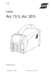
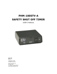
MED TEST
USER’S MANUAL
SOF-MED-TEST User’s Manual
DOC-200
Rev. 1.0
Copyright © 2008
All Rights Reserved
MED Associates, Inc.
P.O. Box 319
St. Albans, Vermont 05478
www.med-associates.com
MED ASSOCIATES INC.
MED TEST
- ii -
MED ASSOCIATES INC.
MED TEST
TABLE OF CONTENTS
Introduction.......................................................................................... 1
Main Menu ..................................................................................................... 1
Standard Cards Menu ............................................................................ 5
Standard Input Card Test ................................................................................. 5
Standard Output Card Test ............................................................................... 6
SuperPort™ Menu .................................................................................. 7
SuperPort Input Card Test ................................................................................ 7
SuperPort DIG-726 and DIG-727 Output Card Test............................................... 8
SmartCtrl™ Menu .................................................................................. 9
SmartCtrl Card Tests ....................................................................................... 9
Testing SmartCtrl Inputs .................................................................................. 9
Testing SmartCtrl Outputs .............................................................................. 10
Pumps Menu........................................................................................ 11
PHM-100VSS Test ......................................................................................... 11
PHM-104 Test ............................................................................................... 11
PHM-104A Test ............................................................................................. 12
PHM-106 Test ............................................................................................... 12
PHM-111 Test ............................................................................................... 13
Misc Modules Menu ............................................................................. 14
Interface Card .............................................................................................. 14
MED Driver Cleaner ....................................................................................... 15
ANL-926 Test ............................................................................................... 15
ENV-413 Test ............................................................................................... 16
ENV-520 Test ............................................................................................... 17
PHM-15X Test............................................................................................... 17
Appendix A .......................................................................................... 19
Transition / Level Modes ................................................................................ 19
Normal / Invert............................................................................................. 19
- iii -
MED ASSOCIATES INC.
MED TEST
INTRODUCTION
The Med Test Hardware Test Utility is a software application that is supplied with MEDPC IV and other software applications from MED Associates. Med Test features menu
selectable routines for independently testing the MED timer, the interrupt system, and
individual modules. This is particularly useful when initially setting up a system, as well
as in trouble shooting any issues that are not easily discernible as hardware or software
related. To invoke this program, simply open Med Test from the desktop icon or select
Start | Programs sequence used for all Windows applications.
WARNING!!
Do not remove any cards from the computer or interface cabinet without first turning the
power off to both the computer and the interface cabinet. Failure to do so could result in
damage to the MED Associates DIG-704 card, the computer or both.
WARNING!!
MED Test should not be run while any other MED Associates software is being run.
Doing so will cause problems with the DIG-704 and it’s driver. MED Test will interfere
with other MED Associates software and should not be run at the same time.
Main Menu
From the main menu, select Exit, Standard Cards, SuperPort™, SmartCtrl™, Pumps, Misc
Modules, Window or Help.
Figure 1 - The MED Test Main Menu Screen
- 1 -
MED ASSOCIATES INC.
MED TEST
Exit
The Exit menu is used to exit the Med Test Utility.
Standard Cards
The Standard Cards menu (Figure 2) is used to test any MED Associates standard Input
or Output cards.
Figure 2 - Standard Cards Menu
SuperPort™
The SuperPort menu (Figure 3) is used to test the DIG-712/713 Input cards as well as
the DIG 726 and DIG-727 Output cards.
Figure 3 - SuperPort Menu
SmartCtrl™
The SmartCtrl menu (Figure 4) is used the test the DIG-715 or DIG-716 Smart Control
cards and the DIG-703 USB Interfaces.
Figure 4 - SmartCtrl Menu
- 2 -
MED ASSOCIATES INC.
MED TEST
Pumps
The Pumps menu (Figure 5) is used to test the PHM-100VSS, PHM-104, PHM-104A, PHM106 and PHM-111 syringe pumps.
Figure 5 - Pumps Menu
Misc Modules
The Misc Modules menu (Figure 6) is used to test the DIG-704C Interface card timing and
interrupt functions as well as the ANL-926 Programmable Audio Generator functions. It
may also be used to test the ENV-413 Constant Current Aversive Stimulator, ENV-520 48Channel I.R. Controller and the PHM-15X ICSS Stimulators. (This includes the PHM-150B,
PHM-150B/2, PHM-152 and PHM-152/2). The MED Driver Cleaner program can also be
run from this menu.
These tests are also described in detail later in this manual. On screen help is not
available at this time, so please refer to the information in this chapter if there are any
questions. For the most part, each test function is straightforward and intuitive.
Figure 6 - Misc Modules Menu
- 3 -
MED ASSOCIATES INC.
MED TEST
Window
The Window menu options (Figure 7) allow the user to organize multiple test screens for
easier viewing.
Figure 7 - Window Menu
Help
The Help Menu (Figure 8) displays the software version and copyright information for the
MED Test software. Click OK to close this window.
Figure 8 - Help Information
- 4 -
MED ASSOCIATES INC.
MED TEST
STANDARD CARDS MENU
Standard Input Card Test
The standard input card test (Figure 9) must be set to the port address of the card to be
tested. The first standard card in any system is factory set to Port 780. When first
opening this test, press Alt+C or click the Clear Card button. Check that the interface
card is set to the port address that has been entered. Once the card is cleared, it is now
possible to test each individual input. If, for example, the Left Lever in box 1 is
connected to Input 1 and the Right Lever to Input 2, then alternately pressing the left
and right levers causes the red indicator lights to change from 1 to 2 while the Repeat
Count remains at 1. Pressing the same lever repeatedly causes the Repeat Count to
increment.
Figure 9 - Standard Input Card Test Screen
- 5 -
MED ASSOCIATES INC.
MED TEST
Standard Output Card Test
The standard output card test (Figure 10), like the standard input card test, must be set
to the port address of the card being tested. The current factory default for the first
card is Port 780, with each additional card assigned the next incremental value, 781,
782, 783, etc. On some older interfaces, the first output card is set to Port 784. This
selection can also be used to test the DIG-724, a special output card designed to drive
24 low current loads such as small stimulus lights, small house lights, and projection
displays on pigeon pecking keys. Three sequential port numbers must be entered for
each DIG-724 card; otherwise the test is identical to the standard output card.
Figure 10 - Standard Output Card Test Screen
Individual outputs may be activated in a number of different ways. Each time an output
is turned on, the corresponding indicator on the screen turns red. Similarly, the LED on
the output module (if present) should also turn on, as well as the device connected to
the output bit that has been activated. Outputs may be turned on by typing Alt+T or
with the Toggle Bits button -- each time this button is clicked the output bits are
sequenced from 1 to 2 to 3 ... to 8. Following bit 8, all bits are activated simultaneously
and finally all bits are turned off. Individual outputs may also be turned on using the
individual buttons associated with each output. Click once to turn the output on and
again to turn it off. Finally, type Alt+A or click Auto Test to automatically toggle through
the output bits. If the output card fails any test, check to make sure the interface is
properly installed in the computer and connected via the ribbon cable to the decoder card
in the interface cabinet and that the interface cabinet and 28 VDC supplies are turned on.
Finally, check that the interface card is set to the port value entered and that the
controlled device is functioning independent of the interface and is properly connected to
the app.
- 6 -
MED ASSOCIATES INC.
MED TEST
SUPERPORT™ MENU
SuperPort Input Card Test
This test is virtually the same as for the standard Input Module. The only difference is
that two address values must be entered, the port address and the offset value or
address. The factory standard for the first SuperPort Input card is 789 for the port
address and 0 for the offset value. The second SuperPort Input card will be set at 789
and 2, the third at 789 and 4, the fourth at 789 and 6, and so on. These are of course
arbitrary values, which can be changed on the board; however, multiple modules must be
set sequentially with no gaps in the offset numbers. See the MED-PC User’s Manual for
details.
See additional information in Appendix A for proper interpretation of
transition/level and normal/inverted settings on input cards.
Figure 11 - SuperPort Input Card Test Screen
- 7 -
MED ASSOCIATES INC.
MED TEST
SuperPort DIG-726 and DIG-727 Output Card Test
These tests, like the SuperPort Input test, require a port address and the offset value or
address. The factory standard for the first SuperPort Output card is 792 for the port
address and 0 for the offset value. The second SuperPort Output card will be set at 792
and 2, the third at 792 and 4, the fourth at 792 and 6, and so on.
Like the test for the standard output DIG-721 module, both tests offer the ability to enter
a unique output value (binary equivalent of all outputs to be turned on), individual
buttons for each output, a toggle button for each set of 8 outputs, and an automatic test
sequence to verify all 16 or 32 outputs depending upon the card being tested.
Figure 12 - SuperPort Output Card Test Screen
- 8 -
MED ASSOCIATES INC.
MED TEST
SMARTCTRL™ MENU
SmartCtrl Card Tests
All SmartCtrl modules are unique in that the inputs and outputs are on the same card;
therefore, only one test screen is provided for each card.
Testing SmartCtrl Inputs
Functionally, the SmartCtrl inputs operate in the same manner as a standard input card.
The first card is set to port 780, the second to port 781, the third to 782 and so on. To
test the input function, type Alt+C or click the Clear Inputs button to change the input
value to 0. See the Standard Input Card Test for additional information. Each input to
the card should light the respective input bit, update the input value, and increment the
repeat count according to the transition/level and normal/invert settings on the card.
See Appendix A for more information regarding transition/level and normal/invert
settings.
Figure 13 - DIG-716 SmartCtrl Test Screen
- 9 -
MED ASSOCIATES INC.
MED TEST
Testing SmartCtrl Outputs
Functionally, the SmartCtrl outputs operate in the same manner as a SuperPort. All cards
are set to port 792-793. This setting cannot be changed. The out offset value of the
first card is set to 0; the second card is set to 2, the third to 4, and so on. This is also
true for the DIG-716 card, even though this card has only 8 outputs and the odd
numbered offsets are never used. Just like the SuperPort Output Card Test, each test
box provides the ability to enter a unique output value and send it to the card being
tested. Clicking individual output buttons activates the respective output. Typing Alt+T
or clicking the Toggle Bits button sequences the outputs one at a time, followed by all
outputs being turned on, and finishing with all outputs being turned off. The Auto Test
button automatically performs the toggle sequence of all 8 or 16 outputs, depending on
the card being tested.
Figure 14 - DIG-716B SmartCtrl Test Screen
- 10 -
MED ASSOCIATES INC.
MED TEST
PUMPS MENU
PHM-100VSS Test
To run the PHM-100VSS Test click Pumps | PHM-100VSS. Enter the Node number of
the pump to be tested. Then enter the desired RPMs and Infusion Time in seconds.
Click Set Pump to begin. A number should appear in the "Sum Check Sent" box. If
communication was successful, the "Sum Check Rec" box should contain the same
number. If the "Sum Check Rec" box contains a different number, check the hardware
connections and node settings.
Figure 15 - PHM-100VSS Test Screen
PHM-104 Test
To run the PHM-104 Test click Pumps | PHM-104. Enter the Node number of the
pump to be tested. Set the desired Dose (ul), Rate (ul/sec) and Syringe Size (ul). Click
Set Pump to begin. A number should appear in the "Sum Check Sent" box. If
communication was successful, the "Sum Check Rec" box should contain the same
number. If the "Sum Check Rec" box contains a different number, check the hardware
connections and node settings.
Figure 16 - PHM-104 Test Screen
- 11 -
MED ASSOCIATES INC.
MED TEST
PHM-104A Test
To run the PHM-104A Test click Pumps | PHM-104A. Select the pump to be tested
from the Pump ID pulldown menu. Set the Syringe Size (ul), Dose (ul) and Rate (ul/sec).
Next select the desired command from the Send Command pulldown menu. Click Reset
to reset the injected volume that is displayed in the Injected window.
The status of the pump is indicated in the Command Status area of the screen. If the
Command Status is Invalid Pump, verify that it is properly connected and turned on, then
click Reset and try again. If the Command Status is Invalid Data, the Dose and/or Rate
is not within the acceptable range. Refer to the PHM-104A User’s Manual for more
detailed information.
Figure 17 - PHM-104A Test Screen
PHM-106 Test
To run the PHM-106 Test click Pumps | PHM-106. Enter the Node number of the
pump to be tested, the desired Rate and the Syringe Diameter (mm). Next select
microliters or milliliters from the Volume pulldown menu and seconds or minutes from the
Time pulldown menu. Click Set Flow Rate to begin. A number should appear in the
"Sum Check Sent" box. If communication was successful, the "Sum Check Rec" box
should contain the same number. If the "Sum Check Rec" box contains a different
number, check the hardware connections and node settings.
Figure 18 - PHM-106 Test Screen
- 12 -
MED ASSOCIATES INC.
MED TEST
PHM-111 Test
To run the PHM-111 Test click Pumps | PHM-111. Select the pump to be tested from
the Pump ID pulldown menu. Enter the cross sectional area of the syringe into the
Syringe (sqcm) field. The information that must be entered into the Start (cc/hr), End
(cc/hr), Dose (cc) and Time (min) depends on the command selected from the Send
Command pulldown menu. Refer to the PHM-111 User’s Manual for more detailed
information regarding these commands.
Figure 19 - PHM-111 Test Screen
- 13 -
MED ASSOCIATES INC.
MED TEST
MISC MODULES MENU
Interface Card
Timer Test
To run the Timer Test select Misc Modules | Interface Card from the Med Test dialog
box (Figure 6). Click the appropriate button (Figure 20) followed by typing Alt+S or
clicking the Start Test button. The test runs for approximately 5-10 seconds and a
Timer Test Passed message should appear. If the test fails, try reseating the card in
the computer and remove any card that may be in conflict with ports 768-796,
Hexadecimal 300-31C. Exit by clicking the Exit button.
Figure 20 - Interface Card Timer and Interrupts Test Screen
Interrupt Test
Select the Interrupt Test option to test the interface card interrupt. Interrupt Test
Passed! message should appear approximately 5-10 seconds after starting the test. If it
does not, contact MED Associates Technical Support.
Time Base Test
The Time Base Test is intended to verify that the Time Base of the PCI card is set to 500
μs.
- 14 -
MED ASSOCIATES INC.
MED TEST
MED Driver Cleaner
Selecting the MED Driver Cleaner option from the Misc Modules menu will cause the
prompt shown in Figure 21 to appear. DO NOT CLICK YES UNLESS INSTRUCTED TO
DO SO BY A MED ASSOCIATES TECHNICAL SUPPORT SPECIALIST. Clicking Yes
will cause all MED Associates device drivers to be deleted and removed from the
computer.
Figure 21 - MED Driver Cleaner Prompt
ANL-926 Test
Select the Misc Modules | ANL-926 menu item (Figure 6) to produce the ANL-926
dialog box (Figure 22). Select the stimulus type (Pure Tone, White Noise or Click) using
the tab and up/down arrow keys or click the associated button.
Figure 22 - ANL-926 Test Screen
Port Address: Select the Port Address from the pulldown menu.
Stimulus: Select Pure Tone, White Noise or Click
Node Number: Nodes are set with dipswitches on the module labeled OFFSET ADDRESS
A1 - A8. The switch uses inverted logic; i.e., with all switches ON the setting is 0 (zero).
Each switch has a binary value starting with A1 = 1, A2 = 2, A3 = 4, ... A8 = 128. The
node is generally set to the box value. For example the ANL-926 for box #3 would have
- 15 -
MED ASSOCIATES INC.
MED TEST
switches A1 & A2 in the off position. Note: The ANL-926 uses port values 790-791. Be
sure that no other card is set to these addresses.
Frequency: The frequency setting is disabled for white noise and limited to 10 Hz for
click. The rise/fall range of pure tone signals may be limited by the efficiency of the
speaker. Enter the desired value using the scroll arrows or by typing the desired value.
Amplitude: See the instruction sheet for calibrating the speaker to the ANL-926.
Calibration should be at or near the desired frequency. The selected values will be
presented electronically to the speaker. Actual sound levels may vary based on the
efficiency of the speaker.
Rise/Fall Time: A single setting determines the rise and fall time for the designated
stimulus. In other words, the time required to “ramp up” to the set amplitude and the
time required to “ramp down” to zero amplitude are equal. Longer settings produce
slower ramps that lessen speaker pop. Note, this time is added to duration. Rise/fall is
disabled for the click stimulus.
Duration: Set the desired duration, if required. Duration is the interval during which
the signal is at full amplitude. This may or may not start at time 0, depending on the
rise/fall setting.
ENV-413 Test
Select the Misc Modules | ENV-413 menu item (Figure 6) to produce the ENV-413 test
screen (Figure 23). Select the node number from the Node pulldown menu. (Refer to
the ENV-413 User’s Manual for detailed information regarding node numbers). Enter the
desired Current (mA) and Duration (ms). Click Shock to send these values to the ENV413. Click Shock On to turn on the aversive stimulus at the set current level and click
Shock Off to turn off the aversive stimulus.
Figure 23 - ENV-413 Test Screen
- 16 -
MED ASSOCIATES INC.
MED TEST
ENV-520 Test
Select the Misc Modules | ENV-520 menu item (Figure 6) to produce the ENV-520 test
screen (Figure 24). Select the node number from the Node pulldown menu. (Refer to
the ENV-520 User’s Manual for detailed information regarding node numbers). Enter the
desired Resolution. Enable 32 Beam if a 32-beam system is being tested. Click Start
IRQ to begin the test. When a beam is broken the corresponding indicator on the test
screen will turn red.
Figure 24 - ENV-520 Test Screen
PHM-15X Test
Select the Misc Modules | PHM-15X menu item (Figure 6) to produce the PHM-15X
test screen (Figure 25). Select the mode from the Mode menu (PHM-150, PHM-152,
PHM-152I or PHM-152V). Nine Waveform Parameters governing the stimulus train are
displayed with default values on the left side of the screen. (For more information
regarding Waveform Parameters refer to the PHM-15X User’s Manual).
Each parameter may be changed within the range specified in Table 1. However, they
are not mutually exclusive (i.e. Pulse and Delay values must be compatible with Duration
and Frequency values.) Error messages will appear when incompatible values are
selected.
Once the desired parameters have been selected, they must be sent to the Stimulator
hardware. Click on the Stimulate button to do this. A number should appear in the
"Sum Check Sent" box. If communication was successful, the "Sum Check Rec" box
should contain the same number. If the "Sum Check Rec" box contains a different
number, check the hardware connections and node settings.
- 17 -
MED ASSOCIATES INC.
MED TEST
Figure 25 - PHM-15X Test Screen
Table 1 - Operating Parameters
Description
SW Default Value
Allowable Range
Pulse 1
500 us
60 – 32,000 us
Delay 1
500 us
60 – 32,000 us
Pulse 2
500 us
60 – 32,000 us
Delay 2
(* 1 )
60 – 500,000 us
Duration
5000 ms
(* 2 )
Frequency
100 Hz
1 – 2000 Hz (* 3 )
Amplitude 1
200 uA
0 – 1000 uA
Amplitude 2
200 uA
0 – 1000 uA
Stim Node
1
1 – 16 (* 4 )
Stim Port
1
1 – 2 (* 4 )
(* 1 ) Not directly adjustable.
Automatically set by the formula (1,000,000 / Frequency) – (Pulse 1 + Delay 1 + Pulse 2).
(* 2 ) Must permit a minimum of one cycle.
(* 3 ) Limited by the Pulse and Delay parameters.
(* 4 ) Must correspond with module setting.
NOTE: Period is the total time for one cycle or the sum (Pulse 1 + Delay 1 + Pulse 2 +
Delay 2).
- 18 -
MED ASSOCIATES INC.
MED TEST
APPENDIX A
Transition / Level Modes
The above example assumes that the input card is in the normal and transition modes.
Note: If using a level input (see transition/level settings in the modules manual), holding
the lever or blocking a photo-beam results in the repeat count incrementing
approximately 10 counts per second until the input is released.
Normal / Invert
The invert setting causes an input to be activated when the input is opened or released.
For example, with transition, the repeat count increments when the lever is released
instead of when it is pressed (assuming that the lever is wired to the NO, Normally Open,
contact). With a level-inverted combination, the repeat count may run continuously,
stopping only when a lever is held or photo-beam broken. In general, use the factory
default settings of normal/transition for most response devices (levers, nose poke, head
entry detectors, etc.). Use a normal/level if it is desired to time a photo-beam break or
use software control to slow down rapid fringe responses, and use inverted/transition
with MED Associates, Ralph Gerbrands, and other pigeon pecking keys featuring a NC
(normally closed) contact.
To return to the main menu screen type Alt+X or click the Exit button.
- 19 -